EP3557295A1 - Pièce de connexion optique - Google Patents
Pièce de connexion optique Download PDFInfo
- Publication number
- EP3557295A1 EP3557295A1 EP17881851.4A EP17881851A EP3557295A1 EP 3557295 A1 EP3557295 A1 EP 3557295A1 EP 17881851 A EP17881851 A EP 17881851A EP 3557295 A1 EP3557295 A1 EP 3557295A1
- Authority
- EP
- European Patent Office
- Prior art keywords
- optical
- fiber
- bent portion
- region
- optical fiber
- Prior art date
- Legal status (The legal status is an assumption and is not a legal conclusion. Google has not performed a legal analysis and makes no representation as to the accuracy of the status listed.)
- Pending
Links
Images


Classifications
-
- G—PHYSICS
- G02—OPTICS
- G02B—OPTICAL ELEMENTS, SYSTEMS OR APPARATUS
- G02B6/00—Light guides; Structural details of arrangements comprising light guides and other optical elements, e.g. couplings
- G02B6/24—Coupling light guides
- G02B6/42—Coupling light guides with opto-electronic elements
- G02B6/4292—Coupling light guides with opto-electronic elements the light guide being disconnectable from the opto-electronic element, e.g. mutually self aligning arrangements
-
- G—PHYSICS
- G02—OPTICS
- G02B—OPTICAL ELEMENTS, SYSTEMS OR APPARATUS
- G02B6/00—Light guides; Structural details of arrangements comprising light guides and other optical elements, e.g. couplings
- G02B6/24—Coupling light guides
- G02B6/42—Coupling light guides with opto-electronic elements
- G02B6/4201—Packages, e.g. shape, construction, internal or external details
- G02B6/4202—Packages, e.g. shape, construction, internal or external details for coupling an active element with fibres without intermediate optical elements, e.g. fibres with plane ends, fibres with shaped ends, bundles
-
- G—PHYSICS
- G02—OPTICS
- G02B—OPTICAL ELEMENTS, SYSTEMS OR APPARATUS
- G02B6/00—Light guides; Structural details of arrangements comprising light guides and other optical elements, e.g. couplings
- G02B6/24—Coupling light guides
- G02B6/245—Removing protective coverings of light guides before coupling
-
- G—PHYSICS
- G02—OPTICS
- G02B—OPTICAL ELEMENTS, SYSTEMS OR APPARATUS
- G02B6/00—Light guides; Structural details of arrangements comprising light guides and other optical elements, e.g. couplings
- G02B6/24—Coupling light guides
- G02B6/36—Mechanical coupling means
-
- G—PHYSICS
- G02—OPTICS
- G02B—OPTICAL ELEMENTS, SYSTEMS OR APPARATUS
- G02B6/00—Light guides; Structural details of arrangements comprising light guides and other optical elements, e.g. couplings
- G02B6/24—Coupling light guides
- G02B6/42—Coupling light guides with opto-electronic elements
- G02B6/4201—Packages, e.g. shape, construction, internal or external details
- G02B6/4204—Packages, e.g. shape, construction, internal or external details the coupling comprising intermediate optical elements, e.g. lenses, holograms
- G02B6/421—Packages, e.g. shape, construction, internal or external details the coupling comprising intermediate optical elements, e.g. lenses, holograms the intermediate optical component consisting of a short length of fibre, e.g. fibre stub
-
- G—PHYSICS
- G02—OPTICS
- G02B—OPTICAL ELEMENTS, SYSTEMS OR APPARATUS
- G02B6/00—Light guides; Structural details of arrangements comprising light guides and other optical elements, e.g. couplings
- G02B6/24—Coupling light guides
- G02B6/36—Mechanical coupling means
- G02B6/3628—Mechanical coupling means for mounting fibres to supporting carriers
- G02B6/3632—Mechanical coupling means for mounting fibres to supporting carriers characterised by the cross-sectional shape of the mechanical coupling means
- G02B6/3636—Mechanical coupling means for mounting fibres to supporting carriers characterised by the cross-sectional shape of the mechanical coupling means the mechanical coupling means being grooves
-
- G—PHYSICS
- G02—OPTICS
- G02B—OPTICAL ELEMENTS, SYSTEMS OR APPARATUS
- G02B6/00—Light guides; Structural details of arrangements comprising light guides and other optical elements, e.g. couplings
- G02B6/24—Coupling light guides
- G02B6/36—Mechanical coupling means
- G02B6/3628—Mechanical coupling means for mounting fibres to supporting carriers
- G02B6/3648—Supporting carriers of a microbench type, i.e. with micromachined additional mechanical structures
- G02B6/3652—Supporting carriers of a microbench type, i.e. with micromachined additional mechanical structures the additional structures being prepositioning mounting areas, allowing only movement in one dimension, e.g. grooves, trenches or vias in the microbench surface, i.e. self aligning supporting carriers
-
- G—PHYSICS
- G02—OPTICS
- G02B—OPTICAL ELEMENTS, SYSTEMS OR APPARATUS
- G02B6/00—Light guides; Structural details of arrangements comprising light guides and other optical elements, e.g. couplings
- G02B6/24—Coupling light guides
- G02B6/42—Coupling light guides with opto-electronic elements
- G02B6/4201—Packages, e.g. shape, construction, internal or external details
- G02B6/4204—Packages, e.g. shape, construction, internal or external details the coupling comprising intermediate optical elements, e.g. lenses, holograms
- G02B6/4214—Packages, e.g. shape, construction, internal or external details the coupling comprising intermediate optical elements, e.g. lenses, holograms the intermediate optical element having redirecting reflective means, e.g. mirrors, prisms for deflecting the radiation from horizontal to down- or upward direction toward a device
-
- G—PHYSICS
- G02—OPTICS
- G02B—OPTICAL ELEMENTS, SYSTEMS OR APPARATUS
- G02B6/00—Light guides; Structural details of arrangements comprising light guides and other optical elements, e.g. couplings
- G02B6/24—Coupling light guides
- G02B6/42—Coupling light guides with opto-electronic elements
- G02B6/4201—Packages, e.g. shape, construction, internal or external details
- G02B6/4219—Mechanical fixtures for holding or positioning the elements relative to each other in the couplings; Alignment methods for the elements, e.g. measuring or observing methods especially used therefor
- G02B6/4236—Fixing or mounting methods of the aligned elements
- G02B6/424—Mounting of the optical light guide
- G02B6/4243—Mounting of the optical light guide into a groove
Definitions
- the present invention relates to an optical connection component.
- Patent Literature 1 Japanese Unexamined Patent Publication No. 2011-7946
- optical fibers used in the foregoing optical connection component have a significant fiber length tolerance during manufacturing. Accordingly, a long fiber length is retained for an optical fiber when an optical connection component is manufactured, such that an optical fiber is not affected by a tolerance. Therefore, when an optical connection component is attached to the exterior of an optical module, both ends of an optical fiber are fixed in a state of being deflected in a longitudinal direction. In this case, since a state in which stress is applied to a bent portion of the optical fiber in the optical connection component continues, there is a possibility that damage to the optical connection component may be accelerated.
- the present invention has been made in consideration of the foregoing circumstances, and an object thereof is to provide an optical connection component in which stress applied to the optical fiber can be reduced.
- an optical connection component including an optical fiber in which a bent portion is formed, and a fiber fixing part configured to fix the optical fiber to an optical module.
- the optical fiber includes a glass fiber and a resin coating which covers the glass fiber. The resin coating is removed and the glass fiber is exposed at one end of the optical fiber.
- the fiber fixing part includes an optical array member which supports an end portion of the exposed glass fiber and a protective resin which coats the optical fiber. A distal end of the glass fiber and an end surface of the optical array member form a reference surface configured to be fixed to the optical module.
- the bent portion is formed in a region including the exposed glass fiber and is covered with the protective resin. A predetermined section in a region, which continues from the bent portion on a side opposite to an end portion of the optical fiber supported by the fiber fixing part with the bent portion interposed therebetween, is inclined to approach the reference surface while going away from the bent portion.
- an optical connection component in which stress applied to the optical fiber can be reduced is provided.
- FIG. 1 is a view for describing an optical connection component according to an embodiment of the present invention and an application state thereof.
- FIG. 2 is an enlarged view of a portion in the vicinity of a fiber fixing part 20 in an optical connection component 1.
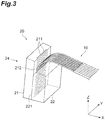
- FIG. 3 is a perspective view of a portion in the vicinity of the fiber fixing part 20.
- a protective resin included in the fiber fixing part 20 is not illustrated.
- FIGS. 1 to 3 , and FIG. 4 which will be described below, the positional relationship between the optical connection component and an electronic substrate is described in an orthogonal coordinate system (XYZ coordinate system).
- FIG. 1 illustrates a state in which the optical connection component 1 is connected to an electronic substrate 100 including an optical integrated circuit chip and the like.
- the optical connection component 1 includes an optical fiber 10 of which one end portion has a bent portion BA (bent optical fiber) subjected to heating and bending treatment, the fiber fixing part 20 which is attached to the end portion where the bent portion BA of the optical fiber 10 is formed, and a connector 30 which is attached to the other end portion opposite to the bent portion BA side of the optical fiber 10.
- the electronic substrate 100 functions as a part of an optical module described in the present embodiment.
- the optical connection component 1 is a part attached to this optical module.
- the optical fiber 10 has a glass fiber 11 (bare fiber) and a resin coating 12 which surrounds the glass fiber 11. Since the bent portion BA is formed in the optical fiber 10, a multi-mode optical fiber (MMF) is generally utilized. However, the optical fiber 10 is not limited thereto, and a single-mode optical fiber (SMF) or the like may be used.
- the fiber diameter of the optical fiber 10 can be 125 ⁇ m.
- the fiber length of the optical fiber 10 can be within a range of approximately several centimeters to several tens of centimeters.
- the resin coating 12 of the optical fiber 10 is removed in the end portion on one side where the bent portion BA is formed.
- the fiber fixing part 20 has a function of fixing the end portion on one side of the optical fiber 10 including the bent portion BA.
- the optical fiber 10 is fixed by the fiber fixing part 20 and is connected to the electronic substrate 100 in a state in which its shape is maintained.
- a plurality (eight in FIG. 3 ) of optical fibers 10 are arranged in parallel in one direction (Y-axis direction) while forming a so-called tape-like multi-core optical fiber.
- the number of optical fibers 10 arranged in parallel is not particularly limited, and only one optical fiber may be adopted.
- the connector 30 is connected to the end portions on the other side of the optical fibers 10.
- the connector 30 has a function of optically connecting the optical fibers 10 and another optical fiber for premises wiring or a single-mode optical fiber (SMF) such as an external transmission line to each other.
- SMF single-mode optical fiber
- the optical fiber 10 includes a region A (first non-bent section which continues to bent portion BA) having a curvature d of 0.1 [1/mm] or smaller, a region B (section corresponding to the bent portion BA subjected to heating and bending treatment) having a predetermined curvature d of 0.4 [1/mm] or larger, and a region C (second non-bent section which continues to the bent portion BA) having a curvature d of 0.1 [1/mm] or smaller.
- a boundary R1 indicates the boundary between the region A and the region B
- a boundary R2 indicates the boundary between the region B and the region C.
- the section (bent portion BA) subjected to heating and bending treatment is formed to have a bent shape through heating and bending treatment.
- the region A and the region B are formed in a portion in which the resin coating 12 is removed such that a surface of the glass fiber 11 (glass portion) is exposed.
- the optical fiber 10 extends substantially in a Z-axis direction in the region A, is bent by substantially 90° in the region B, and extends substantially in an X-axis direction in the region C. However, details of a bending angle and the like of the optical fiber 10 will be described below.
- a method for heating and bending treatment of the regions B corresponding to the bent portions BA of the optical fibers 10 is not particularly limited.
- a burner, a CO 2 laser, arc discharge, or a heater can be utilized.
- a CO 2 laser can easily have an irradiation intensity, an irradiation range, and an irradiation time thereof adjusted, thereby having characteristics advantageous to minute controlling of a curvature distribution. It is conceivable that since glass becomes opaque near a wavelength of 10 [ ⁇ m] which is a general wavelength of a CO 2 laser, the irradiation energy of a CO 2 laser is absorbed by a surface layer of an optical fiber and is transferred due to re-radiation and heat conduction.
- the irradiation power of a CO 2 laser is appropriately adjusted such that distortion is eliminated in a fiber cross section of a heated portion by causing a state, in which the surface layer glass of an optical fiber does not evaporate and the temperature has risen to the point of operation or higher, to continue for a predetermined time.
- the fiber fixing part 20 has a V-groove substrate 21 and a lid 22 which support the regions A of the optical fibers 10, and a protective resin 23 which reinforces and protects the bent portions BA of the optical fibers 10.
- the V-groove substrate 21 includes a holding surface 212 on which V-grooves 211 for arraying the regions A of the optical fibers 10 are formed.
- the lid 22 restricts the positions of the regions A of the arrayed optical fibers 10 together with the V-grooves 211 using a holding surface 221.
- the V-groove substrate 21 and the lid 22 function as an optical array member 24 for arraying the optical fibers 10 by supporting the end portions of the optical fibers 10 in the fiber fixing part 20.
- a holding portion for holding the optical fibers 10 is formed by the V-grooves 211 formed on the holding surface 212 of the V-groove substrate 21, and the holding surface 221 of the lid 22 facing the holding surface 212.
- An end surface of the holding portion (end surface of the electronic substrate 100) is flat in a state in which the optical fibers 10 are exposed to the end surface, thereby forming a light input-output end surface for the optical fibers 10.
- the light input-output end surface for the optical fibers 10, and the optical integrated circuit chip and the like of the electronic substrate 100 are optically connected to each other with the fiber fixing part 20 interposed therebetween. According to such a structure, improvement of mechanical strength in a connection portion between the optical fibers 10 and the electronic substrate 100 can be achieved.
- V-groove substrate 21 and the lid 22 multi-component glass such as Pyrex (registered trademark), a SiO 2 substrate, or the like can be used, but they are not limited thereto.
- a UV-curable resin when an end surface of the fiber fixing part 20 is connected to the electronic substrate 100, there are cases in which bonding is performed using a UV-curable resin. In this case, if a material, through which UV light is transmitted, is used in at least a portion of the V-groove substrate 21 and the lid 22, bonding and fixing using a UV-curable resin can be appropriately performed.
- the length of the V-groove substrate 21 in the longitudinal direction (Z-axis direction in FIGS. 1 to 3 ) of the holding portion is set to be longer than the length of the lid 22 in the same Z-axis direction.
- the regions A of the optical fibers 10 are supported by the V-groove substrate 21 and the lid 22, and the bent portion BA (region B) is disposed away from the lid 22.
- the protective resin 23 is provided to reinforce this bent portion BA (region B) and the region C which continues from the bent portion BA.
- the protective resin 23 is provided to cover the region in which the resin coating 12 is removed and the glass fiber 11 is exposed in the optical fibers 10.
- a material of the protective resin 23 is not particularly limited, and a UV-curable resin or the like can be used.
- the optical array member 24 of the fiber fixing part 20 is not limited to the structure described in the present embodiment.
- the optical array member 24 for fixing the regions A in the end portions of the optical fibers 10 is constituted of the V-groove substrate 21 and the lid 22.
- the optical array member 24 may be constituted of a single member.
- the shape for holding the regions A of the optical fibers 10 is not limited to those of the V-grooves 211.
- a structure of holding a plurality of optical fibers 10 using a member, in which penetration holes corresponding to the number of optical fibers 10 are provided such that the regions A of the optical fibers 10 are respectively inserted into the penetration holes may be adopted.
- a ferrule having a structure similar to that of a single-core optical connector such as an FC, an SC, and an LC, or a multi-core connector such as an MPO and an MT can be applied to a portion of the fiber fixing part 20 in which the holding portion is formed.
- optical connection component 1 When the foregoing optical connection component 1 is attached to the exterior of the optical module, the fiber fixing part 20 and the connector 30 are in a fixed state.
- the optical connection component 1 is attached to an upper portion of the electronic substrate 100 in this state and is used in a manner of being integrated with the optical module.
- the shape of the optical fiber 10 in the optical connection component 1 according to the present embodiment will be described.
- the bent portion BA is formed in the optical fiber 10 through heating and bending treatment.
- the bending angle is set in consideration of the extending direction of the fiber when the optical connection component 1 is attached to the electronic substrate 100.
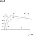
- FIG. 4 is a view for describing an angle of each portion of the optical fiber 10.
- the optical fiber 10 is indicated with a dotted line, and extending directions L1 and L2 of the optical axes in the region A and the region C in the optical fiber 10 are indicated with solid lines.
- a reference surface S is a surface extending along the XY-plane and is indicated with a solid line extending in the X-axis direction in FIG. 4 .
- the reference surface S is a surface corresponding to a main surface of the electronic substrate 100 to which the optical connection component 1 is connected. That is, the reference surface S is the end surface of the fiber fixing part 20 of the optical connection component 1 and corresponds to the light input-output end surface of the optical fiber 10.
- the region C which continues from the bent portion BA (region B) is inclined to approach the reference surface while going away from the bent portion BA.
- an inclination angle of the region C in the optical fiber 10 of the optical connection component 1 in the downward direction (negative Z-direction) with respect to the extending direction (XY-plane) of the reference surface S is ⁇ , 0° ⁇ is satisfied.
- an inclination angle of the region A in the end portion of the optical fiber 10 of the optical connection component 1 with respect to a direction perpendicular to the reference surface S is referred to as ⁇ .
- the bending angle of the bent portion BA that is, an angle formed by two straight lines respectively extending along the region A and the region C is referred to as ⁇ .
- the inclination angle ⁇ of the region A in the optical fiber 10 can have a relationship of 0° ⁇ 15°.
- the sum of ⁇ and ⁇ may be 90° or wider, that is, the bending angle ⁇ may have a relationship of 90° ⁇ + ⁇ .
- the region C which continues from the bent portion BA (region B) of the optical fiber 10 is inclined to approach the reference surface, it is possible to alleviate the stress applied to the optical fiber 10 after being assembled as the optical module.
- stress applied to the bent portion BA can be favorably alleviated.
- the region C of an optical fiber continuously extending in the X-axis direction from the bent portion BA is designed such that it becomes parallel to the reference surface S (the main surface of the electronic substrate 100 which is an attachment target for the optical connection component).
- a fiber length tolerance occurs in the optical fibers during manufacturing, and it is general that this fiber length tolerance is larger than the dimensional tolerance of an optical module to which the optical connection component including the optical fibers is attached. Therefore, it has been general to employ a technique of preparing for a situation in which the fiber length becomes insufficient due to the tolerance, by manufacturing optical fibers such that the central value of the lengths of the optical fibers becomes slightly larger than the dimensions of the optical module.
- an optical connection component is manufactured using optical fibers which are manufactured such that the central value of the fiber lengths becomes larger than the dimensions of the optical module
- the optical fibers may be deflected when being fixed to the exterior of the optical module. That is, if a fiber fixing part and a connector are disposed in accordance with the exterior of the optical module, most of the optical fibers are longer than the dimensions of the optical module due to the central value of the fiber lengths being longer than the dimensions of the optical module. Therefore, there are cases in which portions corresponding to the regions C of the optical fibers may be pushed from both ends and a deflection may occur. Stress derived from a force for tending to return to the original state is applied to the deflected optical fibers.
- the region C which continues from the bent portion BA (region B) is inclined to approach the reference surface while going away from the bent portion BA. It is conceivable that when the fiber fixing part 20 and the connector 30 are disposed in accordance with the exterior of the optical module, the region C in the optical fiber 10 is deflected to protrude to a side approaching the reference surface, in consideration of the shape and the like of the exterior of the optical module reduced in length.
- the predetermined section of the region C which continues from the bent portion BA is inclined before approaching the reference surface while going away from the bent portion BA, stress generated due to a deflection can be reduced and stress applied to the optical fiber can be reduced, compared to the case in which an optical fiber extending parallel to the reference surface is deflected. Therefore, this stress being applied to the bent portion BA can also be reduced, so that shortening of the life-span of the optical connection component can be curbed.
- the predetermined section inclined to approach the reference surface while going away from the bent portion BA can be a region in which the glass fiber 11 is continuously exposed from the boundary R2 between the region and the bent portion BA (region in which the resin coating 12 is removed).
- a section over approximately 5 mm from at least the boundary R2 between the region and the bent portion BA be set as "the predetermined section”. The region including the exposed glass fiber 11 is likely to be deflected compared to a region in which the resin coating 12 is provided.
- the inclination angle ⁇ of the region C is selected in accordance with the condition of deflection in the optical fiber 10 when the optical connection component is attached to the optical module (attached to the exterior).
- the inclination angle ⁇ can be set to be larger than 0° and smaller than5°, that is, to satisfy a relationship of 0° ⁇ 5°.
- This numerical range is selected based on the fiber length tolerance of the optical fiber 10. In a case in which the length of the optical fiber 10 is selected in consideration of the fiber length tolerance, when the optical connection component is attached to the optical module, the region C in the optical fiber 10 is deflected while having the boundary R2 between the region and the bent portion BA as an origin, so that the angle thereof becomes an angle within the foregoing numerical range approximately. Therefore, when the inclination angle ⁇ is within the foregoing numerical range, stress applied to the bent portion BA can be more effectively reduced.
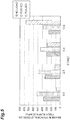
- FIG. 5 illustrates results obtained through simulations of stress applied to the bent portion BA of the optical fiber of the optical connection component.
- the horizontal axis indicates the inclination angle ⁇ , and four conditions including 0°, 2.5°, 5°, and 10° are presumed.
- the vertical axis indicates the maximum principal stress which is applied to the fiber surface of the bent portion and is obtained based on simulations when optical connection components including optical fibers manufactured at the inclination angles ⁇ are assembled as the optical module. Since the simulations were performed when the optical connection component was attached to the optical module, stress applied to the optical connection component in use was presumed.
- FIG. 5 illustrates results obtained through simulations of stress applied to the bent portion BA of the optical fiber of the optical connection component.
- the horizontal axis indicates the inclination angle ⁇ , and four conditions including 0°, 2.5°, 5°, and 10° are presumed.
- the vertical axis indicates the maximum principal stress which is applied to the fiber surface of the bent portion and is obtained based on simulations when optical connection components including
- the simulations were performed for each of the four inclination angles ⁇ presuming three conditions including a simulation with no-load (no-load), a simulation when pushed (pushed), and a simulation when pulled (pulled).
- the simulation with no-load was a simulation of a case using an optical fiber which was manufactured using design values and was not affected by a tolerance.
- the simulation when pushed was a simulation of a case using an optical fiber in which the fiber length was longer than the design value within the tolerance range.
- the simulation when pushed was based on the state in which the optical fiber was pushed from both ends when the optical connection component was attached to the optical module. In FIG.
- a state in which both ends of the optical fiber were pushed 0.5 mm compared to the simulation with no-load was set as the simulation when pushed.
- the simulation when pulled was a simulation of a case using an optical fiber in which the fiber length was shorter than the design value within the tolerance range.
- the simulation when pulled was based on the state in which the optical fiber was pulled compared to the simulation with no-load when the optical connection component was attached to the optical module.
- a state in which both ends of the optical fiber were pulled 0.5 mm compared to the simulation with no-load was set as the simulation when pulled.
- the inclination angle ⁇ of the region A in the end portion of the optical fiber 10 with respect to the direction perpendicular to the reference surface S, and the bending angle ⁇ of the bent portion BA relationships of 0° ⁇ 15° and 90° ⁇ + ⁇ are established.
- the inclination angle ⁇ with respect to the direction perpendicular to the reference surface S have a relationship of 0° ⁇ 15°.
- the inclination angle ⁇ is set to 0°, that is, in a case of a state in which the region A extends in the direction perpendicular to the reference surface S, when the fiber fixing part 20 of the optical connection component 1 is attached to the electronic substrate 100, there is a possibility that there may be more returning light due to reflection of light on the light input-output end surface of the optical fiber 10. In such a case, returning light can be curbed by causing the region A in the optical fiber 10 to be inclined such that the inclination angle ⁇ becomes wider than 0° in the direction perpendicular to the reference surface S.
- the inclination angle ⁇ and the bending angle ⁇ are controlled such that they satisfy the relationship of 90° ⁇ + ⁇ . Therefore, when the inclination angle ⁇ of the region A in the end portion of the optical fiber 10 with respect to the direction perpendicular to the reference surface S, and the bending angle ⁇ of the bent portion BA satisfy the foregoing relationships, stress applied to the bent portion BA can be reduced and performance of the optical connection component is also improved.
- optical connection component according to the present invention is not limited to the foregoing embodiment.
- the configuration and the shape of the optical connection component including the optical fibers 10, the fiber fixing part 20, and the connector 30 can be suitably changed.
Landscapes
- Physics & Mathematics (AREA)
- General Physics & Mathematics (AREA)
- Optics & Photonics (AREA)
- Optical Couplings Of Light Guides (AREA)
- Mechanical Coupling Of Light Guides (AREA)
Applications Claiming Priority (2)
| Application Number | Priority Date | Filing Date | Title |
|---|---|---|---|
| JP2016244527 | 2016-12-16 | ||
| PCT/JP2017/028296 WO2018109977A1 (fr) | 2016-12-16 | 2017-08-03 | Pièce de connexion optique |
Publications (2)
| Publication Number | Publication Date |
|---|---|
| EP3557295A1 true EP3557295A1 (fr) | 2019-10-23 |
| EP3557295A4 EP3557295A4 (fr) | 2019-12-11 |
Family
ID=62558287
Family Applications (1)
| Application Number | Title | Priority Date | Filing Date |
|---|---|---|---|
| EP17881851.4A Pending EP3557295A4 (fr) | 2016-12-16 | 2017-08-03 | Pièce de connexion optique |
Country Status (5)
| Country | Link |
|---|---|
| US (1) | US10739536B2 (fr) |
| EP (1) | EP3557295A4 (fr) |
| JP (1) | JP7052728B2 (fr) |
| CN (1) | CN110073260B (fr) |
| WO (1) | WO2018109977A1 (fr) |
Families Citing this family (4)
| Publication number | Priority date | Publication date | Assignee | Title |
|---|---|---|---|---|
| CN208044123U (zh) * | 2018-04-17 | 2018-11-02 | 武汉驿路通科技股份有限公司 | 一种用于垂直耦合的光纤阵列 |
| CN115280207B (zh) * | 2020-03-16 | 2024-04-26 | 住友电气工业株式会社 | 光纤连接部件以及光纤连接部件的制造方法 |
| WO2023119925A1 (fr) * | 2021-12-24 | 2023-06-29 | 住友電気工業株式会社 | Fibre optique courbée, procédé de fabrication de fibre optique courbée et composant de connexion optique |
| CN114415299B (zh) * | 2022-03-30 | 2022-06-24 | 深圳市埃尔法光电科技有限公司 | 一种光纤信号直导式光模块 |
Family Cites Families (27)
| Publication number | Priority date | Publication date | Assignee | Title |
|---|---|---|---|---|
| CA2138893C (fr) * | 1993-12-28 | 1999-12-07 | Hirotoshi Nagata | Boitier pour composants et fibres optiques et pour structures composites faites de ces elements |
| US6004639A (en) * | 1997-10-10 | 1999-12-21 | Fiberspar Spoolable Products, Inc. | Composite spoolable tube with sensor |
| JP4626535B2 (ja) * | 2006-02-22 | 2011-02-09 | 日立電線株式会社 | テープ状光ファイバケーブル |
| JP5224317B2 (ja) | 2006-11-20 | 2013-07-03 | 古河電気工業株式会社 | 光導波路部品および光導波路部品の製造方法 |
| JP4960297B2 (ja) * | 2008-03-05 | 2012-06-27 | 株式会社巴川製紙所 | 光学接続構造 |
| JP5290713B2 (ja) * | 2008-11-26 | 2013-09-18 | 古河電気工業株式会社 | 曲げコネクタ構造およびその作製方法 |
| JP5560567B2 (ja) | 2009-02-06 | 2014-07-30 | 日立金属株式会社 | 光ファイバ接続部品 |
| JP2010237266A (ja) | 2009-03-30 | 2010-10-21 | Hitachi Cable Ltd | 光コネクタ |
| CN101852898B (zh) * | 2009-03-30 | 2014-03-12 | 日立电线株式会社 | 光连接器及使用了光连接器的光纤模块 |
| JP5342343B2 (ja) | 2009-06-24 | 2013-11-13 | 古河電気工業株式会社 | 光コネクタ用フェルールの組立方法、組立治具および光コネクタ用フェルール構造 |
| JP5117471B2 (ja) | 2009-11-05 | 2013-01-16 | 古河電気工業株式会社 | 曲げコネクタ構造 |
| JP5599237B2 (ja) * | 2010-06-23 | 2014-10-01 | 矢崎総業株式会社 | 光コネクタ |
| CN102540361A (zh) * | 2010-12-24 | 2012-07-04 | 卓越光纤股份有限公司 | 一种光信号连接模块 |
| WO2012111650A1 (fr) | 2011-02-17 | 2012-08-23 | 古河電気工業株式会社 | Bague pour connecteur optique |
| JP5708465B2 (ja) * | 2011-12-12 | 2015-04-30 | 日立金属株式会社 | 光ファイバ接続部品及び光ファイバ接続モジュール |
| JP2015089489A (ja) * | 2013-11-07 | 2015-05-11 | 株式会社アライ・メッドフォトン研究所 | 医療用具及び光線治療装置 |
| JP6379642B2 (ja) * | 2014-05-07 | 2018-08-29 | 住友電気工業株式会社 | 光学装置の製造方法、光学装置及び光学コネクタユニット |
| WO2016006713A1 (fr) | 2014-07-11 | 2016-01-14 | 古河電気工業株式会社 | Connecteur à fibres optiques intégrées pouvant se cintrer et procédé de production de fibres optiques pouvant se cintrer |
| US20160291261A1 (en) * | 2015-04-01 | 2016-10-06 | SENKO Advanced Components (HK) Ltd. | Optical fiber connector with optical path direction changer |
| DE112015006766T5 (de) * | 2015-08-04 | 2018-04-19 | Sumitomo Electric Industries, Ltd. | Optische Verbindungskomponente |
| WO2017026072A1 (fr) | 2015-08-13 | 2017-02-16 | 住友電気工業株式会社 | Élément de raccord optique |
| CN205844579U (zh) * | 2015-12-30 | 2016-12-28 | 上海雍邑光电科技有限公司 | 一种能实现光传输方向发生弯折的光纤阵列 |
| JP6928848B2 (ja) * | 2016-03-31 | 2021-09-01 | 古河電気工業株式会社 | 光ファイバアレイ |
| CN109416434B (zh) * | 2016-07-15 | 2021-03-16 | 住友电气工业株式会社 | 制造光学连接部件的方法 |
| DE102016219620A1 (de) * | 2016-10-10 | 2018-04-12 | Continental Automotive Gmbh | Leiterplatte mit einem gebogenen Verbindungsabschnitt und Verfahren zum Testen bzw. Herstellen derselben sowie elektronisches Steuergerät und Verfahren zum Betrieb desselben |
| JP6958010B2 (ja) * | 2017-06-15 | 2021-11-02 | 住友電気工業株式会社 | 光接続部品の製造方法 |
| JP7024266B2 (ja) * | 2017-09-06 | 2022-02-24 | 住友電気工業株式会社 | 屈曲部を有する光ファイバの製造装置および製造方法 |
-
2017
- 2017-08-03 WO PCT/JP2017/028296 patent/WO2018109977A1/fr unknown
- 2017-08-03 JP JP2018556169A patent/JP7052728B2/ja active Active
- 2017-08-03 CN CN201780076766.XA patent/CN110073260B/zh active Active
- 2017-08-03 EP EP17881851.4A patent/EP3557295A4/fr active Pending
-
2019
- 2019-06-13 US US16/439,839 patent/US10739536B2/en active Active
Also Published As
| Publication number | Publication date |
|---|---|
| WO2018109977A1 (fr) | 2018-06-21 |
| CN110073260B (zh) | 2021-02-19 |
| CN110073260A (zh) | 2019-07-30 |
| EP3557295A4 (fr) | 2019-12-11 |
| US10739536B2 (en) | 2020-08-11 |
| JPWO2018109977A1 (ja) | 2019-10-24 |
| JP7052728B2 (ja) | 2022-04-12 |
| US20190293877A1 (en) | 2019-09-26 |
Similar Documents
| Publication | Publication Date | Title |
|---|---|---|
| US10739536B2 (en) | Optical connection component | |
| US9864150B2 (en) | Optical interconnection component | |
| JP6477890B2 (ja) | 光接続部品 | |
| EP3353585A1 (fr) | Dispositif d'interface optique ayant un guide d'onde courbe utilisant l'écriture laser et procédés de formation | |
| EP3171206B1 (fr) | Dispositifs d'interface optique et procédés utilisant des fibres optiques et un élément de support ayant une section coudée | |
| JP5952326B2 (ja) | 光レセプタクル | |
| US10539746B2 (en) | Optical connection component | |
| US20140079354A1 (en) | Method for producing optical connector and optical connector | |
| GB2328759A (en) | Metal coated optic fibre array on a grooved substrate | |
| JP5224317B2 (ja) | 光導波路部品および光導波路部品の製造方法 | |
| CN114600019B (zh) | 光纤连接部件以及光纤连接结构 | |
| JP2007256372A (ja) | 光ファイバ接続部品 | |
| JP2022065147A (ja) | 光レセプタクル及び光トランシーバ | |
| EP2573601B1 (fr) | Collimateur optique et connecteur optique utilisant ledit collimateur | |
| CN109143478B (zh) | 光学连接部件 | |
| GB2590285A (en) | Optical connection component | |
| JP5059715B2 (ja) | 光学接続構造 | |
| CN110824621A (zh) | 光学连接装置 | |
| JP6907866B2 (ja) | 光接続構造及び光配線部材 | |
| JP2023085697A (ja) | 光ファイバアレイ、及び、光接続構造体 | |
| JP2006220830A (ja) | ファイバピッチ規定保持具、光通信モジュール及び光ファイバ実装方法 | |
| KR20070030732A (ko) | 광 인터커넥트 장치 |
Legal Events
| Date | Code | Title | Description |
|---|---|---|---|
| STAA | Information on the status of an ep patent application or granted ep patent |
Free format text: STATUS: THE INTERNATIONAL PUBLICATION HAS BEEN MADE |
|
| PUAI | Public reference made under article 153(3) epc to a published international application that has entered the european phase |
Free format text: ORIGINAL CODE: 0009012 |
|
| STAA | Information on the status of an ep patent application or granted ep patent |
Free format text: STATUS: REQUEST FOR EXAMINATION WAS MADE |
|
| 17P | Request for examination filed |
Effective date: 20190709 |
|
| AK | Designated contracting states |
Kind code of ref document: A1 Designated state(s): AL AT BE BG CH CY CZ DE DK EE ES FI FR GB GR HR HU IE IS IT LI LT LU LV MC MK MT NL NO PL PT RO RS SE SI SK SM TR |
|
| AX | Request for extension of the european patent |
Extension state: BA ME |
|
| A4 | Supplementary search report drawn up and despatched |
Effective date: 20191111 |
|
| RIC1 | Information provided on ipc code assigned before grant |
Ipc: G02B 6/36 20060101AFI20191105BHEP Ipc: G02B 6/42 20060101ALI20191105BHEP Ipc: G02B 6/38 20060101ALI20191105BHEP |
|
| DAV | Request for validation of the european patent (deleted) | ||
| DAX | Request for extension of the european patent (deleted) | ||
| STAA | Information on the status of an ep patent application or granted ep patent |
Free format text: STATUS: EXAMINATION IS IN PROGRESS |
|
| 17Q | First examination report despatched |
Effective date: 20210518 |
|
| STAA | Information on the status of an ep patent application or granted ep patent |
Free format text: STATUS: EXAMINATION IS IN PROGRESS |