EP3557072B1 - Surveillance d'un dispositif de palier d'une pompe à vide - Google Patents
Surveillance d'un dispositif de palier d'une pompe à vide Download PDFInfo
- Publication number
- EP3557072B1 EP3557072B1 EP19159776.4A EP19159776A EP3557072B1 EP 3557072 B1 EP3557072 B1 EP 3557072B1 EP 19159776 A EP19159776 A EP 19159776A EP 3557072 B1 EP3557072 B1 EP 3557072B1
- Authority
- EP
- European Patent Office
- Prior art keywords
- vacuum pump
- temperature
- bearing
- pump
- bearing device
- Prior art date
- Legal status (The legal status is an assumption and is not a legal conclusion. Google has not performed a legal analysis and makes no representation as to the accuracy of the status listed.)
- Active
Links
Images


Classifications
-
- F—MECHANICAL ENGINEERING; LIGHTING; HEATING; WEAPONS; BLASTING
- F04—POSITIVE - DISPLACEMENT MACHINES FOR LIQUIDS; PUMPS FOR LIQUIDS OR ELASTIC FLUIDS
- F04D—NON-POSITIVE-DISPLACEMENT PUMPS
- F04D19/00—Axial-flow pumps
- F04D19/02—Multi-stage pumps
- F04D19/04—Multi-stage pumps specially adapted to the production of a high vacuum, e.g. molecular pumps
-
- F—MECHANICAL ENGINEERING; LIGHTING; HEATING; WEAPONS; BLASTING
- F04—POSITIVE - DISPLACEMENT MACHINES FOR LIQUIDS; PUMPS FOR LIQUIDS OR ELASTIC FLUIDS
- F04D—NON-POSITIVE-DISPLACEMENT PUMPS
- F04D27/00—Control, e.g. regulation, of pumps, pumping installations or pumping systems specially adapted for elastic fluids
- F04D27/001—Testing thereof; Determination or simulation of flow characteristics; Stall or surge detection, e.g. condition monitoring
-
- F—MECHANICAL ENGINEERING; LIGHTING; HEATING; WEAPONS; BLASTING
- F04—POSITIVE - DISPLACEMENT MACHINES FOR LIQUIDS; PUMPS FOR LIQUIDS OR ELASTIC FLUIDS
- F04D—NON-POSITIVE-DISPLACEMENT PUMPS
- F04D27/00—Control, e.g. regulation, of pumps, pumping installations or pumping systems specially adapted for elastic fluids
- F04D27/02—Surge control
- F04D27/0292—Stop safety or alarm devices, e.g. stop-and-go control; Disposition of check-valves
-
- F—MECHANICAL ENGINEERING; LIGHTING; HEATING; WEAPONS; BLASTING
- F04—POSITIVE - DISPLACEMENT MACHINES FOR LIQUIDS; PUMPS FOR LIQUIDS OR ELASTIC FLUIDS
- F04D—NON-POSITIVE-DISPLACEMENT PUMPS
- F04D29/00—Details, component parts, or accessories
- F04D29/05—Shafts or bearings, or assemblies thereof, specially adapted for elastic fluid pumps
- F04D29/056—Bearings
Definitions
- the present invention relates to a vacuum pump, in particular a turbo-molecular pump, with at least one pump stage which comprises at least one rotor which is rotatably supported by means of at least one bearing device.
- Such vacuum pumps are known in principle and are widely used, for example in industry and / or in the scientific field. It is not only their (operating) costs, performance or size that are essential factors that are important for the respective user. They also need to be reliable as failure can cause damage to the vacuum equipment they are associated with.
- the JP S62 282194 A and the EP 0 851 127 A2 each disclose a vacuum pump with the features of the preamble of claim 1.
- a vacuum pump having the features of claim 1 is provided.
- the determined operating state often deviates from a normal operating state characteristic of the respective operating mode. Detection of such a deviation can then be used to initiate appropriate countermeasures.
- the temperature of the storage facility can be determined directly on it. However, it is also possible to determine the temperature in the vicinity of the storage facility, in particular on components that are in close - preferably direct - contact with the storage facility. When determining the temperature in the immediate vicinity of the storage facility, it can be assumed that the determined value essentially corresponds to that which would be determined directly at the storage facility.
- the second sensor device determines the state of the vacuum pump at a spatial distance in order to obtain at least one additional temperature that is not or only slightly influenced by the state of the storage device.
- temperatures are thus compared which, on the one hand, are strongly and, on the other hand, little or essentially not at all influenced by the state of the storage facility. This comparison allows conclusions to be drawn about the operating state of the storage facility and / or its change over time. When comparing the temperatures, their discrete values and / or their change over time can be taken into account.
- control device recognizes on the basis of the comparison that the vacuum pump is functioning properly when the two different temperatures change coherently within predetermined limits.
- the pump is started up, an increase in both temperatures can be expected. As soon as they diverge, however, this can be interpreted as an indication of impending bearing damage.
- other scenarios of the development of the temperatures over time are also conceivable which speak for or against a change in the operating state of the storage facility.
- more than two sensor devices can also be provided, the measurement data of which are used to determine the operating state of the bearing device in order to increase the reliability of the analysis and / or to meet special requirements of the pump.
- the first and / or the second sensor device comprise a temperature sensor.
- a damaged or worn bearing often shows damage to components of the bearing (e.g. damage to the raceways of the balls and / or to the ball cage in the case of a ball bearing), which leads to increased bearing friction, which in turn results in an increase in temperature and / or changes the vibration behavior of the bearing is reflected.
- the construction of the vacuum pump can be optimized to achieve a certain value of the thermal conductivity between the temperature sensors. With an optimal thermal resistance between the sensors, the evaluation of the determined temperature spread is simplified.
- the bearing device can comprise at least one roller bearing, in particular at least one ball bearing.
- the concept of the invention can also be used with other types of bearings, e.g. with slide bearings.
- the first sensor device can be arranged in such a way that the temperature of a component of the vacuum pump can be determined - directly or indirectly - which the bearing device receives.
- a temperature sensor is provided which detects the temperature of a bearing mount or a component adjacent to the bearing device.
- the temperature of the storage facility can also be measured directly on it.
- a conventional temperature sensor or an IR sensor can be used, for example.
- the vacuum pump comprises an active cooling device which is provided at least for cooling a component of the vacuum pump whose operating parameters can be determined by the second sensor device.
- This component can be a housing component, for example.
- the bearing device is received by a first component of the vacuum pump, which is formed separately from a second component of the vacuum pump, in particular a housing component (e.g. a lower part) of the vacuum pump, to which the second sensor device is assigned.
- a first component of the vacuum pump which is formed separately from a second component of the vacuum pump, in particular a housing component (e.g. a lower part) of the vacuum pump, to which the second sensor device is assigned.
- the first and second components are preferably connected to one another in a thermally conductive manner.
- the first and the second sensor device or their measuring area are arranged on a component, e.g. on a lower part of the pump.
- the sensor devices are spatially spaced, i.e. the first sensor device is arranged close to the bearing, while the second sensor device is arranged remote from the bearing.
- the present invention also relates to a method according to claim 6.
- the comparison can be preceded by data filtering and / or conversion, or it can include these or similar methods. It can also be provided that stability criteria are taken into account in the data processing and / or analysis. The aim of these measures is, among other things, to eliminate irrelevant (e.g. short-term) fluctuations in the data that could paint a wrong picture of the condition of the warehouse.
- the first sensor device is either arranged in such a way that it can measure the temperature of the storage device directly.
- the measurement is carried out in the immediate vicinity of the storage facility. It can then be assumed that the measured value essentially corresponds to that which would be obtained with a direct measurement.
- the second sensor device is intended to supply a value of an operating state that is little or hardly influenced by the state of the bearing device. It is therefore determined at some distance from the storage facility.
- a temperature of the storage device or a neighboring component that is in direct or direct contact with the storage device and a temperature of a section of a housing of the vacuum pump are used as the basis for determining the operating state of the storage device.
- the comparison of the temperature of the storage device and the temperature of the vacuum pump includes the formation of a comparison parameter. If the comparison parameter falls below and / or exceeds a predefined or learned threshold value, a malfunction is detected.
- a parameter space that corresponds to a normal or abnormal state can also be defined for the comparison parameter.
- the comparison of the temperature of the storage device and the temperature of the vacuum pump can include the formation of a difference in temperature, a malfunction being determined if a predefined or learned threshold value of the difference is exceeded.
- the comparison can, however, also include the formation of a quotient or the like
- a warning signal can be issued.
- the operation of the vacuum pump is automatically intervened - e.g. by the control device - if the malfunction occurs. For example, the pump is stopped gently or abruptly, or the speed of the pump is reduced in order to put it into a "safe" operating mode.
- the reaction to the occurrence of the incident can be selected depending on the determined severity of the incident.
- the operating state of the vacuum pump is only determined when the temperature of the vacuum pump reaches a static or quasi-static value or range of values Has.
- the temperature distribution in the vacuum pump only settles after some time when the pump is started up.
- the specific temperatures of the sensor devices may therefore still provide an image that does not necessarily allow reliable conclusions to be drawn about the actual condition of the storage device.
- the corresponding analysis is only started or the corresponding measurement data are only taken into account when the pump has reached a stable state in order to minimize the probability of false alarms.
- the temperatures of the storage device and / or the vacuum pump are also influenced by factors that not only depend on the condition of the storage device and / or, for example, a speed of the pump.
- the age of the pump, a running time after the last service interval, a "history" of the pump (how long was it operated at which speeds or in which operating modes), the age of the lubricant used, etc. also influence the temperatures during operation the pump. The same applies to external factors such as mechanical loading and / or vibration loading on the pump and / or temperature loading on the pump.
- the threshold value described above is adapted accordingly.
- the data obtained when determining the operating state of the storage facility can also be used to determine a point in time at which maintenance of the pump or the storage facility should be carried out. The user can also see the remaining time of the maintenance interval.
- the data mentioned can be used to optimize maintenance, since the maintenance intervals can be adapted as required and depending on the intensity of use of the pump.
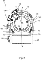
- the turbo-molecular pump 111 shown comprises a pump inlet 115 which is surrounded by an inlet flange 113 and to which a recipient (not shown) can be connected in a manner known per se.
- the gas from the recipient can be sucked out of the recipient via the pump inlet 115 and conveyed through the pump to a pump outlet 117 to which a backing pump, such as a rotary vane pump, can be connected.
- the inlet flange 113 forms according to FIG Fig. 1 the upper end of the housing 119 of the vacuum pump 111.
- the housing 119 comprises a lower part 121 on which an electronics housing 123 is arranged laterally. Electrical and / or electronic components of the vacuum pump 111 are accommodated in the electronics housing 123, for example for operating an electric motor 125 arranged in the vacuum pump. A plurality of connections 127 for accessories are provided on the electronics housing 123.
- a data interface 129 for example in accordance with the RS485 standard, and a power supply connection 131 are arranged on the electronics housing 123.
- a flood inlet 133 in particular in the form of a flood valve, is provided on the housing 119 of the turbo molecular pump 111, via which the vacuum pump 111 can be flooded.
- a sealing gas connection 135, which is also referred to as a purge gas connection via which purge gas to protect the electric motor 125 (see, for example, FIG Fig. 3 ) can be brought into the engine compartment 137, in which the electric motor 125 in the vacuum pump 111 is accommodated, before the gas conveyed by the pump.
- Two coolant connections 139 are also arranged in the lower part 121, one of the coolant connections being provided as an inlet and the other coolant connection being provided as an outlet for coolant which can be passed into the vacuum pump for cooling purposes.
- the lower side 141 of the vacuum pump can serve as a standing surface, so that the vacuum pump 111 can be operated standing on the lower side 141.
- the vacuum pump 111 can, however, also be attached to a recipient via the inlet flange 113 and can thus be operated in a suspended manner, as it were.
- the vacuum pump 111 can be designed in such a way that it can also be put into operation when it is oriented in a different way than in FIG Fig. 1 is shown.
- Embodiments of the vacuum pump can also be implemented in which the underside 141 cannot be arranged facing downwards, but facing to the side or facing upwards.
- a bearing cap 145 is attached to the underside 141.
- Fastening bores 147 are also arranged on the underside 141, via which the pump 111 can be fastened to a support surface, for example.
- a coolant line 148 is shown, in which the coolant introduced and discharged via the coolant connections 139 can circulate.
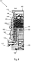
- the vacuum pump comprises several process gas pump stages for conveying the process gas present at the pump inlet 115 to the pump outlet 117.
- a rotor 149 is arranged in the housing 119 and has a rotor shaft 153 rotatable about an axis of rotation 151.
- the turbo-molecular pump 111 comprises several turbo-molecular pump stages connected in series with one another with several radial rotor disks 155 fastened to the rotor shaft 153 and stator disks 157 arranged between the rotor disks 155 and fixed in the housing 119.
- a rotor disk 155 and an adjacent stator disk 157 each form a turbomolecular one Pumping stage.
- the stator disks 157 are held at a desired axial distance from one another by spacer rings 159.
- the vacuum pump also comprises Holweck pump stages which are arranged one inside the other in the radial direction and are connected in series with one another for effective pumping.
- the rotor of the Holweck pump stages comprises a rotor hub 161 arranged on the rotor shaft 153 and two cylinder-jacket-shaped Holweck rotor sleeves 163, 165 which are attached to the rotor hub 161 and carried by the latter, which are oriented coaxially to the axis of rotation 151 and nested in one another in the radial direction.
- two cylinder jacket-shaped Holweck stator sleeves 167, 169 are provided, which are also oriented coaxially to the axis of rotation 151 and, viewed in the radial direction, are nested inside one another.
- the active pumping surfaces of the Holweck pump stages are formed by the jacket surfaces, that is to say by the radial inner and / or outer surfaces, of the Holweck rotor sleeves 163, 165 and the Holweck stator sleeves 167, 169.
- the radial inner surface of the outer Holweck stator sleeve 167 lies opposite the radial outer surface of the outer Holweck rotor sleeve 163 with the formation of a radial Holweck gap 171 and with this forms the first Holweck pumping stage following the turbo molecular pumps.
- the radial inner surface of the outer Holweck rotor sleeve 163 faces the radial outer surface of the inner Holweck stator sleeve 169 with the formation of a radial Holweck gap 173 and with this forms a second Holweck pumping stage.
- the radial inner surface of the inner Holweck stator sleeve 169 lies opposite the radial outer surface of the inner Holweck rotor sleeve 165 with the formation of a radial Holweck gap 175 and with this forms the third Holweck pumping stage.
- a radially running channel can be provided, via which the radially outer Holweck gap 171 is connected to the central Holweck gap 173.
- a radially running channel can be provided at the upper end of the inner Holweck stator sleeve 169, via which the middle Holweck gap 173 is connected to the radially inner Holweck gap 175.
- the nested Holweck pump stages are connected in series with one another.
- the radially inner Holweck rotor sleeve 165 can furthermore be provided with a connection channel 179 to outlet 117.
- the aforementioned pump-active surfaces of the Holweck stator sleeves 163, 165 each have a plurality of Holweck grooves running helically around the axis of rotation 151 in the axial direction, while the opposite lateral surfaces of the Holweck rotor sleeves 163, 165 are smooth and the gas for operating the Drive vacuum pump 111 in the Holweck grooves.
- a roller bearing 181 in the area of the pump outlet 117 and a permanent magnet bearing 183 in the area of the pump inlet 115 are provided for the rotatable mounting of the rotor shaft 153.
- a conical injection molded nut 185 is provided on the rotor shaft 153 with an outer diameter that increases towards the roller bearing 181.
- the injection-molded nut 185 is in sliding contact with at least one stripper of an operating medium store.
- the operating medium reservoir comprises several absorbent discs 187 stacked on top of one another, which are impregnated with an operating medium for the roller bearing 181, for example with a lubricant.
- the operating medium is transferred by capillary action from the operating medium reservoir via the scraper to the rotating injection nut 185 and, as a result of the centrifugal force, is conveyed along the injection nut 185 in the direction of the increasing outer diameter of the injection nut 185 to the roller bearing 181, where it eg fulfills a lubricating function.
- the roller bearing 181 and the operating medium store are enclosed in the vacuum pump by a trough-shaped insert 189 and the bearing cover 145.
- the permanent magnetic bearing 183 comprises a rotor-side bearing half 191 and a stator-side bearing half 193, each of which is a ring stack of several permanent magnetic rings 195, 197 stacked on top of one another in the axial direction.
- the ring magnets 195, 197 are opposite one another with the formation of a radial bearing gap 199, the rotor-side ring magnets 195 being arranged radially on the outside and the stator-side ring magnets 197 being arranged radially on the inside.
- the magnetic field present in the bearing gap 199 causes magnetic repulsive forces between the ring magnets 195, 197, which cause the rotor shaft 153 to be supported radially.
- the rotor-side ring magnets 195 are carried by a carrier section 201 of the rotor shaft 153 which surrounds the ring magnets 195 radially on the outside.
- the stator-side ring magnets 197 are carried by a stator-side support section 203 which extends through the ring magnets 197 and is suspended from radial struts 205 of the housing 119.
- the ring magnets 195 on the rotor side are fixed parallel to the axis of rotation 151 by a cover element 207 coupled to the carrier section 203.
- the stator-side ring magnets 197 are fixed parallel to the axis of rotation 151 in one direction by a fastening ring 209 connected to the carrier section 203 and a fastening ring 211 connected to the carrier section 203.
- a plate spring 213 can also be provided between the fastening ring 211 and the ring magnet 197.
- An emergency or retainer bearing 215 is provided inside the magnetic bearing, which runs empty during normal operation of the vacuum pump 111 without contact and only comes into engagement with an excessive radial deflection of the rotor 149 relative to the stator to create a radial stop for the rotor 149 to form, since a collision of the rotor-side structures with the stator-side structures is prevented.
- the backup bearing 215 is designed as an unlubricated roller bearing and forms a radial gap with the rotor 149 and / or the stator, which has the effect that the backup bearing 215 is disengaged during normal pumping operation.
- the radial deflection at which the safety bearing 215 engages is dimensioned large enough so that the safety bearing 215 is in normal operation of the vacuum pump does not come into engagement, and at the same time small enough that a collision of the rotor-side structures with the stator-side structures is prevented under all circumstances.
- the vacuum pump 111 comprises the electric motor 125 for rotatingly driving the rotor 149.
- the armature of the electric motor 125 is formed by the rotor 149, the rotor shaft 153 of which extends through the motor stator 217.
- a permanent magnet arrangement can be arranged radially on the outside or embedded in the section of the rotor shaft 153 extending through the motor stator 217.
- the motor stator 217 is fixed in the housing within the motor compartment 137 provided for the electric motor 125.
- a sealing gas which is also referred to as a flushing gas and which can be air or nitrogen, for example, can enter the engine compartment 137 via the sealing gas connection 135.
- the electric motor 125 can be protected from process gas, e.g. from corrosive components of the process gas, via the sealing gas.
- the engine compartment 137 can also be evacuated via the pump outlet 117, i.e. in the engine compartment 137 there is at least approximately the vacuum pressure produced by the backing pump connected to the pump outlet 117.
- a so-called labyrinth seal 223, known per se, can also be provided between the rotor hub 161 and a wall 221 delimiting the engine compartment 137, in particular in order to achieve a better sealing of the motor compartment 217 from the Holweck pump stages located radially outside.
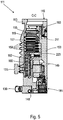
- Fig. 6 shows an embodiment according to the invention of a turbomolecular pump, in which, however, areas are given by way of example in which the respective measuring range of the first and second sensor devices described at the outset lie.
- at least one temperature sensor (not shown) is provided which is arranged in such a way that it can determine the temperature prevailing in an area T1.
- the area T1 is assigned to the insert 189, which receives the ball bearing 181.
- a temperature measurement can take place in an area T1 '.
- the area T1 ′ lies in the lower part 121 and is in direct contact with the insert 189.
- the temperature sensor (s) measure - directly or indirectly - the temperatures prevailing there, which enables direct conclusions to be drawn about the temperature of the roller bearing 181, since the areas T1 and T1 'are in spatial proximity to the bearing 181.
- a normal temperature rise can be concluded, which is determined, for example, by the operating mode of the pump and / or by external factors.
- the operating mode of the pump In the event of an unusual spread in the areas T1, T1 'on the one hand and in the area T2 on the other hand measured data and / or in the case of a temperature rise only in the areas T1, T1 ', this can be due to increasing wear of the bearing 181 or to an impending damage.
- a control device of the pump which records and evaluates the data mentioned, recognizes this and (automatically) initiates countermeasures (e.g. warning signal, stopping the pump, changing the operating mode, adjusting the maintenance interval, etc.).
- the area T2 and the areas T1, T1 ' are thermally coupled in order to enable temperature equalization in normal operation. With proper operation of the pump, a static or quasi-static temperature distribution is established after a certain time at a given load condition.
- the state of the bearing 181 is preferably not monitored until such a state has been reached in order to minimize the risk of false alarms.
- Active cooling for example water cooling
- the cooling increases the spread between the temperature values measured in the areas T1, T1 'on the one hand and T2 on the other hand, which simplifies data analysis.
- a corresponding cooling device is in Fig. 6 only one coolant connection 225 is shown.
- Exemplary spreads are - depending on the cooling - temperature differences of 1 ° C to 5 ° C in a normal storage condition. In the event of impending bearing damage, the spread increases to values of e.g. more than 5 ° C, more than 6 ° C, more than 15 ° C or even larger values.
- the concept of the invention is not limited to turbo molecular pumps, but can also be used with other types of pumps.
Landscapes
- Engineering & Computer Science (AREA)
- Mechanical Engineering (AREA)
- General Engineering & Computer Science (AREA)
- Non-Positive Displacement Air Blowers (AREA)
Claims (11)
- Pompe à vide, en particulier pompe turbomoléculaire, comprenant au moins un étage de pompage qui comprend au moins un rotor monté de façon rotative au moyen d'au moins un dispositif formant palier, un premier dispositif capteur qui est disposé au voisinage du dispositif formant palier et qui permet de déterminer une température du dispositif formant palier, et un second dispositif capteur qui est disposé à distance du dispositif formant palier et qui permet de déterminer une température de la pompe à vide, en particulier une température d'un carter de la pompe à vide,
dans laquelle
il est prévu un dispositif de commande qui est réalisé et conçu pour comparer mutuellement la température du dispositif formant palier et la température de la pompe à vide et pour déterminer un état de fonctionnement du dispositif formant palier sur la base de la comparaison,
caractérisée en ce que
la pompe à vide comprend un dispositif de refroidissement actif qui est prévu au moins pour refroidir un composant de la pompe à vide dont la température peut être déterminée par le second dispositif capteur. - Pompe à vide selon la revendication 1,
caractérisée en ce que
les premier et second dispositifs capteurs comprennent un capteur de température. - Pompe à vide selon l'une au moins des revendications précédentes,
caractérisée en ce que
le dispositif formant palier comprend au moins un roulement, en particulier au moins un roulement à billes. - Pompe à vide selon l'une au moins des revendications précédentes,
caractérisée en ce que
le premier dispositif capteur est disposé de telle sorte que la température d'un composant, recevant le dispositif formant palier, de la pompe à vide peut être déterminée directement ou indirectement. - Pompe à vide selon la revendication 4,
caractérisée en ce que
le dispositif formant palier est reçu par un premier composant de la pompe à vide, qui est réalisé séparément d'un second composant de la pompe à vide, en particulier séparément d'un composant de carter de la pompe à vide, auquel est associé le second dispositif capteur, en particulier les premier et second composants étant couplés l'un à l'autre de manière thermoconductrice. - Procédé pour faire fonctionner une pompe à vide selon l'une au moins des revendications 1 à 5,
dans lequel
la température du dispositif formant palier et la température de la pompe à vide sont comparées l'une à l'autre, et un état de fonctionnement du dispositif formant palier est déterminé sur la base de la comparaison. - Procédé selon la revendication 6,
caractérisé en ce que
la comparaison de la température du dispositif formant palier et de la température de la pompe à vide inclut la formation d'un paramètre de comparaison, et en ce que
lorsque l'on passe au-dessous et/ou au-dessus d'une valeur seuil du paramètre de comparaison, on constate un dysfonctionnement. - Procédé selon la revendication 7,
caractérisé en ce que
la comparaison de la température du dispositif formant palier et de la température de la pompe à vide inclut la formation d'une différence de températures, et en ce que
lorsque l'on passe au-dessus d'une valeur seuil de la différence, on constate un dysfonctionnement. - Procédé selon la revendication 7 ou 8,
caractérisé en ce que
lorsque le dysfonctionnement est constaté, un signal d'avertissement est émis et/ou il se produit une intervention automatique dans le fonctionnement de la pompe à vide. - Procédé selon l'une au moins des revendications 6 à 9,
caractérisé en ce que
l'état de fonctionnement de la pompe à vide n'est déterminé que lorsque la température de la pompe à vide a atteint une valeur ou une plage de valeurs statique ou quasi-statique. - Procédé selon l'une au moins des revendications 6 à 10,
caractérisé en ce que
d'autres facteurs sont pris en compte lors de la détermination de l'état de fonctionnement de la pompe à vide, en particulier des paramètres externes et/ou internes, de préférence un temps de fonctionnement et/ou un âge de la pompe à vide, une charge mécanique externe de la pompe à vide, une charge de température externe de la pompe à vide et/ou un mode de fonctionnement de la pompe à vide.
Priority Applications (2)
| Application Number | Priority Date | Filing Date | Title |
|---|---|---|---|
| EP19159776.4A EP3557072B1 (fr) | 2019-02-27 | 2019-02-27 | Surveillance d'un dispositif de palier d'une pompe à vide |
| JP2020028168A JP7239510B2 (ja) | 2019-02-27 | 2020-02-21 | 真空ポンプ |
Applications Claiming Priority (1)
| Application Number | Priority Date | Filing Date | Title |
|---|---|---|---|
| EP19159776.4A EP3557072B1 (fr) | 2019-02-27 | 2019-02-27 | Surveillance d'un dispositif de palier d'une pompe à vide |
Publications (2)
| Publication Number | Publication Date |
|---|---|
| EP3557072A1 EP3557072A1 (fr) | 2019-10-23 |
| EP3557072B1 true EP3557072B1 (fr) | 2021-02-24 |
Family
ID=65628702
Family Applications (1)
| Application Number | Title | Priority Date | Filing Date |
|---|---|---|---|
| EP19159776.4A Active EP3557072B1 (fr) | 2019-02-27 | 2019-02-27 | Surveillance d'un dispositif de palier d'une pompe à vide |
Country Status (2)
| Country | Link |
|---|---|
| EP (1) | EP3557072B1 (fr) |
| JP (1) | JP7239510B2 (fr) |
Families Citing this family (2)
| Publication number | Priority date | Publication date | Assignee | Title |
|---|---|---|---|---|
| EP4174321B1 (fr) * | 2021-10-29 | 2024-01-17 | Pfeiffer Vacuum Technology AG | Pompe à vide |
| GB2619964B (en) * | 2022-06-24 | 2024-12-25 | Edwards Ltd | Method for detection of a bearing condition of a vacuum pump |
Family Cites Families (7)
| Publication number | Priority date | Publication date | Assignee | Title |
|---|---|---|---|---|
| JPS62282194A (ja) * | 1986-05-30 | 1987-12-08 | Mitsubishi Electric Corp | タ−ボ分子ポンプ装置 |
| IT1289811B1 (it) * | 1996-12-27 | 1998-10-16 | Varian Spa | Metodo ed apparato di diagnosi per pompa da vuoto. |
| JPH10306790A (ja) * | 1997-05-01 | 1998-11-17 | Daikin Ind Ltd | 分子ポンプ |
| DE102006034478A1 (de) | 2006-07-26 | 2008-01-31 | Oerlikon Leybold Vacuum Gmbh | Verfahren zur Ermittlung einer Aussage über einen Zustand einer Turbomolekularpumpe sowie eine Turbomolekularpumpe |
| KR101629979B1 (ko) * | 2008-07-14 | 2016-06-13 | 에드워즈 가부시키가이샤 | 진공 펌프 |
| JP6287475B2 (ja) | 2014-03-28 | 2018-03-07 | 株式会社島津製作所 | 真空ポンプ |
| JP2018159340A (ja) * | 2017-03-23 | 2018-10-11 | 株式会社島津製作所 | 真空ポンプの制御装置、およびポンプ装置 |
-
2019
- 2019-02-27 EP EP19159776.4A patent/EP3557072B1/fr active Active
-
2020
- 2020-02-21 JP JP2020028168A patent/JP7239510B2/ja active Active
Also Published As
| Publication number | Publication date |
|---|---|
| JP2020139504A (ja) | 2020-09-03 |
| JP7239510B2 (ja) | 2023-03-14 |
| EP3557072A1 (fr) | 2019-10-23 |
Similar Documents
| Publication | Publication Date | Title |
|---|---|---|
| EP3653885B1 (fr) | Procédé de détermination d'une information d'état dans un appareil sous vide | |
| EP3808988B1 (fr) | Pompe à vide et procédé de surveillance d'une pompe à vide | |
| EP3832141B1 (fr) | Procédé de fonctionnement d'une pompe à vide | |
| EP3557072B1 (fr) | Surveillance d'un dispositif de palier d'une pompe à vide | |
| EP3557073A1 (fr) | Pompe à vide | |
| EP3657021A1 (fr) | Pompe à vide | |
| EP3438460B1 (fr) | Pompe à vide | |
| EP3112687B1 (fr) | Détection de la circulation d'un gaz auxiliaire qui est injecté dans une pompe à vide | |
| EP3660317B1 (fr) | Appareil à vide | |
| EP4144994B1 (fr) | Dispositif et procédé d'évaluation d'un palier magnétique | |
| EP3135932B1 (fr) | Pompe à vide et palier à aimant permanent | |
| EP3636933B1 (fr) | Procédé de détermination d'une température utilisant un capteur infrarouge | |
| EP4137699B1 (fr) | Appareil à vide et procédé de fonctionnement d'un tel appareil à vide | |
| EP3683449A1 (fr) | Palier magnétique et appareil sous vide | |
| EP3536965B1 (fr) | Pompe à vide dans laquelle le support d'un palier à roulement a une rigidité et/ou un amortissement réglable(s) | |
| EP3633204B1 (fr) | Pompe à vide | |
| EP2927501B1 (fr) | Procédé et système pour la détermination et l'évaluation du sens d'encastrement d'un dispositif | |
| EP3611383B1 (fr) | Réglage de vitesse de rotation d'un rotor d'une pompe à vide | |
| EP3628873B1 (fr) | Logement de rotor | |
| EP3926174B1 (fr) | Pompe à vide | |
| EP3536966B1 (fr) | Appareil à vide | |
| EP3736447A1 (fr) | Pompe à vide et procédé de surveillance d'une pompe à vide | |
| EP3557071B1 (fr) | Pompe à vide et procédé de fonctionnement d'une telle pompe à vide | |
| EP4174321B1 (fr) | Pompe à vide | |
| EP4269805A1 (fr) | Pompe à vide |
Legal Events
| Date | Code | Title | Description |
|---|---|---|---|
| PUAI | Public reference made under article 153(3) epc to a published international application that has entered the european phase |
Free format text: ORIGINAL CODE: 0009012 |
|
| STAA | Information on the status of an ep patent application or granted ep patent |
Free format text: STATUS: THE APPLICATION HAS BEEN PUBLISHED |
|
| AK | Designated contracting states |
Kind code of ref document: A1 Designated state(s): AL AT BE BG CH CY CZ DE DK EE ES FI FR GB GR HR HU IE IS IT LI LT LU LV MC MK MT NL NO PL PT RO RS SE SI SK SM TR |
|
| AX | Request for extension of the european patent |
Extension state: BA ME |
|
| STAA | Information on the status of an ep patent application or granted ep patent |
Free format text: STATUS: REQUEST FOR EXAMINATION WAS MADE |
|
| 17P | Request for examination filed |
Effective date: 20200423 |
|
| RBV | Designated contracting states (corrected) |
Designated state(s): AL AT BE BG CH CY CZ DE DK EE ES FI FR GB GR HR HU IE IS IT LI LT LU LV MC MK MT NL NO PL PT RO RS SE SI SK SM TR |
|
| GRAP | Despatch of communication of intention to grant a patent |
Free format text: ORIGINAL CODE: EPIDOSNIGR1 |
|
| STAA | Information on the status of an ep patent application or granted ep patent |
Free format text: STATUS: GRANT OF PATENT IS INTENDED |
|
| INTG | Intention to grant announced |
Effective date: 20200918 |
|
| RIN1 | Information on inventor provided before grant (corrected) |
Inventor name: STOLL, TOBIAS Inventor name: SCHNARR,JOHANNES Inventor name: BOETTCHER, JOCHEN Inventor name: SCHWEIGHOEFER, MICHAEL |
|
| GRAS | Grant fee paid |
Free format text: ORIGINAL CODE: EPIDOSNIGR3 |
|
| GRAA | (expected) grant |
Free format text: ORIGINAL CODE: 0009210 |
|
| STAA | Information on the status of an ep patent application or granted ep patent |
Free format text: STATUS: THE PATENT HAS BEEN GRANTED |
|
| AK | Designated contracting states |
Kind code of ref document: B1 Designated state(s): AL AT BE BG CH CY CZ DE DK EE ES FI FR GB GR HR HU IE IS IT LI LT LU LV MC MK MT NL NO PL PT RO RS SE SI SK SM TR |
|
| REG | Reference to a national code |
Ref country code: CH Ref legal event code: EP |
|
| REG | Reference to a national code |
Ref country code: DE Ref legal event code: R096 Ref document number: 502019000833 Country of ref document: DE |
|
| REG | Reference to a national code |
Ref country code: AT Ref legal event code: REF Ref document number: 1364776 Country of ref document: AT Kind code of ref document: T Effective date: 20210315 |
|
| REG | Reference to a national code |
Ref country code: IE Ref legal event code: FG4D Free format text: LANGUAGE OF EP DOCUMENT: GERMAN |
|
| REG | Reference to a national code |
Ref country code: LT Ref legal event code: MG9D |
|
| REG | Reference to a national code |
Ref country code: NL Ref legal event code: MP Effective date: 20210224 |
|
| PG25 | Lapsed in a contracting state [announced via postgrant information from national office to epo] |
Ref country code: BG Free format text: LAPSE BECAUSE OF FAILURE TO SUBMIT A TRANSLATION OF THE DESCRIPTION OR TO PAY THE FEE WITHIN THE PRESCRIBED TIME-LIMIT Effective date: 20210524 Ref country code: HR Free format text: LAPSE BECAUSE OF FAILURE TO SUBMIT A TRANSLATION OF THE DESCRIPTION OR TO PAY THE FEE WITHIN THE PRESCRIBED TIME-LIMIT Effective date: 20210224 Ref country code: GR Free format text: LAPSE BECAUSE OF FAILURE TO SUBMIT A TRANSLATION OF THE DESCRIPTION OR TO PAY THE FEE WITHIN THE PRESCRIBED TIME-LIMIT Effective date: 20210525 Ref country code: FI Free format text: LAPSE BECAUSE OF FAILURE TO SUBMIT A TRANSLATION OF THE DESCRIPTION OR TO PAY THE FEE WITHIN THE PRESCRIBED TIME-LIMIT Effective date: 20210224 Ref country code: NO Free format text: LAPSE BECAUSE OF FAILURE TO SUBMIT A TRANSLATION OF THE DESCRIPTION OR TO PAY THE FEE WITHIN THE PRESCRIBED TIME-LIMIT Effective date: 20210524 Ref country code: PT Free format text: LAPSE BECAUSE OF FAILURE TO SUBMIT A TRANSLATION OF THE DESCRIPTION OR TO PAY THE FEE WITHIN THE PRESCRIBED TIME-LIMIT Effective date: 20210624 Ref country code: LT Free format text: LAPSE BECAUSE OF FAILURE TO SUBMIT A TRANSLATION OF THE DESCRIPTION OR TO PAY THE FEE WITHIN THE PRESCRIBED TIME-LIMIT Effective date: 20210224 |
|
| PG25 | Lapsed in a contracting state [announced via postgrant information from national office to epo] |
Ref country code: NL Free format text: LAPSE BECAUSE OF FAILURE TO SUBMIT A TRANSLATION OF THE DESCRIPTION OR TO PAY THE FEE WITHIN THE PRESCRIBED TIME-LIMIT Effective date: 20210224 Ref country code: PL Free format text: LAPSE BECAUSE OF FAILURE TO SUBMIT A TRANSLATION OF THE DESCRIPTION OR TO PAY THE FEE WITHIN THE PRESCRIBED TIME-LIMIT Effective date: 20210224 Ref country code: LV Free format text: LAPSE BECAUSE OF FAILURE TO SUBMIT A TRANSLATION OF THE DESCRIPTION OR TO PAY THE FEE WITHIN THE PRESCRIBED TIME-LIMIT Effective date: 20210224 Ref country code: RS Free format text: LAPSE BECAUSE OF FAILURE TO SUBMIT A TRANSLATION OF THE DESCRIPTION OR TO PAY THE FEE WITHIN THE PRESCRIBED TIME-LIMIT Effective date: 20210224 Ref country code: SE Free format text: LAPSE BECAUSE OF FAILURE TO SUBMIT A TRANSLATION OF THE DESCRIPTION OR TO PAY THE FEE WITHIN THE PRESCRIBED TIME-LIMIT Effective date: 20210224 |
|
| PG25 | Lapsed in a contracting state [announced via postgrant information from national office to epo] |
Ref country code: IS Free format text: LAPSE BECAUSE OF FAILURE TO SUBMIT A TRANSLATION OF THE DESCRIPTION OR TO PAY THE FEE WITHIN THE PRESCRIBED TIME-LIMIT Effective date: 20210624 |
|
| REG | Reference to a national code |
Ref country code: BE Ref legal event code: MM Effective date: 20210228 |
|
| PG25 | Lapsed in a contracting state [announced via postgrant information from national office to epo] |
Ref country code: EE Free format text: LAPSE BECAUSE OF FAILURE TO SUBMIT A TRANSLATION OF THE DESCRIPTION OR TO PAY THE FEE WITHIN THE PRESCRIBED TIME-LIMIT Effective date: 20210224 Ref country code: LU Free format text: LAPSE BECAUSE OF NON-PAYMENT OF DUE FEES Effective date: 20210227 Ref country code: SM Free format text: LAPSE BECAUSE OF FAILURE TO SUBMIT A TRANSLATION OF THE DESCRIPTION OR TO PAY THE FEE WITHIN THE PRESCRIBED TIME-LIMIT Effective date: 20210224 |
|
| REG | Reference to a national code |
Ref country code: DE Ref legal event code: R097 Ref document number: 502019000833 Country of ref document: DE |
|
| PG25 | Lapsed in a contracting state [announced via postgrant information from national office to epo] |
Ref country code: MC Free format text: LAPSE BECAUSE OF FAILURE TO SUBMIT A TRANSLATION OF THE DESCRIPTION OR TO PAY THE FEE WITHIN THE PRESCRIBED TIME-LIMIT Effective date: 20210224 Ref country code: DK Free format text: LAPSE BECAUSE OF FAILURE TO SUBMIT A TRANSLATION OF THE DESCRIPTION OR TO PAY THE FEE WITHIN THE PRESCRIBED TIME-LIMIT Effective date: 20210224 Ref country code: RO Free format text: LAPSE BECAUSE OF FAILURE TO SUBMIT A TRANSLATION OF THE DESCRIPTION OR TO PAY THE FEE WITHIN THE PRESCRIBED TIME-LIMIT Effective date: 20210224 Ref country code: SK Free format text: LAPSE BECAUSE OF FAILURE TO SUBMIT A TRANSLATION OF THE DESCRIPTION OR TO PAY THE FEE WITHIN THE PRESCRIBED TIME-LIMIT Effective date: 20210224 |
|
| PLBE | No opposition filed within time limit |
Free format text: ORIGINAL CODE: 0009261 |
|
| STAA | Information on the status of an ep patent application or granted ep patent |
Free format text: STATUS: NO OPPOSITION FILED WITHIN TIME LIMIT |
|
| PG25 | Lapsed in a contracting state [announced via postgrant information from national office to epo] |
Ref country code: ES Free format text: LAPSE BECAUSE OF FAILURE TO SUBMIT A TRANSLATION OF THE DESCRIPTION OR TO PAY THE FEE WITHIN THE PRESCRIBED TIME-LIMIT Effective date: 20210224 Ref country code: FR Free format text: LAPSE BECAUSE OF NON-PAYMENT OF DUE FEES Effective date: 20210424 Ref country code: AL Free format text: LAPSE BECAUSE OF FAILURE TO SUBMIT A TRANSLATION OF THE DESCRIPTION OR TO PAY THE FEE WITHIN THE PRESCRIBED TIME-LIMIT Effective date: 20210224 Ref country code: IE Free format text: LAPSE BECAUSE OF NON-PAYMENT OF DUE FEES Effective date: 20210227 |
|
| 26N | No opposition filed |
Effective date: 20211125 |
|
| PG25 | Lapsed in a contracting state [announced via postgrant information from national office to epo] |
Ref country code: SI Free format text: LAPSE BECAUSE OF FAILURE TO SUBMIT A TRANSLATION OF THE DESCRIPTION OR TO PAY THE FEE WITHIN THE PRESCRIBED TIME-LIMIT Effective date: 20210224 |
|
| PG25 | Lapsed in a contracting state [announced via postgrant information from national office to epo] |
Ref country code: IS Free format text: LAPSE BECAUSE OF FAILURE TO SUBMIT A TRANSLATION OF THE DESCRIPTION OR TO PAY THE FEE WITHIN THE PRESCRIBED TIME-LIMIT Effective date: 20210624 |
|
| PG25 | Lapsed in a contracting state [announced via postgrant information from national office to epo] |
Ref country code: BE Free format text: LAPSE BECAUSE OF NON-PAYMENT OF DUE FEES Effective date: 20210228 |
|
| REG | Reference to a national code |
Ref country code: CH Ref legal event code: PL |
|
| PG25 | Lapsed in a contracting state [announced via postgrant information from national office to epo] |
Ref country code: LI Free format text: LAPSE BECAUSE OF NON-PAYMENT OF DUE FEES Effective date: 20220228 Ref country code: CH Free format text: LAPSE BECAUSE OF NON-PAYMENT OF DUE FEES Effective date: 20220228 |
|
| PG25 | Lapsed in a contracting state [announced via postgrant information from national office to epo] |
Ref country code: CY Free format text: LAPSE BECAUSE OF FAILURE TO SUBMIT A TRANSLATION OF THE DESCRIPTION OR TO PAY THE FEE WITHIN THE PRESCRIBED TIME-LIMIT Effective date: 20210224 |
|
| PG25 | Lapsed in a contracting state [announced via postgrant information from national office to epo] |
Ref country code: HU Free format text: LAPSE BECAUSE OF FAILURE TO SUBMIT A TRANSLATION OF THE DESCRIPTION OR TO PAY THE FEE WITHIN THE PRESCRIBED TIME-LIMIT; INVALID AB INITIO Effective date: 20190227 |
|
| PG25 | Lapsed in a contracting state [announced via postgrant information from national office to epo] |
Ref country code: MK Free format text: LAPSE BECAUSE OF FAILURE TO SUBMIT A TRANSLATION OF THE DESCRIPTION OR TO PAY THE FEE WITHIN THE PRESCRIBED TIME-LIMIT Effective date: 20210224 |
|
| PG25 | Lapsed in a contracting state [announced via postgrant information from national office to epo] |
Ref country code: TR Free format text: LAPSE BECAUSE OF FAILURE TO SUBMIT A TRANSLATION OF THE DESCRIPTION OR TO PAY THE FEE WITHIN THE PRESCRIBED TIME-LIMIT Effective date: 20210224 |
|
| PG25 | Lapsed in a contracting state [announced via postgrant information from national office to epo] |
Ref country code: MT Free format text: LAPSE BECAUSE OF FAILURE TO SUBMIT A TRANSLATION OF THE DESCRIPTION OR TO PAY THE FEE WITHIN THE PRESCRIBED TIME-LIMIT Effective date: 20210224 |
|
| REG | Reference to a national code |
Ref country code: AT Ref legal event code: MM01 Ref document number: 1364776 Country of ref document: AT Kind code of ref document: T Effective date: 20240227 |
|
| PG25 | Lapsed in a contracting state [announced via postgrant information from national office to epo] |
Ref country code: AT Free format text: LAPSE BECAUSE OF NON-PAYMENT OF DUE FEES Effective date: 20240227 |
|
| PGFP | Annual fee paid to national office [announced via postgrant information from national office to epo] |
Ref country code: CZ Payment date: 20250218 Year of fee payment: 7 |
|
| PGFP | Annual fee paid to national office [announced via postgrant information from national office to epo] |
Ref country code: DE Payment date: 20250428 Year of fee payment: 7 |
|
| PGFP | Annual fee paid to national office [announced via postgrant information from national office to epo] |
Ref country code: GB Payment date: 20260219 Year of fee payment: 8 |
|
| PGFP | Annual fee paid to national office [announced via postgrant information from national office to epo] |
Ref country code: AT Payment date: 20260410 Year of fee payment: 5 |
|
| PGFP | Annual fee paid to national office [announced via postgrant information from national office to epo] |
Ref country code: IT Payment date: 20260224 Year of fee payment: 8 |