EP3557072B1 - Überwachung der lagereinrichtung einer vakuumpumpe - Google Patents
Überwachung der lagereinrichtung einer vakuumpumpe Download PDFInfo
- Publication number
- EP3557072B1 EP3557072B1 EP19159776.4A EP19159776A EP3557072B1 EP 3557072 B1 EP3557072 B1 EP 3557072B1 EP 19159776 A EP19159776 A EP 19159776A EP 3557072 B1 EP3557072 B1 EP 3557072B1
- Authority
- EP
- European Patent Office
- Prior art keywords
- vacuum pump
- temperature
- bearing
- pump
- bearing device
- Prior art date
- Legal status (The legal status is an assumption and is not a legal conclusion. Google has not performed a legal analysis and makes no representation as to the accuracy of the status listed.)
- Active
Links
Images


Classifications
-
- F—MECHANICAL ENGINEERING; LIGHTING; HEATING; WEAPONS; BLASTING
- F04—POSITIVE - DISPLACEMENT MACHINES FOR LIQUIDS; PUMPS FOR LIQUIDS OR ELASTIC FLUIDS
- F04D—NON-POSITIVE-DISPLACEMENT PUMPS
- F04D19/00—Axial-flow pumps
- F04D19/02—Multi-stage pumps
- F04D19/04—Multi-stage pumps specially adapted to the production of a high vacuum, e.g. molecular pumps
-
- F—MECHANICAL ENGINEERING; LIGHTING; HEATING; WEAPONS; BLASTING
- F04—POSITIVE - DISPLACEMENT MACHINES FOR LIQUIDS; PUMPS FOR LIQUIDS OR ELASTIC FLUIDS
- F04D—NON-POSITIVE-DISPLACEMENT PUMPS
- F04D27/00—Control, e.g. regulation, of pumps, pumping installations or pumping systems specially adapted for elastic fluids
- F04D27/001—Testing thereof; Determination or simulation of flow characteristics; Stall or surge detection, e.g. condition monitoring
-
- F—MECHANICAL ENGINEERING; LIGHTING; HEATING; WEAPONS; BLASTING
- F04—POSITIVE - DISPLACEMENT MACHINES FOR LIQUIDS; PUMPS FOR LIQUIDS OR ELASTIC FLUIDS
- F04D—NON-POSITIVE-DISPLACEMENT PUMPS
- F04D27/00—Control, e.g. regulation, of pumps, pumping installations or pumping systems specially adapted for elastic fluids
- F04D27/02—Surge control
- F04D27/0292—Stop safety or alarm devices, e.g. stop-and-go control; Disposition of check-valves
-
- F—MECHANICAL ENGINEERING; LIGHTING; HEATING; WEAPONS; BLASTING
- F04—POSITIVE - DISPLACEMENT MACHINES FOR LIQUIDS; PUMPS FOR LIQUIDS OR ELASTIC FLUIDS
- F04D—NON-POSITIVE-DISPLACEMENT PUMPS
- F04D29/00—Details, component parts, or accessories
- F04D29/05—Shafts or bearings, or assemblies thereof, specially adapted for elastic fluid pumps
- F04D29/056—Bearings
Definitions
- the present invention relates to a vacuum pump, in particular a turbo-molecular pump, with at least one pump stage which comprises at least one rotor which is rotatably supported by means of at least one bearing device.
- Such vacuum pumps are known in principle and are widely used, for example in industry and / or in the scientific field. It is not only their (operating) costs, performance or size that are essential factors that are important for the respective user. They also need to be reliable as failure can cause damage to the vacuum equipment they are associated with.
- the JP S62 282194 A and the EP 0 851 127 A2 each disclose a vacuum pump with the features of the preamble of claim 1.
- a vacuum pump having the features of claim 1 is provided.
- the determined operating state often deviates from a normal operating state characteristic of the respective operating mode. Detection of such a deviation can then be used to initiate appropriate countermeasures.
- the temperature of the storage facility can be determined directly on it. However, it is also possible to determine the temperature in the vicinity of the storage facility, in particular on components that are in close - preferably direct - contact with the storage facility. When determining the temperature in the immediate vicinity of the storage facility, it can be assumed that the determined value essentially corresponds to that which would be determined directly at the storage facility.
- the second sensor device determines the state of the vacuum pump at a spatial distance in order to obtain at least one additional temperature that is not or only slightly influenced by the state of the storage device.
- temperatures are thus compared which, on the one hand, are strongly and, on the other hand, little or essentially not at all influenced by the state of the storage facility. This comparison allows conclusions to be drawn about the operating state of the storage facility and / or its change over time. When comparing the temperatures, their discrete values and / or their change over time can be taken into account.
- control device recognizes on the basis of the comparison that the vacuum pump is functioning properly when the two different temperatures change coherently within predetermined limits.
- the pump is started up, an increase in both temperatures can be expected. As soon as they diverge, however, this can be interpreted as an indication of impending bearing damage.
- other scenarios of the development of the temperatures over time are also conceivable which speak for or against a change in the operating state of the storage facility.
- more than two sensor devices can also be provided, the measurement data of which are used to determine the operating state of the bearing device in order to increase the reliability of the analysis and / or to meet special requirements of the pump.
- the first and / or the second sensor device comprise a temperature sensor.
- a damaged or worn bearing often shows damage to components of the bearing (e.g. damage to the raceways of the balls and / or to the ball cage in the case of a ball bearing), which leads to increased bearing friction, which in turn results in an increase in temperature and / or changes the vibration behavior of the bearing is reflected.
- the construction of the vacuum pump can be optimized to achieve a certain value of the thermal conductivity between the temperature sensors. With an optimal thermal resistance between the sensors, the evaluation of the determined temperature spread is simplified.
- the bearing device can comprise at least one roller bearing, in particular at least one ball bearing.
- the concept of the invention can also be used with other types of bearings, e.g. with slide bearings.
- the first sensor device can be arranged in such a way that the temperature of a component of the vacuum pump can be determined - directly or indirectly - which the bearing device receives.
- a temperature sensor is provided which detects the temperature of a bearing mount or a component adjacent to the bearing device.
- the temperature of the storage facility can also be measured directly on it.
- a conventional temperature sensor or an IR sensor can be used, for example.
- the vacuum pump comprises an active cooling device which is provided at least for cooling a component of the vacuum pump whose operating parameters can be determined by the second sensor device.
- This component can be a housing component, for example.
- the bearing device is received by a first component of the vacuum pump, which is formed separately from a second component of the vacuum pump, in particular a housing component (e.g. a lower part) of the vacuum pump, to which the second sensor device is assigned.
- a first component of the vacuum pump which is formed separately from a second component of the vacuum pump, in particular a housing component (e.g. a lower part) of the vacuum pump, to which the second sensor device is assigned.
- the first and second components are preferably connected to one another in a thermally conductive manner.
- the first and the second sensor device or their measuring area are arranged on a component, e.g. on a lower part of the pump.
- the sensor devices are spatially spaced, i.e. the first sensor device is arranged close to the bearing, while the second sensor device is arranged remote from the bearing.
- the present invention also relates to a method according to claim 6.
- the comparison can be preceded by data filtering and / or conversion, or it can include these or similar methods. It can also be provided that stability criteria are taken into account in the data processing and / or analysis. The aim of these measures is, among other things, to eliminate irrelevant (e.g. short-term) fluctuations in the data that could paint a wrong picture of the condition of the warehouse.
- the first sensor device is either arranged in such a way that it can measure the temperature of the storage device directly.
- the measurement is carried out in the immediate vicinity of the storage facility. It can then be assumed that the measured value essentially corresponds to that which would be obtained with a direct measurement.
- the second sensor device is intended to supply a value of an operating state that is little or hardly influenced by the state of the bearing device. It is therefore determined at some distance from the storage facility.
- a temperature of the storage device or a neighboring component that is in direct or direct contact with the storage device and a temperature of a section of a housing of the vacuum pump are used as the basis for determining the operating state of the storage device.
- the comparison of the temperature of the storage device and the temperature of the vacuum pump includes the formation of a comparison parameter. If the comparison parameter falls below and / or exceeds a predefined or learned threshold value, a malfunction is detected.
- a parameter space that corresponds to a normal or abnormal state can also be defined for the comparison parameter.
- the comparison of the temperature of the storage device and the temperature of the vacuum pump can include the formation of a difference in temperature, a malfunction being determined if a predefined or learned threshold value of the difference is exceeded.
- the comparison can, however, also include the formation of a quotient or the like
- a warning signal can be issued.
- the operation of the vacuum pump is automatically intervened - e.g. by the control device - if the malfunction occurs. For example, the pump is stopped gently or abruptly, or the speed of the pump is reduced in order to put it into a "safe" operating mode.
- the reaction to the occurrence of the incident can be selected depending on the determined severity of the incident.
- the operating state of the vacuum pump is only determined when the temperature of the vacuum pump reaches a static or quasi-static value or range of values Has.
- the temperature distribution in the vacuum pump only settles after some time when the pump is started up.
- the specific temperatures of the sensor devices may therefore still provide an image that does not necessarily allow reliable conclusions to be drawn about the actual condition of the storage device.
- the corresponding analysis is only started or the corresponding measurement data are only taken into account when the pump has reached a stable state in order to minimize the probability of false alarms.
- the temperatures of the storage device and / or the vacuum pump are also influenced by factors that not only depend on the condition of the storage device and / or, for example, a speed of the pump.
- the age of the pump, a running time after the last service interval, a "history" of the pump (how long was it operated at which speeds or in which operating modes), the age of the lubricant used, etc. also influence the temperatures during operation the pump. The same applies to external factors such as mechanical loading and / or vibration loading on the pump and / or temperature loading on the pump.
- the threshold value described above is adapted accordingly.
- the data obtained when determining the operating state of the storage facility can also be used to determine a point in time at which maintenance of the pump or the storage facility should be carried out. The user can also see the remaining time of the maintenance interval.
- the data mentioned can be used to optimize maintenance, since the maintenance intervals can be adapted as required and depending on the intensity of use of the pump.
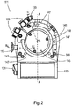
- the turbo-molecular pump 111 shown comprises a pump inlet 115 which is surrounded by an inlet flange 113 and to which a recipient (not shown) can be connected in a manner known per se.
- the gas from the recipient can be sucked out of the recipient via the pump inlet 115 and conveyed through the pump to a pump outlet 117 to which a backing pump, such as a rotary vane pump, can be connected.
- the inlet flange 113 forms according to FIG Fig. 1 the upper end of the housing 119 of the vacuum pump 111.
- the housing 119 comprises a lower part 121 on which an electronics housing 123 is arranged laterally. Electrical and / or electronic components of the vacuum pump 111 are accommodated in the electronics housing 123, for example for operating an electric motor 125 arranged in the vacuum pump. A plurality of connections 127 for accessories are provided on the electronics housing 123.
- a data interface 129 for example in accordance with the RS485 standard, and a power supply connection 131 are arranged on the electronics housing 123.
- a flood inlet 133 in particular in the form of a flood valve, is provided on the housing 119 of the turbo molecular pump 111, via which the vacuum pump 111 can be flooded.
- a sealing gas connection 135, which is also referred to as a purge gas connection via which purge gas to protect the electric motor 125 (see, for example, FIG Fig. 3 ) can be brought into the engine compartment 137, in which the electric motor 125 in the vacuum pump 111 is accommodated, before the gas conveyed by the pump.
- Two coolant connections 139 are also arranged in the lower part 121, one of the coolant connections being provided as an inlet and the other coolant connection being provided as an outlet for coolant which can be passed into the vacuum pump for cooling purposes.
- the lower side 141 of the vacuum pump can serve as a standing surface, so that the vacuum pump 111 can be operated standing on the lower side 141.
- the vacuum pump 111 can, however, also be attached to a recipient via the inlet flange 113 and can thus be operated in a suspended manner, as it were.
- the vacuum pump 111 can be designed in such a way that it can also be put into operation when it is oriented in a different way than in FIG Fig. 1 is shown.
- Embodiments of the vacuum pump can also be implemented in which the underside 141 cannot be arranged facing downwards, but facing to the side or facing upwards.
- a bearing cap 145 is attached to the underside 141.
- Fastening bores 147 are also arranged on the underside 141, via which the pump 111 can be fastened to a support surface, for example.
- a coolant line 148 is shown, in which the coolant introduced and discharged via the coolant connections 139 can circulate.
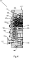
- the vacuum pump comprises several process gas pump stages for conveying the process gas present at the pump inlet 115 to the pump outlet 117.
- a rotor 149 is arranged in the housing 119 and has a rotor shaft 153 rotatable about an axis of rotation 151.
- the turbo-molecular pump 111 comprises several turbo-molecular pump stages connected in series with one another with several radial rotor disks 155 fastened to the rotor shaft 153 and stator disks 157 arranged between the rotor disks 155 and fixed in the housing 119.
- a rotor disk 155 and an adjacent stator disk 157 each form a turbomolecular one Pumping stage.
- the stator disks 157 are held at a desired axial distance from one another by spacer rings 159.
- the vacuum pump also comprises Holweck pump stages which are arranged one inside the other in the radial direction and are connected in series with one another for effective pumping.
- the rotor of the Holweck pump stages comprises a rotor hub 161 arranged on the rotor shaft 153 and two cylinder-jacket-shaped Holweck rotor sleeves 163, 165 which are attached to the rotor hub 161 and carried by the latter, which are oriented coaxially to the axis of rotation 151 and nested in one another in the radial direction.
- two cylinder jacket-shaped Holweck stator sleeves 167, 169 are provided, which are also oriented coaxially to the axis of rotation 151 and, viewed in the radial direction, are nested inside one another.
- the active pumping surfaces of the Holweck pump stages are formed by the jacket surfaces, that is to say by the radial inner and / or outer surfaces, of the Holweck rotor sleeves 163, 165 and the Holweck stator sleeves 167, 169.
- the radial inner surface of the outer Holweck stator sleeve 167 lies opposite the radial outer surface of the outer Holweck rotor sleeve 163 with the formation of a radial Holweck gap 171 and with this forms the first Holweck pumping stage following the turbo molecular pumps.
- the radial inner surface of the outer Holweck rotor sleeve 163 faces the radial outer surface of the inner Holweck stator sleeve 169 with the formation of a radial Holweck gap 173 and with this forms a second Holweck pumping stage.
- the radial inner surface of the inner Holweck stator sleeve 169 lies opposite the radial outer surface of the inner Holweck rotor sleeve 165 with the formation of a radial Holweck gap 175 and with this forms the third Holweck pumping stage.
- a radially running channel can be provided, via which the radially outer Holweck gap 171 is connected to the central Holweck gap 173.
- a radially running channel can be provided at the upper end of the inner Holweck stator sleeve 169, via which the middle Holweck gap 173 is connected to the radially inner Holweck gap 175.
- the nested Holweck pump stages are connected in series with one another.
- the radially inner Holweck rotor sleeve 165 can furthermore be provided with a connection channel 179 to outlet 117.
- the aforementioned pump-active surfaces of the Holweck stator sleeves 163, 165 each have a plurality of Holweck grooves running helically around the axis of rotation 151 in the axial direction, while the opposite lateral surfaces of the Holweck rotor sleeves 163, 165 are smooth and the gas for operating the Drive vacuum pump 111 in the Holweck grooves.
- a roller bearing 181 in the area of the pump outlet 117 and a permanent magnet bearing 183 in the area of the pump inlet 115 are provided for the rotatable mounting of the rotor shaft 153.
- a conical injection molded nut 185 is provided on the rotor shaft 153 with an outer diameter that increases towards the roller bearing 181.
- the injection-molded nut 185 is in sliding contact with at least one stripper of an operating medium store.
- the operating medium reservoir comprises several absorbent discs 187 stacked on top of one another, which are impregnated with an operating medium for the roller bearing 181, for example with a lubricant.
- the operating medium is transferred by capillary action from the operating medium reservoir via the scraper to the rotating injection nut 185 and, as a result of the centrifugal force, is conveyed along the injection nut 185 in the direction of the increasing outer diameter of the injection nut 185 to the roller bearing 181, where it eg fulfills a lubricating function.
- the roller bearing 181 and the operating medium store are enclosed in the vacuum pump by a trough-shaped insert 189 and the bearing cover 145.
- the permanent magnetic bearing 183 comprises a rotor-side bearing half 191 and a stator-side bearing half 193, each of which is a ring stack of several permanent magnetic rings 195, 197 stacked on top of one another in the axial direction.
- the ring magnets 195, 197 are opposite one another with the formation of a radial bearing gap 199, the rotor-side ring magnets 195 being arranged radially on the outside and the stator-side ring magnets 197 being arranged radially on the inside.
- the magnetic field present in the bearing gap 199 causes magnetic repulsive forces between the ring magnets 195, 197, which cause the rotor shaft 153 to be supported radially.
- the rotor-side ring magnets 195 are carried by a carrier section 201 of the rotor shaft 153 which surrounds the ring magnets 195 radially on the outside.
- the stator-side ring magnets 197 are carried by a stator-side support section 203 which extends through the ring magnets 197 and is suspended from radial struts 205 of the housing 119.
- the ring magnets 195 on the rotor side are fixed parallel to the axis of rotation 151 by a cover element 207 coupled to the carrier section 203.
- the stator-side ring magnets 197 are fixed parallel to the axis of rotation 151 in one direction by a fastening ring 209 connected to the carrier section 203 and a fastening ring 211 connected to the carrier section 203.
- a plate spring 213 can also be provided between the fastening ring 211 and the ring magnet 197.
- An emergency or retainer bearing 215 is provided inside the magnetic bearing, which runs empty during normal operation of the vacuum pump 111 without contact and only comes into engagement with an excessive radial deflection of the rotor 149 relative to the stator to create a radial stop for the rotor 149 to form, since a collision of the rotor-side structures with the stator-side structures is prevented.
- the backup bearing 215 is designed as an unlubricated roller bearing and forms a radial gap with the rotor 149 and / or the stator, which has the effect that the backup bearing 215 is disengaged during normal pumping operation.
- the radial deflection at which the safety bearing 215 engages is dimensioned large enough so that the safety bearing 215 is in normal operation of the vacuum pump does not come into engagement, and at the same time small enough that a collision of the rotor-side structures with the stator-side structures is prevented under all circumstances.
- the vacuum pump 111 comprises the electric motor 125 for rotatingly driving the rotor 149.
- the armature of the electric motor 125 is formed by the rotor 149, the rotor shaft 153 of which extends through the motor stator 217.
- a permanent magnet arrangement can be arranged radially on the outside or embedded in the section of the rotor shaft 153 extending through the motor stator 217.
- the motor stator 217 is fixed in the housing within the motor compartment 137 provided for the electric motor 125.
- a sealing gas which is also referred to as a flushing gas and which can be air or nitrogen, for example, can enter the engine compartment 137 via the sealing gas connection 135.
- the electric motor 125 can be protected from process gas, e.g. from corrosive components of the process gas, via the sealing gas.
- the engine compartment 137 can also be evacuated via the pump outlet 117, i.e. in the engine compartment 137 there is at least approximately the vacuum pressure produced by the backing pump connected to the pump outlet 117.
- a so-called labyrinth seal 223, known per se, can also be provided between the rotor hub 161 and a wall 221 delimiting the engine compartment 137, in particular in order to achieve a better sealing of the motor compartment 217 from the Holweck pump stages located radially outside.
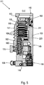
- Fig. 6 shows an embodiment according to the invention of a turbomolecular pump, in which, however, areas are given by way of example in which the respective measuring range of the first and second sensor devices described at the outset lie.
- at least one temperature sensor (not shown) is provided which is arranged in such a way that it can determine the temperature prevailing in an area T1.
- the area T1 is assigned to the insert 189, which receives the ball bearing 181.
- a temperature measurement can take place in an area T1 '.
- the area T1 ′ lies in the lower part 121 and is in direct contact with the insert 189.
- the temperature sensor (s) measure - directly or indirectly - the temperatures prevailing there, which enables direct conclusions to be drawn about the temperature of the roller bearing 181, since the areas T1 and T1 'are in spatial proximity to the bearing 181.
- a normal temperature rise can be concluded, which is determined, for example, by the operating mode of the pump and / or by external factors.
- the operating mode of the pump In the event of an unusual spread in the areas T1, T1 'on the one hand and in the area T2 on the other hand measured data and / or in the case of a temperature rise only in the areas T1, T1 ', this can be due to increasing wear of the bearing 181 or to an impending damage.
- a control device of the pump which records and evaluates the data mentioned, recognizes this and (automatically) initiates countermeasures (e.g. warning signal, stopping the pump, changing the operating mode, adjusting the maintenance interval, etc.).
- the area T2 and the areas T1, T1 ' are thermally coupled in order to enable temperature equalization in normal operation. With proper operation of the pump, a static or quasi-static temperature distribution is established after a certain time at a given load condition.
- the state of the bearing 181 is preferably not monitored until such a state has been reached in order to minimize the risk of false alarms.
- Active cooling for example water cooling
- the cooling increases the spread between the temperature values measured in the areas T1, T1 'on the one hand and T2 on the other hand, which simplifies data analysis.
- a corresponding cooling device is in Fig. 6 only one coolant connection 225 is shown.
- Exemplary spreads are - depending on the cooling - temperature differences of 1 ° C to 5 ° C in a normal storage condition. In the event of impending bearing damage, the spread increases to values of e.g. more than 5 ° C, more than 6 ° C, more than 15 ° C or even larger values.
- the concept of the invention is not limited to turbo molecular pumps, but can also be used with other types of pumps.
Landscapes
- Engineering & Computer Science (AREA)
- Mechanical Engineering (AREA)
- General Engineering & Computer Science (AREA)
- Non-Positive Displacement Air Blowers (AREA)
Description
- Die vorliegende Erfindung betrifft eine Vakuumpumpe, insbesondere Turbomolekularpumpe, mit zumindest einer Pumpstufe, die zumindest einen Rotor umfasst, der mittels zumindest einer Lagereinrichtung drehbar gelagert ist.
- Derartige Vakuumpumpen sind grundsätzlich bekannt und finden eine breite Anwendung, beispielsweise in der Industrie und/oder im wissenschaftlichen Umfeld. Dabei sind nicht nur deren (Betriebs-)Kosten, Leistungsfähigkeit oder Baugröße wesentliche Faktoren, die für den jeweiligen Anwender von Bedeutung sind. Sie müssen auch zuverlässig sein, da ein Ausfall zu Schäden an den Vakuumanlagen führen kann, denen sie zugeordnet sind.
- Die
JP S62 282194 A EP 0 851 127 A2 offenbaren jeweils eine Vakuumpumpe mit den Merkmalen des Oberbegriffs des Anspruchs 1. - Es ist eine Aufgabe der vorliegenden Erfindung, eine Vakuumpumpe der eingangs genannten Bauart zu schaffen, bei der sich anbahnende Schäden noch frühzeitiger erkannt werden können, im Idealfall bevor diese tatsächlich ausfällt.
- Erfindungsgemäß wird eine Vakuumpumpe mit den Merkmalen von Anspruch 1 bereitgestellt. Im Schadensfall oder kurz davor weicht der ermittelte Betriebszustand häufig von einem für den jeweiligen Betriebsmodus charakteristischen normalen Betriebszustand ab. Ein Erkennen einer solchen Abweichung kann dann zur Einleitung entsprechender Gegenmaßnahmen genutzt werden.
- Die Bestimmung der Temperatur der Lagereinrichtung kann direkt an ihr selbst vorgenommen werden. Es ist jedoch auch möglich, die Temperatur in der Nähe der Lagereinrichtung zu bestimmen, insbesondere an Bauteilen, die in einem engen - bevorzugt direktem - Kontakt mit der Lagereinrichtung stehen. Bei einer Bestimmung der Temperatur im nahen Umfeld der Lagereinrichtung kann davon ausgegangen werden, dass der bestimmte Wert im Wesentlichen dem entspricht, der direkt an der Lagereinrichtung bestimmt werden würde.
- Durch eine Bestimmung einer Temperatur der Lagereinrichtung mittels der räumlich nahe bei dieser angeordneten ersten Sensoreinrichtung kann auf ihren Zustand rückgeschlossen werden. Da diese Temperatur allerdings auch in einem fehlerfreien Zustand der Lagereinrichtung bzw. der Vakuumpumpe innerhalb vergleichsweise breiter Grenzen variieren kann, ist die Analyse dieser Temperatur alleine jedoch nicht in jedem Fall aufschlussreich.
- Um eine verlässlichere Analyse des tatsächlichen Zustands der Lagereinrichtung zu ermöglichen, ist daher die zweite Sensoreinrichtung vorgesehen. Sie bestimmt den Zustand der Vakuumpumpe in einem räumlichen Abstand, um zumindest eine weitere Temperatur zu erhalten, die von dem Zustand der Lagereinrichtung nicht oder nur wenig beeinflusst wird.
- Letztlich werden somit Temperaturen verglichen, die einerseits stark und andererseits wenig bis im Wesentlichen gar nicht durch den Zustand der Lagereinrichtung beeinflusst werden. Durch diesen Vergleich können Rückschlüsse auf den Betriebszustand der Lagereinrichtung und/oder dessen zeitliche Änderung gezogen werden. Bei dem Vergleich der Temperaturen Können deren diskrete Werte und/oder deren zeitliche Veränderung berücksichtigt werden.
- Beispielsweise erkennt die Steuereinrichtung auf Basis des Vergleichs, dass die Vakuumpumpe ordnungsgemäß funktioniert, wenn sich die beiden unterschiedlichen Temperaturen innerhalb vorgegebener Grenzen kohärent verändern. Bei einem Hochfahren der Pumpe kann etwa ein Anwachsen beider Temperaturen zu erwarten sein. Sobald sie jedoch auseinanderlaufen, kann dies als Hinweis auf einen sich anbahnenden Lagerschaden aufgefasst werden. Es sind jedoch auch andere Szenarien der zeitlichen Entwicklung der Temperaturen denkbar, die für oder gegen eine Veränderung des Betriebszustands der Lagereinrichtung sprechen.
- In diesem Zusammenhang wird darauf hingewiesen, dass auch mehr als zwei Sensoreinrichtungen vorgesehen sein können, deren Messdaten zur Bestimmung des Betriebszustands der Lagereinrichtung herangezogen werden, um die Zuverlässigkeit der Analyse zu erhöhen und/oder besonderen Anforderungen der Pumpe gerecht zu werden.
- Weitere Ausführungsformen der Erfindung sind in der Beschreibung, den Ansprüchen sowie den beigefügten Zeichnungen angegeben.
- Beispielsweise umfassen die erste und/oder die zweite Sensoreinrichtung einen Temperatursensor. Ein schadhaftes oder verschlissenes Lager weist oftmals Schäden an Komponenten des Lagers auf (z.B. bei einem Kugellager Schäden an den Laufbahnen der Kugeln und/oder am Kugelkäfig), was zu einer erhöhten Lagerreibung führt, die sich wiederum in einer Temperaturerhöhung und/oder in einer Änderungen des Schwingungsverhaltens des Lagers niederschlägt.
- Die Konstruktion der Vakuumpumpe kann dahingehend optimiert sein, einen bestimmten Wert der Wärmeleitfähigkeit zwischen den Temperatursensoren zu erreichen. Bei einem optimalen Wärmewiderstand zwischen den Sensoren wird die Auswertung der ermittelten Temperaturspreizung vereinfacht.
- Die Lagereinrichtung kann zumindest ein Wälzlager, insbesondere zumindest ein Kugellager umfassen. Das Erfindungskonzept ist jedoch auch bei anderen Lagertypen, z.B. bei Gleitlagern, einsetzbar.
- Die erste Sensoreinrichtung kann derart angeordnet sein, dass die Temperatur eines Bauteils der Vakuumpumpe - direkt oder indirekt - bestimmbar ist, das die Lagereinrichtung aufnimmt. Beispielsweise ist ein Temperatursensor vorgesehen, der die Temperatur einer Lagerfassung oder eines der Lagereinrichtung benachbarten Bauteils erfasst. Die Temperatur der Lagereinrichtung kann aber auch direkt an ihr selbst gemessen werden. Bei der Erfassung der Temperatur kann beispielsweise mit einem herkömmlichen Temperatursensor oder mit einem IR-Sensor gearbeitet werden.
- Erfindungsgemäß umfasst die Vakuumpumpe eine aktive Kühleinrichtung, die zumindest zu einer Kühlung eines Bauteils der Vakuumpumpe vorgesehen ist, dessen Betriebsparameter durch die zweite Sensoreinrichtung bestimmbar ist. Dieses Bauteil kann beispielsweise ein Gehäusebauteil sein.
- Gemäß einer weiteren Ausführungsform wird die Lagereinrichtung von einem ersten Bauteil der Vakuumpumpe aufgenommen, das separat von einem zweiten Bauteil der Vakuumpumpe, insbesondere einem Gehäusebauteil (z.B. ein Unterteil) der Vakuumpumpe, ausgebildet ist, dem die zweite Sensoreinrichtung zugeordnet ist. Zwar sind Bauformen denkbar, bei denen die beiden Bauteile durch eine thermische Isolierung voneinander (weitgehend) thermisch entkoppelt sind, bevorzugt stehen das erste und das zweite Bauteil jedoch thermisch leitend miteinander in Verbindung. Es ist aber auch denkbar, dass die erste und die zweite Sensoreinrichtung bzw. deren Messbereich an einem Bauteil angeordnet sind, z.B. an einem Unterteil der Pumpe. Die Sensoreinrichtungen sind auch in diesem Fall räumlich beabstandet, d.h. die erste Sensoreinrichtung ist lagernah angeordnet, während die zweite Sensoreinrichtung lagerfern angeordnet ist.
- Die vorliegende Erfindung betrifft ferner ein Verfahren gemäß Anspruch 6.
- Dem Vergleich kann eine Datenfilterung und/oder -konversion vorangehen oder er kann diese oder ähnliche Verfahren umfassen. Es kann auch vorgesehen sein, dass bei der Datenbearbeitung und/oder -analyse Stabilitätskriterien berücksichtigt werden. Ziel dieser Maßnahmen ist unter anderem, dass nicht relevante (z.B. kurzfristige) Schwankungen in den Daten, die ein falsches Bild vom Zustand des Lagers zeichnen könnten, eliminiert werden.
- D.h. die erste Sensoreinrichtung ist entweder so angeordnet, dass sie die Temperatur der Lagereinrichtung direkt messen kann. Es ist aber auch denkbar, dass die Messung in der näheren Umgebung der Lagereinrichtung durchgeführt wird. Dann kann davon ausgegangen werden, dass der gemessene Wert im Wesentlichen dem entspricht, den man bei einer direkten Messung erhalten würde. Die zweite Sensoreinrichtung soll dahingegen einen Wert eines Betriebszustands liefern, der wenig bis kaum von dem Zustand der Lagereinrichtung beeinflusst wird. Er wird daher in einiger Entfernung von der Lagereinrichtung bestimmt.
- Erfindungsgemäß werden also eine Temperatur der Lagereinrichtung oder eines benachbarten Bauteils, das in direktem oder in direkten Kontakt mit der Lagereinrichtung steht, und eine Temperatur eines Abschnitts eines Gehäuses der Vakuumpumpe als Basis zur Ermittlung des Betriebszustands der Lagereinrichtung herangezogen.
- Gemäß einer weiteren Ausführungsform des Verfahrens umfasst der Vergleich der Temperatur der Lagereinrichtung und der Temperatur der Vakuumpumpe eine Bildung eines Vergleichsparameters. Bei einer Unter- und/oder Überschreitung eines vordefinierten oder erlernten Schwellwerts des Vergleichsparameters wird ein Störfall festgestellt. Für den Vergleichsparameter kann auch ein Parameterraum definiert werden, der einem normalen oder abnormen Zustand entspricht.
- Der Vergleich der Temperatur der Lagereinrichtung und der Temperatur der Vakuumpumpe kann eine Bildung einer Differenz der Temperatur umfassen, wobei bei einer Überschreitung eines vordefinierten oder erlernten Schwellwerts der Differenz ein Störfall festgestellt wird. Der Vergleich kann aber auch eine Quotientenbildung o.ä. unfassen
- Bei Feststellung des Störfalls kann ein Warnsignal ausgegeben werden. Alternativ oder zusätzlich wird automatisch - z.B. durch die Steuereinrichtung - in den Betrieb der Vakuumpumpe eingegriffen, wenn der Störfall eintritt. Beispielsweise wird die Pumpe schonend oder abrupt stillgesetzt oder die Drehzahl der Pumpe wird reduziert, um sie in einen "sicheren" Betriebsmodus zu versetzen. Die Reaktion auf den Eintritt des Störfalls kann in Abhängigkeit von der ermittelten Schwere des Störfalls gewählt werden.
- Um die Zuverlässigkeit der Ermittlung des Betriebszustands zu erhöhen, kann vorgesehen sein, dass der Betriebszustand der Vakuumpumpe erst bestimmt wird, wenn die Temperatur der Vakuumpumpe einen statischen oder quasi-statischen Wert oder Wertebereich erreicht hat. Beispielsweise schwingt sich die Temperaturverteilung in der Vakuumpumpe bei einem Hochfahren der Pumpe erst nach einiger Zeit ein. Die bestimmten Temperaturen der Sensoreinrichtungen liefern währenddessen daher womöglich noch ein Bild, das nicht unbedingt zuverlässige Rückschlüsse auf den tatsächlichen Zustand der Lagereinrichtung zulässt. Es wird mit der entsprechenden Analyse also erst begonnen bzw. die entsprechenden Messdaten werden erst berücksichtigt, wenn die Pumpe einen stabilen Zustand erreicht hat, um die Wahrscheinlichkeit von Fehlalarmen zu minimieren.
- Bei der Bestimmung des Betriebszustands der Vakuumpumpe können weitere Faktoren berücksichtigt werden, insbesondere externe und/oder interne Parameter, bevorzugt eine Laufzeit und/oder ein Alter der Vakuumpumpe, eine externe mechanische Belastung der Vakuumpumpe, eine externe Temperaturbelastung der Vakuumpumpe und/oder ein Betriebsmodus der Vakuumpumpe.
- In vielen Fällen werden die Temperaturen der Lagereinrichtung und/oder der Vakuumpumpe auch von Faktoren beeinflusst, die nicht nur von dem Zustand der Lagereinrichtung und/oder z.B. einer Drehzahl der Pumpe abhängen. Auch ein Alter der Pumpe, eine Laufzeit nach dem letzten Serviceintervall, eine "Historie" der Pumpe (wie lange wurde sie bei welchen Drehzahlen bzw. in welchen Betriebsmodi betrieben), ein Alter des verwendeten Schmiermittel o.ä. beeinflussen die Temperaturen bei einem Betrieb der Pumpe. Gleiches gilt für externe Faktoren, wie etwa eine mechanische Belastung und/oder Schwingungsbelastung der Pumpe und/oder eine Temperaturbelastung der Pumpe.
- So Daten zu diesen Faktoren vorliegen, können sie bei der Ermittlung des Betriebszustands der Lagereinrichtung berücksichtigt werden. Beispielsweise wird der vorstehend beschriebene Schwellwert entsprechend angepasst.
- Die bei der Ermittlung des Betriebszustands der Lagereinrichtung erhaltenen Daten können auch genutzt werden, um einen Zeitpunkt zu bestimmen, zu dem eine Wartung der Pumpe bzw. der Lagereinrichtung vorgenommen werden sollte. Dem Anwender kann auch eine Restlaufzeit des Wartungsintervalls ausgegeben werden. Mit anderen Worten können die genannten Daten zur Optimierung der Wartung genutzt werden, da die Wartungsintervalle bedarfsgerecht und abhängig von der Intensität der Nutzung der Pumpe angepasst werden können.
- Nachfolgend wird die Erfindung beispielhaft anhand vorteilhafter Ausführungsformen unter Bezugnahme auf die beigefügten Figuren beschrieben. Es zeigen, jeweils schematisch:
- Fig. 1
- eine perspektivische Ansicht einer nicht erfindungsgemäßen Turbomolekularpumpe,
- Fig. 2
- eine Ansicht der Unterseite der Turbomolekularpumpe von
Fig. 1 , - Fig. 3
- einen Querschnitt der Turbomolekularpumpe längs der in
Fig. 2 gezeigten Schnittlinie A-A, - Fig. 4
- eine Querschnittsansicht der Turbomolekularpumpe längs der in
Fig. 2 gezeigten Schnittlinie B-B, - Fig. 5
- eine Querschnittsansicht der Turbomolekularpumpe längs der in
Fig. 2 gezeigten Schnittlinie C-C und - Fig. 6
- einen Querschnitt einer erfindungsgemäßen Turbomolekularpumpe.
- Die in
Fig. 1 gezeigte Turbomolekularpumpe 111 umfasst einen von einem Einlassflansch 113 umgebenen Pumpeneinlass 115, an welchen in an sich bekannter Weise ein nicht dargestellter Rezipient angeschlossen werden kann. Das Gas aus dem Rezipienten kann über den Pumpeneinlass 115 aus dem Rezipienten gesaugt und durch die Pumpe hindurch zu einem Pumpenauslass 117 gefördert werden, an den eine Vorvakuumpumpe, wie etwa eine Drehschieberpumpe, angeschlossen sein kann. - Der Einlassflansch 113 bildet bei der Ausrichtung der Vakuumpumpe gemäß
Fig. 1 das obere Ende des Gehäuses 119 der Vakuumpumpe 111. Das Gehäuse 119 umfasst ein Unterteil 121, an welchem seitlich ein Elektronikgehäuse 123 angeordnet ist. In dem Elektronikgehäuse 123 sind elektrische und/oder elektronische Komponenten der Vakuumpumpe 111 untergebracht, z.B. zum Betreiben eines in der Vakuumpumpe angeordneten Elektromotors 125. Am Elektronikgehäuse 123 sind mehrere Anschlüsse 127 für Zubehör vorgesehen. Außerdem sind eine Datenschnittstelle 129, z.B. gemäß dem RS485-Standard, und ein Stromversorgungsanschluss 131 am Elektronikgehäuse 123 angeordnet. - Am Gehäuse 119 der Turbomolekularpumpe 111 ist ein Fluteinlass 133, insbesondere in Form eines Flutventils, vorgesehen, über den die Vakuumpumpe 111 geflutet werden kann. Im Bereich des Unterteils 121 ist ferner noch ein Sperrgasanschluss 135, der auch als Spülgasanschluss bezeichnet wird, angeordnet, über welchen Spülgas zum Schutz des Elektromotors 125 (siehe z.B.
Fig. 3 ) vor dem von der Pumpe geförderten Gas in den Motorraum 137, in welchem der Elektromotor 125 in der Vakuumpumpe 111 untergebracht ist, gebracht werden kann. Im Unterteil 121 sind ferner noch zwei Kühlmittelanschlüsse 139 angeordnet, wobei einer der Kühlmittelanschlüsse als Einlass und der andere Kühlmittelanschluss als Auslass für Kühlmittel vorgesehen ist, das zu Kühlzwecken in die Vakuumpumpe geleitet werden kann. - Die untere Seite 141 der Vakuumpumpe kann als Standfläche dienen, sodass die Vakuumpumpe 111 auf der Unterseite 141 stehend betrieben werden kann. Die Vakuumpumpe 111 kann aber auch über den Einlassflansch 113 an einem Rezipienten befestigt werden und somit gewissermaßen hängend betrieben werden. Außerdem kann die Vakuumpumpe 111 so gestaltet sein, dass sie auch in Betrieb genommen werden kann, wenn sie auf andere Weise ausgerichtet ist als in
Fig. 1 gezeigt ist. Es lassen sich auch Ausführungsformen der Vakuumpumpe realisieren, bei der die Unterseite 141 nicht nach unten, sondern zur Seite gewandt oder nach oben gerichtet angeordnet werden kann. - An der Unterseite 141, die in
Fig. 2 dargestellt ist, sind noch diverse Schrauben 143 angeordnet, mittels denen hier nicht weiter spezifizierte Bauteile der Vakuumpumpe aneinander befestigt sind. Beispielsweise ist ein Lagerdeckel 145 an der Unterseite 141 befestigt. - An der Unterseite 141 sind außerdem Befestigungsbohrungen 147 angeordnet, über welche die Pumpe 111 beispielsweise an einer Auflagefläche befestigt werden kann.
- In den
Figuren 2 bis 5 ist eine Kühlmittelleitung 148 dargestellt, in welcher das über die Kühlmittelanschlüsse 139 ein- und ausgeleitete Kühlmittel zirkulieren kann. - Wie die Schnittdarstellungen der
Figuren 3 bis 5 zeigen, umfasst die Vakuumpumpe mehrere Prozessgaspumpstufen zur Förderung des an dem Pumpeneinlass 115 anstehenden Prozessgases zu dem Pumpenauslass 117. - In dem Gehäuse 119 ist ein Rotor 149 angeordnet, der eine um eine Rotationsachse 151 drehbare Rotorwelle 153 aufweist.
- Die Turbomolekularpumpe 111 umfasst mehrere pumpwirksam miteinander in Serie geschaltete turbomolekulare Pumpstufen mit mehreren an der Rotorwelle 153 befestigten radialen Rotorscheiben 155 und zwischen den Rotorscheiben 155 angeordneten und in dem Gehäuse 119 festgelegten Statorscheiben 157. Dabei bilden eine Rotorscheibe 155 und eine benachbarte Statorscheibe 157 jeweils eine turbomolekulare Pumpstufe. Die Statorscheiben 157 sind durch Abstandsringe 159 in einem gewünschten axialen Abstand zueinander gehalten.
- Die Vakuumpumpe umfasst außerdem in radialer Richtung ineinander angeordnete und pumpwirksam miteinander in Serie geschaltete Holweck-Pumpstufen. Der Rotor der Holweck-Pumpstufen umfasst eine an der Rotorwelle 153 angeordnete Rotornabe 161 und zwei an der Rotornabe 161 befestigte und von dieser getragene zylindermantelförmige Holweck-Rotorhülsen 163, 165, die koaxial zur Rotationsachse 151 orientiert und in radialer Richtung ineinander geschachtelt sind. Ferner sind zwei zylindermantelförmige Holweck-Statorhülsen 167, 169 vorgesehen, die ebenfalls koaxial zu der Rotationsachse 151 orientiert und in radialer Richtung gesehen ineinander geschachtelt sind.
- Die pumpaktiven Oberflächen der Holweck-Pumpstufen sind durch die Mantelflächen, also durch die radialen Innen- und/oder Außenflächen, der Holweck-Rotorhülsen 163, 165 und der Holweck-Statorhülsen 167, 169 gebildet. Die radiale Innenfläche der äußeren Holweck-Statorhülse 167 liegt der radialen Außenfläche der äußeren Holweck-Rotorhülse 163 unter Ausbildung eines radialen Holweck-Spalts 171 gegenüber und bildet mit dieser die der Turbomolekularpumpen nachfolgende erste Holweck-Pumpstufe. Die radiale Innenfläche der äußeren Holweck-Rotorhülse 163 steht der radialen Außenfläche der inneren Holweck-Statorhülse 169 unter Ausbildung eines radialen Holweck-Spalts 173 gegenüber und bildet mit dieser eine zweite Holweck-Pumpstufe. Die radiale Innenfläche der inneren Holweck-Statorhülse 169 liegt der radialen Außenfläche der inneren Holweck-Rotorhülse 165 unter Ausbildung eines radialen Holweck-Spalts 175 gegenüber und bildet mit dieser die dritte Holweck-Pumpstufe.
- Am unteren Ende der Holweck-Rotorhülse 163 kann ein radial verlaufender Kanal vorgesehen sein, über den der radial außenliegende Holweck-Spalt 171 mit dem mittleren Holweck-Spalt 173 verbunden ist. Außerdem kann am oberen Ende der inneren Holweck-Statorhülse 169 ein radial verlaufender Kanal vorgesehen sein, über den der mittlere Holweck-Spalt 173 mit dem radial innenliegenden Holweck-Spalt 175 verbunden ist. Dadurch werden die ineinander geschachtelten Holweck-Pumpstufen in Serie miteinander geschaltet. Am unteren Ende der radial innenliegenden Holweck-Rotorhülse 165 kann ferner ein Verbindungskanal 179 zum Auslass 117 vorgesehen sein.
- Die vorstehend genannten pumpaktiven Oberflächen der Holweck-Statorhülsen 163, 165 weisen jeweils mehrere spiralförmig um die Rotationsachse 151 herum in axialer Richtung verlaufende Holweck-Nuten auf, während die gegenüberliegenden Mantelflächen der Holweck-Rotorhülsen 163, 165 glatt ausgebildet sind und das Gas zum Betrieb der Vakuumpumpe 111 in den Holweck-Nuten vorantreiben.
- Zur drehbaren Lagerung der Rotorwelle 153 sind ein Wälzlager 181 im Bereich des Pumpenauslasses 117 und ein Permanentmagnetlager 183 im Bereich des Pumpeneinlasses 115 vorgesehen.
- Im Bereich des Wälzlagers 181 ist an der Rotorwelle 153 eine konische Spritzmutter 185 mit einem zu dem Wälzlager 181 hin zunehmenden Außendurchmesser vorgesehen. Die Spritzmutter 185 steht mit mindestens einem Abstreifer eines Betriebsmittelspeichers in gleitendem Kontakt. Der Betriebsmittelspeicher umfasst mehrere aufeinander gestapelte saugfähige Scheiben 187, die mit einem Betriebsmittel für das Wälzlager 181, z.B. mit einem Schmiermittel, getränkt sind.
- Im Betrieb der Vakuumpumpe 111 wird das Betriebsmittel durch kapillare Wirkung von dem Betriebsmittelspeicher über den Abstreifer auf die rotierende Spritzmutter 185 übertragen und in Folge der Zentrifugalkraft entlang der Spritzmutter 185 in Richtung des größer werdenden Außendurchmessers der Spritzmutter 185 zu dem Wälzlager 181 hin gefördert, wo es z.B. eine schmierende Funktion erfüllt. Das Wälzlager 181 und der Betriebsmittelspeicher sind durch einen wannenförmigen Einsatz 189 und den Lagerdeckel 145 in der Vakuumpumpe eingefasst.
- Das Permanentmagnetlager 183 umfasst eine rotorseitige Lagerhälfte 191 und eine statorseitige Lagerhälfte 193, welche jeweils einen Ringstapel aus mehreren in axialer Richtung aufeinander gestapelten permanentmagnetischen Ringen 195, 197 umfassen. Die Ringmagnete 195, 197 liegen einander unter Ausbildung eines radialen Lagerspalts 199 gegenüber, wobei die rotorseitigen Ringmagnete 195 radial außen und die statorseitigen Ringmagnete 197 radial innen angeordnet sind. Das in dem Lagerspalt 199 vorhandene magnetische Feld ruft magnetische Abstoßungskräfte zwischen den Ringmagneten 195, 197 hervor, welche eine radiale Lagerung der Rotorwelle 153 bewirken. Die rotorseitigen Ringmagnete 195 sind von einem Trägerabschnitt 201 der Rotorwelle 153 getragen, welcher die Ringmagnete 195 radial außenseitig umgibt. Die statorseitigen Ringmagnete 197 sind von einem statorseitigen Trägerabschnitt 203 getragen, welcher sich durch die Ringmagnete 197 hindurch erstreckt und an radialen Streben 205 des Gehäuses 119 aufgehängt ist. Parallel zu der Rotationsachse 151 sind die rotorseitigen Ringmagnete 195 durch ein mit dem Trägerabschnitt 203 gekoppeltes Deckelelement 207 festgelegt. Die statorseitigen Ringmagnete 197 sind parallel zu der Rotationsachse 151 in der einen Richtung durch einen mit dem Trägerabschnitt 203 verbundenen Befestigungsring 209 sowie einen mit dem Trägerabschnitt 203 verbundenen Befestigungsring 211 festgelegt. Zwischen dem Befestigungsring 211 und den Ringmagneten 197 kann außerdem eine Tellerfeder 213 vorgesehen sein.
- Innerhalb des Magnetlagers ist ein Not- bzw. Fanglager 215 vorgesehen, welches im normalen Betrieb der Vakuumpumpe 111 ohne Berührung leer läuft und erst bei einer übermäßigen radialen Auslenkung des Rotors 149 relativ zu dem Stator in Eingriff gelangt, um einen radialen Anschlag für den Rotor 149 zu bilden, da eine Kollision der rotorseitigen Strukturen mit den statorseitigen Strukturen verhindert wird. Das Fanglager 215 ist als ungeschmiertes Wälzlager ausgebildet und bildet mit dem Rotor 149 und/oder dem Stator einen radialen Spalt, welcher bewirkt, dass das Fanglager 215 im normalen Pumpbetrieb außer Eingriff ist. Die radiale Auslenkung, bei der das Fanglager 215 in Eingriff gelangt, ist groß genug bemessen, sodass das Fanglager 215 im normalen Betrieb der Vakuumpumpe nicht in Eingriff gelangt, und gleichzeitig klein genug, sodass eine Kollision der rotorseitigen Strukturen mit den statorseitigen Strukturen unter allen Umständen verhindert wird.
- Die Vakuumpumpe 111 umfasst den Elektromotor 125 zum drehenden Antreiben des Rotors 149. Der Anker des Elektromotors 125 ist durch den Rotor 149 gebildet, dessen Rotorwelle 153 sich durch den Motorstator 217 hindurch erstreckt. Auf den sich durch den Motorstator 217 hindurch erstreckenden Abschnitt der Rotorwelle 153 kann radial außenseitig oder eingebettet eine Permanentmagnetanordnung angeordnet sein. Zwischen dem Motorstator 217 und dem sich durch den Motorstator 217 hindurch erstreckenden Abschnitt des Rotors 149 ist ein Zwischenraum 219 angeordnet, welcher einen radialen Motorspalt umfasst, über den sich der Motorstator 217 und die Permanentmagnetanordnung zur Übertragung des Antriebsmoments magnetisch beeinflussen können.
- Der Motorstator 217 ist in dem Gehäuse innerhalb des für den Elektromotor 125 vorgesehenen Motorraums 137 festgelegt. Über den Sperrgasanschluss 135 kann ein Sperrgas, das auch als Spülgas bezeichnet wird, und bei dem es sich beispielsweise um Luft oder um Stickstoff handeln kann, in den Motorraum 137 gelangen. Über das Sperrgas kann der Elektromotor 125 vor Prozessgas, z.B. vor korrosiv wirkenden Anteilen des Prozessgases, geschützt werden. Der Motorraum 137 kann auch über den Pumpenauslass 117 evakuiert werden, d.h. im Motorraum 137 herrscht zumindest annäherungsweise der von der am Pumpenauslass 117 angeschlossenen Vorvakuumpumpe bewirkte Vakuumdruck.
- Zwischen der Rotornabe 161 und einer den Motorraum 137 begrenzenden Wandung 221 kann außerdem eine sog. und an sich bekannte Labyrinthdichtung 223 vorgesehen sein, insbesondere um eine bessere Abdichtung des Motorraums 217 gegenüber den radial außerhalb liegenden Holweck-Pumpstufen zu erreichen.
-
Fig. 6 zeigt eine erfindungsgemäße Ausführungsform einer Turbomolekularpumpe, bei der jedoch beispielhaft Bereiche angegeben sind, in denen der jeweilige Messbereich der eingangs beschriebenen ersten und die zweiten Sensoreinrichtung liegt. Im vorliegenden Beispiel ist einerseits zumindest ein Temperatursensor (nicht gezeigt) vorgesehen, der derart angeordnet ist, dass er die in einem Bereich T1 herrschende Temperatur bestimmen kann. Der Bereich T1 ist dem Einsatz 189 zugeordnet, der das Kugellager 181 aufnimmt. Alternativ oder zusätzlich kann eine Temperaturmessung in einem Bereich T1' erfolgen. Der Bereich T1' liegt in dem Unterteil 121 und steht in direktem Kontakt mit dem Einsatz 189. - Der oder die Temperatursensoren messen - direkt oder indirekt - also die dort herrschenden Temperaturen, was direkte Rückschlüsse auf die Temperatur des Wälzlagers 181 ermöglicht, da sich die Bereiche T1 und T1' in räumlicher Nähe zu dem Lager 181 befinden. Auch eine Temperaturmessung direkt an einer Komponente des Lagers 181, z.B. an dessen Außenring, ist denkbar.
- Bei einem Lagerschaden und/oder einem Verschleiß des Lagers 181 erhitzt sich dieses stärker als normal. Um trennen zu können, ob eine Temperaturerhöhung des Lagers 181 - diese führt dann auch zu einer Temperaturerhöhung in den Bereichen T1, T1' - nicht ihre Ursache in einer höheren Belastung der Pumpe an sich hat, werden die in den Bereichen T1, T1' ermittelten Temperaturdaten mit Daten verglichen, die in zumindest einem Bereich gemessen werden, die nicht oder nur kaum von einer Temperaturerhöhung des Lagers 181 beeinflusst wird. Im vorliegenden Beispiel ist der von dem Lager 181 räumlich beabstandete Bereich T2 des Unterteils 121.
- Steigt dort in einer bestimmten Situation ebenfalls die Temperatur, so kann auf einen normalen Temperaturanstieg geschlossen werden, der z.B. vom Betriebsmodus der Pumpe und/oder von externen Faktoren bestimmt wird. Bei einer ungewöhnlichen Spreizung der in den Bereichen T1, T1' einerseits und im Bereich T2 andererseits gemessenen Daten und/oder bei einem Temperaturanstieg nur in den Bereichen T1, T1' kann dies auf einen zunehmenden Verschleiß des Lagers 181 oder einen anstehenden Schaden zurückzuführen sein. Eine Steuereinrichtung der Pumpe, die die genannten Daten erfasst und auswertet, erkennt dies und leitet (automatisch) Gegenmaßnahmen ein (z.B. Warnsignal, Stillsetzung der Pumpe, Änderung des Betriebsmodus, Anpassung des Wartungsintervalls o.ä.). Bei der Auswertung der genannten Daten können - wie eingangs erläutert - auch externe Faktoren und/oder die "Geschichte" der Pumpe sowie der Betriebsmodus, mit dem die Pumpe jeweils aktuell betrieben wird, berücksichtigt werden, um die Lagerüberwachung zu optimieren. Die für die Lagerüberwachung verwendeten Schwellenwerte und/oder Vergleichsparameter können in der Steuereinrichtung hinterlegt sein und/oder erlernt werden. Es kann vorgesehen sein, dass die im Rahmen der Lagerüberwachung ermittelten Daten bzw. die daraus hervorgegangenen Analysen abgespeichert und/oder an externe Datenspeicher (z.B. einen Server des Pumpenherstellers) übermittelt werden, um Wartungsintervalle anpassen und/oder Fehler frühzeitig erkennen und deren Ursachen besser analysieren zu können.
- Der Bereich T2 und die Bereiche T1, T1' sind thermisch gekoppelt, um in einem normalen Betrieb einen Temperaturausgleich zu ermöglichen. Bei einem ordnungsgemäßen Betrieb der Pumpe stellt sich nämlich bei einem gegebenen Lastzustand nach einer gewissen Zeit eine statische oder quasi-statische Temperaturverteilung ein. Bevorzugt wird der Zustand des Lagers 181 erst überwacht, wenn ein solcher Zustand erreicht wurde, um die Gefahr von Fehlalarmen zu minimieren.
- Es ist eine aktive Kühlung, z.B. eine Wasserkühlung, vorgesehen, die vor allem den Bereich T2 beeinflusst. Die Kühlung vergrößert die Spreizung zwischen den in den Bereichen T1, T1' einerseits und T2 andererseits gemessenen Temperaturwerten, was die Datenanalyse vereinfacht. Von einer entsprechenden Kühleinrichtung ist in
Fig. 6 nur ein Kühlmittelanschluss 225 gezeigt. - Beispielhafte Spreizungen sind - abhängig von der Kühlung - Temperaturdifferenzen von 1°C bis 5°C bei einem normalen Lagerzustand. Bei einem sich anbahnenden Lagerschaden steigt die Spreizung auf Werte von z.B. mehr als 5°C, mehr als 6°C, mehr als 15°C oder sogar noch größere Werte.
- Vorstehend wurde das Konzept der vorliegenden Erfindung anhand von Temperatursensoren erläutert. Deren lagernahen und lagerfernen Messbereiche T1, T1' bzw. T2 sind rein beispielhaft angegeben. Es versteht sich, dass die Temperaturen auch an mehreren Stellen gemessen werden können, um eine noch bessere Datenbasis zu erhalten.
- Das Erfindungskonzept ist nicht auf Turbomolekularpumpen beschränkt, sondern kann auch bei anderen Pumpentypen zum Einsatz gelangen.
-
- 111
- Turbomolekularpumpe
- 113
- Einlassflansch
- 115
- Pumpeneinlass
- 117
- Pumpenauslass
- 119
- Gehäuse
- 121
- Unterteil
- 123
- Elektronikgehäuse
- 125
- Elektromotor
- 127
- Zubehöranschluss
- 129
- Datenschnittstelle
- 131
- Stromversorgungsanschluss
- 133
- Fluteinlass
- 135
- Sperrgasanschluss
- 137
- Motorraum
- 139
- Kühlmittelanschluss
- 141
- Unterseite
- 143
- Schraube
- 145
- Lagerdeckel
- 147
- Befestigungsbohrung
- 148
- Kühlmittelleitung
- 149
- Rotor
- 151
- Rotationsachse
- 153
- Rotorwelle
- 155
- Rotorscheibe
- 157
- Statorscheibe
- 159
- Abstandsring
- 161
- Rotornabe
- 163
- Holweck-Rotorhülse
- 165
- Holweck-Rotorhülse
- 167
- Holweck-Statorhülse
- 169
- Holweck-Statorhülse
- 171
- Holweck-Spalt
- 173
- Holweck-Spalt
- 175
- Holweck-Spalt
- 179
- Verbindungskanal
- 181
- Wälzlager
- 183
- Permanentmagnetlager
- 185
- Spritzmutter
- 187
- Scheibe
- 189
- Einsatz
- 191
- rotorseitige Lagerhälfte
- 193
- statorseitige Lagerhälfte
- 195
- Ringmagnet
- 197
- Ringmagnet
- 199
- Lagerspalt
- 201
- Trägerabschnitt
- 203
- Trägerabschnitt
- 205
- radiale Strebe
- 207
- Deckelelement
- 209
- Stützring
- 211
- Befestigungsring
- 213
- Tellerfeder
- 215
- Not- bzw. Fanglager
- 217
- Motorstator
- 219
- Zwischenraum
- 221
- Wandung
- 223
- Labyrinthdichtung
- 225
- Kühlmittelanschluss
- T1, T1'
- lagernaher Messbereich
- T2
- lagerferner Messbereich
Claims (11)
- Vakuumpumpe, insbesondere Turbomolekularpumpe, mit zumindest einer Pumpstufe, die zumindest einen Rotor umfasst, der mittels zumindest einer Lagereinrichtung drehbar gelagert ist, mit einer ersten Sensoreinrichtung, die benachbart zu der Lagereinrichtung angeordnet ist und mit der eine Temperatur der Lagereinrichtung bestimmbar ist, und mit einer zweiten Sensoreinrichtung, die beabstandet von der Lagereinrichtung angeordnet ist und mit der eine Temperatur der Vakuumpumpe, insbesondere eine Temperatur eines Gehäuses der Vakuumpumpe, bestimmbar ist, wobei eine Steuereinrichtung vorgesehen ist, die dazu ausgebildet und eingerichtet ist, die Temperatur der Lagereinrichtung und die Temperatur der Vakuumpumpe miteinander zu vergleichen und auf Basis des Vergleichs einen Betriebszustand der Lagereinrichtung zu ermitteln,
dadurch gekennzeichnet, dass
die Vakuumpumpe eine aktive Kühleinrichtung umfasst, die zumindest zu einer Kühlung eines Bauteils der Vakuumpumpe vorgesehen ist, dessen Temperatur durch die zweite Sensoreinrichtung bestimmbar ist. - Vakuumpumpe nach Anspruch 1 ,
dadurch gekennzeichnet, dass
die erste und die zweite Sensoreinrichtung einen Temperatursensor umfassen. - Vakuumpumpe nach zumindest einem der vorstehenden Ansprüche,
dadurch gekennzeichnet, dass
die Lagereinrichtung zumindest ein Wälzlager, insbesondere zumindest ein Kugellager umfasst. - Vakuumpumpe nach zumindest einem der vorstehenden Ansprüche,
dadurch gekennzeichnet, dass
die erste Sensoreinrichtung derart angeordnet ist, dass die Temperatur eines Bauteils der Vakuumpumpe - direkt oder indirekt - bestimmbar ist, das die Lagereinrichtung aufnimmt. - Vakuumpumpe nach Anspruch 4,
dadurch gekennzeichnet, dass
die Lagereinrichtung von einem ersten Bauteil der Vakuumpumpe aufgenommen wird, das separat von einem zweiten Bauteil der Vakuumpumpe, insbesondere einem Gehäusebauteil der Vakuumpumpe, ausgebildet ist, dem die zweite Sensoreinrichtung zugeordnet ist, insbesondere wobei das erste und das zweite Bauteil thermisch leitend miteinander gekoppelt sind. - Verfahren zum Betrieb einer Vakuumpumpe gemäß zumindest einem der Ansprüche 1 bis 5, wobei die Temperatur der Lagereinrichtung und die Temperatur der Vakuumpumpe miteinander verglichen werden und auf Basis des Vergleichs ein Betriebszustand der Lagereinrichtung ermittelt wird.
- Verfahren nach Anspruch 6,
dadurch gekennzeichnet, dass
der Vergleich der Temperatur
der Lagereinrichtung und der Temperatur der Vakuumpumpe eine Bildung eines Vergleichsparameters umfasst und dass bei einer Unter- und/oder Überschreitung eines Schwellwerts des Vergleichsparameters ein Störfall festgestellt wird. - Verfahren nach Anspruch 7,
dadurch gekennzeichnet, dass
der Vergleich der Temperatur
der Lagereinrichtung und der Temperatur der Vakuumpumpe eine Bildung einer Differenz der Temperatur umfasst und dass bei einer Überschreitung eines Schwellwerts der Differenz ein Störfall festgestellt wird. - Verfahren nach Anspruch 7 oder 8,
dadurch gekennzeichnet, dass
bei Feststellung des Störfalls ein Warnsignal ausgegeben wird und/oder automatisch in den Betrieb der Vakuumpumpe eingegriffen wird. - Verfahren nach zumindest einem der Ansprüche 6 bis 9, dadurch gekennzeichnet, dass
der Betriebszustand der Vakuumpumpe erst bestimmt wird, wenn die Temperatur der Vakuumpumpe einen statischen oder quasi-statischen Wert oder Wertebereich erreicht hat. - Verfahren nach zumindest einem der Ansprüche 6 bis 10,
dadurch gekennzeichnet, dass
bei der Bestimmung des Betriebszustands der Vakuumpumpe weitere Faktoren berücksichtigt werden, insbesondere externe und/oder interne Parameter, bevorzugt eine Laufzeit und/oder ein Alter der Vakuumpumpe, eine externe mechanische Belastung der Vakuumpumpe, eine externe Temperaturbelastung der Vakuumpumpe und/oder ein Betriebsmodus der Vakuumpumpe.
Priority Applications (2)
| Application Number | Priority Date | Filing Date | Title |
|---|---|---|---|
| EP19159776.4A EP3557072B1 (de) | 2019-02-27 | 2019-02-27 | Überwachung der lagereinrichtung einer vakuumpumpe |
| JP2020028168A JP7239510B2 (ja) | 2019-02-27 | 2020-02-21 | 真空ポンプ |
Applications Claiming Priority (1)
| Application Number | Priority Date | Filing Date | Title |
|---|---|---|---|
| EP19159776.4A EP3557072B1 (de) | 2019-02-27 | 2019-02-27 | Überwachung der lagereinrichtung einer vakuumpumpe |
Publications (2)
| Publication Number | Publication Date |
|---|---|
| EP3557072A1 EP3557072A1 (de) | 2019-10-23 |
| EP3557072B1 true EP3557072B1 (de) | 2021-02-24 |
Family
ID=65628702
Family Applications (1)
| Application Number | Title | Priority Date | Filing Date |
|---|---|---|---|
| EP19159776.4A Active EP3557072B1 (de) | 2019-02-27 | 2019-02-27 | Überwachung der lagereinrichtung einer vakuumpumpe |
Country Status (2)
| Country | Link |
|---|---|
| EP (1) | EP3557072B1 (de) |
| JP (1) | JP7239510B2 (de) |
Families Citing this family (2)
| Publication number | Priority date | Publication date | Assignee | Title |
|---|---|---|---|---|
| EP4174321B1 (de) * | 2021-10-29 | 2024-01-17 | Pfeiffer Vacuum Technology AG | Vakuumpumpe |
| GB2619964B (en) * | 2022-06-24 | 2024-12-25 | Edwards Ltd | Method for detection of a bearing condition of a vacuum pump |
Family Cites Families (7)
| Publication number | Priority date | Publication date | Assignee | Title |
|---|---|---|---|---|
| JPS62282194A (ja) * | 1986-05-30 | 1987-12-08 | Mitsubishi Electric Corp | タ−ボ分子ポンプ装置 |
| IT1289811B1 (it) * | 1996-12-27 | 1998-10-16 | Varian Spa | Metodo ed apparato di diagnosi per pompa da vuoto. |
| JPH10306790A (ja) * | 1997-05-01 | 1998-11-17 | Daikin Ind Ltd | 分子ポンプ |
| DE102006034478A1 (de) | 2006-07-26 | 2008-01-31 | Oerlikon Leybold Vacuum Gmbh | Verfahren zur Ermittlung einer Aussage über einen Zustand einer Turbomolekularpumpe sowie eine Turbomolekularpumpe |
| KR101629979B1 (ko) * | 2008-07-14 | 2016-06-13 | 에드워즈 가부시키가이샤 | 진공 펌프 |
| JP6287475B2 (ja) | 2014-03-28 | 2018-03-07 | 株式会社島津製作所 | 真空ポンプ |
| JP2018159340A (ja) * | 2017-03-23 | 2018-10-11 | 株式会社島津製作所 | 真空ポンプの制御装置、およびポンプ装置 |
-
2019
- 2019-02-27 EP EP19159776.4A patent/EP3557072B1/de active Active
-
2020
- 2020-02-21 JP JP2020028168A patent/JP7239510B2/ja active Active
Also Published As
| Publication number | Publication date |
|---|---|
| JP2020139504A (ja) | 2020-09-03 |
| JP7239510B2 (ja) | 2023-03-14 |
| EP3557072A1 (de) | 2019-10-23 |
Similar Documents
| Publication | Publication Date | Title |
|---|---|---|
| EP3653885B1 (de) | Verfahren zum ermitteln einer zustandsinformation in einem vakuumgerät | |
| EP3808988B1 (de) | Vakuumpumpe und verfahren zum überwachen einer vakuumpumpe | |
| EP3832141B1 (de) | Verfahren zum betreiben einer vakuumpumpe | |
| EP3557072B1 (de) | Überwachung der lagereinrichtung einer vakuumpumpe | |
| EP3557073A1 (de) | Vakuumpumpe | |
| EP3657021A1 (de) | Vakuumpumpe | |
| EP3438460B1 (de) | Vakuumpumpe | |
| EP3112687B1 (de) | Feststellung der strömung eines hilfsgases, das in eine vakuumpumpe gespeist wird | |
| EP3660317B1 (de) | Vakuumgerät | |
| EP4144994B1 (de) | Vorrichtung und verfahren zum bewerten eines magnetlagers | |
| EP3135932B1 (de) | Vakuumpumpe und permanentmagnetlager | |
| EP3636933B1 (de) | Verfahren zum ermitteln einer temperatur mittels eines infrarot-sensors | |
| EP4137699B1 (de) | Vakuumgerät und verfahren zum betreiben eines solchen | |
| EP3683449A1 (de) | Magnetlager und vakuumgerät | |
| EP3536965B1 (de) | Vakuumpumpe, wobei der träger eines wälzlagers eine veränderbare steifigkeit und/oder dämpfungswirkung hat | |
| EP3633204B1 (de) | Vakuumpumpe | |
| EP2927501B1 (de) | Verfahren und System zur Ermittlung und Bewertung der Einbauorientierung einer Einrichtung | |
| EP3611383B1 (de) | Drehzahlregelung eines rotors einer vakuumpumpe | |
| EP3628873B1 (de) | Rotorlagerung | |
| EP3926174B1 (de) | Vakuumpumpe | |
| EP3536966B1 (de) | Vakuumgerät | |
| EP3736447A1 (de) | Vakuumpumpe und verfahren zum überwachen einer vakuumpumpe | |
| EP3557071B1 (de) | Vakuumpumpe und verfahren zum betreiben derselben | |
| EP4174321B1 (de) | Vakuumpumpe | |
| EP4269805A1 (de) | Vakuumpumpe |
Legal Events
| Date | Code | Title | Description |
|---|---|---|---|
| PUAI | Public reference made under article 153(3) epc to a published international application that has entered the european phase |
Free format text: ORIGINAL CODE: 0009012 |
|
| STAA | Information on the status of an ep patent application or granted ep patent |
Free format text: STATUS: THE APPLICATION HAS BEEN PUBLISHED |
|
| AK | Designated contracting states |
Kind code of ref document: A1 Designated state(s): AL AT BE BG CH CY CZ DE DK EE ES FI FR GB GR HR HU IE IS IT LI LT LU LV MC MK MT NL NO PL PT RO RS SE SI SK SM TR |
|
| AX | Request for extension of the european patent |
Extension state: BA ME |
|
| STAA | Information on the status of an ep patent application or granted ep patent |
Free format text: STATUS: REQUEST FOR EXAMINATION WAS MADE |
|
| 17P | Request for examination filed |
Effective date: 20200423 |
|
| RBV | Designated contracting states (corrected) |
Designated state(s): AL AT BE BG CH CY CZ DE DK EE ES FI FR GB GR HR HU IE IS IT LI LT LU LV MC MK MT NL NO PL PT RO RS SE SI SK SM TR |
|
| GRAP | Despatch of communication of intention to grant a patent |
Free format text: ORIGINAL CODE: EPIDOSNIGR1 |
|
| STAA | Information on the status of an ep patent application or granted ep patent |
Free format text: STATUS: GRANT OF PATENT IS INTENDED |
|
| INTG | Intention to grant announced |
Effective date: 20200918 |
|
| RIN1 | Information on inventor provided before grant (corrected) |
Inventor name: STOLL, TOBIAS Inventor name: SCHNARR,JOHANNES Inventor name: BOETTCHER, JOCHEN Inventor name: SCHWEIGHOEFER, MICHAEL |
|
| GRAS | Grant fee paid |
Free format text: ORIGINAL CODE: EPIDOSNIGR3 |
|
| GRAA | (expected) grant |
Free format text: ORIGINAL CODE: 0009210 |
|
| STAA | Information on the status of an ep patent application or granted ep patent |
Free format text: STATUS: THE PATENT HAS BEEN GRANTED |
|
| AK | Designated contracting states |
Kind code of ref document: B1 Designated state(s): AL AT BE BG CH CY CZ DE DK EE ES FI FR GB GR HR HU IE IS IT LI LT LU LV MC MK MT NL NO PL PT RO RS SE SI SK SM TR |
|
| REG | Reference to a national code |
Ref country code: CH Ref legal event code: EP |
|
| REG | Reference to a national code |
Ref country code: DE Ref legal event code: R096 Ref document number: 502019000833 Country of ref document: DE |
|
| REG | Reference to a national code |
Ref country code: AT Ref legal event code: REF Ref document number: 1364776 Country of ref document: AT Kind code of ref document: T Effective date: 20210315 |
|
| REG | Reference to a national code |
Ref country code: IE Ref legal event code: FG4D Free format text: LANGUAGE OF EP DOCUMENT: GERMAN |
|
| REG | Reference to a national code |
Ref country code: LT Ref legal event code: MG9D |
|
| REG | Reference to a national code |
Ref country code: NL Ref legal event code: MP Effective date: 20210224 |
|
| PG25 | Lapsed in a contracting state [announced via postgrant information from national office to epo] |
Ref country code: BG Free format text: LAPSE BECAUSE OF FAILURE TO SUBMIT A TRANSLATION OF THE DESCRIPTION OR TO PAY THE FEE WITHIN THE PRESCRIBED TIME-LIMIT Effective date: 20210524 Ref country code: HR Free format text: LAPSE BECAUSE OF FAILURE TO SUBMIT A TRANSLATION OF THE DESCRIPTION OR TO PAY THE FEE WITHIN THE PRESCRIBED TIME-LIMIT Effective date: 20210224 Ref country code: GR Free format text: LAPSE BECAUSE OF FAILURE TO SUBMIT A TRANSLATION OF THE DESCRIPTION OR TO PAY THE FEE WITHIN THE PRESCRIBED TIME-LIMIT Effective date: 20210525 Ref country code: FI Free format text: LAPSE BECAUSE OF FAILURE TO SUBMIT A TRANSLATION OF THE DESCRIPTION OR TO PAY THE FEE WITHIN THE PRESCRIBED TIME-LIMIT Effective date: 20210224 Ref country code: NO Free format text: LAPSE BECAUSE OF FAILURE TO SUBMIT A TRANSLATION OF THE DESCRIPTION OR TO PAY THE FEE WITHIN THE PRESCRIBED TIME-LIMIT Effective date: 20210524 Ref country code: PT Free format text: LAPSE BECAUSE OF FAILURE TO SUBMIT A TRANSLATION OF THE DESCRIPTION OR TO PAY THE FEE WITHIN THE PRESCRIBED TIME-LIMIT Effective date: 20210624 Ref country code: LT Free format text: LAPSE BECAUSE OF FAILURE TO SUBMIT A TRANSLATION OF THE DESCRIPTION OR TO PAY THE FEE WITHIN THE PRESCRIBED TIME-LIMIT Effective date: 20210224 |
|
| PG25 | Lapsed in a contracting state [announced via postgrant information from national office to epo] |
Ref country code: NL Free format text: LAPSE BECAUSE OF FAILURE TO SUBMIT A TRANSLATION OF THE DESCRIPTION OR TO PAY THE FEE WITHIN THE PRESCRIBED TIME-LIMIT Effective date: 20210224 Ref country code: PL Free format text: LAPSE BECAUSE OF FAILURE TO SUBMIT A TRANSLATION OF THE DESCRIPTION OR TO PAY THE FEE WITHIN THE PRESCRIBED TIME-LIMIT Effective date: 20210224 Ref country code: LV Free format text: LAPSE BECAUSE OF FAILURE TO SUBMIT A TRANSLATION OF THE DESCRIPTION OR TO PAY THE FEE WITHIN THE PRESCRIBED TIME-LIMIT Effective date: 20210224 Ref country code: RS Free format text: LAPSE BECAUSE OF FAILURE TO SUBMIT A TRANSLATION OF THE DESCRIPTION OR TO PAY THE FEE WITHIN THE PRESCRIBED TIME-LIMIT Effective date: 20210224 Ref country code: SE Free format text: LAPSE BECAUSE OF FAILURE TO SUBMIT A TRANSLATION OF THE DESCRIPTION OR TO PAY THE FEE WITHIN THE PRESCRIBED TIME-LIMIT Effective date: 20210224 |
|
| PG25 | Lapsed in a contracting state [announced via postgrant information from national office to epo] |
Ref country code: IS Free format text: LAPSE BECAUSE OF FAILURE TO SUBMIT A TRANSLATION OF THE DESCRIPTION OR TO PAY THE FEE WITHIN THE PRESCRIBED TIME-LIMIT Effective date: 20210624 |
|
| REG | Reference to a national code |
Ref country code: BE Ref legal event code: MM Effective date: 20210228 |
|
| PG25 | Lapsed in a contracting state [announced via postgrant information from national office to epo] |
Ref country code: EE Free format text: LAPSE BECAUSE OF FAILURE TO SUBMIT A TRANSLATION OF THE DESCRIPTION OR TO PAY THE FEE WITHIN THE PRESCRIBED TIME-LIMIT Effective date: 20210224 Ref country code: LU Free format text: LAPSE BECAUSE OF NON-PAYMENT OF DUE FEES Effective date: 20210227 Ref country code: SM Free format text: LAPSE BECAUSE OF FAILURE TO SUBMIT A TRANSLATION OF THE DESCRIPTION OR TO PAY THE FEE WITHIN THE PRESCRIBED TIME-LIMIT Effective date: 20210224 |
|
| REG | Reference to a national code |
Ref country code: DE Ref legal event code: R097 Ref document number: 502019000833 Country of ref document: DE |
|
| PG25 | Lapsed in a contracting state [announced via postgrant information from national office to epo] |
Ref country code: MC Free format text: LAPSE BECAUSE OF FAILURE TO SUBMIT A TRANSLATION OF THE DESCRIPTION OR TO PAY THE FEE WITHIN THE PRESCRIBED TIME-LIMIT Effective date: 20210224 Ref country code: DK Free format text: LAPSE BECAUSE OF FAILURE TO SUBMIT A TRANSLATION OF THE DESCRIPTION OR TO PAY THE FEE WITHIN THE PRESCRIBED TIME-LIMIT Effective date: 20210224 Ref country code: RO Free format text: LAPSE BECAUSE OF FAILURE TO SUBMIT A TRANSLATION OF THE DESCRIPTION OR TO PAY THE FEE WITHIN THE PRESCRIBED TIME-LIMIT Effective date: 20210224 Ref country code: SK Free format text: LAPSE BECAUSE OF FAILURE TO SUBMIT A TRANSLATION OF THE DESCRIPTION OR TO PAY THE FEE WITHIN THE PRESCRIBED TIME-LIMIT Effective date: 20210224 |
|
| PLBE | No opposition filed within time limit |
Free format text: ORIGINAL CODE: 0009261 |
|
| STAA | Information on the status of an ep patent application or granted ep patent |
Free format text: STATUS: NO OPPOSITION FILED WITHIN TIME LIMIT |
|
| PG25 | Lapsed in a contracting state [announced via postgrant information from national office to epo] |
Ref country code: ES Free format text: LAPSE BECAUSE OF FAILURE TO SUBMIT A TRANSLATION OF THE DESCRIPTION OR TO PAY THE FEE WITHIN THE PRESCRIBED TIME-LIMIT Effective date: 20210224 Ref country code: FR Free format text: LAPSE BECAUSE OF NON-PAYMENT OF DUE FEES Effective date: 20210424 Ref country code: AL Free format text: LAPSE BECAUSE OF FAILURE TO SUBMIT A TRANSLATION OF THE DESCRIPTION OR TO PAY THE FEE WITHIN THE PRESCRIBED TIME-LIMIT Effective date: 20210224 Ref country code: IE Free format text: LAPSE BECAUSE OF NON-PAYMENT OF DUE FEES Effective date: 20210227 |
|
| 26N | No opposition filed |
Effective date: 20211125 |
|
| PG25 | Lapsed in a contracting state [announced via postgrant information from national office to epo] |
Ref country code: SI Free format text: LAPSE BECAUSE OF FAILURE TO SUBMIT A TRANSLATION OF THE DESCRIPTION OR TO PAY THE FEE WITHIN THE PRESCRIBED TIME-LIMIT Effective date: 20210224 |
|
| PG25 | Lapsed in a contracting state [announced via postgrant information from national office to epo] |
Ref country code: IS Free format text: LAPSE BECAUSE OF FAILURE TO SUBMIT A TRANSLATION OF THE DESCRIPTION OR TO PAY THE FEE WITHIN THE PRESCRIBED TIME-LIMIT Effective date: 20210624 |
|
| PG25 | Lapsed in a contracting state [announced via postgrant information from national office to epo] |
Ref country code: BE Free format text: LAPSE BECAUSE OF NON-PAYMENT OF DUE FEES Effective date: 20210228 |
|
| REG | Reference to a national code |
Ref country code: CH Ref legal event code: PL |
|
| PG25 | Lapsed in a contracting state [announced via postgrant information from national office to epo] |
Ref country code: LI Free format text: LAPSE BECAUSE OF NON-PAYMENT OF DUE FEES Effective date: 20220228 Ref country code: CH Free format text: LAPSE BECAUSE OF NON-PAYMENT OF DUE FEES Effective date: 20220228 |
|
| PG25 | Lapsed in a contracting state [announced via postgrant information from national office to epo] |
Ref country code: CY Free format text: LAPSE BECAUSE OF FAILURE TO SUBMIT A TRANSLATION OF THE DESCRIPTION OR TO PAY THE FEE WITHIN THE PRESCRIBED TIME-LIMIT Effective date: 20210224 |
|
| PG25 | Lapsed in a contracting state [announced via postgrant information from national office to epo] |
Ref country code: HU Free format text: LAPSE BECAUSE OF FAILURE TO SUBMIT A TRANSLATION OF THE DESCRIPTION OR TO PAY THE FEE WITHIN THE PRESCRIBED TIME-LIMIT; INVALID AB INITIO Effective date: 20190227 |
|
| PG25 | Lapsed in a contracting state [announced via postgrant information from national office to epo] |
Ref country code: MK Free format text: LAPSE BECAUSE OF FAILURE TO SUBMIT A TRANSLATION OF THE DESCRIPTION OR TO PAY THE FEE WITHIN THE PRESCRIBED TIME-LIMIT Effective date: 20210224 |
|
| PG25 | Lapsed in a contracting state [announced via postgrant information from national office to epo] |
Ref country code: TR Free format text: LAPSE BECAUSE OF FAILURE TO SUBMIT A TRANSLATION OF THE DESCRIPTION OR TO PAY THE FEE WITHIN THE PRESCRIBED TIME-LIMIT Effective date: 20210224 |
|
| PG25 | Lapsed in a contracting state [announced via postgrant information from national office to epo] |
Ref country code: MT Free format text: LAPSE BECAUSE OF FAILURE TO SUBMIT A TRANSLATION OF THE DESCRIPTION OR TO PAY THE FEE WITHIN THE PRESCRIBED TIME-LIMIT Effective date: 20210224 |
|
| REG | Reference to a national code |
Ref country code: AT Ref legal event code: MM01 Ref document number: 1364776 Country of ref document: AT Kind code of ref document: T Effective date: 20240227 |
|
| PG25 | Lapsed in a contracting state [announced via postgrant information from national office to epo] |
Ref country code: AT Free format text: LAPSE BECAUSE OF NON-PAYMENT OF DUE FEES Effective date: 20240227 |
|
| PGFP | Annual fee paid to national office [announced via postgrant information from national office to epo] |
Ref country code: CZ Payment date: 20250218 Year of fee payment: 7 |
|
| PGFP | Annual fee paid to national office [announced via postgrant information from national office to epo] |
Ref country code: DE Payment date: 20250428 Year of fee payment: 7 |
|
| PGFP | Annual fee paid to national office [announced via postgrant information from national office to epo] |
Ref country code: GB Payment date: 20260219 Year of fee payment: 8 |
|
| PGFP | Annual fee paid to national office [announced via postgrant information from national office to epo] |
Ref country code: AT Payment date: 20260410 Year of fee payment: 5 |
|
| PGFP | Annual fee paid to national office [announced via postgrant information from national office to epo] |
Ref country code: IT Payment date: 20260224 Year of fee payment: 8 |