EP3556983A1 - Procédé de détermination d'un profilé d'adaptateur sur un profilé d'un cadre ainsi que cadre, profilé de cadre et profilé d'adaptateur - Google Patents
Procédé de détermination d'un profilé d'adaptateur sur un profilé d'un cadre ainsi que cadre, profilé de cadre et profilé d'adaptateur Download PDFInfo
- Publication number
- EP3556983A1 EP3556983A1 EP19169755.6A EP19169755A EP3556983A1 EP 3556983 A1 EP3556983 A1 EP 3556983A1 EP 19169755 A EP19169755 A EP 19169755A EP 3556983 A1 EP3556983 A1 EP 3556983A1
- Authority
- EP
- European Patent Office
- Prior art keywords
- profile
- groove
- foot
- adapter
- adapter profile
- Prior art date
- Legal status (The legal status is an assumption and is not a legal conclusion. Google has not performed a legal analysis and makes no representation as to the accuracy of the status listed.)
- Granted
Links
Images


Classifications
-
- E—FIXED CONSTRUCTIONS
- E06—DOORS, WINDOWS, SHUTTERS, OR ROLLER BLINDS IN GENERAL; LADDERS
- E06B—FIXED OR MOVABLE CLOSURES FOR OPENINGS IN BUILDINGS, VEHICLES, FENCES OR LIKE ENCLOSURES IN GENERAL, e.g. DOORS, WINDOWS, BLINDS, GATES
- E06B3/00—Window sashes, door leaves, or like elements for closing wall or like openings; Layout of fixed or moving closures, e.g. windows in wall or like openings; Features of rigidly-mounted outer frames relating to the mounting of wing frames
- E06B3/54—Fixing of glass panes or like plates
- E06B3/56—Fixing of glass panes or like plates by means of putty, cement, or adhesives only
-
- E—FIXED CONSTRUCTIONS
- E06—DOORS, WINDOWS, SHUTTERS, OR ROLLER BLINDS IN GENERAL; LADDERS
- E06B—FIXED OR MOVABLE CLOSURES FOR OPENINGS IN BUILDINGS, VEHICLES, FENCES OR LIKE ENCLOSURES IN GENERAL, e.g. DOORS, WINDOWS, BLINDS, GATES
- E06B3/00—Window sashes, door leaves, or like elements for closing wall or like openings; Layout of fixed or moving closures, e.g. windows in wall or like openings; Features of rigidly-mounted outer frames relating to the mounting of wing frames
- E06B3/30—Coverings, e.g. protecting against weather, for decorative purposes
- E06B3/308—Wing frames covered on the outside by a rigidly-mounted outer frame
-
- E—FIXED CONSTRUCTIONS
- E06—DOORS, WINDOWS, SHUTTERS, OR ROLLER BLINDS IN GENERAL; LADDERS
- E06B—FIXED OR MOVABLE CLOSURES FOR OPENINGS IN BUILDINGS, VEHICLES, FENCES OR LIKE ENCLOSURES IN GENERAL, e.g. DOORS, WINDOWS, BLINDS, GATES
- E06B3/00—Window sashes, door leaves, or like elements for closing wall or like openings; Layout of fixed or moving closures, e.g. windows in wall or like openings; Features of rigidly-mounted outer frames relating to the mounting of wing frames
- E06B3/04—Wing frames not characterised by the manner of movement
- E06B3/263—Frames with special provision for insulation
- E06B3/2632—Frames with special provision for insulation with arrangements reducing the heat transmission, other than an interruption in a metal section
- E06B2003/26325—Frames with special provision for insulation with arrangements reducing the heat transmission, other than an interruption in a metal section the convection or radiation in a hollow space being reduced, e.g. by subdividing the hollow space
- E06B2003/2633—Frames with special provision for insulation with arrangements reducing the heat transmission, other than an interruption in a metal section the convection or radiation in a hollow space being reduced, e.g. by subdividing the hollow space the insulating strips between the metal sections having ribs extending into the hollow space
-
- E—FIXED CONSTRUCTIONS
- E06—DOORS, WINDOWS, SHUTTERS, OR ROLLER BLINDS IN GENERAL; LADDERS
- E06B—FIXED OR MOVABLE CLOSURES FOR OPENINGS IN BUILDINGS, VEHICLES, FENCES OR LIKE ENCLOSURES IN GENERAL, e.g. DOORS, WINDOWS, BLINDS, GATES
- E06B3/00—Window sashes, door leaves, or like elements for closing wall or like openings; Layout of fixed or moving closures, e.g. windows in wall or like openings; Features of rigidly-mounted outer frames relating to the mounting of wing frames
- E06B3/54—Fixing of glass panes or like plates
- E06B3/58—Fixing of glass panes or like plates by means of borders, cleats, or the like
- E06B3/62—Fixing of glass panes or like plates by means of borders, cleats, or the like of rubber-like elastic cleats
- E06B2003/6238—Fixing of glass panes or like plates by means of borders, cleats, or the like of rubber-like elastic cleats having extra functions
- E06B2003/6244—Fixing of glass panes or like plates by means of borders, cleats, or the like of rubber-like elastic cleats having extra functions with extra parts sealing against the bottom of the glazing rebate or against the edge of the pane
-
- E—FIXED CONSTRUCTIONS
- E06—DOORS, WINDOWS, SHUTTERS, OR ROLLER BLINDS IN GENERAL; LADDERS
- E06B—FIXED OR MOVABLE CLOSURES FOR OPENINGS IN BUILDINGS, VEHICLES, FENCES OR LIKE ENCLOSURES IN GENERAL, e.g. DOORS, WINDOWS, BLINDS, GATES
- E06B3/00—Window sashes, door leaves, or like elements for closing wall or like openings; Layout of fixed or moving closures, e.g. windows in wall or like openings; Features of rigidly-mounted outer frames relating to the mounting of wing frames
- E06B3/04—Wing frames not characterised by the manner of movement
- E06B3/263—Frames with special provision for insulation
- E06B3/26301—Frames with special provision for insulation with prefabricated insulating strips between two metal section members
- E06B3/26303—Frames with special provision for insulation with prefabricated insulating strips between two metal section members with thin strips, e.g. defining a hollow space between the metal section members
Definitions
- the invention relates to a method for fixing an adapter profile on a frame profile of a frame of a door, a window or a facade, a frame profile and a frame, a frame profile and an adapter profile.
- door and window are used synonymously. Where elements of a window are described, the descriptions of these elements of the prior art and the invention can also be related to a door, as this differs from a door only by the frame, which is not reflected in the claims here.
- the invention facade there, e.g. on a fixed glazing, when there is no sash. Then the term wing frame is to be replaced by frame.
- wing frames of sashes which are composed of light metal composite profiles, in particular aluminum composite profiles
- a surface element such as an insulating glass or the like adhesive
- an adapter profile - which is also usually made of light metal, in particular aluminum - in a groove of a light metal shell of the sash profile or the encircling sash profiles used.
- an adhesive layer is applied to the circumferentially closed frame with the preassembled adapter profiles in the area of the adapter profiles.
- the adapter profiles each have an adhesive surface, wherein these adhesive surfaces of the adapter profiles are aligned parallel to the plane of the surface element in the preassembled state on the circumferentially closed wing frame.
- the surface element is aligned for attachment to the adhesive surface parallel to this adhesive surface. This can be done for example by means of suction cups. Then the window is carefully lowered exactly aligned with the adhesive surfaces and glued to the adapter profiles.
- the invention has the object to remedy this problem.
- the invention solves this problem by the method of claim 1 and by the frame profile of claim 12, the frame of claim 13 and the adapter profile of claim 14th
- foot is not too narrow but are to be understood in a broader sense of functional.
- the foot can be T- or L-shaped but also have a different shape.
- the foot is the part of the adapter profile that lies inside the groove.
- the notion of groove is also not too narrow.
- the groove is in the broader sense an undercut behind the reshaped web, in which the foot protrudes, but it can also, for example, in the strict sense be formed as a cross-section I-L or T-shaped or otherwise dovetail-like groove.
- the profile head is the part of the adapter profile which rests outside the groove on the metal shell and has the adhesive surface.
- the adapter profile is determined by a forming process on the metal shell, preferably fixed without play form-fitting manner to the metal shell.
- the setting is preferably carried out by a pure forming without a cleaving work step.
- the pre-positioning of the foot of the adapter profile in the groove may include insertion and / or pivoting of the foot of the adapter profile in the groove.
- step B) of pre-positioning the foot of the adapter profile in the groove comprises a pre-positioning of the adapter profile in a main extension direction of the metal shell.
- the reshaping can be done in various ways. It is particularly simple if the step C) of the forming includes a rolling of a web on the foot of the adapter profile.
- the forming of the web of the metal shell for fixing to the foot of the adapter profile is such that the web is pressed in the final assembly state the foot in two directions against Nutwandungen, so that essentially two investment areas / investment lines between the to be formed Web on the one hand and the preferably L- or T-shaped foot and groove walls of the groove are formed on the other hand. Because such a particularly secure and defined determination of the foot of the adapter profile is achieved in the groove.
- the determination of the adapter profile in the groove can be further supported by the fact that in the step C) of the forming further locking of the metal shell - in particular of the web to be rolled - and / or another wall of the Groove takes place on at least one corrugation of the foot.
- Kinematic reversals of this principle are also feasible.
- the preferably L- or T-shaped foot is not formed centrally under the profile head but offset to the center thereof, so that the one leg of the foot extends laterally beyond the profile head, so that the Forming the step C) takes place laterally of a surface of the surface element.
- the forming is particularly simple and safe to carry out.
- the attachment of a forming tool takes place laterally outside the surface, which is limited in the final assembly state of the surface element. This is in most cases equivalent to attaching the forming tool in a gap S between the profile head of the adapter profile and an adjacent web of the metal shell. Because the forming can be done so well that the adhesive layer can not be damaged.
- step B) and before or after step C the surface element can be adhesively bonded to the adhesive layer of the adapter profile.
- the adhesive layer which is preferably formed as a double-sided adhesive tape, from which the protective layers are removed before the surface element is adhered.
- a seal is inserted into a sealing groove of the adapter profile to form a gap between the surface element and the adapter profile and the adhesive layer and / or a gap between the Seal adapter profile and metal shell.
- the invention also provides a frame profile according to claim 12 with at least one metal shell or preferably at least one metal profile and at least one adapter profile for adhesive attachment of a surface element which is fixed to the metal shell of the frame profile by a method according to one of claims 1 to 11.
- the invention also provides according to claim 13, a frame of a plurality of frame profiles according to claim 12, which is designed circumferentially closed and on the adapter profiles, a surface element is glued, wherein the advantages of claims 1 and 11 are also implemented or realized.
- the invention also provides an adapter profile for such a frame profile according to claim 14, comprising a profile head with an adhesive surface and with a foot for insertion into a groove in the frame profile, wherein the profile head has an alignable to the web of the metal shell surface, which is intended after the forming of step C) wholly or partially come to rest on the metal shell and wherein the profiled foot also has a plurality of surfaces which is intended to come into contact with the groove of the metal shell, wherein the profile head and the foot of the adapter profile respectively at one of these surfaces, preferably at facing to inner or outer walls of the metal shell surfaces F213 and F211 are oriented obliquely to the corresponding walls before forming.
- the profile head and / or the foot of the adapter profile at one of its surfaces preferably pointing to the inner or outer walls of the groove of the metal shell surfaces obliquely at an angle 0.5 ° ⁇ 1 ⁇ 25 ° , in particular at an angle 1.5 ° ⁇ 1 ⁇ 15 °, preferably at an angle 3 ° ⁇ 1 ⁇ 2 ⁇ 12 ° (and / or at an angle of 0.5 ° ⁇ 2 ⁇ 25 °, in particular at an angle 1, 5 ° ⁇ 2 ⁇ 15 °, preferably at an angle 3 ° ⁇ 2 ⁇ 2 ⁇ 12 °) is aligned to the corresponding walls / are.
- the respective surfaces of the profile head and the adapter profile may be flat or curved - in particular concave or convex curved - be formed.
- angles ⁇ 1 and ⁇ 2 run open in opposite directions.
- the profile head and the foot are formed substantially trapezoidal, wherein the two angles ⁇ 1 and ⁇ 2 are open in opposite directions and each essentially describe the deviation to a rectangular shape.
- the metal shell and the adapter profile may preferably consist of light metal, in particular one or different aluminum alloys.
- the adapter profile can - but less preferred - also consist of a different material.
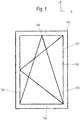
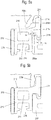
- FIG. 1a shows a side view of a sash 100. This extends in an X- / Y-plane. Perpendicular to the image plane, the Z-direction extends perpendicular to the main plane - the X- / Y-plane - of the window sash (see also Fig. 2 ).
- the window wing 100 has a casement 101 and a surface element 102.
- This surface element 102 may be formed, for example, as a glass pane, in particular as an insulating glass pane. It can also be designed as a metal plate or plastic plate. In the context of the implementation of the present invention, the embodiment is particularly preferred as insulating glass pane.
- the invention may be applied to a facade, there e.g. on fixed glazing or other fixed glazing for a building envelope opening, where there is no sash. Then the term wing frame is to be replaced by frame.
- the sash 101 is formed circumferentially closed in a preferred embodiment. It has a rectangular shape.
- the sash 101 is out here four mutually perpendicularly oriented composite profiles, the frame members or frame sections 103-106 form, composed.
- the frame profiles 103 - 106 each have a main extension direction in which they run. In light metal profiles, this is usually a direction of production of the light metal profiles, which can be done for example by extrusion.
- FIG. 12 shows a state in which the surface element 102 is correctly oriented so that its edge sides extend parallel to the frame rails 103-106.
- the frame members 103-106 are preferably formed the same in cross section.
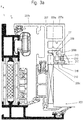
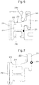
- FIG. 2 shows, on the one hand, a section through the frame rail 105 of the casement 101 on the one hand and, on the other hand, also shows a section through a frame rail 151 of a window frame 150, not shown here, on which the casement 101 is movably mounted.
- Both the frame members 103-105 and the frame members 120 of the frame are formed here as composite profiles. Where composite profiles are used, these have at least one metal shell, in particular a light metal, preferably aluminum shell 107. They also have at least one insulating profile 108 disposed thereon, which may preferably be made of plastic. The Kunststoffsoff insulating profile 108 extends in the assembled state here parallel to a peripheral edge side of the surface element 102.
- the composite profiles may have other elements such as another metal shell (only provided here on the frame).
- the surface element 102 extends flat in the main plane X / Y of the Fig. 1a parallel to the picture plane of the Fig. 1 and perpendicular to the image plane of the FIG. 2 is aligned.
- the metal shell 107 may be constructed in various ways. Preferably, it has a first region 107a which extends adjacent to the surface element 102 and a second integrally connected region 107b which extends beyond the peripheral edge of the surface element and partially - for example with a web, the window frame 150 in the closed state ( like here in Fig. 2 also shown) can overlap.
- the metal shell 107 is perpendicular to the image plane of the FIG. 2 and extending parallel to the respective frame spar 103 Groove for an adapter profile - ie an "Adapterprofilingnut 109" (in short: “groove 109") - on.
- the groove 109 is formed undercut and is formed perpendicular to the surface element open. Laterally of the opening 109a of the adapter profile groove 109, two webs 109b, 109c extending in the X / Y plane extend (ie parallel to the main plane of the surface element 102).
- the adapter profile 110 has a here in section the Fig. 2 in about T-shaped foot 111.
- the foot 111 is inserted into the undercut Adapterprofilnut 109 and engages behind the webs 109b and 109c.
- the adapter profile 110 has been inserted into the groove of the metal shell 107 like a dovetail and / or pivoted in.
- This connection is not shear resistant.
- the adapter profile 110 is additionally connected to the metal shell 107 with a material-penetrating connection V, such as a screw or rivet or a pin or the like, in order to stably fix it to the metal shell 107.
- An adapter profile 110 or preferably each adapter profile 110 also has an adhesive surface 112 oriented parallel to one of the two main surfaces of the surface element 102 or here parallel to the plane X / Y. This is here formed on a profile head 113, which has a hollow chamber 114 here.
- the profile head 113 extends from the T-shaped foot on both sides of the opening of the groove 109 and rests on the webs 109b, c on their side facing away from the actual groove 109 side.
- an adhesive layer 115 is applied on the adhesive surface 112 of the adapter profile 110 in the form of a double-sided adhesive tape.
- the surface element 102 has been pressed with an edge region of one of its two main surfaces onto this adhesive layer 115, in particular onto the double-sided adhesive tape.
- the adapter profile 110 connects the metal shell 107 and the surface element 102, in particular the insulating glass pane, to one another. The wing is thus additionally stabilized overall.
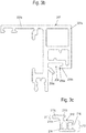
- the sash of the Fig. 3 can by type of Fig. 2 be constructed. Deviating from Fig. 2 is the definition of the adapter profile on the metal shell. Therefore, the show Figures 4ff , only this portion of the metal shell 207 and the adapter profile 210th
- a fixed glazing can also be realized.
- the adapter profile and the associated metal shell can also form part of a window frame. It will be described below a wing frame. This is a preferred example of the invention but not mandatory. The terms glare and sash are so far interchangeable.
- the metal shell 207 in turn has a groove 209 for fixing the adapter profile 210 ( Fig. 3a . b, c ).
- This groove 209 is formed undercut and is formed perpendicular to the surface element open. Extending laterally of the opening 209a of the adapter profile groove 209 are two webs 209b, 209c which, in the final assembled state, in turn extend substantially in the X / Y plane (ie parallel to the main plane of the planar element 202).
- the adapter profile 210 is not fixed by an enforcing fastener such as a screw, a rivet or pins on the metal section 207 fixed but it is on the metal profile 207 with his foot 211 in the undercut groove 209 by a forming process without play form-fitting and possibly also firmly locked.
- an enforcing fastener such as a screw, a rivet or pins on the metal section 207 fixed but it is on the metal profile 207 with his foot 211 in the undercut groove 209 by a forming process without play form-fitting and possibly also firmly locked.
- the adapter profile 210 in turn has a section of the Fig. 3 in about T-shaped foot 211 on.
- the foot may alternatively be formed, for example, L-shaped.
- the adapter profile also has a profile head 213.
- the foot 211 engages positively in the groove 209.
- This provision can also be made in the manner of a circumferential frame with several of the frame spars and correspondingly many adapter profiles.
- one of the webs 209b is aligned laterally of the slot opening 209a of the groove 209 of the metal shell 207, preferably parallel to the X / Y plane.
- the other web 209c is at the beginning of the attachment ( Fig. 4a ) aligned obliquely to the X / Y plane.
- this web 209c protrudes obliquely in the direction of the adhesive surface 212.
- the T-shaped foot 211 is preferably not formed centrally under the profile head 213 but offset from the center thereof so that the one leg 211a of the foot 211 extends laterally beyond the profile head 213.
- the adapter profile 210 is prepositioned in the groove 209.
- the adapter profile 210 is prepositioned in the groove 209.
- similar to the connection of two parts of a dovetail joint into the groove 209 can be inserted laterally or it is - if possible - pivoted into the groove 209, so that is pre-positioned correctly in the main extension direction.
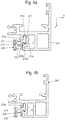
- a third step C at least one of the two webs 209b, 209c, which are formed laterally of the opening 209a of the groove 209, is applied in a reshaping manner to the T-shaped foot 211. This is done in such a way that the foot 211 is fixed without play in the groove 209 after forming, preferably fixed in a clamping manner.
- the forming of the web 209c can take place, for example, with a roller which rolls it against the foot 211 or rolls against it. Since the surface element 201 has not yet been adhered to the adhesive surface 212 in this state, it is possible to dive with a roller (not shown here) laterally past the profile head 213 of the adapter profile 201 and the web 209c to which also at least partially laterally to roll a foot 211 projecting the major surface of the surface element 201.
- the T-shaped foot 211 has a center leg 211a and two transverse legs 211b, c, which together form a kind of roof of the T.
- the foot 211 may also be L-shaped or otherwise, for example hook-shaped.
- the foot options can also be applied to these geometries and their equivalents.
- the center leg 211a and the one or both transverse legs 211b and c are each aligned at an angle to each other at an angle between 45 ° and 120 °.
- the center leg 211a and one or both of the transverse limbs 211b and 211c may have a roughened-in particular corrugated-surface at one or more points on their side facing the web 209c of the metal shell (see, for example, FIG Fig. 5a and 5b ).
- the molding of the web 209c to the foot 211 is such that the web in the final assembly state the foot 211 is pressed firmly against groove walls in two directions, so that essentially two contact areas / investment lines between the bridge to be formed on the one hand and the T-shaped foot and other groove walls are formed on the other hand.
- the web 209b After its deformation, the web 209b preferably exerts a force on the middle limb 211a, bears against it and presses it substantially parallel to the XY plane against a groove wall on the side of the groove 209 facing away from the web Web 209c after its forming on the other hand also a force on the transverse leg 211c from, is applied to this and presses this substantially parallel to the X- / Y-plane against a groove wall on the side facing away from the web 209c side.
- the profile head 213 has a face F213, which faces the web 209a of the metal shell 207 after step B) and is intended, after the forming of step C), to come into contact wholly or partly with the metal shell 207
- the profile foot also has a plurality of surfaces which is intended to come into the groove 209 of the metal shell 207 to the plant
- the profile head 213 and / or the foot 211 of the adapter profile are formed on one of these surfaces, preferably in surfaces F213 and F211 facing the inner or outer walls W209 and W209a of the groove 209 of the metal shell 207, such that the corresponding surfaces F213 and F211 or W209 and W209a of the adapter profile 210 and the metal shell 207 or the groove 209 after the pre-assembly of step B) are slightly obliquely aligned with each other, for example at an angle 0.5 ° ⁇ ( ⁇ 1 or ⁇ 2) ⁇ 25 °, in particular at an angle 1.5 ° ⁇ ( ⁇ 1 or ⁇ 2) ⁇ 15 ° , preferably at an angle 3 ° ⁇ ( ⁇ 1 or ⁇ 2) ⁇ 12 °.
- the profile head 213 here is substantially trapezoidal (and preferably not rectangular).
- the leg 211c of the foot 211 is also preferably substantially trapezoidal (and preferably non-rectangular).
- the leg 211c in the pre-assembled and not deformed state is slightly oblique to the corresponding contact surfaces inside and outside aligned with the groove (see also Fig. 5c ).
- angles ⁇ 1 and ⁇ 2 can be directed or opened in opposite directions (see Fig. 5a and 5c ), which can further increase the stability of the assembly after molding the web 209c.
- the surfaces F213 and F211 may be flat or curved, for example convex or concave (the latter indicated by dashed lines in the area of the surfaces 213a and 211a).
- the web 209c which is to be formed, in particular to be rolled, may have a projection 209d on one side, so that it bears against the web in a particularly defined manner. Corrugations on the foot and / or on the web can provide in the manner of a lock for an additional fixation of the adapter profile 210 in the groove ( Fig. 5a , b; 6a, 7a).
- one or more wires or bands - in particular sealing bands - 220, 221 can be laid, so that they are clamped in the final assembly state between the adapter profile 210 and the groove 209.
- This can additionally fix the adapter profile 210, in particular if the wire 220 is provided with cross-sectional changes in the longitudinal extent ( Fig. 6 ) and / or it may - in the case of sealing tapes 221 (FIG. 36, FIG. Fig. 7 ) an increased tightness against water or wind penetration in the region of the metal shell 207 in or on the groove 209 or can be achieved.
- the wire or seal 220, 221 may be preassembled in a groove or groove of the adapter profile 210.
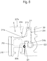
- one of the webs 209b of the foot 211 of the adapter profile 210 may have a widening end 223 which engages positively in a widened chamber area in the groove 209 in order to achieve an additional fixation of the foot 211 in the groove 209 (FIG. Fig. 8 ).
- This end 223 may also have a corrugation or the like.
- the adapter profile 210 is fixed by a forming process on the light metal shell 207.
- the setting is preferably carried out by a pure forming without a cleaving work step.
- the attachment of a forming tool takes place laterally outside a surface (perpendicular to the surface) of the surface, which is limited or occupied in the final assembly state of the surface element 202. This is in most cases equivalent to attaching the forming tool in a gap S between the profile head 213 of the adapter profile 210 and an adjacent web 207e of the metal shell 107th
- step after step B) and before or after step C) in a step D) the surface element 202 is adhered to the adhesive layer of the adapter profile.
- the adapter profile 210 has a lateral sealing groove 216.
- This sealing groove 216 is preferably open in the direction parallel to the surface element plane X / Y.
- a seal 217 can be used.
- This seal 217 is preferably inserted into the sealing groove 216 in a step E). It preferably seals on the one hand the gap between the surface element 201 and the adapter profile 210 and the adhesive layer 215. Preferably additionally or alternatively, it seals the gap between the adapter profile 210 and the metal shell 207. Then, two sealing functions are advantageously realized with the seal 217 in a simple manner.
- the adapter profile 210 may also have one or more hollow chambers 218 in the region of its profile head 213.
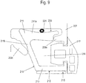
- FIG. 9 shows a section through a portion of a further variant according to the invention in a representation similar to Fig. 5a .
- the metal shell 207 has a groove 209 for fixing the adapter profile 210 (FIG. Fig. 3a . b, c ). It is preferably again, for example, as in Fig. 3 represented part of a composite profile, which is not otherwise shown here
- the groove 209 is again formed undercut and is formed perpendicular to the surface element open. Laterally of the opening 209a of the adapter profile groove 209, two webs 209b, 209c, which in turn in the final assembled state in turn extend essentially in the X / Y plane (ie parallel to the main plane of the planar element 202), also extend here.
- the adapter profile 210 is substantially U-shaped in cross-section with a substantially L-shaped foot 211 and with a substantially L-shaped profile head 13 with the adhesive surface 212, to which an adhesive layer 215 is applied.
- the two L of the foot 211 and the profile head 213 complement each other to a kind of U-shape.
- this adapter profile 210 is made of light metal.
- this adapter profile 210 is fixed to the metal profile 207 and the metal shell 207 with his foot 211 in the undercut groove 209 by a forming process without clearance form-fitting and possibly also non-positively.
- the one web 209c is formed on the one leg 211b of the two legs 211a and 211b of the foot 211, which merges later in the profile head 213.
- the leg 211b in turn has a roughened-in particular corrugated-surface on its side facing the web 209c of the metal shell 207 side.
- Forming of the web 209c on the foot 211 again takes place in such a way that the web 209a in the final assembly state presses the foot 211 firmly in two directions against groove walls, so that essentially two contact areas / contact lines between the web to be formed on the one hand and the foot, here the L-shaped foot and further groove walls are formed on the other hand.
- a lateral sealing groove 216 is formed between the adapter profile 210 and the metal shell 207 after forming the steps a), b) and c).
- This sealing groove 216 is preferably open in the direction parallel to the surface element plane X / Y.
- a seal 217 can be used.
- This seal 217 is preferably inserted into the sealing groove 216 in a step E). It preferably seals on the one hand the gap between the surface element 202 (not shown here) and the adapter profile 210 and the adhesive layer 215. Preferably additionally or alternatively, it seals the gap between the adapter profile 210 and the metal shell 207. Then with the seal 217 again advantageously two sealing functions are realized in a simple manner.
- a sealing tape 221 in turn seals a gap between the foot 211 of the adapter profile 210 and a groove wall of the groove 209.
- Fig. 9 the shapes of the groove 209 and the adapter profile 210 can be varied in many ways and that the terms of the profile head 213 and the groove 209 are not too narrow but are to be interpreted broadly.
- the adapter profile could also be F- or E-shaped and / or the foot 211 could be formed in this way.
- the groove may have a T-shaped cross section, but could also have a different cross section.
Landscapes
- Engineering & Computer Science (AREA)
- Civil Engineering (AREA)
- Structural Engineering (AREA)
- Securing Of Glass Panes Or The Like (AREA)
Applications Claiming Priority (1)
| Application Number | Priority Date | Filing Date | Title |
|---|---|---|---|
| DE102018109030.7A DE102018109030A1 (de) | 2018-04-17 | 2018-04-17 | Verfahren zur Festlegung eines Adapterprofils an einem Rahmenprofil eines Rahmens sowie Rahmen, Rahmenprofil und Adapterprofil |
Publications (2)
| Publication Number | Publication Date |
|---|---|
| EP3556983A1 true EP3556983A1 (fr) | 2019-10-23 |
| EP3556983B1 EP3556983B1 (fr) | 2023-08-23 |
Family
ID=66217889
Family Applications (1)
| Application Number | Title | Priority Date | Filing Date |
|---|---|---|---|
| EP19169755.6A Active EP3556983B1 (fr) | 2018-04-17 | 2019-04-17 | Procédé de détermination d'un profilé d'adaptateur sur un profilé d'un cadre ainsi que profilé de cadre |
Country Status (4)
| Country | Link |
|---|---|
| EP (1) | EP3556983B1 (fr) |
| DE (1) | DE102018109030A1 (fr) |
| ES (1) | ES2963393T3 (fr) |
| PL (1) | PL3556983T4 (fr) |
Citations (3)
| Publication number | Priority date | Publication date | Assignee | Title |
|---|---|---|---|---|
| DE9214959U1 (de) * | 1992-11-03 | 1993-02-25 | Metallbau Filser & Söhne GmbH & Co KG, 8045 Ismaning | Profilteil für einen Halterahmen eines flächigen Fassadenelementes |
| DE202008008660U1 (de) * | 2008-03-18 | 2008-09-11 | Sapa Rc System, N.V. | Fenster- oder Türprofil |
| DE102011017087A1 (de) * | 2011-04-14 | 2012-10-18 | Lohmann Gmbh & Co Kg | Adapterprofil für statische Glasverklebung |
Family Cites Families (1)
| Publication number | Priority date | Publication date | Assignee | Title |
|---|---|---|---|---|
| DE102016104583A1 (de) * | 2016-03-14 | 2017-09-14 | Dobler Metallbau Gmbh | Profilsystem für Flügelelemente von Fassaden |
-
2018
- 2018-04-17 DE DE102018109030.7A patent/DE102018109030A1/de not_active Withdrawn
-
2019
- 2019-04-17 EP EP19169755.6A patent/EP3556983B1/fr active Active
- 2019-04-17 ES ES19169755T patent/ES2963393T3/es active Active
- 2019-04-17 PL PL19169755.6T patent/PL3556983T4/pl unknown
Patent Citations (3)
| Publication number | Priority date | Publication date | Assignee | Title |
|---|---|---|---|---|
| DE9214959U1 (de) * | 1992-11-03 | 1993-02-25 | Metallbau Filser & Söhne GmbH & Co KG, 8045 Ismaning | Profilteil für einen Halterahmen eines flächigen Fassadenelementes |
| DE202008008660U1 (de) * | 2008-03-18 | 2008-09-11 | Sapa Rc System, N.V. | Fenster- oder Türprofil |
| DE102011017087A1 (de) * | 2011-04-14 | 2012-10-18 | Lohmann Gmbh & Co Kg | Adapterprofil für statische Glasverklebung |
Also Published As
| Publication number | Publication date |
|---|---|
| DE102018109030A1 (de) | 2019-10-17 |
| EP3556983B1 (fr) | 2023-08-23 |
| ES2963393T3 (es) | 2024-03-26 |
| PL3556983T3 (pl) | 2024-02-26 |
| PL3556983T4 (pl) | 2024-02-26 |
Similar Documents
| Publication | Publication Date | Title |
|---|---|---|
| EP3259428B1 (fr) | Dispositif d'étanchéité pour éléments de fenêtre et éléments de porte | |
| EP1568842A2 (fr) | Vantail pour porte de maison, porte avec un tel vantail et procédé de fabrication | |
| DE102008061709A1 (de) | Dichtungsprofil, Verbindungsvorrichtung und Dichtung | |
| AT523544B1 (de) | Kunststoff-Metall-Fenstersystem | |
| DE1509553A1 (de) | Fensterkonstruktion | |
| EP0995001B1 (fr) | Agencement d'une ferrure montee sur un cadre | |
| EP0716210A2 (fr) | Joint d'angle pour profilé en plastic | |
| EP0215456A1 (fr) | Profilé creux en matière plastique extrudée pour cadres de portes et fenêtres | |
| EP2935742A1 (fr) | Système de porte | |
| EP3556983B1 (fr) | Procédé de détermination d'un profilé d'adaptateur sur un profilé d'un cadre ainsi que profilé de cadre | |
| DE102004014598B4 (de) | Stoßverbinder zur Verbindung von Profilen | |
| EP4215709A1 (fr) | Baguette d'étanchéité pour un cadre composé de profilés individuels de cadre d'une fenêtre, d'une porte ou d'une façade | |
| DE102011008765A1 (de) | Profilanordnung, Rahmen und Rahmenanordnung | |
| DE19904695A1 (de) | Kämpferverbinder | |
| CH669972A5 (en) | Profiled door-sealing strip - has two-section transverse flange with stiffening rib on inside | |
| DE102016121068A1 (de) | Verbundprofil für eine Tür, ein Fenster oder ein Fassadenelement sowie Verfahren zur Herstellung des Verbundprofils | |
| EP3680438A1 (fr) | Profilé d'étanchéité pour un profilé de cadre et profilé de cadre | |
| DE102014103650A1 (de) | Verfahren sowie Profilsystem zur Herstellung von Gebäudefenstern, Gebäudetüren | |
| DE102013204944B4 (de) | Elastische Strangdichtung für Fenster, Türen oder dgl. | |
| EP2378045A2 (fr) | Disque en verre isolant | |
| DE102024122933A1 (de) | Abstandsclip für schwenkbare Türen und Fenster | |
| DE2810710B1 (de) | Einsatzrahmen zum Umruesten eines einfach verglasten Fluegelrahmens auf Isolierverglasung | |
| DE19942819A1 (de) | Profileinsatz für ein Hohlrahmenprofil und Verfahren zur Verbindung von Hohlrahmenprofilen miteinander | |
| EP1980702A2 (fr) | Construction de cadre pour fenêtres et/ou portes | |
| EP4191012A1 (fr) | Élément de fermeture d'ouverture de bâtiment et son procédé de fabrication |
Legal Events
| Date | Code | Title | Description |
|---|---|---|---|
| PUAI | Public reference made under article 153(3) epc to a published international application that has entered the european phase |
Free format text: ORIGINAL CODE: 0009012 |
|
| STAA | Information on the status of an ep patent application or granted ep patent |
Free format text: STATUS: THE APPLICATION HAS BEEN PUBLISHED |
|
| AK | Designated contracting states |
Kind code of ref document: A1 Designated state(s): AL AT BE BG CH CY CZ DE DK EE ES FI FR GB GR HR HU IE IS IT LI LT LU LV MC MK MT NL NO PL PT RO RS SE SI SK SM TR |
|
| AX | Request for extension of the european patent |
Extension state: BA ME |
|
| STAA | Information on the status of an ep patent application or granted ep patent |
Free format text: STATUS: REQUEST FOR EXAMINATION WAS MADE |
|
| 17P | Request for examination filed |
Effective date: 20200421 |
|
| RBV | Designated contracting states (corrected) |
Designated state(s): AL AT BE BG CH CY CZ DE DK EE ES FI FR GB GR HR HU IE IS IT LI LT LU LV MC MK MT NL NO PL PT RO RS SE SI SK SM TR |
|
| STAA | Information on the status of an ep patent application or granted ep patent |
Free format text: STATUS: EXAMINATION IS IN PROGRESS |
|
| 17Q | First examination report despatched |
Effective date: 20210716 |
|
| GRAP | Despatch of communication of intention to grant a patent |
Free format text: ORIGINAL CODE: EPIDOSNIGR1 |
|
| STAA | Information on the status of an ep patent application or granted ep patent |
Free format text: STATUS: GRANT OF PATENT IS INTENDED |
|
| INTG | Intention to grant announced |
Effective date: 20230314 |
|
| GRAS | Grant fee paid |
Free format text: ORIGINAL CODE: EPIDOSNIGR3 |
|
| GRAA | (expected) grant |
Free format text: ORIGINAL CODE: 0009210 |
|
| STAA | Information on the status of an ep patent application or granted ep patent |
Free format text: STATUS: THE PATENT HAS BEEN GRANTED |
|
| AK | Designated contracting states |
Kind code of ref document: B1 Designated state(s): AL AT BE BG CH CY CZ DE DK EE ES FI FR GB GR HR HU IE IS IT LI LT LU LV MC MK MT NL NO PL PT RO RS SE SI SK SM TR |
|
| REG | Reference to a national code |
Ref country code: GB Ref legal event code: FG4D Free format text: NOT ENGLISH |
|
| REG | Reference to a national code |
Ref country code: CH Ref legal event code: EP |
|
| REG | Reference to a national code |
Ref country code: IE Ref legal event code: FG4D Free format text: LANGUAGE OF EP DOCUMENT: GERMAN |
|
| REG | Reference to a national code |
Ref country code: DE Ref legal event code: R096 Ref document number: 502019009011 Country of ref document: DE |
|
| P01 | Opt-out of the competence of the unified patent court (upc) registered |
Effective date: 20231031 |
|
| REG | Reference to a national code |
Ref country code: LT Ref legal event code: MG9D |
|
| REG | Reference to a national code |
Ref country code: NL Ref legal event code: FP |
|
| PG25 | Lapsed in a contracting state [announced via postgrant information from national office to epo] |
Ref country code: GR Free format text: LAPSE BECAUSE OF FAILURE TO SUBMIT A TRANSLATION OF THE DESCRIPTION OR TO PAY THE FEE WITHIN THE PRESCRIBED TIME-LIMIT Effective date: 20231124 |
|
| PG25 | Lapsed in a contracting state [announced via postgrant information from national office to epo] |
Ref country code: IS Free format text: LAPSE BECAUSE OF FAILURE TO SUBMIT A TRANSLATION OF THE DESCRIPTION OR TO PAY THE FEE WITHIN THE PRESCRIBED TIME-LIMIT Effective date: 20231223 |
|
| PG25 | Lapsed in a contracting state [announced via postgrant information from national office to epo] |
Ref country code: SE Free format text: LAPSE BECAUSE OF FAILURE TO SUBMIT A TRANSLATION OF THE DESCRIPTION OR TO PAY THE FEE WITHIN THE PRESCRIBED TIME-LIMIT Effective date: 20230823 Ref country code: RS Free format text: LAPSE BECAUSE OF FAILURE TO SUBMIT A TRANSLATION OF THE DESCRIPTION OR TO PAY THE FEE WITHIN THE PRESCRIBED TIME-LIMIT Effective date: 20230823 Ref country code: PT Free format text: LAPSE BECAUSE OF FAILURE TO SUBMIT A TRANSLATION OF THE DESCRIPTION OR TO PAY THE FEE WITHIN THE PRESCRIBED TIME-LIMIT Effective date: 20231226 Ref country code: NO Free format text: LAPSE BECAUSE OF FAILURE TO SUBMIT A TRANSLATION OF THE DESCRIPTION OR TO PAY THE FEE WITHIN THE PRESCRIBED TIME-LIMIT Effective date: 20231123 Ref country code: LV Free format text: LAPSE BECAUSE OF FAILURE TO SUBMIT A TRANSLATION OF THE DESCRIPTION OR TO PAY THE FEE WITHIN THE PRESCRIBED TIME-LIMIT Effective date: 20230823 Ref country code: LT Free format text: LAPSE BECAUSE OF FAILURE TO SUBMIT A TRANSLATION OF THE DESCRIPTION OR TO PAY THE FEE WITHIN THE PRESCRIBED TIME-LIMIT Effective date: 20230823 Ref country code: IS Free format text: LAPSE BECAUSE OF FAILURE TO SUBMIT A TRANSLATION OF THE DESCRIPTION OR TO PAY THE FEE WITHIN THE PRESCRIBED TIME-LIMIT Effective date: 20231223 Ref country code: HR Free format text: LAPSE BECAUSE OF FAILURE TO SUBMIT A TRANSLATION OF THE DESCRIPTION OR TO PAY THE FEE WITHIN THE PRESCRIBED TIME-LIMIT Effective date: 20230823 Ref country code: GR Free format text: LAPSE BECAUSE OF FAILURE TO SUBMIT A TRANSLATION OF THE DESCRIPTION OR TO PAY THE FEE WITHIN THE PRESCRIBED TIME-LIMIT Effective date: 20231124 Ref country code: FI Free format text: LAPSE BECAUSE OF FAILURE TO SUBMIT A TRANSLATION OF THE DESCRIPTION OR TO PAY THE FEE WITHIN THE PRESCRIBED TIME-LIMIT Effective date: 20230823 |
|
| REG | Reference to a national code |
Ref country code: ES Ref legal event code: FG2A Ref document number: 2963393 Country of ref document: ES Kind code of ref document: T3 Effective date: 20240326 |
|
| PG25 | Lapsed in a contracting state [announced via postgrant information from national office to epo] |
Ref country code: SM Free format text: LAPSE BECAUSE OF FAILURE TO SUBMIT A TRANSLATION OF THE DESCRIPTION OR TO PAY THE FEE WITHIN THE PRESCRIBED TIME-LIMIT Effective date: 20230823 Ref country code: RO Free format text: LAPSE BECAUSE OF FAILURE TO SUBMIT A TRANSLATION OF THE DESCRIPTION OR TO PAY THE FEE WITHIN THE PRESCRIBED TIME-LIMIT Effective date: 20230823 Ref country code: EE Free format text: LAPSE BECAUSE OF FAILURE TO SUBMIT A TRANSLATION OF THE DESCRIPTION OR TO PAY THE FEE WITHIN THE PRESCRIBED TIME-LIMIT Effective date: 20230823 Ref country code: DK Free format text: LAPSE BECAUSE OF FAILURE TO SUBMIT A TRANSLATION OF THE DESCRIPTION OR TO PAY THE FEE WITHIN THE PRESCRIBED TIME-LIMIT Effective date: 20230823 Ref country code: CZ Free format text: LAPSE BECAUSE OF FAILURE TO SUBMIT A TRANSLATION OF THE DESCRIPTION OR TO PAY THE FEE WITHIN THE PRESCRIBED TIME-LIMIT Effective date: 20230823 Ref country code: SK Free format text: LAPSE BECAUSE OF FAILURE TO SUBMIT A TRANSLATION OF THE DESCRIPTION OR TO PAY THE FEE WITHIN THE PRESCRIBED TIME-LIMIT Effective date: 20230823 |
|
| REG | Reference to a national code |
Ref country code: DE Ref legal event code: R097 Ref document number: 502019009011 Country of ref document: DE |
|
| PLBE | No opposition filed within time limit |
Free format text: ORIGINAL CODE: 0009261 |
|
| STAA | Information on the status of an ep patent application or granted ep patent |
Free format text: STATUS: NO OPPOSITION FILED WITHIN TIME LIMIT |
|
| 26N | No opposition filed |
Effective date: 20240524 |
|
| PG25 | Lapsed in a contracting state [announced via postgrant information from national office to epo] |
Ref country code: SI Free format text: LAPSE BECAUSE OF FAILURE TO SUBMIT A TRANSLATION OF THE DESCRIPTION OR TO PAY THE FEE WITHIN THE PRESCRIBED TIME-LIMIT Effective date: 20230823 |
|
| PG25 | Lapsed in a contracting state [announced via postgrant information from national office to epo] |
Ref country code: BG Free format text: LAPSE BECAUSE OF FAILURE TO SUBMIT A TRANSLATION OF THE DESCRIPTION OR TO PAY THE FEE WITHIN THE PRESCRIBED TIME-LIMIT Effective date: 20230823 |
|
| PG25 | Lapsed in a contracting state [announced via postgrant information from national office to epo] |
Ref country code: MC Free format text: LAPSE BECAUSE OF FAILURE TO SUBMIT A TRANSLATION OF THE DESCRIPTION OR TO PAY THE FEE WITHIN THE PRESCRIBED TIME-LIMIT Effective date: 20230823 |
|
| PG25 | Lapsed in a contracting state [announced via postgrant information from national office to epo] |
Ref country code: MC Free format text: LAPSE BECAUSE OF FAILURE TO SUBMIT A TRANSLATION OF THE DESCRIPTION OR TO PAY THE FEE WITHIN THE PRESCRIBED TIME-LIMIT Effective date: 20230823 Ref country code: BG Free format text: LAPSE BECAUSE OF FAILURE TO SUBMIT A TRANSLATION OF THE DESCRIPTION OR TO PAY THE FEE WITHIN THE PRESCRIBED TIME-LIMIT Effective date: 20230823 |
|
| REG | Reference to a national code |
Ref country code: CH Ref legal event code: PL |
|
| PG25 | Lapsed in a contracting state [announced via postgrant information from national office to epo] |
Ref country code: LU Free format text: LAPSE BECAUSE OF NON-PAYMENT OF DUE FEES Effective date: 20240417 |
|
| REG | Reference to a national code |
Ref country code: BE Ref legal event code: MM Effective date: 20240430 |
|
| PG25 | Lapsed in a contracting state [announced via postgrant information from national office to epo] |
Ref country code: LU Free format text: LAPSE BECAUSE OF NON-PAYMENT OF DUE FEES Effective date: 20240417 |
|
| PG25 | Lapsed in a contracting state [announced via postgrant information from national office to epo] |
Ref country code: BE Free format text: LAPSE BECAUSE OF NON-PAYMENT OF DUE FEES Effective date: 20240430 |
|
| PG25 | Lapsed in a contracting state [announced via postgrant information from national office to epo] |
Ref country code: BE Free format text: LAPSE BECAUSE OF NON-PAYMENT OF DUE FEES Effective date: 20240430 Ref country code: CH Free format text: LAPSE BECAUSE OF NON-PAYMENT OF DUE FEES Effective date: 20240430 |
|
| PG25 | Lapsed in a contracting state [announced via postgrant information from national office to epo] |
Ref country code: IE Free format text: LAPSE BECAUSE OF NON-PAYMENT OF DUE FEES Effective date: 20240417 |
|
| PGFP | Annual fee paid to national office [announced via postgrant information from national office to epo] |
Ref country code: PL Payment date: 20250314 Year of fee payment: 7 |
|
| PGFP | Annual fee paid to national office [announced via postgrant information from national office to epo] |
Ref country code: GB Payment date: 20250313 Year of fee payment: 7 |
|
| PGFP | Annual fee paid to national office [announced via postgrant information from national office to epo] |
Ref country code: NL Payment date: 20250422 Year of fee payment: 7 |
|
| PGFP | Annual fee paid to national office [announced via postgrant information from national office to epo] |
Ref country code: DE Payment date: 20250317 Year of fee payment: 7 |
|
| PGFP | Annual fee paid to national office [announced via postgrant information from national office to epo] |
Ref country code: ES Payment date: 20250519 Year of fee payment: 7 |
|
| PGFP | Annual fee paid to national office [announced via postgrant information from national office to epo] |
Ref country code: IT Payment date: 20250430 Year of fee payment: 7 |
|
| PGFP | Annual fee paid to national office [announced via postgrant information from national office to epo] |
Ref country code: FR Payment date: 20250415 Year of fee payment: 7 |
|
| PGFP | Annual fee paid to national office [announced via postgrant information from national office to epo] |
Ref country code: AT Payment date: 20250422 Year of fee payment: 7 |
|
| PG25 | Lapsed in a contracting state [announced via postgrant information from national office to epo] |
Ref country code: CY Free format text: LAPSE BECAUSE OF FAILURE TO SUBMIT A TRANSLATION OF THE DESCRIPTION OR TO PAY THE FEE WITHIN THE PRESCRIBED TIME-LIMIT; INVALID AB INITIO Effective date: 20190417 |
|
| PG25 | Lapsed in a contracting state [announced via postgrant information from national office to epo] |
Ref country code: HU Free format text: LAPSE BECAUSE OF FAILURE TO SUBMIT A TRANSLATION OF THE DESCRIPTION OR TO PAY THE FEE WITHIN THE PRESCRIBED TIME-LIMIT; INVALID AB INITIO Effective date: 20190417 |