EP3556983A1 - Frame and method for fixing an adapter profile on a frame profile of a frame, frame profile and adapter profile - Google Patents
Frame and method for fixing an adapter profile on a frame profile of a frame, frame profile and adapter profile Download PDFInfo
- Publication number
- EP3556983A1 EP3556983A1 EP19169755.6A EP19169755A EP3556983A1 EP 3556983 A1 EP3556983 A1 EP 3556983A1 EP 19169755 A EP19169755 A EP 19169755A EP 3556983 A1 EP3556983 A1 EP 3556983A1
- Authority
- EP
- European Patent Office
- Prior art keywords
- profile
- groove
- foot
- adapter
- adapter profile
- Prior art date
- Legal status (The legal status is an assumption and is not a legal conclusion. Google has not performed a legal analysis and makes no representation as to the accuracy of the status listed.)
- Granted
Links
Images


Classifications
-
- E—FIXED CONSTRUCTIONS
- E06—DOORS, WINDOWS, SHUTTERS, OR ROLLER BLINDS IN GENERAL; LADDERS
- E06B—FIXED OR MOVABLE CLOSURES FOR OPENINGS IN BUILDINGS, VEHICLES, FENCES OR LIKE ENCLOSURES IN GENERAL, e.g. DOORS, WINDOWS, BLINDS, GATES
- E06B3/00—Window sashes, door leaves, or like elements for closing wall or like openings; Layout of fixed or moving closures, e.g. windows in wall or like openings; Features of rigidly-mounted outer frames relating to the mounting of wing frames
- E06B3/54—Fixing of glass panes or like plates
- E06B3/56—Fixing of glass panes or like plates by means of putty, cement, or adhesives only
-
- E—FIXED CONSTRUCTIONS
- E06—DOORS, WINDOWS, SHUTTERS, OR ROLLER BLINDS IN GENERAL; LADDERS
- E06B—FIXED OR MOVABLE CLOSURES FOR OPENINGS IN BUILDINGS, VEHICLES, FENCES OR LIKE ENCLOSURES IN GENERAL, e.g. DOORS, WINDOWS, BLINDS, GATES
- E06B3/00—Window sashes, door leaves, or like elements for closing wall or like openings; Layout of fixed or moving closures, e.g. windows in wall or like openings; Features of rigidly-mounted outer frames relating to the mounting of wing frames
- E06B3/30—Coverings, e.g. protecting against weather, for decorative purposes
- E06B3/308—Wing frames covered on the outside by a rigidly-mounted outer frame
-
- E—FIXED CONSTRUCTIONS
- E06—DOORS, WINDOWS, SHUTTERS, OR ROLLER BLINDS IN GENERAL; LADDERS
- E06B—FIXED OR MOVABLE CLOSURES FOR OPENINGS IN BUILDINGS, VEHICLES, FENCES OR LIKE ENCLOSURES IN GENERAL, e.g. DOORS, WINDOWS, BLINDS, GATES
- E06B3/00—Window sashes, door leaves, or like elements for closing wall or like openings; Layout of fixed or moving closures, e.g. windows in wall or like openings; Features of rigidly-mounted outer frames relating to the mounting of wing frames
- E06B3/04—Wing frames not characterised by the manner of movement
- E06B3/263—Frames with special provision for insulation
- E06B3/2632—Frames with special provision for insulation with arrangements reducing the heat transmission, other than an interruption in a metal section
- E06B2003/26325—Frames with special provision for insulation with arrangements reducing the heat transmission, other than an interruption in a metal section the convection or radiation in a hollow space being reduced, e.g. by subdividing the hollow space
- E06B2003/2633—Frames with special provision for insulation with arrangements reducing the heat transmission, other than an interruption in a metal section the convection or radiation in a hollow space being reduced, e.g. by subdividing the hollow space the insulating strips between the metal sections having ribs extending into the hollow space
-
- E—FIXED CONSTRUCTIONS
- E06—DOORS, WINDOWS, SHUTTERS, OR ROLLER BLINDS IN GENERAL; LADDERS
- E06B—FIXED OR MOVABLE CLOSURES FOR OPENINGS IN BUILDINGS, VEHICLES, FENCES OR LIKE ENCLOSURES IN GENERAL, e.g. DOORS, WINDOWS, BLINDS, GATES
- E06B3/00—Window sashes, door leaves, or like elements for closing wall or like openings; Layout of fixed or moving closures, e.g. windows in wall or like openings; Features of rigidly-mounted outer frames relating to the mounting of wing frames
- E06B3/54—Fixing of glass panes or like plates
- E06B3/58—Fixing of glass panes or like plates by means of borders, cleats, or the like
- E06B3/62—Fixing of glass panes or like plates by means of borders, cleats, or the like of rubber-like elastic cleats
- E06B2003/6238—Fixing of glass panes or like plates by means of borders, cleats, or the like of rubber-like elastic cleats having extra functions
- E06B2003/6244—Fixing of glass panes or like plates by means of borders, cleats, or the like of rubber-like elastic cleats having extra functions with extra parts sealing against the bottom of the glazing rebate or against the edge of the pane
-
- E—FIXED CONSTRUCTIONS
- E06—DOORS, WINDOWS, SHUTTERS, OR ROLLER BLINDS IN GENERAL; LADDERS
- E06B—FIXED OR MOVABLE CLOSURES FOR OPENINGS IN BUILDINGS, VEHICLES, FENCES OR LIKE ENCLOSURES IN GENERAL, e.g. DOORS, WINDOWS, BLINDS, GATES
- E06B3/00—Window sashes, door leaves, or like elements for closing wall or like openings; Layout of fixed or moving closures, e.g. windows in wall or like openings; Features of rigidly-mounted outer frames relating to the mounting of wing frames
- E06B3/04—Wing frames not characterised by the manner of movement
- E06B3/263—Frames with special provision for insulation
- E06B3/26301—Frames with special provision for insulation with prefabricated insulating strips between two metal section members
- E06B3/26303—Frames with special provision for insulation with prefabricated insulating strips between two metal section members with thin strips, e.g. defining a hollow space between the metal section members
Definitions
- the invention relates to a method for fixing an adapter profile on a frame profile of a frame of a door, a window or a facade, a frame profile and a frame, a frame profile and an adapter profile.
- door and window are used synonymously. Where elements of a window are described, the descriptions of these elements of the prior art and the invention can also be related to a door, as this differs from a door only by the frame, which is not reflected in the claims here.
- the invention facade there, e.g. on a fixed glazing, when there is no sash. Then the term wing frame is to be replaced by frame.
- wing frames of sashes which are composed of light metal composite profiles, in particular aluminum composite profiles
- a surface element such as an insulating glass or the like adhesive
- an adapter profile - which is also usually made of light metal, in particular aluminum - in a groove of a light metal shell of the sash profile or the encircling sash profiles used.
- an adhesive layer is applied to the circumferentially closed frame with the preassembled adapter profiles in the area of the adapter profiles.
- the adapter profiles each have an adhesive surface, wherein these adhesive surfaces of the adapter profiles are aligned parallel to the plane of the surface element in the preassembled state on the circumferentially closed wing frame.
- the surface element is aligned for attachment to the adhesive surface parallel to this adhesive surface. This can be done for example by means of suction cups. Then the window is carefully lowered exactly aligned with the adhesive surfaces and glued to the adapter profiles.
- the invention has the object to remedy this problem.
- the invention solves this problem by the method of claim 1 and by the frame profile of claim 12, the frame of claim 13 and the adapter profile of claim 14th
- foot is not too narrow but are to be understood in a broader sense of functional.
- the foot can be T- or L-shaped but also have a different shape.
- the foot is the part of the adapter profile that lies inside the groove.
- the notion of groove is also not too narrow.
- the groove is in the broader sense an undercut behind the reshaped web, in which the foot protrudes, but it can also, for example, in the strict sense be formed as a cross-section I-L or T-shaped or otherwise dovetail-like groove.
- the profile head is the part of the adapter profile which rests outside the groove on the metal shell and has the adhesive surface.
- the adapter profile is determined by a forming process on the metal shell, preferably fixed without play form-fitting manner to the metal shell.
- the setting is preferably carried out by a pure forming without a cleaving work step.
- the pre-positioning of the foot of the adapter profile in the groove may include insertion and / or pivoting of the foot of the adapter profile in the groove.
- step B) of pre-positioning the foot of the adapter profile in the groove comprises a pre-positioning of the adapter profile in a main extension direction of the metal shell.
- the reshaping can be done in various ways. It is particularly simple if the step C) of the forming includes a rolling of a web on the foot of the adapter profile.
- the forming of the web of the metal shell for fixing to the foot of the adapter profile is such that the web is pressed in the final assembly state the foot in two directions against Nutwandungen, so that essentially two investment areas / investment lines between the to be formed Web on the one hand and the preferably L- or T-shaped foot and groove walls of the groove are formed on the other hand. Because such a particularly secure and defined determination of the foot of the adapter profile is achieved in the groove.
- the determination of the adapter profile in the groove can be further supported by the fact that in the step C) of the forming further locking of the metal shell - in particular of the web to be rolled - and / or another wall of the Groove takes place on at least one corrugation of the foot.
- Kinematic reversals of this principle are also feasible.
- the preferably L- or T-shaped foot is not formed centrally under the profile head but offset to the center thereof, so that the one leg of the foot extends laterally beyond the profile head, so that the Forming the step C) takes place laterally of a surface of the surface element.
- the forming is particularly simple and safe to carry out.
- the attachment of a forming tool takes place laterally outside the surface, which is limited in the final assembly state of the surface element. This is in most cases equivalent to attaching the forming tool in a gap S between the profile head of the adapter profile and an adjacent web of the metal shell. Because the forming can be done so well that the adhesive layer can not be damaged.
- step B) and before or after step C the surface element can be adhesively bonded to the adhesive layer of the adapter profile.
- the adhesive layer which is preferably formed as a double-sided adhesive tape, from which the protective layers are removed before the surface element is adhered.
- a seal is inserted into a sealing groove of the adapter profile to form a gap between the surface element and the adapter profile and the adhesive layer and / or a gap between the Seal adapter profile and metal shell.
- the invention also provides a frame profile according to claim 12 with at least one metal shell or preferably at least one metal profile and at least one adapter profile for adhesive attachment of a surface element which is fixed to the metal shell of the frame profile by a method according to one of claims 1 to 11.
- the invention also provides according to claim 13, a frame of a plurality of frame profiles according to claim 12, which is designed circumferentially closed and on the adapter profiles, a surface element is glued, wherein the advantages of claims 1 and 11 are also implemented or realized.
- the invention also provides an adapter profile for such a frame profile according to claim 14, comprising a profile head with an adhesive surface and with a foot for insertion into a groove in the frame profile, wherein the profile head has an alignable to the web of the metal shell surface, which is intended after the forming of step C) wholly or partially come to rest on the metal shell and wherein the profiled foot also has a plurality of surfaces which is intended to come into contact with the groove of the metal shell, wherein the profile head and the foot of the adapter profile respectively at one of these surfaces, preferably at facing to inner or outer walls of the metal shell surfaces F213 and F211 are oriented obliquely to the corresponding walls before forming.
- the profile head and / or the foot of the adapter profile at one of its surfaces preferably pointing to the inner or outer walls of the groove of the metal shell surfaces obliquely at an angle 0.5 ° ⁇ 1 ⁇ 25 ° , in particular at an angle 1.5 ° ⁇ 1 ⁇ 15 °, preferably at an angle 3 ° ⁇ 1 ⁇ 2 ⁇ 12 ° (and / or at an angle of 0.5 ° ⁇ 2 ⁇ 25 °, in particular at an angle 1, 5 ° ⁇ 2 ⁇ 15 °, preferably at an angle 3 ° ⁇ 2 ⁇ 2 ⁇ 12 °) is aligned to the corresponding walls / are.
- the respective surfaces of the profile head and the adapter profile may be flat or curved - in particular concave or convex curved - be formed.
- angles ⁇ 1 and ⁇ 2 run open in opposite directions.
- the profile head and the foot are formed substantially trapezoidal, wherein the two angles ⁇ 1 and ⁇ 2 are open in opposite directions and each essentially describe the deviation to a rectangular shape.
- the metal shell and the adapter profile may preferably consist of light metal, in particular one or different aluminum alloys.
- the adapter profile can - but less preferred - also consist of a different material.
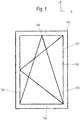
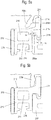
- FIG. 1a shows a side view of a sash 100. This extends in an X- / Y-plane. Perpendicular to the image plane, the Z-direction extends perpendicular to the main plane - the X- / Y-plane - of the window sash (see also Fig. 2 ).
- the window wing 100 has a casement 101 and a surface element 102.
- This surface element 102 may be formed, for example, as a glass pane, in particular as an insulating glass pane. It can also be designed as a metal plate or plastic plate. In the context of the implementation of the present invention, the embodiment is particularly preferred as insulating glass pane.
- the invention may be applied to a facade, there e.g. on fixed glazing or other fixed glazing for a building envelope opening, where there is no sash. Then the term wing frame is to be replaced by frame.
- the sash 101 is formed circumferentially closed in a preferred embodiment. It has a rectangular shape.
- the sash 101 is out here four mutually perpendicularly oriented composite profiles, the frame members or frame sections 103-106 form, composed.
- the frame profiles 103 - 106 each have a main extension direction in which they run. In light metal profiles, this is usually a direction of production of the light metal profiles, which can be done for example by extrusion.
- FIG. 12 shows a state in which the surface element 102 is correctly oriented so that its edge sides extend parallel to the frame rails 103-106.
- the frame members 103-106 are preferably formed the same in cross section.
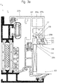
- FIG. 2 shows, on the one hand, a section through the frame rail 105 of the casement 101 on the one hand and, on the other hand, also shows a section through a frame rail 151 of a window frame 150, not shown here, on which the casement 101 is movably mounted.
- Both the frame members 103-105 and the frame members 120 of the frame are formed here as composite profiles. Where composite profiles are used, these have at least one metal shell, in particular a light metal, preferably aluminum shell 107. They also have at least one insulating profile 108 disposed thereon, which may preferably be made of plastic. The Kunststoffsoff insulating profile 108 extends in the assembled state here parallel to a peripheral edge side of the surface element 102.
- the composite profiles may have other elements such as another metal shell (only provided here on the frame).
- the surface element 102 extends flat in the main plane X / Y of the Fig. 1a parallel to the picture plane of the Fig. 1 and perpendicular to the image plane of the FIG. 2 is aligned.
- the metal shell 107 may be constructed in various ways. Preferably, it has a first region 107a which extends adjacent to the surface element 102 and a second integrally connected region 107b which extends beyond the peripheral edge of the surface element and partially - for example with a web, the window frame 150 in the closed state ( like here in Fig. 2 also shown) can overlap.
- the metal shell 107 is perpendicular to the image plane of the FIG. 2 and extending parallel to the respective frame spar 103 Groove for an adapter profile - ie an "Adapterprofilingnut 109" (in short: “groove 109") - on.
- the groove 109 is formed undercut and is formed perpendicular to the surface element open. Laterally of the opening 109a of the adapter profile groove 109, two webs 109b, 109c extending in the X / Y plane extend (ie parallel to the main plane of the surface element 102).
- the adapter profile 110 has a here in section the Fig. 2 in about T-shaped foot 111.
- the foot 111 is inserted into the undercut Adapterprofilnut 109 and engages behind the webs 109b and 109c.
- the adapter profile 110 has been inserted into the groove of the metal shell 107 like a dovetail and / or pivoted in.
- This connection is not shear resistant.
- the adapter profile 110 is additionally connected to the metal shell 107 with a material-penetrating connection V, such as a screw or rivet or a pin or the like, in order to stably fix it to the metal shell 107.
- An adapter profile 110 or preferably each adapter profile 110 also has an adhesive surface 112 oriented parallel to one of the two main surfaces of the surface element 102 or here parallel to the plane X / Y. This is here formed on a profile head 113, which has a hollow chamber 114 here.
- the profile head 113 extends from the T-shaped foot on both sides of the opening of the groove 109 and rests on the webs 109b, c on their side facing away from the actual groove 109 side.
- an adhesive layer 115 is applied on the adhesive surface 112 of the adapter profile 110 in the form of a double-sided adhesive tape.
- the surface element 102 has been pressed with an edge region of one of its two main surfaces onto this adhesive layer 115, in particular onto the double-sided adhesive tape.
- the adapter profile 110 connects the metal shell 107 and the surface element 102, in particular the insulating glass pane, to one another. The wing is thus additionally stabilized overall.
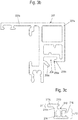
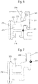
- the sash of the Fig. 3 can by type of Fig. 2 be constructed. Deviating from Fig. 2 is the definition of the adapter profile on the metal shell. Therefore, the show Figures 4ff , only this portion of the metal shell 207 and the adapter profile 210th
- a fixed glazing can also be realized.
- the adapter profile and the associated metal shell can also form part of a window frame. It will be described below a wing frame. This is a preferred example of the invention but not mandatory. The terms glare and sash are so far interchangeable.
- the metal shell 207 in turn has a groove 209 for fixing the adapter profile 210 ( Fig. 3a . b, c ).
- This groove 209 is formed undercut and is formed perpendicular to the surface element open. Extending laterally of the opening 209a of the adapter profile groove 209 are two webs 209b, 209c which, in the final assembled state, in turn extend substantially in the X / Y plane (ie parallel to the main plane of the planar element 202).
- the adapter profile 210 is not fixed by an enforcing fastener such as a screw, a rivet or pins on the metal section 207 fixed but it is on the metal profile 207 with his foot 211 in the undercut groove 209 by a forming process without play form-fitting and possibly also firmly locked.
- an enforcing fastener such as a screw, a rivet or pins on the metal section 207 fixed but it is on the metal profile 207 with his foot 211 in the undercut groove 209 by a forming process without play form-fitting and possibly also firmly locked.
- the adapter profile 210 in turn has a section of the Fig. 3 in about T-shaped foot 211 on.
- the foot may alternatively be formed, for example, L-shaped.
- the adapter profile also has a profile head 213.
- the foot 211 engages positively in the groove 209.
- This provision can also be made in the manner of a circumferential frame with several of the frame spars and correspondingly many adapter profiles.
- one of the webs 209b is aligned laterally of the slot opening 209a of the groove 209 of the metal shell 207, preferably parallel to the X / Y plane.
- the other web 209c is at the beginning of the attachment ( Fig. 4a ) aligned obliquely to the X / Y plane.
- this web 209c protrudes obliquely in the direction of the adhesive surface 212.
- the T-shaped foot 211 is preferably not formed centrally under the profile head 213 but offset from the center thereof so that the one leg 211a of the foot 211 extends laterally beyond the profile head 213.
- the adapter profile 210 is prepositioned in the groove 209.
- the adapter profile 210 is prepositioned in the groove 209.
- similar to the connection of two parts of a dovetail joint into the groove 209 can be inserted laterally or it is - if possible - pivoted into the groove 209, so that is pre-positioned correctly in the main extension direction.
- a third step C at least one of the two webs 209b, 209c, which are formed laterally of the opening 209a of the groove 209, is applied in a reshaping manner to the T-shaped foot 211. This is done in such a way that the foot 211 is fixed without play in the groove 209 after forming, preferably fixed in a clamping manner.
- the forming of the web 209c can take place, for example, with a roller which rolls it against the foot 211 or rolls against it. Since the surface element 201 has not yet been adhered to the adhesive surface 212 in this state, it is possible to dive with a roller (not shown here) laterally past the profile head 213 of the adapter profile 201 and the web 209c to which also at least partially laterally to roll a foot 211 projecting the major surface of the surface element 201.
- the T-shaped foot 211 has a center leg 211a and two transverse legs 211b, c, which together form a kind of roof of the T.
- the foot 211 may also be L-shaped or otherwise, for example hook-shaped.
- the foot options can also be applied to these geometries and their equivalents.
- the center leg 211a and the one or both transverse legs 211b and c are each aligned at an angle to each other at an angle between 45 ° and 120 °.
- the center leg 211a and one or both of the transverse limbs 211b and 211c may have a roughened-in particular corrugated-surface at one or more points on their side facing the web 209c of the metal shell (see, for example, FIG Fig. 5a and 5b ).
- the molding of the web 209c to the foot 211 is such that the web in the final assembly state the foot 211 is pressed firmly against groove walls in two directions, so that essentially two contact areas / investment lines between the bridge to be formed on the one hand and the T-shaped foot and other groove walls are formed on the other hand.
- the web 209b After its deformation, the web 209b preferably exerts a force on the middle limb 211a, bears against it and presses it substantially parallel to the XY plane against a groove wall on the side of the groove 209 facing away from the web Web 209c after its forming on the other hand also a force on the transverse leg 211c from, is applied to this and presses this substantially parallel to the X- / Y-plane against a groove wall on the side facing away from the web 209c side.
- the profile head 213 has a face F213, which faces the web 209a of the metal shell 207 after step B) and is intended, after the forming of step C), to come into contact wholly or partly with the metal shell 207
- the profile foot also has a plurality of surfaces which is intended to come into the groove 209 of the metal shell 207 to the plant
- the profile head 213 and / or the foot 211 of the adapter profile are formed on one of these surfaces, preferably in surfaces F213 and F211 facing the inner or outer walls W209 and W209a of the groove 209 of the metal shell 207, such that the corresponding surfaces F213 and F211 or W209 and W209a of the adapter profile 210 and the metal shell 207 or the groove 209 after the pre-assembly of step B) are slightly obliquely aligned with each other, for example at an angle 0.5 ° ⁇ ( ⁇ 1 or ⁇ 2) ⁇ 25 °, in particular at an angle 1.5 ° ⁇ ( ⁇ 1 or ⁇ 2) ⁇ 15 ° , preferably at an angle 3 ° ⁇ ( ⁇ 1 or ⁇ 2) ⁇ 12 °.
- the profile head 213 here is substantially trapezoidal (and preferably not rectangular).
- the leg 211c of the foot 211 is also preferably substantially trapezoidal (and preferably non-rectangular).
- the leg 211c in the pre-assembled and not deformed state is slightly oblique to the corresponding contact surfaces inside and outside aligned with the groove (see also Fig. 5c ).
- angles ⁇ 1 and ⁇ 2 can be directed or opened in opposite directions (see Fig. 5a and 5c ), which can further increase the stability of the assembly after molding the web 209c.
- the surfaces F213 and F211 may be flat or curved, for example convex or concave (the latter indicated by dashed lines in the area of the surfaces 213a and 211a).
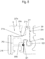
- the web 209c which is to be formed, in particular to be rolled, may have a projection 209d on one side, so that it bears against the web in a particularly defined manner. Corrugations on the foot and / or on the web can provide in the manner of a lock for an additional fixation of the adapter profile 210 in the groove ( Fig. 5a , b; 6a, 7a).
- one or more wires or bands - in particular sealing bands - 220, 221 can be laid, so that they are clamped in the final assembly state between the adapter profile 210 and the groove 209.
- This can additionally fix the adapter profile 210, in particular if the wire 220 is provided with cross-sectional changes in the longitudinal extent ( Fig. 6 ) and / or it may - in the case of sealing tapes 221 (FIG. 36, FIG. Fig. 7 ) an increased tightness against water or wind penetration in the region of the metal shell 207 in or on the groove 209 or can be achieved.
- the wire or seal 220, 221 may be preassembled in a groove or groove of the adapter profile 210.
- one of the webs 209b of the foot 211 of the adapter profile 210 may have a widening end 223 which engages positively in a widened chamber area in the groove 209 in order to achieve an additional fixation of the foot 211 in the groove 209 (FIG. Fig. 8 ).
- This end 223 may also have a corrugation or the like.
- the adapter profile 210 is fixed by a forming process on the light metal shell 207.
- the setting is preferably carried out by a pure forming without a cleaving work step.
- the attachment of a forming tool takes place laterally outside a surface (perpendicular to the surface) of the surface, which is limited or occupied in the final assembly state of the surface element 202. This is in most cases equivalent to attaching the forming tool in a gap S between the profile head 213 of the adapter profile 210 and an adjacent web 207e of the metal shell 107th
- step after step B) and before or after step C) in a step D) the surface element 202 is adhered to the adhesive layer of the adapter profile.
- the adapter profile 210 has a lateral sealing groove 216.
- This sealing groove 216 is preferably open in the direction parallel to the surface element plane X / Y.
- a seal 217 can be used.
- This seal 217 is preferably inserted into the sealing groove 216 in a step E). It preferably seals on the one hand the gap between the surface element 201 and the adapter profile 210 and the adhesive layer 215. Preferably additionally or alternatively, it seals the gap between the adapter profile 210 and the metal shell 207. Then, two sealing functions are advantageously realized with the seal 217 in a simple manner.
- the adapter profile 210 may also have one or more hollow chambers 218 in the region of its profile head 213.
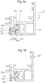
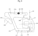
- FIG. 9 shows a section through a portion of a further variant according to the invention in a representation similar to Fig. 5a .
- the metal shell 207 has a groove 209 for fixing the adapter profile 210 (FIG. Fig. 3a . b, c ). It is preferably again, for example, as in Fig. 3 represented part of a composite profile, which is not otherwise shown here
- the groove 209 is again formed undercut and is formed perpendicular to the surface element open. Laterally of the opening 209a of the adapter profile groove 209, two webs 209b, 209c, which in turn in the final assembled state in turn extend essentially in the X / Y plane (ie parallel to the main plane of the planar element 202), also extend here.
- the adapter profile 210 is substantially U-shaped in cross-section with a substantially L-shaped foot 211 and with a substantially L-shaped profile head 13 with the adhesive surface 212, to which an adhesive layer 215 is applied.
- the two L of the foot 211 and the profile head 213 complement each other to a kind of U-shape.
- this adapter profile 210 is made of light metal.
- this adapter profile 210 is fixed to the metal profile 207 and the metal shell 207 with his foot 211 in the undercut groove 209 by a forming process without clearance form-fitting and possibly also non-positively.
- the one web 209c is formed on the one leg 211b of the two legs 211a and 211b of the foot 211, which merges later in the profile head 213.
- the leg 211b in turn has a roughened-in particular corrugated-surface on its side facing the web 209c of the metal shell 207 side.
- Forming of the web 209c on the foot 211 again takes place in such a way that the web 209a in the final assembly state presses the foot 211 firmly in two directions against groove walls, so that essentially two contact areas / contact lines between the web to be formed on the one hand and the foot, here the L-shaped foot and further groove walls are formed on the other hand.
- a lateral sealing groove 216 is formed between the adapter profile 210 and the metal shell 207 after forming the steps a), b) and c).
- This sealing groove 216 is preferably open in the direction parallel to the surface element plane X / Y.
- a seal 217 can be used.
- This seal 217 is preferably inserted into the sealing groove 216 in a step E). It preferably seals on the one hand the gap between the surface element 202 (not shown here) and the adapter profile 210 and the adhesive layer 215. Preferably additionally or alternatively, it seals the gap between the adapter profile 210 and the metal shell 207. Then with the seal 217 again advantageously two sealing functions are realized in a simple manner.
- a sealing tape 221 in turn seals a gap between the foot 211 of the adapter profile 210 and a groove wall of the groove 209.
- Fig. 9 the shapes of the groove 209 and the adapter profile 210 can be varied in many ways and that the terms of the profile head 213 and the groove 209 are not too narrow but are to be interpreted broadly.
- the adapter profile could also be F- or E-shaped and / or the foot 211 could be formed in this way.
- the groove may have a T-shaped cross section, but could also have a different cross section.
Landscapes
- Engineering & Computer Science (AREA)
- Civil Engineering (AREA)
- Structural Engineering (AREA)
- Securing Of Glass Panes Or The Like (AREA)
Abstract
Ein Verfahren zur Festlegung eines Adapterprofils (210) an einer Metallschale (207) eines Rahmenprofils (203 - 206) für einen Rahmen einer Tür, eines Fensters oder einer Fassade, mit zumindest folgenden Schritten:Schritt A): Bereitstellen der Metallschale (207) mit einer Nut (209) und Bereitstellen des Adapterprofils (210) mit einem Fuß (211) zum Einsetzen in die Nut (209) und mit einem Profilkopf (213), der eine Klebefläche (212) aufweist, die mit einer Klebeschicht (215) bereits versehen ist oder noch versehen wird, wobei wenigstens ein Steg (209c) seitlich einer Öffnung (209a) der Nut (209) ausgebildet ist;Schritt B): Vorpositionieren des Fußes (211) des Adapterprofils (210) in der Nut (209);Schritt C): umformendes Anlegen zumindest des Steges (209c) seitlich der Öffnung (209a) der Nut (209) an den Fuß (211), wobei der Fuß durch das Umformen spielfrei in der Nut (209) festgelegt wird, vorzugsweise klemmend festgelegt wird.A method for fixing an adapter profile (210) on a metal shell (207) of a frame profile (203-206) for a frame of a door, a window or a facade, with at least the following steps: Step A): providing the metal shell (207) with a groove (209) and providing the adapter profile (210) with a foot (211) for insertion into the groove (209) and with a profile head (213) which has an adhesive surface (212) which is already covered with an adhesive layer (215) is or will be provided, at least one web (209c) being formed on the side of an opening (209a) of the groove (209); Step B): prepositioning of the foot (211) of the adapter profile (210) in the groove (209); Step C): reshaping application of at least the web (209c) to the side of the opening (209a) of the groove (209) on the foot (211), the foot being fixed in the groove (209) without play, preferably in a clamping manner .
Description
Die Erfindung betrifft ein Verfahren zur Festlegung eines Adapterprofils an einem Rahmenprofil eines Rahmens einer Tür, eines Fensters oder einer Fassade, ein Rahmenprofil sowie einen Rahmen, ein Rahmenprofil und ein Adapterprofil.The invention relates to a method for fixing an adapter profile on a frame profile of a frame of a door, a window or a facade, a frame profile and a frame, a frame profile and an adapter profile.
In dieser Schrift werden die Begriffe Tür und Fenster synonym verwendet. Dort, wo Elemente eines Fensters beschreiben werden, können die Beschreibungen dieser Elemente zum Stand der Technik und zur Erfindung auch auf eine Tür bezogen werden, da diese sich nur durch den Blendrahmen von einer Tür unterscheidet, was sich hier in den Ansprüchen nicht niederschlägt. Ebenso kann die Erfindung Fassade, dort z.B. an einer Festverglasung, angewendet werden, wenn es keinen Flügelrahmen gibt. Dann ist der Begriff Flügelrahmen durch Blendrahmen zu ersetzen.In this document, the terms door and window are used synonymously. Where elements of a window are described, the descriptions of these elements of the prior art and the invention can also be related to a door, as this differs from a door only by the frame, which is not reflected in the claims here. Likewise, the invention facade, there, e.g. on a fixed glazing, when there is no sash. Then the term wing frame is to be replaced by frame.
Es ist bekannt, an Flügelrahmen von Fensterflügeln, die aus Leichtmetall-Verbundprofilen, insbesondere Aluminium-Verbundprofilen, zu einem umfangsgeschlossenen Rahmen zusammengesetzt sind, ein Flächenelement wie eine Isolierglasscheibe oder dergleichen klebend zu befestigen. Zur klebenden Befestigung des Flächenelementes wird in der Regel ein Adapterprofil - das in der Regel ebenfalls aus Leichtmetall, insbesondere Aluminium, besteht - in eine Nut einer Leichtmetallschale des Flügelrahmenprofils bzw. der umlaufenden Flügelrahmenprofile eingesetzt. Sodann wird auf den umfangsgeschlossenen Rahmen mit den vormontierten Adapterprofilen im Bereich der Adapterprofile eine Klebeschicht aufgebracht. Die Adapterprofile weisen dazu jeweils eine Klebefläche auf, wobei diese Klebeflächen der Adapterprofile im vormontierten Zustand am umlaufend geschlossenen Flügelrahmen parallel zur Ebene des Flächenelementes ausgerichtet sind. Das Flächenelement wird zur Befestigung auf der Klebefläche parallel zu dieser Klebefläche ausgerichtet. Dies kann beispielsweise mittels Saugnäpfen erfolgen. Sodann wird das Fenster vorsichtig exakt ausgerichtet auf die Klebeflächen abgesenkt und mit den Adapterprofilen verklebt.It is known to adhere to wing frames of sashes, which are composed of light metal composite profiles, in particular aluminum composite profiles, to a circumferentially closed frame, a surface element such as an insulating glass or the like adhesive. For adhesive attachment of the surface element is usually an adapter profile - which is also usually made of light metal, in particular aluminum - in a groove of a light metal shell of the sash profile or the encircling sash profiles used. Then, an adhesive layer is applied to the circumferentially closed frame with the preassembled adapter profiles in the area of the adapter profiles. For this purpose, the adapter profiles each have an adhesive surface, wherein these adhesive surfaces of the adapter profiles are aligned parallel to the plane of the surface element in the preassembled state on the circumferentially closed wing frame. The surface element is aligned for attachment to the adhesive surface parallel to this adhesive surface. This can be done for example by means of suction cups. Then the window is carefully lowered exactly aligned with the adhesive surfaces and glued to the adapter profiles.
Um die Stabilität dieser Anordnung zu erhöhen, ist es bekannt, die Adapterprofile mittels Befestigungselementen, insbesondere mittels Schraub- oder Stiftverbindungen, die umfangsverteilt an den Adapterprofilen am vormontierten Rahmen eingebracht werden, zusätzlich an den Verbundprofilen zu befestigen.In order to increase the stability of this arrangement, it is known to attach the adapter profiles by means of fastening elements, in particular by means of screw or pin connections, which are circumferentially distributed to the adapter profiles on the pre-assembled frame, in addition to the composite profiles.
Daran ist nachteilig, dass die Schrauben oder Metallstifte oder dergleichen erst nach dem Aufbringen der Klebeschicht auf der Klebefläche der Adapterprofile befestigt werden können. Dies führt dazu, dass die Klebeflächen quasi Störstellen aufweisen, die durch das Einbringen der Befestigungsmittel in die Klebeschicht eingebracht werden.This is disadvantageous in that the screws or metal pins or the like can be attached to the adhesive surface of the adapter profiles only after the application of the adhesive layer. As a result, the adhesive surfaces virtually have defects which are introduced into the adhesive layer by the introduction of the fastening means.
Die Erfindung hat die Aufgabe, dieses Problem zu beheben.The invention has the object to remedy this problem.
Die Erfindung löst diese Aufgabe durch das Verfahren des Anspruchs 1 sowie durch das Rahmenprofil des Anspruchs 12, den Rahmen des Anspruchs 13 und das Adapterprofil des Anspruchs 14.The invention solves this problem by the method of claim 1 and by the frame profile of claim 12, the frame of claim 13 and the adapter profile of claim 14th
Anspruch 1 schafft ein Verfahren zur Festlegung eines Adapterprofils an einer Metallschale eines Rahmenprofils für einen Rahmen einer Tür, eines Fensters oder einer Fassade, mit zumindest folgenden Schritten:
- Schritt A): Bereitstellen der Metallschale mit einer Nut und Bereitstellen des Adapterprofils mit einem Fuß zum Einsetzen in die Nut und mit einem Profilkopf, der eine Klebefläche aufweist, die mit einer Klebeschicht bereits versehen ist oder noch versehen wird, wobei wenigstens ein Steg oder zwei Stege seitlich einer Öffnung der Nut ausgebildet sind;
- Schritt B): Vorpositionieren des Fußes des Adapterprofils in der Nut;
- Schritt C): umformendes Anlegen zumindest des einen Steges oder zumindest eines Steges seitlich der Öffnung der Nut an den Fuß, wobei der Fuß durch das Umformen spielfrei in der Nut festgelegt wird, vorzugsweise klemmend festgelegt wird.
- Step A): Providing the metal shell with a groove and providing the adapter profile with a foot for insertion into the groove and with a profile head having an adhesive surface which is or will be provided with an adhesive layer, wherein at least one web or two Webs are formed laterally of an opening of the groove;
- Step B): pre-positioning the foot of the adapter profile in the groove;
- Step C): forming applying at least one web or at least one web laterally of the opening of the groove on the foot, wherein the foot is determined by the forming play in the groove, is preferably determined by clamping.
Sofern unbestimmte Artikel wie "ein" verwendet werden, sind dies in der Regel keine beschränkende Zahlenangaben sondern im Sinne von "mindestens einer oder mehr" zu verstehen.If indefinite articles such as "a" are used, these are generally not meant as limiting figures but as "at least one or more".
Die Begriffe "Fuß", "Kopf" und "Nut" sind nicht zu eng sondern in einem eher breiten Sinne funktional zu verstehen. Der Fuß kann T- oder L-förmig ausgebildet sein aber auch eine andere Form aufweisen. Der Fuß ist der Teil des Adapterprofils, das innerhalb der Nut liegt. Der Begriff der Nut ist ebenfalls nicht zu eng zu fassen. Die Nut ist im weiteren Sinne ein Hinterschnitt hinter dem umzuformenden Steg, in welchen der Fuß hineinragt, sie kann aber beispielsweise auch im engeren Sinne als im Querschnitt I- L- oder T-förmige oder sonstig schwalbenschanzartige Nut ausgebildet sein. Der Profilkopf ist der Teil des Adapterprofils, der außerhalb der Nut auf der Metallschale aufliegt und die Klebefläche aufweist.The terms "foot", "head" and "groove" are not too narrow but are to be understood in a broader sense of functional. The foot can be T- or L-shaped but also have a different shape. The foot is the part of the adapter profile that lies inside the groove. The notion of groove is also not too narrow. The groove is in the broader sense an undercut behind the reshaped web, in which the foot protrudes, but it can also, for example, in the strict sense be formed as a cross-section I-L or T-shaped or otherwise dovetail-like groove. The profile head is the part of the adapter profile which rests outside the groove on the metal shell and has the adhesive surface.
Erfindungsgemäß ist somit vorgesehen, dass das Adapterprofil durch einen Umformprozess an der Metallschale festgelegt wird, vorzugsweise spielfrei formschlüssig an der Metallschale festgelegt wird. Vorzugsweise erfolgt das Festlegen durch ein reines Umformen ohne einen spaltabhebenden Arbeitsschritt. Dies hat den Vorteil, dass die eigentliche Klebeschicht zum Aufkleben des Flächenelementes nicht durch das Fixieren des Adapterprofils an der Metallschale (die insbesondere ein Metallprofil ist) beschädigt wird, so dass ein wesentliches Problem des Standes der Technik beseitigt wird. Es kann zwar theoretisch ergänzend weiter eine Schraubverbindung oder dgl. vorgesehen sein. Notwendig ist dies aber nicht.According to the invention it is thus provided that the adapter profile is determined by a forming process on the metal shell, preferably fixed without play form-fitting manner to the metal shell. The setting is preferably carried out by a pure forming without a cleaving work step. This has the advantage that the actual adhesive layer for adhering the surface element is not damaged by the fixing of the adapter profile on the metal shell (which is in particular a metal profile), so that a major problem of the prior art is eliminated. In theory, it may additionally be provided a screw connection or the like. But this is not necessary.
Dabei kann das Vorpositionieren des Fußes des Adapterprofils in der Nut ein Einschieben und/oder Einschwenken des Fußes des Adapterprofils in die Nut umfassen.In this case, the pre-positioning of the foot of the adapter profile in the groove may include insertion and / or pivoting of the foot of the adapter profile in the groove.
Es kann ferner bevorzugt vorgesehen sein, dass der Schritt B) des Vorpositionierens des Fußes des Adapterprofils in der Nut ein Vorpositionieren des Adapterprofils in einer Haupterstreckungsrichtung der Metallschale umfasst.It may further be preferred that the step B) of pre-positioning the foot of the adapter profile in the groove comprises a pre-positioning of the adapter profile in a main extension direction of the metal shell.
Das Umformen an sich kann auf verschiedene Weise erfolgen. Besonders einfach ist, wenn der Schritt C) des Umformens ein Anrollen eines Steges an den Fußes des Adapterprofils umfasst.The reshaping can be done in various ways. It is particularly simple if the step C) of the forming includes a rolling of a web on the foot of the adapter profile.
Es kann bevorzugt vorgesehen sein, dass das Umformen des Stegs der Metallschale zum Festlegen an dem Fuß des Adapterprofils derart erfolgt, dass der Steg im Endmontagezustand den Fuß in zwei Richtungen fest gegen Nutwandungen gepresst ist, so dass im Wesentlichen zwei Anlagebereiche/Anlagelinien zwischen dem anzuformenden Steg einerseits und dem vorzugsweise L- oder T-förmigen Fuß und Nutwandungen der Nut anderseits gebildet werden. Denn derart wird eine besonders sichere und definierte Festlegung des Fußes des Adapterprofils in der Nut erreicht.It can preferably be provided that the forming of the web of the metal shell for fixing to the foot of the adapter profile is such that the web is pressed in the final assembly state the foot in two directions against Nutwandungen, so that essentially two investment areas / investment lines between the to be formed Web on the one hand and the preferably L- or T-shaped foot and groove walls of the groove are formed on the other hand. Because such a particularly secure and defined determination of the foot of the adapter profile is achieved in the groove.
Die Festlegung des Adapterprofils in der Nut kann weiter dadurch unterstützt werden, dass bei dem Schritt C) des Umformens ferner ein Verrasten der Metallschale - insbesondere des anzurollenden Steges - und/oder einer anderen Wandung der Nut an wenigstens einer Riffelung des Fußes erfolgt. Kinematische Umkehrungen dieses Prinzips sind ebenfalls realisierbar.The determination of the adapter profile in the groove can be further supported by the fact that in the step C) of the forming further locking of the metal shell - in particular of the web to be rolled - and / or another wall of the Groove takes place on at least one corrugation of the foot. Kinematic reversals of this principle are also feasible.
Nach einer besonders bevorzugten Variante kann vorgesehen sein, dass der bevorzugt L- oder T-förmige Fuß nicht mittig unter dem Profilkopf ausgebildet ist sondern versetzt zu dessen Mitte, so dass sich der eine Schenkel des Fußes seitlich über den Profilkopf hinaus erstreckt, so dass das Umformen des Schrittes C) seitlich einer Fläche des Flächenelementes erfolgt. Denn derart ist das Umformen besonders einfach und sicher durchführbar. Somit erfolgt hier das Anbringen eines Umformwerkzeugs seitlich außerhalb der Fläche, welche im Endmontagezustand von dem Flächenelement begrenzt wird. Dies ist in den allermeisten Fällen gleichbedeutend mit einem Anbringen des Umformwerkzeuges in einem Spalt S zwischen dem Profilkopf des Adapterprofils und einem benachbarten Steg der Metallschale. Denn derart kann das Umformen besonders gut derart erfolgen, dass die Klebeschicht nicht beschädigt werden kann.According to a particularly preferred variant it can be provided that the preferably L- or T-shaped foot is not formed centrally under the profile head but offset to the center thereof, so that the one leg of the foot extends laterally beyond the profile head, so that the Forming the step C) takes place laterally of a surface of the surface element. For in this way the forming is particularly simple and safe to carry out. Thus, the attachment of a forming tool takes place laterally outside the surface, which is limited in the final assembly state of the surface element. This is in most cases equivalent to attaching the forming tool in a gap S between the profile head of the adapter profile and an adjacent web of the metal shell. Because the forming can be done so well that the adhesive layer can not be damaged.
Sodann kann in einem weiteren Verfahrensschritt nach Schritt B) und vor oder nach Schritt C) das Flächenelement auf die Klebeschicht des Adapterprofils aufgeklebt werden. Dann ist es vorteilhaft, wenn bei dem Bereitstellen nach Schritt A) oder nach dem Schritt B) ein umlaufener Rahmen aus Verbundprofilen mit Metallschalen und Adapterprofilen bereitgestellt wird.Then, in a further method step after step B) and before or after step C), the surface element can be adhesively bonded to the adhesive layer of the adapter profile. Then it is advantageous if, when providing step A) or after step B), a peripheral frame of composite profiles with metal shells and adapter profiles is provided.
Zuvor muss natürlich die Klebeschicht aufgebracht worden sein, die vorzugsweise als Doppelklebeband ausgebildet ist, von dem die Schutzschichten entfernt werden, bevor das Flächenelement aufgeklebt wird.Of course, before the adhesive layer must be applied, which is preferably formed as a double-sided adhesive tape, from which the protective layers are removed before the surface element is adhered.
Es kann weiter vorteilhaft vorgesehen sein, dass in einem weiteren Verfahrensschritt nach Schritt D) in einem Schritt E) eine Dichtung in eine Dichtungsnut des Adapterprofils eingesetzt wird, um einen Spalt zwischen dem Flächenelement und dem Adapterprofil sowie der Klebeschicht und/oder einen Spalt zwischen dem Adapterprofil und der Metallschale abzudichten.It can also be advantageously provided that in a further method step after step D) in a step E), a seal is inserted into a sealing groove of the adapter profile to form a gap between the surface element and the adapter profile and the adhesive layer and / or a gap between the Seal adapter profile and metal shell.
Die Erfindung schafft nach Anspruch 12 auch ein Rahmenprofil mit wenigstens einer Metallschale bzw. vorzugsweise wenigstens einem Metallprofil und wenigstens einem Adapterprofil zur klebenden Befestigung eines Flächenelementes, das an der Metallschale des Rahmenprofils nach einem Verfahren nach einem der Ansprüche 1 bis 11 festgelegt ist.The invention also provides a frame profile according to claim 12 with at least one metal shell or preferably at least one metal profile and at least one adapter profile for adhesive attachment of a surface element which is fixed to the metal shell of the frame profile by a method according to one of claims 1 to 11.
Die Erfindung schafft auch nach Anspruch 13 einen Rahmen aus mehreren Rahmenprofilen nach Anspruch 12, der umfangsgeschlossen ausgebildet ist und auf dessen Adapterprofile ein Flächenelement aufgeklebt ist, wobei die Vorteile der Ansprüche 1 und 11 ebenfalls umgesetzt bzw. realisiert werden.The invention also provides according to claim 13, a frame of a plurality of frame profiles according to claim 12, which is designed circumferentially closed and on the adapter profiles, a surface element is glued, wherein the advantages of claims 1 and 11 are also implemented or realized.
Die Erfindung schafft zudem ein Adapterprofil für ein solches Rahmenprofil nach Anspruch 14, mit einem Profilkopf mit einer Klebefläche und mit einem Fuß zum Einsetzen in eine Nut in des Rahmenprofils, wobei der Profilkopf eine zum Steg der Metallschale ausrichtbare Fläche aufweist, die dazu bestimmt ist, nach dem Umformen des Schrittes C) ganz oder teilweise an der Metallschale zur Anlage zu kommen und wobei der Profilfuß zudem mehrere Flächen aufweist, die dazu bestimmt ist, in der Nut der Metallschale zur Anlage zu kommen, wobei der Profilkopf und der Fuß des Adapterprofils jeweils an einer dieser Flächen, vorzugsweise an zu inneren oder äußeren Wandungen der Metallschale zeigenden Flächen F213 und F211 vor dem Umformen schräg zu den korrespondierenden Wandungen ausgerichtet sind.The invention also provides an adapter profile for such a frame profile according to claim 14, comprising a profile head with an adhesive surface and with a foot for insertion into a groove in the frame profile, wherein the profile head has an alignable to the web of the metal shell surface, which is intended after the forming of step C) wholly or partially come to rest on the metal shell and wherein the profiled foot also has a plurality of surfaces which is intended to come into contact with the groove of the metal shell, wherein the profile head and the foot of the adapter profile respectively at one of these surfaces, preferably at facing to inner or outer walls of the metal shell surfaces F213 and F211 are oriented obliquely to the corresponding walls before forming.
Derart kann nach dem Umformen ein besonders fester, definierter Sitz des Adapterprofils an und in der Metallschale erreicht werden.In this way, after forming a particularly firm, defined seat of the adapter profile can be achieved on and in the metal shell.
Anders ausgedrückt kann ist vorzugweise vorgesehen, dass
- der Abstand von Punkten bzw. Linien P1 und P3 der Fläche F211 zu Punkten bzw. Linien P2 und P4 der korrespondierenden Fläche W209 ungleich ist, und/oder dass
- der Abstand von Punkten bzw. Linien P1' und P3' der Fläche F213 zu Punkten bzw. Linien P2' und P4' der korrespondierenden Fläche W209a ungleich ist.
- the distance of points or lines P1 and P3 of the surface F211 to points or lines P2 and P4 of the corresponding surface W209 is unequal, and / or that
- the distance of points or lines P1 'and P3' of the surface F213 to points or lines P2 'and P4' of the corresponding surface W209a is unequal.
Zur Weiterbildung kann vorteilhaft weiter vorteilhaft vorgesehen sein, dass der Profilkopf und/oder der Fuß des Adapterprofils an einer ihrer Flächen, vorzugsweise an zu inneren oder äußeren Wandungen der Nut der Metallschale zeigenden Flächen schräg in einem Winkel 0,5° < α1 < 25°, insbesondere in einem Winkel 1,5° < α1 < 15°, vorzugweise in einem Winkel 3° < α1 α2 < 12° (und/oder in einem Winkel 0,5° < α2 < 25°, insbesondere in einem Winkel 1,5° < α2 < 15°, vorzugweise in einem Winkel 3° < α2 α2 < 12°)zu den korrespondierenden Wandungen ausgerichtet ist/sind. Die jeweiligen Flächen des Profilkopfes und des Adapterprofils können eben oder gekrümmt - insbesondere konkav oder konvex gekrümmt - ausgebildet sein.For further development can advantageously be further advantageously provided that the profile head and / or the foot of the adapter profile at one of its surfaces, preferably pointing to the inner or outer walls of the groove of the metal shell surfaces obliquely at an angle 0.5 ° <α1 <25 ° , in particular at an angle 1.5 ° <α1 <15 °, preferably at an angle 3 ° <α1 α2 <12 ° (and / or at an angle of 0.5 ° <α2 <25 °, in particular at an angle 1, 5 ° <α2 <15 °, preferably at an angle 3 ° <α2 α2 <12 °) is aligned to the corresponding walls / are. The respective surfaces of the profile head and the adapter profile may be flat or curved - in particular concave or convex curved - be formed.
Es kann zur Optimierung des festen Sitzes weiter vorteilhaft vorgesehen sein, dass die Winkel α1 und α2 gegensinnig geöffnet verlaufen.It can be further advantageously provided for optimizing the tight fit, that the angles α1 and α2 run open in opposite directions.
Es ist auch vorteilhaft, wenn der Profilkopf und der Fuß im Wesentlichen trapezfömig ausgebildet sind, wobei die beiden Winkel α1 und α2 gegensinnig geöffnet sind und jeweils im Wesentlichen die Abweichung zu einer Rechteckform beschreiben.It is also advantageous if the profile head and the foot are formed substantially trapezoidal, wherein the two angles α1 and α2 are open in opposite directions and each essentially describe the deviation to a rectangular shape.
Die Metallschale und das Adapterprofil können bevorzugt aus Leichtmetall, insbesondere aus einer oder verschiedenen Aluminiumlegierungen, bestehen. Das Adapterprofil kann aber - weniger bevorzugt - auch aus einem anderen Material bestehen.The metal shell and the adapter profile may preferably consist of light metal, in particular one or different aluminum alloys. The adapter profile can - but less preferred - also consist of a different material.
Vorteilhafte Ausgestaltung der Erfindung sind den übrigen Unteransprüchen zu entnehmen.Advantageous embodiment of the invention can be found in the remaining subclaims.
Nachfolgend wird die Erfindung unter Bezug auf die Figuren näher beschrieben. Diese Figuren zeigen bevorzugte Ausführungsbeispiele der Erfindung. Anzumerken ist, dass die Erfindung nicht auf diese Ausführungsbeispiele beschränkt werden kann, sodann dass auch andere, hier nicht gezeigte Ausführungsvarianten im Rahmen der Ansprüche realisierbar sind sowie Äquivalente und Abwandlungen der dargestellten Figuren, die Rahmen der Schutzbereiche liegen. Es zeigt:
- Figur 1:
- eine schematische Darstellung eines Fensterflügels in einer Seitenansicht;
- Figur 2:
- einen Schnitt durch einen Randbereich eines Rahmenholms und eines Flächenelementes eines Flügelrahmens eines bekannten Fensterflügels;
- Figur 3a:
- einen Schnitt durch einen Randbereich eines Rahmenholms und eines Flächenelementes eines Flügelrahmens eines erfindungsgemäßen Fensterflügels;
- Figur 3b:
- einen Schnitt durch ein Metallprofil bzw. eine Metallschale des Flügelrahmens aus
Fig. 3a ; - Figur 3a:
- einen Schnitt durch ein Adapterprofil des Flügelrahmens aus
Fig. 3a ; - Figur 4a:
- eine Metallschale des Flügelrahmens aus
Figur 3 mit einem vormontierten Adapterprofil; - Figur 4b:
- die Anordnung aus
Figur 4a in einem gegenüberFigur 4a späteren Zustand bei der Befestigung des Adapterprofils an der Leichtmetallschale; - Figur 5a
- eine Ausschnittsvergrößerung aus
Figur 4a ; - Figur 5b:
- eine Ausschnittsvergrößerung aus
Figur 4b ; - Figur 5c
- eine weitere Ausschnittsvergrößerung aus
Figur 4a , in welcher auch weitere Varianten der Erfindung dargestellt sind; - Figur 6:
- einen Ausschnitt einer erfindungsgemäßen Variante in einer Darstellung ähnlich zu
Fig. 5a ; - Figur 7; 8
- schematische Darstellungen zur Veranschaulichung verschiedener optionaler vorteilhafter Merkmale der Erfindung; und
- Figur 9:
- einen Ausschnitt einer weiteren erfindungsgemäßen Variante in einer Darstellung ähnlich zu
Fig. 5a .
- FIG. 1:
- a schematic representation of a window sash in a side view;
- FIG. 2:
- a section through an edge region of a frame spar and a surface element of a sash of a known window sash;
- FIG. 3a:
- a section through an edge region of a frame spar and a surface element of a sash of a window sash according to the invention;
- FIG. 3b:
- a section through a metal profile or a metal shell of the sash
Fig. 3a ; - FIG. 3a:
- a section through an adapter profile of the sash
Fig. 3a ; - FIG. 4a
- a metal shell of the sash
FIG. 3 with a preassembled adapter profile; - FIG. 4b:
- the arrangement
FIG. 4a in one oppositeFIG. 4a later state in the attachment of the adapter profile to the light metal shell; - FIG. 5a
- an excerpt from
FIG. 4a ; - FIG. 5b:
- an excerpt from
FIG. 4b ; - FIG. 5c
- another enlarged detail
FIG. 4a , in which also further variants of the invention are shown; - FIG. 6:
- a section of a variant according to the invention in a representation similar to
Fig. 5a ; - Figure 7; 8th
- schematic representations to illustrate various optional advantageous features of the invention; and
- FIG. 9:
- a section of another variant of the invention in a representation similar to
Fig. 5a ,
Der Fensterflügel 100 weist einen Flügelrahmen 101 auf und ein Flächenelement 102. Dieses Flächenelement 102 kann beispielsweise als Glasscheibe, insbesondere als Isolierglasscheibe ausgebildet sein. Es kann aber auch als Metallplatte oder Kunststoffplatte ausgebildet sein. Besonders bevorzugt ist im Rahmen der Umsetzung der vorliegenden Erfindung die Ausgestaltung als Isolierglasscheibe. Ebenso kann die Erfindung an einer Fassade, dort z.B. an einer Festverglasung oder an einer sonstigen Festverglasung für eine Gebäudehüllenöffnung, angewendet werden, wo es keinen Flügelrahmen gibt. Dann ist der Begriff Flügelrahmen nachfolgend durch Blendrahmen zu ersetzen.The
Der Flügelrahmen 101 ist in bevorzugter Ausgestaltung umfangsgeschlossen ausgebildet. Er weist eine rechteckige Form auf. Der Flügelrahmen 101 ist hier aus vier zueinander rechtwinklig ausgerichteten Verbundprofilen, die Rahmenholme bzw. Rahmenprofile 103-106 bilden, zusammengesetzt. Die Rahmenprofile 103 - 106 haben jeweils eine Haupterstreckungsrichtung, in welcher sie verlaufen. Bei Leichtmetallprofilen ist dies in der Regel eine Richtung der Fertigung der Leichtmetallprofile, die z.B. durch Strangpressen erfolgen kann.The
Sowohl die Rahmenholme 103 - 105 als auch die Rahmenholme 120 des Blendrahmens sind hier als Verbundprofile ausgebildet. Dort, wo Verbundprofile eingesetzt sind, weisen diese wenigstens eine Metallschale, insbesondere eine Leichtmetall-, vorzugsweise Aluminiumschale 107 auf. Sie weisen ferner wenigstens ein daran angeordnetes Isolierprofil 108 auf, das vorzugsweise aus Kunststoff bestehen kann. Das Kunstsoff-Isolierprofil 108 erstreckt sich im montierten Zustand hier parallel zu einer Umfangsrandseite des Flächenelements 102. Die Verbundprofile können noch weitere Elemente wie beispielsweise eine weitere Metallschale aufweisen (hier nur am Blendrahmen vorgesehen).Both the frame members 103-105 and the frame members 120 of the frame are formed here as composite profiles. Where composite profiles are used, these have at least one metal shell, in particular a light metal, preferably aluminum shell 107. They also have at least one insulating
Das Flächenelement 102 erstreckt sich flächig in der Haupterstreckungsebene X/Y der
In dem ersten Bereich 107a, der sich parallel zu der der Haupterstreckungsebene X/Y des Flächenelements 102 erstreckt, weist die Metallschale 107 eine sich senkrecht zur Bildebene der
Die Nut 109 ist hinterschnitten ausgebildet und ist senkrecht zum Flächenelement offen ausgebildet. Seitlich der Öffnung 109a der Adapterprofilnut 109 erstrecken sich zwei Stege 109b, 109c, die in der X-/Y-Ebene verlaufen (also parallel zur Hauptebene des Flächenelementes 102).The
In der Adapterprofilnut 109 ist ein Adapterprofil 110 festgelegt. Das Adapterprofil 110 weist dazu einen hier im Schnitt der
Derart ist das Adapterprofil 110 in die Nut der Metallschale 107 schwalbenschwanzähnlich eingeschoben und/oder eingeschwenkt worden. Diese Verbindung ist nicht schubfest. Nach dem Stand der Technik der
Ein Adapterprofil 110 oder vorzugsweise jedes Adapterprofil 110 weist ferner eine parallel zu einer der beiden Hauptflächen des Flächenelementes 102 bzw. hier parallel zu der Ebene X/Y ausgerichtete Klebefläche 112 auf. Diese ist hier an einem Profilkopf 113 ausgebildet, der hier eine Hohlkammer 114 aufweist. Der Profilkopf 113 erstreckt sich ausgehend von dem T-förmigen Fuß beidseits der Öffnung der Nut 109 und liegt auf den Stegen 109b, c auf deren von der eigentlichen Nut 109 abgewandten Seite auf.An
Auf die Klebefläche 112 ist eine Klebeschicht 115 aufgebracht. Die Klebeschicht 115 kann in Form eines doppelseitigen Klebebandes auf die Klebefläche 112 des Adapterprofils 110 aufgebracht sein. Das Flächenelement 102 ist mit einem Randbereich einer seiner beiden Hauptflächen auf diese Klebeschicht 115, insbesondere auf das doppelseitige Klebeband, aufgepresst worden. Derart verbindet das Adapterprofil 110 die Metallschale 107 und das Flächenelement 102, insbesondere die Isolierglasscheibe, miteinander. Der Flügel wird dadurch insgesamt ergänzend stabilisiert.On the
Daran ist nachteilig, dass zwingend die Schraub- oder Stiftverbindung V zur zusätzlichen Stabilisierung des Adapterprofils 110 notwendig ist.This is disadvantageous that mandatory the screw or pin connection V for additional stabilization of the
Dieses Problem löst die Erfindung auf einfache Weise.This problem is solved by the invention in a simple way.
Nachstehend werden eine beispielhafte, aber auch bevorzugte, erfindungsgemäße Konstruktion und ein Verfahren zu deren Herstellung beschrieben. Dies wird zunächst anhand der
Der Fensterflügel der
Anzumerken ist, dass erfindungsgemäß auch eine Festverglasung realisierbar ist. Insofern können das Adapterprofil und die zugehörige Metallschale auch einen Teil eines Blendrahmens bilden. Es wird insofern nachfolgend ein Flügelrahmen beschreiben. Dies ist ein bevorzugtes Beispiel der Erfindung aber kein zwingendes. Die Begriffe Blend- und Flügelrahmen sind insofern nachfolgend austauschbar.It should be noted that according to the invention a fixed glazing can also be realized. In this respect, the adapter profile and the associated metal shell can also form part of a window frame. It will be described below a wing frame. This is a preferred example of the invention but not mandatory. The terms glare and sash are so far interchangeable.
Die Metallschale 207 weist wiederum eine Nut 209 zur Festlegung des Adapterprofils 210 auf (
Diese Nut 209 ist hinterschnitten ausgebildet und ist senkrecht zum Flächenelement offen ausgebildet. Seitlich der Öffnung 209a der Adapterprofilnut 209 erstrecken sich zwei Stege 209b, 209c, die im Montageendzustand wiederum im Wesentlichen in der X-/Y-Ebene verlaufen (also parallel zur Hauptebene des Flächenelementes 202).This
Das Adapterprofil 210 ist aber nicht durch ein es durchsetzendes Befestigungsmittel wie eine Schraube, einen Niet oder Stifte an dem Metallprofil 207 ortsfest festgelegt sondern es ist an dem Metallprofil 207 mit seinem Fuß 211 in der hinterschnittenen Nut 209 durch einen Umformprozess spielfrei formschlüssig und ggf. auch kraftschlüssig festgelegt.However, the
Vorzugsweise - aber nicht zwingend - wird bei dem Umformprozess nur Material des Adapterprofils 210 und/oder der Adapterprofilnut 209 (bzw. der Stege, welche diese begrenzen) umgeformt.Preferably - but not necessarily - in the forming process only material of the
Das Adapterprofil 210 weist wiederum einen im Schnitt der
Im montierten Zustand greift der Fuß 211 formschlüssig in die Nut 209 ein.In the assembled state, the
Vorzugsweise zu Beginn der Montage werden in einem ersten Schritt A) zumindest die Metallschale 207 (oder der Rahmenholm mit dieser Metallschale 207)) und das Adapterprofil 110 mit einem Fuß 211, insbesondere mit dem im Schnitt L-förmigen oder T-förmigen Fuß 211 und mit einem Profilkopf 213, der eine Klebefläche 212 aufweist, die bereits mit einer Klebeschicht 215 bzw. mit Klebstoff oder Klebeband oder dgl. versehen sein kann, bereitgestellt. Dieses Bereitstellen kann auch nach Art eines umlaufenden Rahmens mit mehreren der Rahmenholme und entsprechend vielen Adapterprofilen erfolgen.Preferably, at the beginning of assembly in a first step A) at least the metal shell 207 (or the frame spar with this metal shell 207)) and the
Dabei ist einer der Stege 209b seitlich der Nutöffnung 209a der Nut 209 der Metallschale 207 vorzugsweise parallel zur X-/Y-Ebene ausgerichtet. Der andere Steg 209c ist hingegen zu Beginn der Befestigung (
In einem weiteren Schritt B) wird das Adapterprofil 210 in der Nut 209 vorpositioniert. Dazu kann es wiederum ähnlich zum Verbinden zweier Teile einer Schwalbenschwanzverbindung in die Nut 209 seitlich eingeschoben werden oder es wird - wenn möglich - in die Nut 209 eingeschwenkt, so dass in der Haupterstreckungsrichtung korrekt vorpositioniert ist.In a further step B), the
In einem dritten Schritt C) wird sodann wenigstens einer der beiden Stege 209b, 209c, die seitlich der Öffnung 209a der Nut 209 ausgebildet sind, umformend an den T-förmigen Fuß 211 umformend angelegt. Dies erfolgt derart, dass der Fuß 211 nach dem Umformen spielfrei in der Nut 209 festgelegt ist, vorzugsweise klemmend festgelegt ist.In a third step C), at least one of the two
Das Umformen des Steges 209c kann beispielsweise mit einer Rolle erfolgen, die ihn gegen den Fuß 211 rollt bzw. an diesen anrollt. Da das Flächenelement 201 in diesem Zustand noch nicht auf der Klebefläche 212 festgeklebt worden ist, ist es möglich, mit einer Rolle (hier nicht abgebildet) seitlich am Profilkopf 213 des Adapterprofils 201 vorbei zu tauchen und den Steg 209c an den sich ebenfalls zumindest teilweise seitlich einer Projektion der Hauptfläche des Flächenelementes 201 erstreckenden Fuß 211 anzurollen.The forming of the
Der T-förmige Fuß 211 weist einen Mittelschenkel 211a auf und zwei Querschenkel 211b, c, dien zusammen eine Art Dach des T bilden. Der Fuß 211 kann auch L-förmig ausgebildet sein oder in anderer Weise, beispielsweise hakenförmig. Die Optionen zum Fuß sind auch an diesen Geometrien und Äquivalenten dazu umsetzbar.The T-shaped
Der Mittelschenkel 211a und der eine oder beide Querschenkel 211b und c sind jeweils winklig zueinander in einem Winkel zwischen 45° und 120° ausgerichtet. Der Mittelschenkel 211a und einer oder beider der Querschenkel 211b und 211c können an einer oder mehreren Stellen eine aufgeraute - insbesondere geriffelte - Oberfläche an ihrer zum Steg 209c der Metallschale weisenden Seite aufweisen (siehe z.B.
Vorzugsweise erfolgt das Anformen des Stegs 209c an den Fuß 211 derart, dass der Steg im Endmontagezustand den Fuß 211 in zwei Richtungen fest gegen Nutwandungen gepresst ist, so dass im Wesentlichen zwei Anlagebereiche/Anlagelinien zwischen dem anzuformenden Steg einerseits und dem T-förmigen Fuß und weiteren Nutwandungen anderseits gebildet werden.Preferably, the molding of the
Vorzugsweise übt der Steg 209b nach seinem Umformen einerseits eine Kraft auf den Mittelschenkel 211a aus, liegt an diesem an und presst diesen im Wesentlichen parallel zur X-/Y-Ebene gegen eine Nutwandung auf der vom Steg abgewandten Seite der Nut 209. Vorzugsweise übt der Steg 209c nach seinem Umformen andererseits ferner eine Kraft auf den Querschenkel 211c aus, liegt an diesem an und presst diesen im Wesentlichen parallel zur X-/Y-Ebene gegen eine Nutwandung auf dem vom Steg 209c abgewandten Seite.After its deformation, the
Der Profilkopf 213 weist eine nach dem Schritt B) zum Steg 209a der Metallschale 207 gewandte Fläche F213 auf, die dazu bestimmt ist, nach dem Umformen des Schrittes C) ganz oder teilweise an der Metallschale 207 zur Anlage zu kommenThe
Der Profilfuß weist zudem mehrere Flächen auf, die dazu bestimmt ist, in der Nut 209 der Metallschale 207 zur Anlage zu kommenThe profile foot also has a plurality of surfaces which is intended to come into the
Vorzugsweise sind der Profilkopf 213 und /oder der Fuß 211 des Adapterprofils an einer dieser Flächen, vorzugsweise in zu inneren oder äußeren Wandungen W209 und W209a der Nut 209 der Metallschale 207 zeigenden Flächen F213 und F211, so ausgebildet, dass die korrespondierenden Flächen F213 und F211 bzw. W209 und W209a des Adapterprofils 210 und der Metallschale 207 bzw. der Nut 209 nach der Vormontage des Schrittes B) leicht schräg zueinander ausgerichtet sind, beispielsweise in einem Winkel 0,5° < (α1 bzw. α2) < 25°, insbesondere in einem Winkel 1,5° < (α1 bzw. α2) < 15°, vorzugweise in einem Winkel 3° < (α1 bzw. α2) < 12°.Preferably, the
Anders ausgedrückt ist dann jeweils
- der Abstand von zwei verschiedenen - um eine insbesondere im Anlagezustand maximale Strecke SA beabstandeten - Punkten bzw. Linien P1 und P3 der Fläche F211 zu korrespondierenden zwei Punkten bzw. Linien P2 und P4 der korrespondierenden Fläche W209 ungleich, und/oder es ist dann
- der kleinste Abstand von zwei verschiedenen - um eine insbesondere im Anlagezustand maximale Strecke S2 beabstandeten - Punkten bzw. Linien P1' und P3' der Fläche F213 zu korrespondierenden zwei Punkten bzw. Linien P2' und P4' der korrespondierenden Fläche W209a ungleich.
- the distance between two different points P1 and P3 of the surface F211, which are spaced apart by a maximum distance SA, in particular in the contact state, corresponds to two points or lines P2 and P4 of the corresponding surface W209, and / or it is then
- the smallest distance of two different points or lines P1 'and P3' of the surface F213, which are spaced apart by a maximum distance S2 in particular in the contact state, is unequal to two points or lines P2 'and P4' of the corresponding surface W209a.
Damit ist der Profilkopf 213 hier im Wesentlichen trapezförmig (und vorzugweise nicht rechteckig). Der Schenkel 211c des Fußes 211 ist ferner ebenfalls vorzugsweise im Wesentlichen trapezförmig (und vorzugweise nicht rechteckig). Insoweit ist der Schenkel 211c im vormontierten und nicht umgeformten Zustand leicht schräg zu den korrespondierenden Anlageflächen innen und außen an der Nut ausgerichtet (siehe hierzu auch
Dies hat den Vorteil, dass beim Umformen ein Verformen des Adapterprofils 210, insbesondere des Fußes 211 und/oder des Profilkopfes 213 und/oder der Wände der Nut 209 derart erfolgen kann, dass der jeweilige Spalt umformend teilweise oder ganz aufgehoben wird, woraus ein besonders definiertes Festlegen des Adapterprofils 210 in der Nut 209 erfolgt.This has the advantage that when forming a deformation of the
Die Winkel α1 und α2 können gegensinnig gerichtet bzw. geöffnet sein (siehe
Die Flächen F213 und F211 können eben oder gekrümmt, beispielsweise konvex oder konkav ausgebildet sein (letzteres angedeutet durch gestrichelte Linien im Bereich der Flächen 213a und 211a).The surfaces F213 and F211 may be flat or curved, for example convex or concave (the latter indicated by dashed lines in the area of the
Der umzuformende, insbesondere anzurollende Steg 209c kann einen Vorsprung 209d an einer Seite aufweisen, so dass er besonders definiert an dem Steg anliegt. Riffelungen an dem Fuß und/oder an dem Steg können nach Art einer Verrastung für eine zusätzliche Fixierung des Adapterprofils 210 in der Nut sorgen (
Parallel zu dem Adapterprofil 210 können einer oder mehrere Drähte oder Bänder - insbesondere Dichtbänder - 220, 221 verlegt werden, so dass sie im Endmontagezustand zwischen das Adapterprofil 210 und die Nut 209 geklemmt sind. Dies kann das Adapterprofil 210 weiter zusätzlich fixieren, insbesondere, wenn der Draht 220 in Längserstreckung mit Querschnittsveränderungen versehen ist (
Es ist auch denkbar, weiter optional an dem Fuß 211 selbst jedenfalls abschnittsweise wenigstens eine Klebeschicht 222 oder dgl. auszubilden, die ihn zusätzlich in oder an der Nut 209 bzw. an der Metallschale fixiert (
Zudem kann einer der Stege 209b des Fußes 211 des Adapterprofils 210 ein sich verbreiterndes Ende 223 aufweisen, das formschlüssig in einen aufgeweiteten Kammerbereich in der Nut 209 eingreift, um eine zusätzliche Fixierung des Fußes 211 in der Nut 209 zu erreichend (
Es ist somit vorgesehen, dass das Adapterprofil 210 durch einen Umformprozess an der Leichtmetallschale 207 befestigt ist. Vorzugsweise erfolgt das Festlegen durch ein reines Umformen ohne einen spaltabhebenden Arbeitsschritt.It is thus provided that the
Weiter vorzugsweise erfolgt das Anbringen eines Umformwerkzeugs seitlich außerhalb einer (zur Fläche senkrechten Projektion der) Fläche, welche im Endmontagezustand von dem Flächenelement 202 begrenzt bzw. eingenommen wird. Dies ist in den allermeisten Fällen gleichbedeutend mit einem Anbringen des Umformwerkzeuges in einem Spalt S zwischen dem Profilkopf 213 des Adapterprofils 210 und einem benachbarten Steg 207e der Metallschale 107.Further preferably, the attachment of a forming tool takes place laterally outside a surface (perpendicular to the surface) of the surface, which is limited or occupied in the final assembly state of the
Es ist weiter vorgesehen, dass in einem weiteren Verfahrensschritt nach Schritt B) und vor oder nach Schritt C) in einem Schritt D) das Flächenelement 202 auf die Klebeschicht des Adapterprofils aufgeklebt wird.It is further provided that in a further method step after step B) and before or after step C) in a step D), the
Es kann weiter vorteilhaft vorgesehen sein, dass das Adapterprofil 210 eine seitliche Dichtungsnut 216 aufweist. Diese Dichtungsnut 216 ist vorzugsweise in Richtung parallel zur Flächenelementebene X/Y geöffnet. In diese Dichtungsnut 216 ist eine Dichtung 217 einsetzbar. Diese Dichtung 217 wird in einem Schritt E) vorzugsweise in die Dichtungsnut 216 eingesetzt. Sie dichtet vorzugsweise einerseits den Spalt zwischen dem Flächenelement 201 und dem Adapterprofil 210 sowie der Klebeschicht 215 ab. Vorzugsweise ergänzend oder alternativ dichtet sie den Spalt zwischen dem Adapterprofil 210 und der Metallschale 207 ab. Dann werden mit der Dichtung 217 in einfacher Weise vorteilhaft zwei Dichtfunktionen realisiert.It may further be advantageously provided that the
Das Adapterprofil 210 kann schließlich im Bereich seines Profilkopfes 213 auch eine oder mehrere Hohlkammern 218 aufweisen.Finally, the
Die Metallschale 207 weist hier wiederum eine Nut 209 zur Festlegung des Adapterprofils 210 auf (
Die Nut 209 ist wiederum hinterschnitten ausgebildet und ist senkrecht zum Flächenelement offen ausgebildet. Seitlich der Öffnung 209a der Adapterprofilnut 209 erstrecken sich auch hier wiederum zwei Stege 209b, 209c, die im Montageendzustand wiederum im Wesentlichen in der X-/Y-Ebene verlaufen (also parallel zur Hauptebene des Flächenelementes 202).The
Das Adapterprofil 210 ist im Wesentlichen im Querschnitt U-förmig mit einem im Wesentlichen L-förmigen Fuß 211 und mit einem im Wesentlichen L-förmigen Profilkopf 13 mit der Klebefläche 212, auf die eine Klebeschicht 215 aufgebracht ist. Die beiden L des Fußes 211 und des Profilkopfes 213 ergänzen sich zu einer Art U-Form. Vorzugsweise besteht dieses Adapterprofil 210 aus Leichtmetall.The
Auch dieses Adapterprofil 210 ist an dem Metallprofil 207 bzw. der Metallschale 207 mit seinem Fuß 211 in der hinterschnittenen Nut 209 durch einen Umformprozess spielfrei formschlüssig und ggf. auch kraftschlüssig festgelegt.Also, this
Dabei wird der eine Steg 209c an den einen Schenkel 211b der zwei Schenkel 211a und 211b des Fußes 211 angeformt, der im weiteren Verlauf in den Profilkopf 213 übergeht.In this case, the one
Der Schenkel 211b weist wiederum eine aufgeraute - insbesondere geriffelte - Oberfläche an ihrer zum Steg 209c der Metallschale 207 weisenden Seite auf.The
Es erfolgt das Anformen des Stegs 209c an den Fuß 211 wiederum derart, dass der Steg 209a im Endmontagezustand den Fuß 211 in zwei Richtungen fest gegen Nutwandungen gepresst ist, so dass im Wesentlichen zwei Anlagebereiche/Anlagelinien zwischen dem anzuformenden Steg einerseits und dem Fuß, hier dem L-förmigen Fuß und weiteren Nutwandungen anderseits gebildet werden.Forming of the
Es ist vorteilhaft vorgesehen sein, dass sich zwischen dem Adapterprofil 210 und der Metallschale 207 nach dem Umformen der Schritte a), b) und c) eine seitliche Dichtungsnut 216 ausbildet. Diese Dichtungsnut 216 ist vorzugsweise in Richtung parallel zur Flächenelementebene X/Y geöffnet. In diese Dichtungsnut 216 ist eine Dichtung 217 einsetzbar. Diese Dichtung 217 wird in einem Schritt E) vorzugsweise in die Dichtungsnut 216 eingesetzt. Sie dichtet vorzugsweise einerseits den Spalt zwischen dem Flächenelement 202 (hier nicht dargestellt) und dem Adapterprofil 210 sowie der Klebeschicht 215 ab. Vorzugsweise ergänzend oder alternativ dichtet sie den Spalt zwischen dem Adapterprofil 210 und der Metallschale 207 ab. Dann werden mit der Dichtung 217 wiederum in einfacher Weise vorteilhaft zwei Dichtfunktionen realisiert.It can be advantageously provided that a
Ein Dichtungsband 221 dichtet wiederum einen Spalt zwischen dem Fuß 211 des Adapterprofils 210 und einer Nutwandung der Nut 209 ab.A sealing
Durch
- Fensterflügelcasement
- 100100
- Flügelrahmencasement
- 101101
- Flächenelementsurface element
- 102,202102.202
- Rahmenprofileframe profiles
- 103 - 106103 - 106
- Metallschalemetal bowl
- 107, 207107, 207
- BereichArea
- 107a, b, 207a, b107a, b, 207a, b
- Stegweb
- 207e207e
- Isolierprofilinsulating profile
- 108108
- AdapterprofilaufnahmenutAdapterprofilaufnahmenut
- 109, 209109, 209
- Öffnungopening
- 109a, 209a109a, 209a
- StegeStege
- 109b, 109c, 209b, 209c109b, 109c, 209b, 209c
- Vorsprunghead Start
- 209d209d
- Adapterprofiladapter profile
- 110, 210110, 210
- Fußfoot
- 111,211111.211
- Mittelschenkelmiddle leg
- 211a211
- Querschenkeltransverse leg
- 211b, c211b, c
- Flächearea
- F211F211
- Klebeflächeadhesive surface
- 112, 212112, 212
- Profilkopfprofile head
- 113, 213113, 213
- Flächearea
- F213F213
- Hohlkammerhollow
- 114, 214114, 214
- Klebeschichtadhesive layer
- 115, 215115, 215
- Blendrahmenframe
- 150150
- Rahmenholmframe spar
- 151151
- Dichtungsnutseal groove
- 216216
- Dichtungpoetry
- 217217
- Drahtwire
- 220220
- Dichtungpoetry
- 221221
- Klebstoffadhesive
- 222222
- Sich verbreiterndes EndeWidening end
- 223223
- Schrittesteps
- A, B, CA, B, C
- Verbindungconnection
- VV
- Winkelangle
- α1; α2α1; α2
- Streckenstretch
- S1, S2S1, S2
- Richtungendirections
- X, Y, ZX, Y, Z
- PunktePoints
- P1, P1', P2, P2', P3, P3', P4, P4'P1, P1 ', P2, P2', P3, P3 ', P4, P4'
Claims (21)
Applications Claiming Priority (1)
| Application Number | Priority Date | Filing Date | Title |
|---|---|---|---|
| DE102018109030.7A DE102018109030A1 (en) | 2018-04-17 | 2018-04-17 | Method for determining an adapter profile on a frame profile of a frame and frame, frame profile and adapter profile |
Publications (2)
| Publication Number | Publication Date |
|---|---|
| EP3556983A1 true EP3556983A1 (en) | 2019-10-23 |
| EP3556983B1 EP3556983B1 (en) | 2023-08-23 |
Family
ID=66217889
Family Applications (1)
| Application Number | Title | Priority Date | Filing Date |
|---|---|---|---|
| EP19169755.6A Active EP3556983B1 (en) | 2018-04-17 | 2019-04-17 | Method for fixing an adapter profile on a frame profile of a frame and frame profile |
Country Status (4)
| Country | Link |
|---|---|
| EP (1) | EP3556983B1 (en) |
| DE (1) | DE102018109030A1 (en) |
| ES (1) | ES2963393T3 (en) |
| PL (1) | PL3556983T4 (en) |
Citations (3)
| Publication number | Priority date | Publication date | Assignee | Title |
|---|---|---|---|---|
| DE9214959U1 (en) * | 1992-11-03 | 1993-02-25 | Metallbau Filser & Söhne GmbH & Co KG, 8045 Ismaning | Profile part for a holding frame of a flat facade element |
| DE202008008660U1 (en) * | 2008-03-18 | 2008-09-11 | Sapa Rc System, N.V. | Window or door profile |
| DE102011017087A1 (en) * | 2011-04-14 | 2012-10-18 | Lohmann Gmbh & Co Kg | Adapter profile for static bonding of glass to window section, has adapter main portion which is connected with uneven or different profile levels having window profile to produce flat surface, parallel to glass sheet to be bonded |
Family Cites Families (1)
| Publication number | Priority date | Publication date | Assignee | Title |
|---|---|---|---|---|
| DE102016104583A1 (en) * | 2016-03-14 | 2017-09-14 | Dobler Metallbau Gmbh | Profile system for wing elements of facades |
-
2018
- 2018-04-17 DE DE102018109030.7A patent/DE102018109030A1/en not_active Withdrawn
-
2019
- 2019-04-17 EP EP19169755.6A patent/EP3556983B1/en active Active
- 2019-04-17 ES ES19169755T patent/ES2963393T3/en active Active
- 2019-04-17 PL PL19169755.6T patent/PL3556983T4/en unknown
Patent Citations (3)
| Publication number | Priority date | Publication date | Assignee | Title |
|---|---|---|---|---|
| DE9214959U1 (en) * | 1992-11-03 | 1993-02-25 | Metallbau Filser & Söhne GmbH & Co KG, 8045 Ismaning | Profile part for a holding frame of a flat facade element |
| DE202008008660U1 (en) * | 2008-03-18 | 2008-09-11 | Sapa Rc System, N.V. | Window or door profile |
| DE102011017087A1 (en) * | 2011-04-14 | 2012-10-18 | Lohmann Gmbh & Co Kg | Adapter profile for static bonding of glass to window section, has adapter main portion which is connected with uneven or different profile levels having window profile to produce flat surface, parallel to glass sheet to be bonded |
Also Published As
| Publication number | Publication date |
|---|---|
| DE102018109030A1 (en) | 2019-10-17 |
| EP3556983B1 (en) | 2023-08-23 |
| ES2963393T3 (en) | 2024-03-26 |
| PL3556983T3 (en) | 2024-02-26 |
| PL3556983T4 (en) | 2024-02-26 |
Similar Documents
| Publication | Publication Date | Title |
|---|---|---|
| EP3259428B1 (en) | Sealing device for window and door elements | |
| EP1568842A2 (en) | Doorleaf for a housedoor, housedoor with such a door leaf and procedure of production thereof | |
| DE102008061709A1 (en) | Sealing profile, connection device and seal | |
| AT523544B1 (en) | Plastic-metal window system | |
| DE1509553A1 (en) | Window construction | |
| EP0995001B1 (en) | Arrangement with a fitting mounted on a frame | |
| EP0716210A2 (en) | Corner connector for plastic profiles | |
| EP0215456A1 (en) | Hollow plastic extrusion for door and window frames | |
| EP2935742A1 (en) | Door system | |
| EP3556983B1 (en) | Method for fixing an adapter profile on a frame profile of a frame and frame profile | |
| DE102004014598B4 (en) | Butt connector for connecting profiles | |
| EP4215709A1 (en) | Sealing strip for a frame of a window, a door or a façade consisting of individual frame profiles | |
| DE102011008765A1 (en) | Profile arrangement for frame, particularly for door- or window frame or door- or window sash, of frame arrangement, has two profiles, where former profile is aluminum profile and latter profile is plastic profile | |
| DE19904695A1 (en) | Transom connector especially for door and window frames | |
| CH669972A5 (en) | Profiled door-sealing strip - has two-section transverse flange with stiffening rib on inside | |
| DE102016121068A1 (en) | Composite profile for a door, a window or a facade element and method for producing the composite profile | |
| EP3680438A1 (en) | Frame profile and sealing profile for a frame profile | |
| DE102014103650A1 (en) | Method and profile system for the production of building windows, building doors | |
| DE102013204944B4 (en) | Elastic strand seal for windows, doors or the like. | |
| EP2378045A2 (en) | Insulating glass panes | |
| DE102024122933A1 (en) | Spacer clip for swivel doors and windows | |
| DE2810710B1 (en) | Insert frame for converting a single glazed wing frame to double glazing | |
| DE19942819A1 (en) | Profile insert for a hollow frame profile and method for connecting hollow frame profiles together | |
| EP1980702A2 (en) | Frame construction for windows and/or doors | |
| EP4191012A1 (en) | Building opening closing element and method for producing same |
Legal Events
| Date | Code | Title | Description |
|---|---|---|---|
| PUAI | Public reference made under article 153(3) epc to a published international application that has entered the european phase |
Free format text: ORIGINAL CODE: 0009012 |
|
| STAA | Information on the status of an ep patent application or granted ep patent |
Free format text: STATUS: THE APPLICATION HAS BEEN PUBLISHED |
|
| AK | Designated contracting states |
Kind code of ref document: A1 Designated state(s): AL AT BE BG CH CY CZ DE DK EE ES FI FR GB GR HR HU IE IS IT LI LT LU LV MC MK MT NL NO PL PT RO RS SE SI SK SM TR |
|
| AX | Request for extension of the european patent |
Extension state: BA ME |
|
| STAA | Information on the status of an ep patent application or granted ep patent |
Free format text: STATUS: REQUEST FOR EXAMINATION WAS MADE |
|
| 17P | Request for examination filed |
Effective date: 20200421 |
|
| RBV | Designated contracting states (corrected) |
Designated state(s): AL AT BE BG CH CY CZ DE DK EE ES FI FR GB GR HR HU IE IS IT LI LT LU LV MC MK MT NL NO PL PT RO RS SE SI SK SM TR |
|
| STAA | Information on the status of an ep patent application or granted ep patent |
Free format text: STATUS: EXAMINATION IS IN PROGRESS |
|
| 17Q | First examination report despatched |
Effective date: 20210716 |
|
| GRAP | Despatch of communication of intention to grant a patent |
Free format text: ORIGINAL CODE: EPIDOSNIGR1 |
|
| STAA | Information on the status of an ep patent application or granted ep patent |
Free format text: STATUS: GRANT OF PATENT IS INTENDED |
|
| INTG | Intention to grant announced |
Effective date: 20230314 |
|
| GRAS | Grant fee paid |
Free format text: ORIGINAL CODE: EPIDOSNIGR3 |
|
| GRAA | (expected) grant |
Free format text: ORIGINAL CODE: 0009210 |
|
| STAA | Information on the status of an ep patent application or granted ep patent |
Free format text: STATUS: THE PATENT HAS BEEN GRANTED |
|
| AK | Designated contracting states |
Kind code of ref document: B1 Designated state(s): AL AT BE BG CH CY CZ DE DK EE ES FI FR GB GR HR HU IE IS IT LI LT LU LV MC MK MT NL NO PL PT RO RS SE SI SK SM TR |
|
| REG | Reference to a national code |
Ref country code: GB Ref legal event code: FG4D Free format text: NOT ENGLISH |
|
| REG | Reference to a national code |
Ref country code: CH Ref legal event code: EP |
|
| REG | Reference to a national code |
Ref country code: IE Ref legal event code: FG4D Free format text: LANGUAGE OF EP DOCUMENT: GERMAN |
|
| REG | Reference to a national code |
Ref country code: DE Ref legal event code: R096 Ref document number: 502019009011 Country of ref document: DE |
|
| P01 | Opt-out of the competence of the unified patent court (upc) registered |
Effective date: 20231031 |
|
| REG | Reference to a national code |
Ref country code: LT Ref legal event code: MG9D |
|
| REG | Reference to a national code |
Ref country code: NL Ref legal event code: FP |
|
| PG25 | Lapsed in a contracting state [announced via postgrant information from national office to epo] |
Ref country code: GR Free format text: LAPSE BECAUSE OF FAILURE TO SUBMIT A TRANSLATION OF THE DESCRIPTION OR TO PAY THE FEE WITHIN THE PRESCRIBED TIME-LIMIT Effective date: 20231124 |
|
| PG25 | Lapsed in a contracting state [announced via postgrant information from national office to epo] |
Ref country code: IS Free format text: LAPSE BECAUSE OF FAILURE TO SUBMIT A TRANSLATION OF THE DESCRIPTION OR TO PAY THE FEE WITHIN THE PRESCRIBED TIME-LIMIT Effective date: 20231223 |
|
| PG25 | Lapsed in a contracting state [announced via postgrant information from national office to epo] |
Ref country code: SE Free format text: LAPSE BECAUSE OF FAILURE TO SUBMIT A TRANSLATION OF THE DESCRIPTION OR TO PAY THE FEE WITHIN THE PRESCRIBED TIME-LIMIT Effective date: 20230823 Ref country code: RS Free format text: LAPSE BECAUSE OF FAILURE TO SUBMIT A TRANSLATION OF THE DESCRIPTION OR TO PAY THE FEE WITHIN THE PRESCRIBED TIME-LIMIT Effective date: 20230823 Ref country code: PT Free format text: LAPSE BECAUSE OF FAILURE TO SUBMIT A TRANSLATION OF THE DESCRIPTION OR TO PAY THE FEE WITHIN THE PRESCRIBED TIME-LIMIT Effective date: 20231226 Ref country code: NO Free format text: LAPSE BECAUSE OF FAILURE TO SUBMIT A TRANSLATION OF THE DESCRIPTION OR TO PAY THE FEE WITHIN THE PRESCRIBED TIME-LIMIT Effective date: 20231123 Ref country code: LV Free format text: LAPSE BECAUSE OF FAILURE TO SUBMIT A TRANSLATION OF THE DESCRIPTION OR TO PAY THE FEE WITHIN THE PRESCRIBED TIME-LIMIT Effective date: 20230823 Ref country code: LT Free format text: LAPSE BECAUSE OF FAILURE TO SUBMIT A TRANSLATION OF THE DESCRIPTION OR TO PAY THE FEE WITHIN THE PRESCRIBED TIME-LIMIT Effective date: 20230823 Ref country code: IS Free format text: LAPSE BECAUSE OF FAILURE TO SUBMIT A TRANSLATION OF THE DESCRIPTION OR TO PAY THE FEE WITHIN THE PRESCRIBED TIME-LIMIT Effective date: 20231223 Ref country code: HR Free format text: LAPSE BECAUSE OF FAILURE TO SUBMIT A TRANSLATION OF THE DESCRIPTION OR TO PAY THE FEE WITHIN THE PRESCRIBED TIME-LIMIT Effective date: 20230823 Ref country code: GR Free format text: LAPSE BECAUSE OF FAILURE TO SUBMIT A TRANSLATION OF THE DESCRIPTION OR TO PAY THE FEE WITHIN THE PRESCRIBED TIME-LIMIT Effective date: 20231124 Ref country code: FI Free format text: LAPSE BECAUSE OF FAILURE TO SUBMIT A TRANSLATION OF THE DESCRIPTION OR TO PAY THE FEE WITHIN THE PRESCRIBED TIME-LIMIT Effective date: 20230823 |
|
| REG | Reference to a national code |
Ref country code: ES Ref legal event code: FG2A Ref document number: 2963393 Country of ref document: ES Kind code of ref document: T3 Effective date: 20240326 |
|
| PG25 | Lapsed in a contracting state [announced via postgrant information from national office to epo] |
Ref country code: SM Free format text: LAPSE BECAUSE OF FAILURE TO SUBMIT A TRANSLATION OF THE DESCRIPTION OR TO PAY THE FEE WITHIN THE PRESCRIBED TIME-LIMIT Effective date: 20230823 Ref country code: RO Free format text: LAPSE BECAUSE OF FAILURE TO SUBMIT A TRANSLATION OF THE DESCRIPTION OR TO PAY THE FEE WITHIN THE PRESCRIBED TIME-LIMIT Effective date: 20230823 Ref country code: EE Free format text: LAPSE BECAUSE OF FAILURE TO SUBMIT A TRANSLATION OF THE DESCRIPTION OR TO PAY THE FEE WITHIN THE PRESCRIBED TIME-LIMIT Effective date: 20230823 Ref country code: DK Free format text: LAPSE BECAUSE OF FAILURE TO SUBMIT A TRANSLATION OF THE DESCRIPTION OR TO PAY THE FEE WITHIN THE PRESCRIBED TIME-LIMIT Effective date: 20230823 Ref country code: CZ Free format text: LAPSE BECAUSE OF FAILURE TO SUBMIT A TRANSLATION OF THE DESCRIPTION OR TO PAY THE FEE WITHIN THE PRESCRIBED TIME-LIMIT Effective date: 20230823 Ref country code: SK Free format text: LAPSE BECAUSE OF FAILURE TO SUBMIT A TRANSLATION OF THE DESCRIPTION OR TO PAY THE FEE WITHIN THE PRESCRIBED TIME-LIMIT Effective date: 20230823 |
|
| REG | Reference to a national code |
Ref country code: DE Ref legal event code: R097 Ref document number: 502019009011 Country of ref document: DE |
|
| PLBE | No opposition filed within time limit |
Free format text: ORIGINAL CODE: 0009261 |
|
| STAA | Information on the status of an ep patent application or granted ep patent |
Free format text: STATUS: NO OPPOSITION FILED WITHIN TIME LIMIT |
|
| 26N | No opposition filed |
Effective date: 20240524 |
|
| PG25 | Lapsed in a contracting state [announced via postgrant information from national office to epo] |
Ref country code: SI Free format text: LAPSE BECAUSE OF FAILURE TO SUBMIT A TRANSLATION OF THE DESCRIPTION OR TO PAY THE FEE WITHIN THE PRESCRIBED TIME-LIMIT Effective date: 20230823 |
|
| PG25 | Lapsed in a contracting state [announced via postgrant information from national office to epo] |
Ref country code: BG Free format text: LAPSE BECAUSE OF FAILURE TO SUBMIT A TRANSLATION OF THE DESCRIPTION OR TO PAY THE FEE WITHIN THE PRESCRIBED TIME-LIMIT Effective date: 20230823 |
|
| PG25 | Lapsed in a contracting state [announced via postgrant information from national office to epo] |
Ref country code: MC Free format text: LAPSE BECAUSE OF FAILURE TO SUBMIT A TRANSLATION OF THE DESCRIPTION OR TO PAY THE FEE WITHIN THE PRESCRIBED TIME-LIMIT Effective date: 20230823 |
|
| PG25 | Lapsed in a contracting state [announced via postgrant information from national office to epo] |
Ref country code: MC Free format text: LAPSE BECAUSE OF FAILURE TO SUBMIT A TRANSLATION OF THE DESCRIPTION OR TO PAY THE FEE WITHIN THE PRESCRIBED TIME-LIMIT Effective date: 20230823 Ref country code: BG Free format text: LAPSE BECAUSE OF FAILURE TO SUBMIT A TRANSLATION OF THE DESCRIPTION OR TO PAY THE FEE WITHIN THE PRESCRIBED TIME-LIMIT Effective date: 20230823 |
|
| REG | Reference to a national code |
Ref country code: CH Ref legal event code: PL |
|
| PG25 | Lapsed in a contracting state [announced via postgrant information from national office to epo] |
Ref country code: LU Free format text: LAPSE BECAUSE OF NON-PAYMENT OF DUE FEES Effective date: 20240417 |
|
| REG | Reference to a national code |
Ref country code: BE Ref legal event code: MM Effective date: 20240430 |
|
| PG25 | Lapsed in a contracting state [announced via postgrant information from national office to epo] |
Ref country code: LU Free format text: LAPSE BECAUSE OF NON-PAYMENT OF DUE FEES Effective date: 20240417 |
|
| PG25 | Lapsed in a contracting state [announced via postgrant information from national office to epo] |
Ref country code: BE Free format text: LAPSE BECAUSE OF NON-PAYMENT OF DUE FEES Effective date: 20240430 |
|
| PG25 | Lapsed in a contracting state [announced via postgrant information from national office to epo] |
Ref country code: BE Free format text: LAPSE BECAUSE OF NON-PAYMENT OF DUE FEES Effective date: 20240430 Ref country code: CH Free format text: LAPSE BECAUSE OF NON-PAYMENT OF DUE FEES Effective date: 20240430 |
|
| PG25 | Lapsed in a contracting state [announced via postgrant information from national office to epo] |
Ref country code: IE Free format text: LAPSE BECAUSE OF NON-PAYMENT OF DUE FEES Effective date: 20240417 |
|
| PGFP | Annual fee paid to national office [announced via postgrant information from national office to epo] |
Ref country code: PL Payment date: 20250314 Year of fee payment: 7 |
|
| PGFP | Annual fee paid to national office [announced via postgrant information from national office to epo] |
Ref country code: GB Payment date: 20250313 Year of fee payment: 7 |
|
| PGFP | Annual fee paid to national office [announced via postgrant information from national office to epo] |
Ref country code: NL Payment date: 20250422 Year of fee payment: 7 |
|
| PGFP | Annual fee paid to national office [announced via postgrant information from national office to epo] |
Ref country code: DE Payment date: 20250317 Year of fee payment: 7 |
|
| PGFP | Annual fee paid to national office [announced via postgrant information from national office to epo] |
Ref country code: ES Payment date: 20250519 Year of fee payment: 7 |
|
| PGFP | Annual fee paid to national office [announced via postgrant information from national office to epo] |
Ref country code: IT Payment date: 20250430 Year of fee payment: 7 |
|
| PGFP | Annual fee paid to national office [announced via postgrant information from national office to epo] |
Ref country code: FR Payment date: 20250415 Year of fee payment: 7 |
|
| PGFP | Annual fee paid to national office [announced via postgrant information from national office to epo] |
Ref country code: AT Payment date: 20250422 Year of fee payment: 7 |
|
| PG25 | Lapsed in a contracting state [announced via postgrant information from national office to epo] |
Ref country code: CY Free format text: LAPSE BECAUSE OF FAILURE TO SUBMIT A TRANSLATION OF THE DESCRIPTION OR TO PAY THE FEE WITHIN THE PRESCRIBED TIME-LIMIT; INVALID AB INITIO Effective date: 20190417 |
|
| PG25 | Lapsed in a contracting state [announced via postgrant information from national office to epo] |
Ref country code: HU Free format text: LAPSE BECAUSE OF FAILURE TO SUBMIT A TRANSLATION OF THE DESCRIPTION OR TO PAY THE FEE WITHIN THE PRESCRIBED TIME-LIMIT; INVALID AB INITIO Effective date: 20190417 |