EP3556722A1 - Flurförderzeug mit einer hubvorrichtung - Google Patents
Flurförderzeug mit einer hubvorrichtung Download PDFInfo
- Publication number
- EP3556722A1 EP3556722A1 EP19166526.4A EP19166526A EP3556722A1 EP 3556722 A1 EP3556722 A1 EP 3556722A1 EP 19166526 A EP19166526 A EP 19166526A EP 3556722 A1 EP3556722 A1 EP 3556722A1
- Authority
- EP
- European Patent Office
- Prior art keywords
- control valve
- lifting
- valve
- line
- switching
- Prior art date
- Legal status (The legal status is an assumption and is not a legal conclusion. Google has not performed a legal analysis and makes no representation as to the accuracy of the status listed.)
- Granted
Links
Images


Classifications
-
- B—PERFORMING OPERATIONS; TRANSPORTING
- B66—HOISTING; LIFTING; HAULING
- B66F—HOISTING, LIFTING, HAULING OR PUSHING, NOT OTHERWISE PROVIDED FOR, e.g. DEVICES WHICH APPLY A LIFTING OR PUSHING FORCE DIRECTLY TO THE SURFACE OF A LOAD
- B66F9/00—Devices for lifting or lowering bulky or heavy goods for loading or unloading purposes
- B66F9/06—Devices for lifting or lowering bulky or heavy goods for loading or unloading purposes movable, with their loads, on wheels or the like, e.g. fork-lift trucks
- B66F9/075—Constructional features or details
- B66F9/20—Means for actuating or controlling masts, platforms, or forks
- B66F9/22—Hydraulic devices or systems
-
- F—MECHANICAL ENGINEERING; LIGHTING; HEATING; WEAPONS; BLASTING
- F15—FLUID-PRESSURE ACTUATORS; HYDRAULICS OR PNEUMATICS IN GENERAL
- F15B—SYSTEMS ACTING BY MEANS OF FLUIDS IN GENERAL; FLUID-PRESSURE ACTUATORS, e.g. SERVOMOTORS; DETAILS OF FLUID-PRESSURE SYSTEMS, NOT OTHERWISE PROVIDED FOR
- F15B11/00—Servomotor systems without provision for follow-up action; Circuits therefor
- F15B11/02—Systems essentially incorporating special features for controlling the speed or actuating force of an output member
- F15B11/04—Systems essentially incorporating special features for controlling the speed or actuating force of an output member for controlling the speed
- F15B11/044—Systems essentially incorporating special features for controlling the speed or actuating force of an output member for controlling the speed by means in the return line, i.e. "meter out"
- F15B11/0445—Systems essentially incorporating special features for controlling the speed or actuating force of an output member for controlling the speed by means in the return line, i.e. "meter out" with counterbalance valves, e.g. to prevent overrunning or for braking
-
- F—MECHANICAL ENGINEERING; LIGHTING; HEATING; WEAPONS; BLASTING
- F15—FLUID-PRESSURE ACTUATORS; HYDRAULICS OR PNEUMATICS IN GENERAL
- F15B—SYSTEMS ACTING BY MEANS OF FLUIDS IN GENERAL; FLUID-PRESSURE ACTUATORS, e.g. SERVOMOTORS; DETAILS OF FLUID-PRESSURE SYSTEMS, NOT OTHERWISE PROVIDED FOR
- F15B2211/00—Circuits for servomotor systems
- F15B2211/40—Flow control
- F15B2211/405—Flow control characterised by the type of flow control means or valve
- F15B2211/40515—Flow control characterised by the type of flow control means or valve with variable throttles or orifices
-
- F—MECHANICAL ENGINEERING; LIGHTING; HEATING; WEAPONS; BLASTING
- F15—FLUID-PRESSURE ACTUATORS; HYDRAULICS OR PNEUMATICS IN GENERAL
- F15B—SYSTEMS ACTING BY MEANS OF FLUIDS IN GENERAL; FLUID-PRESSURE ACTUATORS, e.g. SERVOMOTORS; DETAILS OF FLUID-PRESSURE SYSTEMS, NOT OTHERWISE PROVIDED FOR
- F15B2211/00—Circuits for servomotor systems
- F15B2211/40—Flow control
- F15B2211/405—Flow control characterised by the type of flow control means or valve
- F15B2211/40576—Assemblies of multiple valves
- F15B2211/40592—Assemblies of multiple valves with multiple valves in parallel flow paths
-
- F—MECHANICAL ENGINEERING; LIGHTING; HEATING; WEAPONS; BLASTING
- F15—FLUID-PRESSURE ACTUATORS; HYDRAULICS OR PNEUMATICS IN GENERAL
- F15B—SYSTEMS ACTING BY MEANS OF FLUIDS IN GENERAL; FLUID-PRESSURE ACTUATORS, e.g. SERVOMOTORS; DETAILS OF FLUID-PRESSURE SYSTEMS, NOT OTHERWISE PROVIDED FOR
- F15B2211/00—Circuits for servomotor systems
- F15B2211/40—Flow control
- F15B2211/415—Flow control characterised by the connections of the flow control means in the circuit
- F15B2211/41554—Flow control characterised by the connections of the flow control means in the circuit being connected to a return line and a directional control valve
-
- F—MECHANICAL ENGINEERING; LIGHTING; HEATING; WEAPONS; BLASTING
- F15—FLUID-PRESSURE ACTUATORS; HYDRAULICS OR PNEUMATICS IN GENERAL
- F15B—SYSTEMS ACTING BY MEANS OF FLUIDS IN GENERAL; FLUID-PRESSURE ACTUATORS, e.g. SERVOMOTORS; DETAILS OF FLUID-PRESSURE SYSTEMS, NOT OTHERWISE PROVIDED FOR
- F15B2211/00—Circuits for servomotor systems
- F15B2211/40—Flow control
- F15B2211/42—Flow control characterised by the type of actuation
- F15B2211/428—Flow control characterised by the type of actuation actuated by fluid pressure
-
- F—MECHANICAL ENGINEERING; LIGHTING; HEATING; WEAPONS; BLASTING
- F15—FLUID-PRESSURE ACTUATORS; HYDRAULICS OR PNEUMATICS IN GENERAL
- F15B—SYSTEMS ACTING BY MEANS OF FLUIDS IN GENERAL; FLUID-PRESSURE ACTUATORS, e.g. SERVOMOTORS; DETAILS OF FLUID-PRESSURE SYSTEMS, NOT OTHERWISE PROVIDED FOR
- F15B2211/00—Circuits for servomotor systems
- F15B2211/40—Flow control
- F15B2211/46—Control of flow in the return line, i.e. meter-out control
-
- F—MECHANICAL ENGINEERING; LIGHTING; HEATING; WEAPONS; BLASTING
- F15—FLUID-PRESSURE ACTUATORS; HYDRAULICS OR PNEUMATICS IN GENERAL
- F15B—SYSTEMS ACTING BY MEANS OF FLUIDS IN GENERAL; FLUID-PRESSURE ACTUATORS, e.g. SERVOMOTORS; DETAILS OF FLUID-PRESSURE SYSTEMS, NOT OTHERWISE PROVIDED FOR
- F15B2211/00—Circuits for servomotor systems
- F15B2211/50—Pressure control
- F15B2211/505—Pressure control characterised by the type of pressure control means
- F15B2211/50563—Pressure control characterised by the type of pressure control means the pressure control means controlling a differential pressure
- F15B2211/50581—Pressure control characterised by the type of pressure control means the pressure control means controlling a differential pressure using counterbalance valves
-
- F—MECHANICAL ENGINEERING; LIGHTING; HEATING; WEAPONS; BLASTING
- F15—FLUID-PRESSURE ACTUATORS; HYDRAULICS OR PNEUMATICS IN GENERAL
- F15B—SYSTEMS ACTING BY MEANS OF FLUIDS IN GENERAL; FLUID-PRESSURE ACTUATORS, e.g. SERVOMOTORS; DETAILS OF FLUID-PRESSURE SYSTEMS, NOT OTHERWISE PROVIDED FOR
- F15B2211/00—Circuits for servomotor systems
- F15B2211/50—Pressure control
- F15B2211/515—Pressure control characterised by the connections of the pressure control means in the circuit
- F15B2211/5156—Pressure control characterised by the connections of the pressure control means in the circuit being connected to a return line and a directional control valve
-
- F—MECHANICAL ENGINEERING; LIGHTING; HEATING; WEAPONS; BLASTING
- F15—FLUID-PRESSURE ACTUATORS; HYDRAULICS OR PNEUMATICS IN GENERAL
- F15B—SYSTEMS ACTING BY MEANS OF FLUIDS IN GENERAL; FLUID-PRESSURE ACTUATORS, e.g. SERVOMOTORS; DETAILS OF FLUID-PRESSURE SYSTEMS, NOT OTHERWISE PROVIDED FOR
- F15B2211/00—Circuits for servomotor systems
- F15B2211/50—Pressure control
- F15B2211/52—Pressure control characterised by the type of actuation
- F15B2211/528—Pressure control characterised by the type of actuation actuated by fluid pressure
Definitions
- the invention relates to an industrial truck with a lifting device which has a lifting mast liftable and lowerable arranged load receiving means, wherein for lifting and lowering of the load receiving means a hydraulic Hubzylinder beautiful is provided which is actuated by a control valve means, wherein the control valve means guided to a to the lifting cylinder device Pressure medium line and connected to a guided to a container container line is connected and wherein the control valve device has a lowered position in which the pressure medium line is connected to the container line, wherein in the container line, a flow control valve (drain volume control valve) is arranged.
- a flow control valve drain volume control valve
- Industrial trucks are provided for handling loads with a load-receiving means, which is usually formed by a liftable on the mast and lowered lifting carriage and an attached attachment.
- the attachment may be formed, for example, as an existing of forks fork, by means of a load, such as a pallet can be driven under.
- the deflection of the control valve device in the lowering operation determines the lowering speed of the load-receiving means.
- a legally prescribed limit value of 0.6 m / s is prescribed for a maximum lowering speed of the load handler or a load.
- the control valve device is designed in generic lifting devices such that when fully actuated in a lowering position control valve device in all operating conditions a maximum pressure medium flow from the Hubzylinder nails can flow to a container.
- a flow control valve provided in a container line leading from the control valve device to a container and in the lowered position of the Control valve means pressure fluid flows from the Hubzylinder observed to the container, a flow control valve provided in a container line leading from the control valve device to a container and in the lowered position of the Control valve means pressure fluid flows from the Hubzylinder observed to the container, a flow control valve provided in a container line leading from the control valve device to a container and in the lowered position of the Control valve means pressure fluid flows from the Hubzylinder diagnosed to the container, a flow control valve provided.
- the arranged in the tank line flow control valve limits regardless of the load pressure of a load located on the load receiving device, the maximum volume flow in the tank line in lowering operation of the lifting device and thus the lowering speed of the load to the limit of 0.6 m / s.
- the downflow control valve is in this case set such that it limits the sinking of the fastest-lowering lifting stage of the mast with its maximum setting tolerance to the limit of 0.6m
- a lifting device of a truck which does not require flow control valve and in which controlled by means of electronic detection of the lowering speed of the load receiving means the control valve device is controlled such that the maximum permissible lowering speed of 0.6m / s is maintained in the sink operation of the lifting device.
- the lowering speed of the lifting device with a corresponding system for example by means of a sensor device, must be detected very reliable, since in case of failure of one or more components that detect the lowering speed of the lifting device, compliance with the limit of 0.6 m / s for the maximum permissible lowering speed is no longer guaranteed and as a result, the truck must be shut down to a maintenance.
- a very reliable system for detecting the lowering speed of the lifting device leads to a high construction cost with a corresponding high cost of the lowering speed of the lifting device detecting components or requires that this component must be provided redundant if necessary.
- the present invention has for its object to provide an industrial truck of the type mentioned, which makes do with a low reliability of a sensor device and in case of failure of the sensor device continued operation of the truck while maintaining the limit of 0.6 m / s for the maximum permitted lowering speed allows.
- a switching valve is arranged, which activates in a first switching position arranged in the container conduit downflow control valve, so that in the sink operation of Hubzylinder owned the pressure medium flow through the arranged in the tank line flow control valve from the Hubzylinder worn device flows to the container, and deactivated in a second switching position arranged in the container conduit outlet flow control valve, so that in the lowering operation of the Hubzylinder adopted the pressure medium flow, bypassing the arranged in the container line outflow control valve flows from the Hubzylinder observed to the container.
- a switching valve is thus provided in the tank line, which makes it possible to switch on the arranged in the tank line flow control valve and thus to activate and turn off and thus disable. If the outflow control valve is deactivated, the pressure medium flow flows in the lowering operation of the Hubzylinder owned bypassing the arranged in the container flow control valve from the Hubzylinder worn to the container, so that a high sink speed is also possibly above the limit of 0.6m / s achievable, creating a high turnover of the truck is achievable.
- the flow control valve can be activated so that flows in the lowering operation of Hubzylinder founded the pressure medium flow through the arranged in the container line outflow control valve from the Hubzylinder worn to the container and the outflow control valve in the container line compliance with the maximum Lowering speed on the Limit of 0,6m / s.
- the sensor device for example a detection of the lowering speed of the lifting device, can be designed with reduced reliability, and in the event of a failure of the sensor device, further operation of the truck is possible while maintaining the limit value of 0.6 m / s for the maximum permissible lowering speed of the lifting device, for example until repair of the sensor device.
- the switching valve is designed as a three-port two-position valve, which is connected with a first connection to the valve connected to the control valve means portion of the container line, connected at a second connection to the associated with the drain flow control valve portion of the container line is connected to a third connection to a guided to the container drain line, wherein the switching valve connects the first port to the second port in the first switching position and the third port is shut off and wherein the switching valve in the second switching position the first port with the third port connects and the second port is blocked.
- the switching valve is actuated by means of an electronic control device.
- an electrically operated switching valve which is connected to the actuation and control with an electronic control device can be activated in a simple manner and with little additional effort arranged in the container line flow control valve in the first switching position of the switching valve and thus switched on and in the second switching position of the switching valve deactivated and thus weggeline.
- the switching valve is operable according to an advantageous embodiment of the invention of a spring device in the first switching position and by means of an electrical actuating device, in particular a solenoid, which is in operative connection with the electronic control device operable in the second switching position.
- an electrical actuating device in particular a solenoid
- the switching valve is actuated by the spring device in the first switching position, in which the arranged in the container line flow control valve is activated and thus switched on and compliance with the maximum lowering speed of the lifting device is ensured to the limit of 0.6m / s.
- the control valve device is expediently designed as a proportional valve, which is actuated by the electronic control device.
- the lowering speed of the load receiving means in the lowering operation can be predetermined by the electronic control device by corresponding control of the proportional valve in a simple manner.
- the electronic control device is connected to the lowering speed of the lifting device sensing sensor device, wherein the electronic control device is designed such that in the lowering operation of the load receiving means, the electronic control device in normal operation with functional sensor device actuates the switching valve in the second switching position and in case of failure of the sensor device actuates the switching valve in the first switching position.
- the switching valve can be operated in the second switching position and deactivated in the container conduit arranged flow control valve and thus can be switched off.
- the pressure medium flow thus flows from the lifting cylinder device to the container, bypassing the outflow control valve arranged in the container line.
- the control of the lowering speed of the load receiving means is carried out here by means of the electronic control device by appropriate control of the proportional valve designed as a control valve device in the lowering position.
- Normal operation with functional sensor device is to be understood here as meaning a state in which the detection of the lowering speed of the load receiving device is available or provides a plausible signal.
- the switching valve will be actuated in the first switching position and activated arranged in the tank line flow control valve and thus switched on.
- the lifting cylinder device thus flows from the pressure medium flow through the arranged in the container flow control valve from the Hubzylinder worn from the container, so that the flow control valve in the container line ensures compliance with the limit of 0.6m / s for the maximum lowering speed regardless of the load.
- the arranged in the container line flow control valve is for this purpose preferably set such that in any lifting stage of the mast, the maximum allowed lowering speed of 0.6m / s is exceeded.
- the truck can thus be safely operated in the event of a fault of the sensor device with a limited to the limit of 0.6 m / s maximum lowering speed until the repair of the sensor device.
- the sensor device which detects the lowering speed of the load receiving means can be designed, for example, as a lifting height sensor of the load receiving means, wherein the lowering speed of the load receiving means is calculated in the electronic control device from the lifting height signal of the lifting height sensor.
- the distance of the lifting device is measured relative to the road or to the truck.
- the electronic control device can be calculated from the length signal of the lifting height sensor in a simple manner by a time derivative, the lowering speed of the lifting device.
- the lifting height sensor may for example be formed as a rope length sensor, which is arranged on the mast or the vehicle body of the truck and has a cable means connected to the load receiving means.
- a lifting height sensor With such a lifting height sensor, the lifting height to the vehicle body of the truck can be measured in a simple manner and the lowering speed of the load receiving means can be calculated from the lifting height signal in the electronic control device.
- the sensor device which detects the lowering speed of the load-receiving means can also be designed as a flow meter. With such a flow meter can easily in the electronic Control device, the lowering speed of the lifting device are calculated.
- a further outflow control valve is arranged in the drain line. This makes it possible with the switching valve to switch between the arranged in the container line outflow control valve and arranged in the drain line further flow control valve. This makes it possible, for certain operating conditions, such as a sink operation without load, to increase the maximum allowable lowering speed compared to the limit of 0.6m / s, in which the further outflow control valve is activated in the drain line by means of the changeover valve in such operating conditions.
- the outflow control valve in the container line is here set according to an advantageous embodiment of the invention to a first maximum lowering speed and set the further outflow control valve in the drain line to a second maximum lowering speed, wherein the second maximum lowering speed is higher than the first maximum lowering speed. If the outlet flow control valve arranged in the drain line is set in such a way that the limit value of 0.6 m / s is maintained in the sink operation, a higher sink speed can thus be achieved in certain operating states with the further outflow control valve arranged in the drain line.
- the electronic control device is connected to a load sensing device on the load receiving means, wherein the electronic control device is designed such that in the lowering operation of the load receiving means, the electronic control device at a load detected by the sensor device, the switching valve in the actuated first switching position and actuated at no detected by the sensor direction load the switching valve in the second switching position.
- the arranged in the container line flow control valve is thus set to a maximum lowering speed for the operating state "with load", for example, the prescribed limit of 0.6m / s, and arranged in the drain line furtherillonstromegelventil to a higher maximum sink speed for the operating state "without Load ".
- the switching between the two flow control valves is carried out in response to a load detection, which is carried out by means of the sensor device.
- the sensor device which detects a load on the load-receiving means, can be designed, for example, as a pressure sensor which detects the load pressure in the pressure-medium line leading from the control valve device to the lifting-cylinder device.
- the sensor device which detects a load on the load receiving means may be an optical sensor or a release switch to be operated by the driver.
- the electronic control device advantageously actuates the switching valve into the first switching position in the event of a fault of the sensor device detecting the load. Since in the first switching position the sink operation takes place via the arranged in the tank line flow control valve, which is set to the lower maximum lowering speed, thus in the event of failure, the detection of the load on the load receiving means safe continued operation of the truck in compliance with the limit of 0.6 m / s are achieved for the maximum permissible lowering speed of the load handling device, for example, until repair of the load detection.
- the switching valve is operable in response to the operation of an input device operated by a driver of the truck.
- the input device may be formed, for example, by a switch to be actuated by the driver.
- the driver thus consciously receives the possibility via the input device to select an increased lowering speed.
- This also makes it possible in a simple manner to comply by appropriate actuation of the switching valve on the one hand, the limit of 0.6m / s for the lowering speed or on the other hand with an increased maximum lowering speed to lower the load receiving means, whereby an increase in the handling capacity of the truck is achieved.
- the switching of the switching valve by actuating the input device, the driver for example, to consciously choose an increased maximum lowering speed of the load handler when, for example, the load being picked up is insensitive or the picked load is clamped.
- the prerequisite for the increased maximum lowering speed of the load receiving means may be a functioning sensor device, with which the lowering speed of the load receiving means is detected.
- the mast on at least two lifting stages and is provided for each lifting step of the lifting stage associated flow control valve, wherein the arranged in the container line flow control valve is associated with the first lifting stage and the discharge flow control valve arranged in the discharge line is associated with the second lifting stage, wherein the electronic control device is connected to a sensor device which detects the lifting stages, wherein the electronic control device is designed such that in the lowering operation of the load receiving means the electronic control device actuates the switching valve into the second switching position and the second lifting position is detected by the sensor device and in one of the sensor device detected first stroke, the switching valve is actuated in the first switching position.
- Such lifting stages can be designed as a first lifting stage and a mast stroke as a second lifting stage in a mast of a free lift.
- a corresponding lifting step associated flow control valve is provided for each lifting stage of the mast in this case.
- a number of outflow control valves are thus provided.
- the down flow control valves are each set to limit the maximum lowering speed of the associated lift, for example to the limit of 0.6 m / s.
- the lifting step is detected, which is currently undergoing the load receiving means, and the lifting stage associated flow control valve activated by appropriate control of the switching valve, so that in each case the appropriate outflow control valve switched to the currently active stroke becomes.
- the sensor device, with which the lifting stages of the mast are detected may be formed, for example, by one switching contact or a plurality of switching contacts.
- the sensor device with which the lifting stages of the mast are detected, may also be formed by a pressure sensor which detects the load pressure in the pressure medium line leading from the control valve device to the lifting cylinder device. Since different lifting cylinders are used for each lifting step, the load pressures in the corresponding lifting stages also differ for the same load on the load handling device, so that the currently active lifting step can also be detected with a pressure sensor which detects the pressure in the pressure medium line.
- the arranged in the container line flow control valve is assigned to the fastest lowering stroke and limits the maximum lowering speed of this stroke and the other flow control valve is associated with a slower lowering stroke and limits the maximum lowering speed of this stroke, the electronic control device in case of failure the sensor device actuates the switching valve in the first switching position.
- the outflow control valves advantageously limit the maximum lowering speed of the different lifting stages in each case to the same limit value of, for example, 0.6 m / s.
- the fastest lowering lifting stage of a mast is usually the free lift of the mast and the mast lift forms with respect to the free lift a slower lowering lowering stroke.
- the electronic control device in the event of a fault of the sensor device with which the corresponding stroke can be detected, actuates the switching valve in the first switching position, a high reliability can be achieved and a safe operation of the truck in compliance with the limit of 0.6 m / s for the maximum permissible lowering speed of the load receiving means are achieved, for example, until repair of the Hubméner charged, since in the first switching position of the changeover valve arranged in the tank line flow control valve limits the maximum lowering speed of all strokes and thus switched to the lowest sink speed in case of failure of the sensor device.
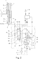
- FIG. 1 is a schematic structure of a lifting device 1 of a truck, not shown in the prior art shown.
- the lifting device 1 consists of a mast 2, on which a load-receiving means 3 is arranged raised and lowered.
- the load-receiving means 3 consists in the illustrated embodiment of a vertically movable in the mast 2 lifting 4, on which, for example, a load fork 5 formed by forks is attached as an attachment.
- a hydraulic lifting cylinder device 11 For lifting and lowering the load receiving means 3, a hydraulic lifting cylinder device 11 is provided.
- the mast consists of a stationary mast 2a and a raised to the stationary mast 2a and lowered extendable mast 2b, on which the load-receiving means 3 is arranged raised and lowered.
- the lifting cylinder device 11 serves to raise and lower the extension mast 2b relative to the stationary mast 2a.
- a flexible traction means 6, for example a lifting chain is provided, which is fastened with a first end to the lifting carriage 4.
- the traction means 6 is guided over a deflection roller 7 at the upper end of the extension mast 2b and secured with a second end to the stationary mast 2a.
- the lifting cylinder device 11 can be actuated by means of a control valve device 12 for raising and lowering the load-receiving means 3.
- the control valve device 12 is formed in the illustrated embodiment as throttling in intermediate positions proportional valve 13 with a designed as a neutral position blocking position 13a, a lifting position 13b and a lowered position 13c.
- the proportional valve 13 is connected to a delivery line 14 of a pump 15, which draws pressure medium from a container 17 by means of a suction line 16, to a container line 18 guided to the container 17 and to a pressure medium line 19 guided to the lifting cylinder device 11.
- the blocking position 13a of the control valve device 12 the connection of the pressure medium line 19 to the delivery line 14 and the container line 18 is shut off.
- the delivery line 14 is connected to the pressure medium line 19.
- the pressure medium line 19 communicates with the container line 18 in connection.
- the control valve device 12 is electrically actuated.
- an electrical actuating device 20a is provided, in the control of which the control valve device 12 is actuated in the direction of the lowering position 13c.
- a further electrical actuating device 20b the control valve device 12 can be actuated in the direction of the lifting position 13b.
- the actuators 20a, 20b are formed, for example, as a magnet, in particular a proportional magnet.
- an electronic control device 25 is provided which is in communication with the actuating devices 20a, 20b.
- control valve device 12 By means of a spring device formed by two springs 24a, 24b, the control valve device 12 is operated in the non-driven and de-energized state in the form of a neutral position blocking position 13a.
- the electronic control device 25 is on the input side with an operable by an operator control element 26 in conjunction, for example, a joystick, by the actuation of a lifting operation or a lowering operation of the lifting device 3 can be initiated and in lift mode, a lifting speed and lowering a sink speed can be specified.
- an operator control element 26 in conjunction, for example, a joystick, by the actuation of a lifting operation or a lowering operation of the lifting device 3 can be initiated and in lift mode, a lifting speed and lowering a sink speed can be specified.
- a flow control valve 30 is arranged in the container line 18.
- the flow control valve 30 is designed as a throttling in intermediate positions proportional valve with a flow position 30a and a blocking position 30b.
- the downflow control valve 30 is actuated by a spring 31 and in the container line 18 between the control valve device 12 and the downflow control valve 30 pending pressure in the direction of the flow position 30a.
- a corresponding control line 32 is guided from the container line 18 to a control pressure surface of the outflow control valve 30 which acts in the direction of the flow position 30a.
- a throttle 33 is arranged.
- the flow control valve 30 is actuated by the pressure in the pressure medium line 19 in the direction of the blocking position 30b.
- a corresponding control line 34 is guided by the pressure medium line 19 to a control pressure surface of the outflow control valve 30 which acts in the direction of the blocking position 30b.
- a throttle 35 is arranged.
- control valve device 12 and the downflow control valve 30 are arranged in a control valve block 40.
- the control valve device 12 For lifting the load-receiving means 3, the control valve device 12 is actuated in the lifting position 13b, so that sucked by the pump 15 pressure fluid from the container 17 by means of the suction line 16 and conveyed into the delivery line 14 to the control valve device 12. In the lifting position 13b, the control valve device 12 connects the delivery line 14 with the pressure medium line 19, so that the pump 15 delivers pressure medium to the lifting cylinder device 11.
- control valve device 12 is actuated in the lowered position 13c. Pressure medium thus flows from the lifting cylinder device 11 via the pressure medium line 19 into the container line 18 and to the outflow control valve 30.
- the flow control valve 30 limits the flow from the lifting cylinder 11 to the tank 17 flowing maximum volume flow load independent to a fixed value.
- the downflow control valve 30 is in this case set such that a maximum permissible sink speed of the load receiving means 3 of 0.6 m / s is maintained. Smaller lowering speeds are called by the Proportional valve 13 formed control valve means 12 controlled by varying the lowering position 13c.
- FIG. 2 is a schematic structure of a first embodiment of the lifting device 1 of a truck according to the invention, not shown. Same components with the FIG. 1 are hereby provided with the same reference numerals.
- a switching valve 45 is disposed between the control valve device 12 and the flow control valve 30, which activates the arranged in the container line 18 downflow control valve 30 in a first switching position 45a, so that in the sink operation of Hubzylinder owned 11 of the pressure medium flow through the arranged in the container line 18 Outflow control valve 30 flows from the lifting cylinder device 11 to the container 17, and deactivated in a second switching position 45b disposed in the container line 18 spatialstromregelventil 30, so that in the sink operation of Hubzylinder adopted 11 of the pressure medium flow bypassing arranged in the container line 18 downflow control valve 30 of the Hubzylinder learned 11th flows to the container 17.
- the switching valve 45 thus arranged in the container line 18 downflow control valve 45 can be switched on in the first switching position 45a and switched off in the second switching position 45b.
- the switching valve 45 is designed as a three-port two-position valve, which is connected with a first port A1 to the communicating with the control valve device 12 portion of the tank line 18, at a second port A2 to the associated with the flow control valve 30 portion of the tank line 18th is connected and connected to a third port A3 to a guided to the container 17 drain line 46.
- the drain line 46 forms a bypass line, which bypasses the arranged in the container line 18 downflow control valve 30.
- the switching valve 45 connects the first port A1 to the second port A2 and blocks the third port A3.
- the switching valve 45 connects in the second Switching position 45b the first port A1 with the third port A3 and blocks the second port A2.
- the switching valve 45 is electrically actuated and is for driving with the electronic control device 25 in connection.
- the switching valve 45 is in the illustrated embodiment of a spring means 47 in the first switching position 45a actuated and by means of an electric actuator 48, in particular a solenoid, which is in operative connection with the electronic control device 25, actuated in the second switching position 45b.
- the electronic control device 25 is connected to a sensor device 50 which detects the lowering speed of the load-receiving means 3.
- the sensor device 50 is designed as a lifting height sensor 51, with which the lifting height of the load-receiving means 3 can be measured.
- the lifting height sensor 51 is formed in the illustrated embodiment as a rope length sensor 52 which comprises a fixed to the stationary mast 2a housing and connected to the load receiving means 3 cable means 53.
- the lowering speed of the load receiving means 3 is calculated in the electronic control device 25 by a time derivation.
- the electronic control device 25 also outputs corresponding control commands to the control valve device 12 and the switching valve 45.
- the electronic control device 25 is designed such that in the lowering operation of the load receiving means 3, the electronic control device 25 in normal operation at functioning sensor device 50, the switching valve 45 is actuated in the second switching position 45b and actuates the switching valve 45 in the first switching position 45a in case of failure of the sensor device.
- a fault of the sensor device 50 is present, for example, in the event of failure of the sensor device 50 or if the sensor device 50 does not deliver a plausible signal.
- the switching valve 45 connects in the first position 45a, which represents the de-energized basic position, in the lowering operation of the load receiving means 3 coming from the control valve means 12 pressure medium flow with the flow control valve 30, so that the maximum lowering speed to the value set on the flow control valve 30, for example, from 0 , 6m / s, is complied with.
- the first position 45a of the switching valve 45 thus the maximum lowering speed of the load receiving means 3 is analogous to the FIG. 1 limited to the set value of the flow control valve 30.
- the switching valve 45 is by energizing the actuator 48 of the electronic control device operated in the second switching position 45b.
- the pressure medium coming from the control valve device 12 located in the lowering position 13c flows via the drain line 46 and thus into the container 17, bypassing the outflow control valve 30 arranged in the container line 18.
- the downflow control valve 30 arranged in the container line 18 is therefore deactivated and switched off.
- the lowering speed of the load receiving means 3 is controlled or regulated solely by the position of the valve spool of the proportional valve 13 in the direction of the lowering position 13c.
- the proportional control valve 13 is controlled by the electronic control device 25, for example, such that the maximum permissible lowering speed of 0.6m / s, regardless of the load and the viscosity of the pressure medium is not exceeded, but best approximated.
- the switching valve 45 is not actuated by the electronic control device 25 and the switching valve 45 is actuated by the spring 47 into the first switching position 45a ,
- the pressure medium coming from the control valve device 12 located in the drain position 13c flows through the drain flow control valve 30 arranged in the tank line 18 arranged in the container line 18 downflow control valve 30 is thus activated and activated.
- the downflow control valve 30 is in this case set such that regardless of the load on the load receiving means 3 in each lifting stage of the mast 2, the maximum permissible lowering speed of the load receiving means 3 of 0.6m / s is maintained.
- the truck can thus continue to operate safely with a reduced lowering speed of the load receiving means 3 until repair of the sensor device 50 and in compliance with the maximum permissible lowering speed of the load receiving means 3 of 0.6 m / s.
- FIG. 2 makes it possible to make the best possible use of the maximum permissible lowering speed of the load receiving means 3 of 0.6 m / s in the case of a mast 2 with several lifting stages, as a result of which an increase in the handling capacity of the industrial truck can be achieved.
- Lower reliability requirements performance levels
- the truck can continue to operate in case of failure of the sensor device 50 and thus a failure of the electronic Senk Anthonyser charged of the load receiving means 3 with slight restrictions on the achievable maximum lowering speed to repair the sensor device 50, so that there is a high availability of the truck.
- FIG. 3 is a schematic structure of a second embodiment of the lifting device 1 of a truck according to the invention, not shown. Same components with the FIGS. 1 and 2 are hereby provided with the same reference numerals.
- a further flow control valve 60 is arranged in the drain line 46.
- the flow control valve 60 is designed as a throttling in intermediate positions proportional valve with a flow position 60a and a blocking position 60b.
- the downflow control valve 60 is actuated by a spring 61 and the pending in the drain line 46 between the switching valve 45 and the flow control valve 60 pressure in the direction of the flow position 60a.
- a corresponding control line 62 from the drain line 46 to one in the direction of Flow position 60a acting control pressure surface of the flow control valve 60 out.
- a throttle 63 is arranged in the control line 62.
- the flow control valve 60 is actuated by the pressure in the pressure medium line 19 in the direction of the blocking position 60b.
- a corresponding control line 64 is connected to the control line 34 of the outflow control valve 30 and guided by the control line 34 to a control pressure surface of the outflow control valve 60 acting in the direction of the blocking position 60b.
- the downflow control valve 30 in the tank line 18 is set to a first maximum sink rate, for example the value of 0.6 m / s, and the further downflow control valve 60 in the downcomer 46 is set to a second maximum sink rate, the second maximum sink rate being higher than the first maximum Lowering speed is.
- the electronic control device 25 is connected to a load on the load-receiving means 3 detecting sensor device 65 in connection.
- the sensor device 65 is formed in the illustrated embodiment as a pressure sensor 66 which detects the pressure in the pressure medium line 19.
- the sensor device 65 may be formed as an optical sensor which detects a load located on the load receiving means 3.
- the electronic control device 25 is configured such that in the lowering operation of the load receiving means 3, the electronic control device 25 actuates the switching valve 45 in the first switching position 45a at a load detected by the sensor device 65 and the switching valve 45 in the second in no detected by the sensor direction 65 load Switching position 45b actuated.
- the electronic control device actuates the switching valve 45 in the first switching position 45a.
- the switching valve 45 connects in the first position 45 a, which represents the de-energized basic position, in the lowering operation of the load receiving means 3 coming from the control valve means 12 pressure medium flow with the in the Container line 18 arranged outflow control valve 30, which is set to the lower maximum lowering speed.
- the switching valve 45 is actuated into the first switching position 45a when a load on the load receiving means 3 and thus the operating state sinks "with load” is detected by the sensor device 65 and if there is a fault of the sensor device 65, for example the sensor device 65 has failed or not provides plausible signal.
- the pressure medium coming from the control valve device 12 located in the lowering position 13c flows through the flow control valve 30 arranged in the container line 18, which in each lifting step of the mast 2, the maximum permissible lowering speed of the lifting device 3 to the value of 0.6m / s limited.
- the switching valve 45 is actuated by the electronic control device 25 by energizing the actuating device 48 into the second switching position 45b.
- the pressure medium coming from the control valve device 12 located in the lowering position 13 c flows into the container 17 via the drain line 46 and via the further outflow control valve 60, which is set to a higher maximum lowering speed, so that a higher maximum lowering speed of the empty lifting device 3 can be achieved with a maximum lowering speed above 0.6 m / s.
- the execution of FIG. 3 allows switching with the switching valve 45 between two flow control valves 30, 60, the downflow control valve 30 is set to a maximum allowable lowering speed of the load receiving means 3 with load and the downflow control valve 60 to a maximum allowable lowering speed of the load receiving means 3 without load.
- the switching of the switching valve 45 takes place as a function of the load detection by the sensor device 65. In the event of failure of the load detection, the lower maximum permissible lowering speed is selected.
- the maximum permissible lowering speed of the load handling device can be increased for the no-load operating condition from the limit of 0.6 m / s, which increases the handling capacity of the truck.
- the truck can continue to operate in case of failure of the sensor device 65 and thus a failure of the load detection with little restrictions in the achievable maxialmen lowering speed until the repair of the sensor device 65, so that there is a high availability of the truck.
- FIG. 4 is a schematic structure of a third embodiment of the lifting device 1 of a truck according to the invention, not shown. Same components with the FIGS. 1 to 3 are hereby provided with the same reference numerals.
- the mast 2 of FIG. 4 has at least two lifting stages.
- a hydraulic lifting cylinder device 11a is provided for lifting and lowering the load-receiving means 3 relative to the extension mast 2b.
- the lifting cylinder device 11a forms a first lifting stage (free lift).
- the flexible traction means 6, for example a lifting chain provided in the FIG. 4 is fixed at a first end to the lifting carriage 4, is guided via a guide roller 7 on the extendable piston rod of the lifting cylinder device 11a and is attached with a second end to the extension mast 2b.
- the hydraulic lifting cylinder device 11b serves to raise and lower the extension mast 2b relative to the stationary mast 2a.
- the lifting cylinder device 11b forms a second lifting stage (mast lift).
- the lifting cylinder device 11a is connected to the lifting cylinder device 11b by means of a pressure medium line 75.
- each lifting step one of the lifting stage associated flow control valve 30, 60 is provided.
- the arranged in the container line 18 downflow control valve 30 is in this case the first stroke (free lift) associated with and arranged in the drain line 46 downflow control valve 60 of the second lifting stage (mast lift).
- the electronic control device 25 is connected to a sensor device 70 which detects the lifting stages.
- the sensor device 70 is formed in the illustrated embodiment as a pressure sensor 66 which detects the pressure in the pressure medium line 19. Since the two lifting cylinder devices 11a, 11b have different cross-sectional areas, the respective lifting step can be detected via the pressure sensor 66.
- the sensor device 70 may be formed as one or more switches 71.
- the electronic control device 25 is configured in such a way that the electronic control device 25 actuates the switching valve 45 in the second switching position 45b when the second lifting step (mast lift) is detected by the sensor device 70 and at a first lifting step (free stroke detected by the sensor device 70) in the lowering operation of the load receiving means 3 ) the switching valve 45 is operated in the first switching position 45a.
- the first stroke forms in the mast 2 of FIG. 4 the fastest lowering lowering step.
- the downflow control valve 30 in the container line 18 is thus assigned to the fastest lowering lifting stage (free lift) and limits the maximum lowering speed of this lifting stage (free lift), for example to the value of 0.6 m / s.
- the further outflow control valve 60 in the drain line 46 is assigned to the slower lowering lifting stage (mast lift) and limits the maximum lowering speed of this lifting stage (mast lift), for example, also to the value of 0.6 m / s.
- the electronic control device 25 actuates the switching valve 45 in the first switching position 45a in the event of a fault of the sensor device.
- FIG. 4 makes it possible to make the best possible use of the maximum permissible lowering speed of the load receiving means 3 of 0.6 m / s in the case of a mast 2 with several lifting stages, as a result of which an increase in the handling capacity of the industrial truck can be achieved.
- Lower reliability requirements performance levels
- the truck can continue to operate in case of failure of the sensor device 70 and thus a failure of the Hubménerkennung with little restrictions on the achievable maximum lowering speed until the repair of the sensor device 70, so that there is a high availability of the truck.
- control valve device 12 may be actuated electro-hydraulically, wherein the actuators 20a, 20b actuate electrically controllable pilot valves, with which the control valve device 12 in the lowered position 13c and the lifting position 13b actuating control pressure is generated.
- control valve device 12 with separate control valves for lifting and lowering operation is possible.
Landscapes
- Engineering & Computer Science (AREA)
- Structural Engineering (AREA)
- Mechanical Engineering (AREA)
- Transportation (AREA)
- Fluid Mechanics (AREA)
- General Engineering & Computer Science (AREA)
- Chemical & Material Sciences (AREA)
- Combustion & Propulsion (AREA)
- Civil Engineering (AREA)
- Physics & Mathematics (AREA)
- Life Sciences & Earth Sciences (AREA)
- Geology (AREA)
- Forklifts And Lifting Vehicles (AREA)
Abstract
Description
- Die Erfindung betrifft ein Flurförderzeug mit einer Hubvorrichtung, die ein an einem Hubgerüst anhebbar und absenkbar angeordnetes Lastaufnahmemittel aufweist, wobei zum Heben und Senken des Lastaufnahmemittels eine hydraulische Hubzylindereinrichtung vorgesehen ist, die mittels einer Steuerventileinrichtung betätigbar ist, wobei die Steuerventileinrichtung an eine zu der Hubzylindereinrichtung geführte Druckmittelleitung und an eine zu einem Behälter geführte Behälterleitung angeschlossen ist und wobei die Steuerventileinrichtung eine Senkenstellung aufweist, in der die Druckmittelleitung mit der Behälterleitung verbunden ist, wobei in der Behälterleitung ein Ablaufstromregelventil (Ablaufvolumenstromregelventil) angeordnet ist.
- Flurförderzeuge sind zur Handhabung von Lasten mit einem Lastaufnahmemittel versehen, das in der Regel von einem am Hubgerüst anhebbaren und absenkbaren Hubschlitten und einem daran befestigten Anbaugerät gebildet ist. Das Anbaugerät kann beispielsweise als eine von Gabelzinken bestehende Lastgabel ausgebildet werden, mittels der eine Last, beispielsweise eine Palette unterfahren werden kann.
- Bei Flurförderzeugen, bei denen das Lastaufnahmemittel mittels einer hydraulischen Hubzylindereinrichtung anhebbar und absenkbar ist, bestimmt die Auslenkung der Steuerventileinrichtung im Senkenbetrieb die Senkengeschwindigkeit des Lastaufnahmemittels. Aus Sicherheitsgründen ist ein gesetzlich vorgeschriebener Grenzwert von 0,6 m/s für eine maximale Senkengeschwindigkeit des Lastaufnahmemittels bzw. einer Last vorgeschrieben. Um diesen gesetzlich vorgeschriebenen Grenzwert einzuhalten, wird bei gattungsgemäßen Hubvorrichtungen die Steuerventileinrichtung derart ausgelegt, dass bei vollständig in eine Senkenstellung betätigter Steuerventileinrichtung in allen Betriebsbedingungen ein maximaler Druckmittelablaufstrom von der Hubzylindereinrichtung zu einem Behälter abströmen kann. Um die Einhaltung des gesetzlich vorgeschriebenen Grenzwertes für die maximale Senkengeschwindigkeit von 0,6 m/s sicherzustellen, ist bei gattungsgemäßen Flurförderzeugen, in einer Behälterleitung, die von der Steuerventileinrichtung zu einem Behälter führt und in der in der Senkenstellung der Steuerventileinrichtung Druckmittel von der Hubzylindereinrichtung zum Behälter abströmt, ein Ablaufstromregelventil vorgesehen. Das in der Behälterleitung angeordnete Ablaufstromregelventil begrenzt unabhängig vom Lastdruck einer auf dem Lastaufnahmemittel befindlichen Last den maximalen Volumenstrom in der Behälterleitung im Senkenbetrieb der Hubvorrichtung und somit die Senkengeschwindigkeit der Last auf den Grenzwert von 0,6 m/s. Das Ablaufstromregelventil wird hierbei derart eingestellt, dass es im Senkenbetrieb die am schnellsten senkende Hubstufe des Hubgerüstes mit seiner maximalen Einstelltoleranz auf den Grenzwert von 0,6m/s beschränkt. Diese Einstellung des Ablaufstromregelventils bedingt, dass weitere Hubstufen des Hubgerüsts unter Umständen deutlich langsamer eine Last absenken. In der Praxis ergibt sich bei gattungsgemäßen Flurförderzeugen mit einem Ablaufstromregelventil, dass im Senkenbetrieb der Hubvorrichtung eine Last mit einer Geschwindigkeit zwischen 0,5 m/s und 0,56 m/s abgesenkt wird.
- Bei Flurförderzeugen, beispielsweise Schubmaststaplern, mit Hubhöhen des Lastaufnahmemittels von 13-15 m wirkt sich das Nicht-Ausnutzen der maximal zulässigen Senkengeschwindigkeit von 0,6m/s nachteilig auf die Umschlagsleistung des Flurförderzeugs auf.
- Aus der
DE 10 2012 101 949 A1 ist eine Hubvorrichtung eines Flurförderzeugs bekannt, die ohne Ablaufstromregelventil auskommt und bei der mit Hilfe einer elektronischen Erfassung der Senkengeschwindigkeit des Lastaufnahmemittels die Steuerventileinrichtung derart geregelt angesteuert wird, dass die maximal zulässige Senkengeschwindigkeit von 0,6m/s im Senkenbetrieb des Lastaufnahmemittels eingehalten wird. Dies erfordert jedoch, dass die Senkengeschwindigkeit des Lastaufnahmemittels mit einem entsprechenden System, beispielsweise mittels einer Sensoreinrichtung, sehr zuverlässig erfasst werden muss, da bei einem Ausfall einer oder mehreren Komponenten, die die Senkengeschwindigkeit des Lastaufnahmemittels erfassen, die Einhaltung des Grenzwertes von 0,6 m/s für die maximal zulässige Senkengeschwindigkeit nicht mehr gewährleistet ist und in Folge dessen, das Flurförderzeug bis zu einer Instandhaltung stillgelegt werden muss. Ein sehr zuverlässiges System für die Erfassung der Senkengeschwindigkeit des Lastaufnahmemittels führt jedoch zu einem hohen Bauaufwand mit entsprechenden hohen Kosten für die die Senkengeschwindigkeit des Lastaufnahmemittels erfassenden Komponenten oder erfordert, dass diese Komponente gegebenenfalls redundant vorgesehen werden müssen. - Der vorliegenden Erfindung liegt die Aufgabe zugrunde, ein Flurförderzeug der eingangs genannten Gattung zur Verfügung zu stellen, das mit einer geringen Zuverlässigkeit einer Sensoreinrichtung auskommt und im Fehlerfall der Sensoreinrichtung einen Weiterbetrieb des Flurförderzeugs unter Einhaltung des Grenzwertes von 0,6 m/s für die maximal zulässige Senkengeschwindigkeit ermöglicht.
- Diese Aufgabe wird erfindungsgemäß dadurch gelöst, dass in der Behälterleitung zwischen der Steuerventileinrichtung und dem Ablaufstromregelventil ein Schaltventil angeordnet ist, das in einer ersten Schaltstellung das in der Behälterleitung angeordnete Ablaufstromregelventil aktiviert, so dass im Senkenbetrieb der Hubzylindereinrichtung der Druckmittelstrom über das in der Behälterleitung angeordnete Ablaufstromregelventil von der Hubzylindereinrichtung zum Behälter abströmt, und das in einer zweiten Schaltstellung das in der Behälterleitung angeordnete Ablaufstromregelventil deaktiviert, so dass im Senkenbetrieb der Hubzylindereinrichtung der Druckmittelstrom unter Umgehung des in der Behälterleitung angeordneten Ablaufstromregelventils von der Hubzylindereinrichtung zum Behälter abströmt.
- Erfindungsgemäß ist somit in der Behälterleitung ein Schaltventil vorgesehen, das es ermöglicht, das in der Behälterleitung angeordnete Ablaufstromregeventil zuzuschalten und somit zu aktiveren und wegzuschalten und somit zu deaktivieren. Ist das Ablaufstromregeventil deaktiviert, strömt im Senkenbetrieb der Hubzylindereinrichtung der Druckmittelstrom unter Umgehung des in der Behälterleitung angeordneten Ablaufstromregelventils von der Hubzylindereinrichtung zum Behälter ab, so dass eine hohe Senkengeschwindigkeit auch gegebenenfalls oberhalb des Grenzwertes von 0,6m/s erzielbar ist, wodurch eine hohe Umschlagsleistung des Flurförderzeugs erzielbar ist. Im Fehlerfall einer Sensoreinrichtung, beispielsweise der Erfassung der Senkengeschwindigkeit des Lastaufnahmemittels, kann das Ablaufstromregelventil aktiviert werden, so dass im Senkenbetrieb der Hubzylindereinrichtung der Druckmittelstrom über das in der Behälterleitung angeordnete Ablaufstromregelventil von der Hubzylindereinrichtung zum Behälter abströmt und das Ablaufstromregelventil in der Behälterleitung die Einhaltung der maximalen Senkengeschwindigkeit auf den Grenzwert von 0,6m/s sicherstellt. Dadurch kann die Sensoreinrichtung, beispielsweise eine Erfassung der Senkengeschwindigkeit des Lastaufnahmemittels, mit einer verringerten Zuverlässigkeit ausgeführt werden und im Fehlerfall der Sensoreinrichtung wird ein Weiterbetrieb des Flurförderzeugs unter Einhaltung des Grenzwertes von 0,6 m/s für die maximal zulässige Senkengeschwindigkeit des Lastaufnahmemittels ermöglicht, beispielsweise bis zur Instandsetzung der Sensoreinrichtung.
- Gemäß einer vorteilhaften Ausführungsform der Erfindung ist das Schaltventil als Dreianschluss-Zweistellungsventil ausgebildet, das mit einem ersten Anschluss an den mit der Steuerventileinrichtung in Verbindung stehenden Abschnitt der Behälterleitung angeschlossen ist, an einem zweiten Anschluss an den mit dem Ablaufstromregelventil in Verbindung stehenden Abschnitt der Behälterleitung angeschlossen ist und an einem dritten Anschluss an eine zu dem Behälter geführte Ablaufleitung angeschlossen ist, wobei das Schaltventil in der ersten Schaltstellung den ersten Anschluss mit dem zweiten Anschluss verbindet und der dritte Anschluss abgesperrt ist und wobei das Schaltventil in der zweiten Schaltstellung den ersten Anschluss mit dem dritten Anschluss verbindet und der zweite Anschluss abgesperrt ist. Mit einem derartigen Schaltventil kann auf einfache Weise und mit geringem Zusatzaufwand das in der Behälterleitung angeordnete Ablaufstromregelventil in der ersten Schaltstellung des Schaltventils aktiviert und somit zugeschalten werden und in der zweiten Schaltstellung des Schaltventils deaktiviert und somit weggeschalten werden.
- Gemäß einer vorteilhaften Ausgestaltungsform der Erfindung ist das Schaltventil mittels einer elektronischen Steuereinrichtung betätigt. Mit einem elektrisch betätigten Schaltventil, das zur Betätigung und Ansteuerung mit einer elektronischen Steuereinrichtung in Verbindung steht, kann auf einfache Weise und mit geringem Zusatzaufwand das in der Behälterleitung angeordnete Ablaufstromregelventil in der ersten Schaltstellung des Schaltventils aktiviert und somit zugeschalten und in der zweiten Schaltstellung des Schaltventils deaktiviert und somit wegeschalten werden.
- Das Schaltventil ist gemäß einer vorteilhaften Ausführungsform der Erfindung von einer Federeinrichtung in die erste Schaltstellung betätigbar und mittels einer elektrischen Betätigungseinrichtung, insbesondere einem Schaltmagnet, die mit der elektronischen Steuereinrichtung in Wirkverbindung steht, in die zweite Schaltstellung betätigbar. Hierdurch ergibt sich eine hohe Betriebssicherheit, da bei nicht angesteuertem Schaltventil das Schaltventil von der Federeinrichtung in die erste Schaltstellung betätigt ist, in der das in der Behälterleitung angeordnete Ablaufstromregelventil aktiviert und somit zugeschalten ist und die Einhaltung der maximalen Senkengeschwindigkeit des Lastaufnahmemittels auf den Grenzwert von 0,6m/s sichergestellt ist.
- Die Steuerventileinrichtung ist zweckmäßigerweise als Proportionalventil ausgebildet, das von der elektronischen Steuereinrichtung betätigt ist. Dadurch kann auf einfache Weise die Senkengeschwindigkeit des Lastaufnahmemittels im Senkenbetrieb von der elektronischen Steuereinrichtung durch entsprechende Ansteuerung des Proportionalventils vorgegeben werden.
- Gemäß einer vorteilhaften Ausführungsform der Erfindung steht die elektronische Steuereinrichtung mit einer die Senkengeschwindigkeit des Lastaufnahmemittels erfassenden Sensoreinrichtung in Verbindung, wobei die elektronische Steuereinrichtung derart ausgebildet ist, dass im Senkenbetrieb des Lastaufnahmemittels die elektronische Steuereinrichtung im Normalbetrieb bei funktionsfähiger Sensoreinrichtung das Schaltventil in die zweite Schaltstellung betätigt und im Fehlerfall der Sensoreinrichtung das Schaltventil in die erste Schaltstellung betätigt. Hierdurch wird auf einfache Weise ermöglicht, dass im Normalbetrieb bei funktionsfähiger Sensoreinrichtung das Schaltventil in die zweite Schaltstellung betätigt werden kann und das in der Behälterleitung angeordnete Ablaufstromregelventil deaktiviert und somit weggeschalten werden kann. Im Senkenbetrieb der Hubzylindereinrichtung strömt somit der Druckmittelstrom unter Umgehung des in der Behälterleitung angeordneten Ablaufstromregelventils von der Hubzylindereinrichtung zum Behälter ab. Die Regelung der Senkengeschwindigkeit des Lastaufnahmemittels erfolgt hierbei mittels der elektronischen Steuereinrichtung durch entsprechende Ansteuerung der als Proportionalventils ausgebildeten Steuerventileinrichtung in die Senkenstellung. Als Normalbetrieb bei funktionsfähiger Sensoreinrichtung ist hierbei ein Zustand zu verstehen, in dem die Erfassung der Senkengeschwindigkeit des Lastaufnahmemittels verfügbar ist bzw. ein plausibles Signal liefert. Im Fehlerfall der Sensoreinrichtung, wobei die Erfassung der Senkengeschwindigkeit des Lastaufnahmemittels ausgefallen ist bzw. ein unplausibles Signal liefert, wird das Schaltventil in die erste Schaltstellung betätigt werden und das in der Behälterleitung angeordnete Ablaufstromregelventil aktiviert und somit zugeschalten. Im Senkenbetrieb der Hubzylindereinrichtung strömt somit der Druckmittelstrom über das in der Behälterleitung angeordneten Ablaufstromregelventils von der Hubzylindereinrichtung zum Behälter ab, so dass das Ablaufstromregelventil in der Behälterleitung die Einhaltung des Grenzwertes von 0,6m/s für die maximale Senkengeschwindigkeit unabhängig von der Last sicherstellt. Das in der Behälterleitung angeordnete Ablaufstromregelventil ist hierzu vorzugsweise derart eingestellt, dass in keiner Hubstufe des Hubgerüstes die maximal erlaubte Senkengeschwindigkeit von 0,6m/s überschritten wird. Das Flurförderzeug kann somit im Fehlerfall der Sensoreinrichtung mit einer auf den Grenzwert von 0,6m/s begrenzten maximalen Senkengeschwindigkeit sicher bis zur Instandsetzung der Sensoreirichtung weiterbetrieben werden.
- Die die Senkengeschwindigkeit des Lastaufnahmemittels erfassende Sensoreinrichtung kann beispielsweise als Hubhöhensensor des Lastaufnahmemittels ausgebildet sein, wobei in der elektronischen Steuereinrichtung aus dem Hubhöhensignal des Hubhöhensensors die Senkengeschwindigkeit des Lastaufnahmemittels berechnet wird. Mit einem derartigen, beispielsweise als Längensensor ausgebildeten Hubhöhensensor wird die Entfernung des Lastaufnahmemittels relativ zur Fahrbahn oder zu dem Flurförderzeug gemessen. In der elektronischen Steuereinrichtung kann aus dem Längensignal des Hubhöhensensors auf einfache Weise durch eine zeitliche Ableitung die Senkengeschwindigkeit des Lastaufnahmemittels berechnet werden.
- Der Hubhöhensensor kann beispielswiese als Seillängensensor ausgebildet sein, der am Hubgerüst oder dem Fahrzeugkörper des Flurförderzeugs angeordnet ist und ein mit dem Lastaufnahmemittel verbundenes Seilmittel aufweist. Mit einem derartigen Hubhöhensensor kann auf einfache Weise die Hubhöhe zum Fahrzeugkörper des Flurförderzeugs gemessen werden und aus dem Hubhöhensignal in der elektronischen Steuereinrichtung die Senkengeschwindigkeit des Lastaufnahmemittels berechnet werden.
- Die die Senkengeschwindigkeit des Lastaufnahmemittels erfassende Sensoreinrichtung kann auch als Durchflussmesser ausgebildet sein. Mit einem derartigen Durchflussmesser kann auf einfache Weise in der elektronischen Steuereinrichtung die Senkengeschwindigkeit des Lastaufnahmemittels berechnet werden.
- Gemäß einer Ausführungsform der Erfindung ist in der Ablaufleitung ein weiteres Ablaufstromregelventil angeordnet. Dadurch wird es mit dem Schaltventil möglich, zwischen dem in der Behälterleitung angeordneten Ablaufstromregelventil und dem in der Ablaufleitung angeordneten weiteren Ablaufstromregelventil umzuschalten. Dadurch wird es ermöglicht, für bestimmte Betriebszustände, beispielsweise einen Senkenvorgang ohne Last, die maximal zulässige Senkengeschwindigkeit gegenüber dem Grenzwert von 0,6m/s zu erhöhen, in dem in derartigen Betriebszuständen das weitere Ablaufstromregelventil in der Ablaufleitung mittels des Umschaltventils aktiviert wird.
- Das Ablaufstromregelventil in der Behälterleitung ist hierbei gemäß einer vorteilhaften Ausgestaltungsform der Erfindung auf eine erste maximale Senkengeschwindigkeit eingestellt und das weitere Ablaufstromregelventil in der Ablaufleitung auf eine zweite maximale Senkengeschwindigkeit eingestellt, wobei die zweite maximale Senkengeschwindigkeit höher als die erste maximale Senkengeschwindigkeit ist. Sofern das in der Ablaufleitung angeordnete Ablaufstromregelventil derart eingestellt ist, dass im Senkenbetrieb der Grenzwert von 0,6m/s eingehalten wird, kann somit mit dem in der Ablaufleitung angeordneten weiteren Ablaufstromregelventil eine höhere Senkengeschwindigkeit in bestimmten Betriebszuständen erzielt werden.
- Gemäß einer vorteilhaften Ausführungsform der Erfindung steht hierzu die elektronische Steuereinrichtung mit einer eine Last auf dem Lastaufnahmemittel erfassenden Sensoreinrichtung in Verbindung, wobei die elektronische Steuereinrichtung derart ausgebildet ist, dass im Senkenbetrieb des Lastaufnahmemittels die elektronische Steuereinrichtung bei einer von der Sensoreinrichtung erfassten Last das Schaltventil in die erste Schaltstellung betätigt und bei keiner von der Sensorenrichtung erfassten Last das Schaltventil in die zweite Schaltstellung betätigt. Das in der Behälterleitung angeordnete Ablaufstromregelventil ist somit auf eine maximale Senkengeschwindigkeit für den Betriebszustand "mit Last" , beispielsweise den vorgeschriebenen Grenzwert von 0,6m/s, eingestellt und das in der Ablaufleitung angeordnete weitere Ablaufstromegelventil auf eine höhere maximale Senkengeschwindigkeit für den Betriebszustand "ohne Last" eingestellt. Hierdurch wird es auf einfache Weise ermöglicht, durch entsprechende Betätigung des Schaltventils beim Senken "ohne Last" mit einer gegenüber dem Grenzwert von 0,6m/s erhöhten maximalen Senkengeschwindigkeit das Lastaufnahmemittel abzusenken, wodurch eine Erhöhung der Umschlagsleistung des Flurförderzeugs erzielbar ist. Das Umschalten zwischen den beiden Ablaufstromregelventilen erfolgt in Abhängigkeit von einer Lasterkennung, die mittels der Sensoreinrichtung durchgeführt wird. Die Sensoreinrichtung, die eine Last auf dem Lastaufnahmemittel erfasst, kann beispielsweise als Drucksensor ausgebildet sein, der den Lastdruck in der von der Steuerventileinrichtung zu der Hubzylindereinrichtung führenden Druckmittelleitung erfasst. Alternativ kann die Sensoreinrichtung, die eine Last auf dem Lastaufnahmemittel erfasst, als optischer Sensor oder als eine von dem Fahrer zu betätigender Freigabeschalter sein.
- Um bei einem Ausfall der Sensoreinrichtung einen sicheren Weiterbetrieb des Flurförderzeugs zu ermöglichen, betätigt vorteilhafterweise die elektronische Steuereinrichtung im Fehlerfall der die Last erfassenden Sensoreinrichtung das Schaltventil in die erste Schaltstellung. Da in der ersten Schaltstellung der Senkenbetrieb über das in der Behälterleitung angeordnete Ablaufstromregelventil erfolgt, das auf die niedrigere maximale Senkengeschwindigkeit eingestellt ist, kann somit im Fehlerfall der Erfassung der Last auf dem Lastaufnahmemittels ein sicherer Weiterbetrieb des Flurförderzeugs unter Einhaltung des Grenzwertes von 0,6 m/s für die maximal zulässige Senkengeschwindigkeit des Lastaufnahmemittels erzielt werden, beispielsweise bis zur Instandsetzung der Lasterfassung.
- Gemäß einer Ausführungsform der Erfindung ist das Schaltventil in Abhängigkeit von der Betätigung einer von einem Fahrer des Flurförderzeugs betätigten Eingabevorrichtung betätigbar. Die Eingabevorrichtung kann beispielsweise von einem vom Fahrer zu betätigenden Schalter gebildet sein. Der Fahrer erhält somit über die Eingabevorrichtung bewusst die Möglichkeit, eine erhöhte Senkengeschwindigkeit zu wählen. Hierdurch wird es ebenfalls auf einfache Weise ermöglicht, durch entsprechende Betätigung des Schaltventils einerseits den Grenzwert von 0,6m/s für die Senkengeschwindigkeit einzuhalten oder andererseits mit einer erhöhten maximalen Senkengeschwindigkeit das Lastaufnahmemittel abzusenken, wodurch eine Erhöhung der Umschlagsleistung des Flurförderzeugs erzielbar ist. Das Umschalten des Schaltventils durch Betätigen der Eingabevorrichtung kann der Fahrer beispielsweise durchführen, um bewusst eine erhöhte maximalen Senkengeschwindigkeit das Lastaufnahmemittel zu wählen, wenn beispielsweise die aufgenommene Last unempfindlich ist oder die aufgenommene Last geklammert ist. Voraussetzung für die erhöhte maximale Senkengeschwindigkeit das Lastaufnahmemittel kann eine funktionierende Sensoreinrichtung sein, mit der die Senkengeschwindigkeit des Lastaufnahmemittels erfasst wird.
- Gemäß einer vorteilhaften Ausgestaltungsform der Erfindung weist das Hubgerüst mindestens zwei Hubstufen auf und ist für jede Hubstufe ein der Hubstufe zugeordnetes Ablaufstromregelventil vorgesehen, wobei das in der Behälterleitung angeordnete Ablaufstromregelventil der ersten Hubstufe zugeordnet ist und das in der Ablaufleitung angeordnete Ablaufstromregelventil der zweiten Hubstufe zugeordnet ist, wobei die elektronische Steuereinrichtung mit einer die Hubstufen erfassenden Sensoreinrichtung in Verbindung steht, wobei die elektronische Steuereinrichtung derart ausgebildet ist, dass im Senkenbetrieb des Lastaufnahmemittels die elektronische Steuereinrichtung bei von der Sensoreinrichtung erfassten zweiten Hubstufe das Schaltventil in die zweite Schaltstellung betätigt und bei einer von der Sensoreinrichtung erfassten ersten Hubstufe das Schaltventil in die erste Schaltstellung betätigt. Derartige Hubstufen können bei einem Hubgerüst von einem Freihub als erste Hubstufe und einem Masthub als zweite Hubstufe ausgebildet sein. Für jede Hubstufe des Hubgerüstes ist hierbei ein der entsprechenden Hubstufe zugeordneten Ablaufstromregelventil vorgesehen. Entsprechend der Anzahl der unterschiedlichen Hubstufen des Hubgerüstes ist somit eine Anzahl von Ablaufstromregelventilen vorgesehen. Die Ablaufstromregelventile sind jeweils derart eingestellt, dass sie die maximale Senkengeschwindigkeit der zugeordneten Hubstufe begrenzen, beispielsweis auf den Grenzwert von 0,6m/s. Mit der elektronischen Steuereinrichtung wird hierbei mittels der Sensoreinrichtung im Senkenbetrieb des Lastaufnahmemittels die Hubstufe erfasst, die gerade von dem Lastaufnahmemittel durchlaufen wird, und das der Hubstufe zugeordnete Ablaufstromregelventil durch entsprechende Ansteuerung des Schaltventils aktiviert, so dass jeweils das passende Ablaufstromregelventil zu der gerade aktiven Hubstufe geschaltet wird. Hierdurch ist ebenfalls eine Erhöhung der Umschlagsleistung des Flurförderzeugs erzielbar, da in jeder Hubstufe die maximal zulässige Senkengeschwindigkeit von 0,6m/s erzielbar ist. Die Sensoreinrichtung, mit der die Hubstufen des Hubgerüstes erfasst werden, kann beispielsweise von einem Schaltkontakt oder mehreren Schaltkontakten gebildet sein.
- Alternativ kann die Sensoreinrichtung, mit der die Hubstufen des Hubgerüstes erfasst werden, auch von einem Drucksensor gebildet sein, der den Lastdruck in der von der Steuerventileinrichtung zu der Hubzylindereinrichtung führenden Druckmittelleitung erfasst. Da für jede Hubstufe unterschiedliche Hubzylinder eingesetzt werden, unterscheiden sich bei gleicher Last auf dem Lastaufnahmemittel auch die Lastdrücke in den entsprechenden Hubstufen, so dass mit einem Drucksensor, der den Druck in der Druckmittelleitung erfasst, auch die gerade aktive Hubstufe erkannt werden kann.
- Gemäß einer vorteilhaften Ausführungsform der Erfindung ist das in der Behälterleitung angeordnete Ablaufstromregelventil der am schnellsten absenkenden Hubstufe zugeordnet und begrenzt die maximale Senkengeschwindigkeit dieser Hubstufe und ist das weitere Ablaufstromregelventil einer langsamer absenkenden Hubstufe zugeordnet und begrenzt die maximale Senkengeschwindigkeit dieser Hubstufe, wobei die elektronische Steuereinrichtung im Fehlerfall der Sensoreinrichtung das Schaltventil in die erste Schaltstellung betätigt. Die Ablaufstromregelventile begrenzen vorteilhafterweise die maximale Senkengeschwindigkeit der unterschiedlichen Hubstufen jeweils auf denselben Grenzwert von beispielswiese 0,6m/s. Die am schnellsten absenkende Hubstufe eines Hubgerüstes ist in der Regel der Freihub des Hubgerüstes und der Masthub bildet gegenüber dem Freihub eine langsamer absenkende Hubstufe. Sofern die elektronische Steuereinrichtung im Fehlerfall der Sensoreinrichtung, mit der die entsprechende Hubstufe erfasst werden kann, das Schaltventil in die erste Schaltstellung betätigt, kann eine hohe Betriebssicherheit erzielt werden und ein sicherer Weiterbetrieb des Flurförderzeugs unter Einhaltung des Grenzwertes von 0,6 m/s für die maximal zulässige Senkengeschwindigkeit des Lastaufnahmemittels erzielt werden, beispielsweise bis zur Instandsetzung der Hubstufenerfassung, da in der ersten Schaltstellung des Umschaltventils das in der Behälterleitung angeordnete Ablaufstromregelventil die maximale Senkengeschwindigkeit aller Hubstufen begrenzt und somit im Fehlerfall der Sensoreinrichtung auf die niedrigste Senkengeschwindigkeit geschaltet wird.
- Weitere Vorteile und Einzelheiten der Erfindung werden anhand der in den schematischen Figuren dargestellten Ausführungsbeispiele näher erläutert. Hierbei zeigt
- Figur 1
- den Schaltplan einer Hubvorrichtung eines Flurförderzeugs des Standes der Technik,
- Figur 2
- eine erste Ausführungsform eines Schaltplans einer Hubvorrichtung eines erfindungsgemäßen Flurförderzeugs,
- Figur 3
- eine zweite Ausführungsform eines Schaltplans einer Hubvorrichtung eines erfindungsgemäßen Flurförderzeugs und
- Figur 4
- eine dritte Ausführungsform eines Schaltplans einer Hubvorrichtung eines erfindungsgemäßen Flurförderzeugs.
- In der
Figur 1 ist ein schematischer Aufbau einer Hubvorrichtung 1 eines nicht näher dargestellten Flurförderzeugs des Standes der Technik dargestellt. - Die Hubvorrichtung 1 besteht aus einem Hubgerüst 2, an dem ein Lastaufnahmemittel 3 anhebbar und absenkbar angeordnet ist. Das Lastaufnahmemittel 3 besteht im dargestellten Ausführungsbeispiel aus einem im Hubgerüst 2 vertikal bewegbaren Hubschlitten 4, an dem beispielsweise eine von Gabelzinken gebildete Lastgabel 5 als Anbaugerät befestigt ist.
- Zum Anheben und Absenken des Lastaufnahmemittels 3 ist eine hydraulische Hubzylindereinrichtung 11 vorgesehen. Im dargestellten Ausführungsbeispiel besteht das Hubgerüst aus einem Standmast 2a und einem an dem Standmast 2a anhebbar und absenkbar angeordneten Ausfahrmast 2b, an dem das Lastaufnahmemittel 3 anhebbar und absenkbar angeordnet ist. Die Hubzylindereinrichtung 11 dient zum Anheben und Absenken des Ausfahrmastes 2b relativ zum Standmast 2a. Zum Anheben und Absenken des Lastaufnahmemittels 3 ist ein flexibles Zugmittel 6, beispielsweise einer Hubkette, vorgesehen, das mit einem ersten Ende an dem Hubschlitten 4 befestigt ist. Das Zugmittel 6 ist über eine Umlenkrolle 7 am oberen Ende des Ausfahrmastes 2b geführt und mit einem zweiten Ende an dem Standmast 2a befestigt.
- Die Hubzylindereinrichtung 11 ist mittels einer Steuerventileinrichtung 12 zum Anheben und Absenken des Lastaufnahmemittels 3 betätigbar. Die Steuerventileinrichtung 12 ist im dargestellten Ausführungsbeispiel als in Zwischenstellungen drosselndes Proportionalventil 13 mit einer als Neutralstellung ausgebildeten Sperrstellung 13a, einer Hebenstellung 13b und einer Senkenstellung 13c ausgebildet. Das Proportionalventil 13 ist hierzu an eine Förderleitung 14 einer Pumpe 15, die mittels einer Ansaugleitung 16 Druckmittel aus einem Behälter 17 ansaugt, an eine zu dem Behälter 17 geführte Behälterleitung 18 und an eine zu der Hubzylindereinrichtung 11 geführte Druckmittelleitung 19 angeschlossen. In der Sperrstellung 13a der Steuerventileinrichtung 12 ist die Verbindung der Druckmittelleitung 19 mit der Förderleitung 14 und der Behälterleitung 18 abgesperrt. In der Hebenstellung 13b der Steuerventileinrichtung 12 ist die Förderleitung 14 mit der Druckmittelleitung 19 verbunden. In der Senkenstellung 13c der Steuerventileinrichtung 12 steht die Druckmittelleitung 19 mit der Behälterleitung 18 in Verbindung.
- Die Steuerventileinrichtung 12 ist elektrisch betätigbar. Hierzu ist eine elektrische Betätigungseinrichtung 20a vorgesehen, bei deren Ansteuerung die Steuerventileinrichtung 12 in Richtung der Senkenstellung 13c betätigt wird. Mittels einer weiteren elektrischen Betätigungseinrichtung 20b ist die Steuerventileinrichtung 12 in Richtung der Hebenstellung 13b betätigbar. Die Betätigungseinrichtungen 20a, 20b sind beispielsweise als Magnet, insbesondere Proportionalmagnet, ausgebildet.
- Zur Ansteuerung der Steuerventileinrichtung 12 in die Hebenstellung 13b bzw. die Senkenstellung 13c ist eine elektronische Steuereinrichtung 25 vorgesehen, die mit den Betätigungseinrichtungen 20a, 20b in Verbindung steht.
- Mittels einer von zwei Federn 24a, 24b gebildeten Federeinrichtung ist die Steuerventileinrichtung 12 im nicht angesteuerten und stromlosen Zustand in die als Neutralstellung ausgebildete Sperrstellung 13a betätigt.
- Die elektronische Steuereinrichtung 25 steht eingangsseitig mit einem von einer Bedienperson betätigbaren Bedienelement 26 in Verbindung, beispielsweise einem Joystick, durch dessen Betätigung ein Hubvorgang bzw. ein Senkenvorgang des Lastaufnahmemittels 3 eingeleitet werden kann und im Hebenbetrieb eine Hebengeschwindigkeit sowie im Senkenbetrieb eine Senkengeschwindigkeit vorgegeben werden kann.
- In der Behälterleitung 18 ist ein Ablaufstromregelventil 30 angeordnet. Das Ablaufstromregelventil 30 ist als in Zwischenstellungen drosselndes Proportionalventil mit einer Durchflussstellung 30a und einer Sperrstellung 30b ausgebildet. Das Ablaufstromregelventil 30 ist von einer Feder 31 und dem in der Behälterleitung 18 zwischen der Steuerventileinrichtung 12 und der Ablaufstromregelventil 30 anstehenden Druck in Richtung der Durchflussstellung 30a betätigt. Hierzu ist eine entsprechende Steuerleitung 32 von der Behälterleitung 18 an eine in Richtung der Durchflussstellung 30a wirkende Steuerdruckfläche des Ablaufstromregelventils 30 geführt. In der Steuerleitung 32 ist eine Drossel 33 angeordnet. Das Ablaufstromregelventil 30 ist von dem in der Druckmittelleitung 19 anstehenden Druck in Richtung der Sperrstellung 30b betätigt. Hierzu ist eine entsprechende Steuerleitung 34 von der Druckmittelleitung 19 an eine in Richtung der Sperrstellung 30b wirkende Steuerdruckfläche des Ablaufstromregelventils 30 geführt. In der Steuerleitung 34 ist eine Drossel 35 angeordnet.
- Die Steuerventileinrichtung 12 und das Ablaufstromregelventil 30 sind in einem Steuerventilblock 40 angeordnet.
- Zum Anheben des Lastaufnahmemittels 3 wird die Steuerventileinrichtung 12 in die Hebenstellung 13b betätigt, so dass von der Pumpe 15 Druckmittel aus dem Behälter 17 mittels der Ansaugleitung 16 angesaugt und in die Förderleitung 14 zu der Steuerventileinrichtung 12 gefördert wird. Die Steuerventileinrichtung 12 verbindet in der Hebenstellung 13b die Förderleitung 14 mit der Druckmittelleitung 19, so dass die Pumpe 15 Druckmittel zu der Hubzylindereinrichtung 11 fördert.
- Zum Absenken des Lastaufnahmemittels 3 wird die Steuerventileinrichtung 12 in die Senkenstellung 13c betätigt. Druckmittel strömt somit aus der Hubzylindereinrichtung 11 über die Druckmittelleitung 19 in die Behälterleitung 18 und zu dem Ablaufstromregelventil 30.
- Das Ablaufstromregelventil 30 begrenzt den von der Hubzylindereinrichtung 11 zu dem Behälter 17 abströmenden maximalen Volumenstrom lastunabhängig auf einen fest eingestellten Wert. Das Ablaufstromregelventil 30 ist hierbei derart eingestellt, dass eine maximal zulässige Senkengeschwindigkeit des Lastaufnahmemittels 3 von 0,6m/s eingehalten wird. Kleinere Senkengeschwindigkeiten werden durch die als Proportionalventil 13 ausgebildete Steuerventileinrichtung 12 durch Variieren der Senkenstellung 13c gesteuert. Nach Durchströmen des Ablaufstromregelventils 30 gelangt im Senkenbetrieb des Lastaufnahmemittels 3 das aus der Hubzylindereinrichtung 11 abströmende Druckmittel in den Behälter 17.
- In der
Figur 2 ist ein schematischer Aufbau einer ersten Ausführungsform der Hubvorrichtung 1 eines nicht näher dargestellten erfindungsgemäßen Flurförderzeugs dargestellt. Gleiche Bauteile mit derFigur 1 sind hierbei mit gleichen Bezugsziffern versehen. - In der Behälterleitung 18 ist zwischen der Steuerventileinrichtung 12 und dem Ablaufstromregelventil 30 ein Schaltventil 45 angeordnet, das in einer ersten Schaltstellung 45a das in der Behälterleitung 18 angeordnete Ablaufstromregelventil 30 aktiviert, so dass im Senkenbetrieb der Hubzylindereinrichtung 11 der Druckmittelstrom über das in der Behälterleitung 18 angeordnete Ablaufstromregelventil 30 von der Hubzylindereinrichtung 11 zum Behälter 17 abströmt, und in einer zweiten Schaltstellung 45b das in der Behälterleitung 18 angeordnete Ablaufstromregelventil 30 deaktiviert, so dass im Senkenbetrieb der Hubzylindereinrichtung 11 der Druckmittelstrom unter Umgehung des in der Behälterleitung 18 angeordneten Ablaufstromregelventils 30 von der Hubzylindereinrichtung 11 zum Behälter 17 abströmt. Mit dem Schaltventil 45 kann somit das in der Behälterleitung 18 angeordnete Ablaufstromregelventil 45 in der ersten Schaltstellung 45a zugeschalten und in der zweiten Schaltstellung 45b weggeschalten werden.
- Das Schaltventil 45 ist als Dreianschluss-Zweistellungsventil ausgebildet, das mit einem ersten Anschluss A1 an den mit der Steuerventileinrichtung 12 in Verbindung stehenden Abschnitt der Behälterleitung 18 angeschlossen ist, an einem zweiten Anschluss A2 an den mit dem Ablaufstromregelventil 30 in Verbindung stehenden Abschnitt der Behälterleitung 18 angeschlossen ist und an einem dritten Anschluss A3 an eine zu dem Behälter 17 geführte Ablaufleitung 46 angeschlossen ist. Die Ablaufleitung 46 bildet eine Bypassleitung, die das in der Behälterleitung 18 angeordnete Ablaufstromregelventil 30 umgeht. Das Schaltventil 45 verbindet in der ersten Schaltstellung 45a den ersten Anschluss A1 mit dem zweiten Anschluss A2 und sperrt den dritten Anschluss A3 ab. Das Schaltventil 45 verbindet in der zweiten Schaltstellung 45b den ersten Anschluss A1 mit dem dritten Anschluss A3 und sperrt den zweiten Anschluss A2 ab.
- Das Schaltventil 45 ist elektrisch betätigbar und steht zur Ansteuerung mit der elektronischen Steuereinrichtung 25 in Verbindung.
- Das Schaltventil 45 ist im dargestellten Ausführungsbeispiel von einer Federeinrichtung 47 in die erste Schaltstellung 45a betätigbar ist und mittels einer elektrischen Betätigungseinrichtung 48, insbesondere einem Schaltmagnet, die mit der elektronischen Steuereinrichtung 25 in Wirkverbindung steht, in die zweite Schaltstellung 45b betätigbar.
- Die elektronische Steuereinrichtung 25 steht mit einer die Senkengeschwindigkeit des Lastaufnahmemittels 3 erfassenden Sensoreinrichtung 50 in Verbindung.
- Im dargestellten Ausführungsbeispiel ist die Sensoreinrichtung 50 als Hubhöhensensor 51 ausgebildet, mit dem die Hubhöhe des Lastaufnahmemittels 3 gemessen werden kann. Der Hubhöhensensor 51 ist im dargestellten Ausführungsbeispiel als Seillängensensor 52 ausgebildet, der ein an dem Standmast 2a befestigtes Gehäuse und ein mit dem Lastaufnahmemittel 3 verbundenes Seilmittel 53 umfasst.
- Aus dem von dem Hubhöhensensor 51 gelieferten Längensignal wird in der elektronischen Steuereinrichtung 25 durch eine zeitliche Ableitung die Senkengeschwindigkeit des Lastaufnahmemittels 3 berechnet. Die elektronische Steuereinrichtung 25 gibt weiterhin entsprechende Stellbefehle an die Steuerventileinrichtung 12 und das Schaltventil 45 aus.
- Die elektronische Steuereinrichtung 25 ist derart ausgebildet, dass im Senkenbetrieb des Lastaufnahmemittels 3 die elektronische Steuereinrichtung 25 im Normalbetrieb bei funktionsfähiger Sensoreinrichtung 50 das Schaltventil 45 in die zweite Schaltstellung 45b betätigt und im Fehlerfall der Sensoreinrichtung 50 das Schaltventil 45 in die erste Schaltstellung 45a betätigt. Ein Fehlerfall der Sensoreinrichtung 50 liegt beispielsweise bei einem Ausfall der Sensoreinrichtung 50 vor oder wenn die Sensoreinrichtung 50 kein plausibles Signal liefert.
- Das Schaltventil 45 verbindet in der ersten Stellung 45a, die die unbestromte Grundstellung darstellt, im Senkenbetrieb des Lastaufnahmemittels 3 den von der Steuerventileinrichtung 12 kommenden Druckmittelstrom mit dem Ablaufstromregelventil 30, so dass die maximale Senkengeschwindigkeit auf den an dem Ablaufstromregelventil 30 eingestellten Wert, beispielsweise von 0,6m/s, eingehalten wird. In der ersten Stellung 45a des Schaltventils 45 wird somit die maximale Senkengeschwindigkeit des Lastaufnahmemittels 3 analog zu der
Figur 1 auf den Einstellwert des Ablaufstromregelventils 30 begrenzt. - Sofern die Sensoreinrichtung 50 funktionsfähig ist und somit zur Verfügung steht und im Senkenbetrieb des Lastaufnahmemittels 3 im Normalbetrieb bei funktionsfähiger Sensoreinrichtung 50 die Sensoreinrichtung 50 ein plausibles Signal an die elektronische Steuereinrichtung 25 liefert, wird von der elektronischen Steuereinrichtung 25 das Schaltventil 45 durch Bestromen der Betätigungseinrichtung 48 in die zweite Schaltstellung 45b betätigt. In der zweiten Schaltstellung 45b strömt das von der in der Senkenstellung 13c befindlichen Steuerventileinrichtung 12 kommende Druckmittel über die Ablaufleitung 46 und somit unter Umgehung des in der Behälterleitung 18 angeordneten Ablaufstromregelventils 30 in den Behälter 17. Das in der Behälterleitung 18 angeordnete Ablaufstromregelventil 30 ist somit deaktiviert und weggeschaltet. Die Senkengeschwindigkeit des Lastaufnahmemittels 3 wird allein durch die Stellung des Ventilschiebers des Proportionalventils 13 in Richtung der Senkenstellung 13c gesteuert bzw. geregelt. In Abhängigkeit von der durch die Sensoreinrichtung 50 ermittelten Senkengeschwindigkeit des Lastaufnahmemittels 3 wird von der elektronischen Steuereinrichtung 25 das Proportionalventil 13 beispielsweise derart angesteuert, dass die maximal zulässige Senkengeschwindigkeit von 0,6m/s unabhängig von der Last und der Viskosität des Druckmittels nicht überschritten, aber bestmöglich angenähert wird.
- Sofern im Senkenbetrieb des Lastaufnahmemittels 3 ein Fehlerfall der Sensoreinrichtung 50 vorliegt, beispielsweise die Sensoreinrichtung 50 ausgefallen ist oder kein plausibles Signal liefert, wird von der elektronischen Steuereinrichtung 25 das Schaltventil 45 nicht angesteuert und das Schaltventil 45 von der Feder 47 in die erste Schaltstellung 45a betätigt. In der ersten Schaltstellung 45a durchströmt das von der in der Senkenstellung 13c befindlichen Steuerventileinrichtung 12 kommende Druckmittel das in der Behälterleitung 18 angeordnete Ablaufstromregelventil 30. Das in der Behälterleitung 18 angeordnete Ablaufstromregelventil 30 ist somit aktiviert und zugeschaltet. Das Ablaufstromregelventil 30 ist hierbei derart eingestellt, dass unabhängig von der auf dem Lastaufnahmemittel 3 befindlichen Last in jeder Hubstufe des Hubgerüstes 2 die maximal zulässige Senkengeschwindigkeit des Lastaufnahmemittels 3 von 0,6m/s eingehalten wird. Das Flurförderzeug kann somit mit einer reduzierten Senkengeschwindigkeit des Lastaufnahmemittels 3 bis zu einer Instandsetzung der Sensoreinrichtung 50 sicher und unter Einhaltung der maximal zulässigen Senkengeschwindigkeit des Lastaufnahmemittels 3 von 0,6m/s weiterbetrieben werden.
- Die Ausführung der
Figur 2 ermöglicht es, bei einem Hubgerüst 2 mit mehreren Hubstufen die maximal zulässige Senkengeschwindigkeit des Lastaufnahmemittels 3 von 0,6m/s bestmöglich auszunutzen, wodurch eine Erhöhung der Umschlagsleistung des Flurförderzeugs erzielbar ist. An die Sensoreinrichtung 50 können niedrigere Zuverlässigkeitsanforderungen (Performancelevel) gestellt werden, so dass sich ein geringerer Bauaufwand mit entsprechenden verringerten Kosten für die Sensoreinrichtung 50 ergibt. Das Flurförderzeug kann bei einem Ausfall der Sensoreinrichtung 50 und somit einem Ausfall der elektronischen Senkgeschwindigkeitserfassung des Lastaufnahmemittels 3 mit geringen Einschränkungen bei der erzielbaren maximalen Senkengeschwindigkeit bis zur Instandsetzung der Sensoreinrichtung 50 weiterbetrieben werden, so dass sich eine hohe Verfügbarkeit des Flurförderzeugs ergibt. - In der
Figur 3 ist ein schematischer Aufbau einer zweiten Ausführungsform der Hubvorrichtung 1 eines nicht näher dargestellten erfindungsgemäßen Flurförderzeugs dargestellt. Gleiche Bauteile mit denFiguren 1 und2 sind hierbei mit gleichen Bezugsziffern versehen. - In der
Figur 3 ist in der Ablaufleitung 46 ein weiteres Ablaufstromregelventil 60 angeordnet. Das Ablaufstromregelventil 60 ist als in Zwischenstellungen drosselndes Proportionalventil mit einer Durchflussstellung 60a und einer Sperrstellung 60b ausgebildet. Das Ablaufstromregelventil 60 ist von einer Feder 61 und dem in der Ablaufleitung 46 zwischen dem Schaltventil 45 und der Ablaufstromregelventil 60 anstehenden Druck in Richtung der Durchflusssstellung 60a betätigt. Hierzu ist eine entsprechende Steuerleitung 62 von der Ablaufleitung 46 an eine in Richtung der Durchflusssstellung 60a wirkende Steuerdruckfläche des Ablaufstromregelventils 60 geführt. In der Steuerleitung 62 ist eine Drossel 63 angeordnet. Das Ablaufstromregelventil 60 ist von dem in der Druckmittelleitung 19 anstehenden Druck in Richtung der Sperrstellung 60b betätigt. Hierzu ist eine entsprechende Steuerleitung 64 an die Steuerleitung 34 des Ablaufstromregelventils 30 angeschlossen und von der Steuerleitung 34 an eine in Richtung der Sperrstellung 60b wirkende Steuerdruckfläche des Ablaufstromregelventils 60 geführt. - Das Ablaufstromregelventil 30 in der Behälterleitung 18 auf eine erste maximale Senkengeschwindigkeit eingestellt, beispielsweise den Wert von 0,6m/s, und das weitere Ablaufstromregelventil 60 in der Ablaufleitung 46 auf eine zweite maximale Senkengeschwindigkeit eingestellt, wobei die zweite maximale Senkengeschwindigkeit höher als die erste maximale Senkengeschwindigkeit ist.
- Die elektronische Steuereinrichtung 25 steht mit einer eine Last auf dem Lastaufnahmemittel 3 erfassenden Sensoreinrichtung 65 in Verbindung. Die Sensoreinrichtung 65 ist im dargestellten Ausführungsbeispiel als Drucksensor 66 ausgebildet, der den Druck in der Druckmittelleitung 19 erfasst. Alternativ kann die Sensoreinrichtung 65 als optischer Sensor ausgebildet sein, der eine auf dem Lastaufnahmemittel 3 befindliche Last erkennt.
- Die elektronische Steuereinrichtung 25 ist derart ausgebildet, dass im Senkenbetrieb des Lastaufnahmemittels 3 die elektronische Steuereinrichtung 25 bei einer von der Sensoreinrichtung 65 erfassten Last das Schaltventil 45 in die erste Schaltstellung 45a betätigt und bei keiner von der Sensorenrichtung 65 erfassten Last das Schaltventil 45 in die zweite Schaltstellung 45b betätigt.
- Im Fehlerfall der Sensoreinrichtung 65, beispielsweise einem Ausfall der Sensoreinrichtung 65, betätigt die elektronische Steuereinrichtung das Schaltventil 45 in die erste Schaltstellung 45a.
- Das Schaltventil 45 verbindet in der ersten Stellung 45a, die die unbestromte Grundstellung darstellt, im Senkenbetrieb des Lastaufnahmemittels 3 den von der Steuerventileinrichtung 12 kommenden Druckmittelstrom mit dem in der Behälterleitung 18 angeordneten Ablaufstromregelventil 30, das auf die niedrigere maximale Senkengeschwindigkeit eingestellt ist.
- Das Schaltventil 45 wird in die erste Schaltstellung 45a betätigt, wenn mit der Sensoreinrichtung 65 eine Last auf dem Lastaufnahmemittel 3 und somit der Betriebszustand Senken "mit Last" erfasst wird sowie wenn ein Fehlerfall der Sensoreinrichtung 65 vorliegt, beispielsweise die Sensoreinrichtung 65 ausgefallen ist oder kein plausibles Signal liefert. In der ersten Schaltstellung 45a durchströmt das von der in der Senkenstellung 13c befindlichen Steuerventileinrichtung 12 kommende Druckmittel das in der Behälterleitung 18 angeordnete Ablaufstromregelventil 30, das in jeder Hubstufe des Hubgerüstes 2 die maximal zulässige Senkengeschwindigkeit des Lastaufnahmemittels 3 auf den Wert von 0,6m/s begrenzt.
- Wird mit der Sensoreinrichtung 65 keine Last auf dem Lastaufnahmemittel 3 und somit der Betriebszustand Senken "ohne Last" erfasst, wird von der elektronischen Steuereinrichtung 25 das Schaltventil 45 durch Bestromen der Betätigungseinrichtung 48 in die zweite Schaltstellung 45b betätigt. In der zweiten Schaltstellung 45b strömt das von der in der Senkenstellung 13c befindlichen Steuerventileinrichtung 12 kommende Druckmittel über die Ablaufleitung 46 und über das weitere Ablaufstromregelventil 60, das auf eine höhere maximale Senkengeschwindigkeit eingestellt ist, in den Behälter 17, so das eine höhere maximale Senkengeschwindigkeit des leeren Lastaufnahmemittels 3 mit einer maximalen Senkengeschwindigkeit oberhalb von 0,6m/s erzielt werden kann.
- Die Ausführung der
Figur 3 ermöglicht es, mit dem Schaltventil 45 zwischen zwei Ablaufstromregelventilen 30, 60 umzuschalten, wobei das Ablaufstromregelventil 30 auf eine maximal zulässige Senkengeschwindigkeit des Lastaufnahmemittels 3 mit Last und das Ablaufstromregelventil 60 auf eine maximal zulässige Senkengeschwindigkeit des Lastaufnahmemittels 3 ohne Last eingestellt ist. Das Umschalten des Schaltventils 45 erfolgt in Abhängigkeit von der Lasterkennung durch die Sensoreinrichtung 65. Bei einem Ausfall der Lasterkennung wird die niedrigere maximale zulässige Senkengeschwindigkeit gewählt. Mit der Ausführung derFigur 3 kann die maximal zulässige Senkengeschwindigkeit des Lastaufnahmemittels für den Betriebszustand ohne Last gegenüber dem Grenzwert von 0,6m/s erhöht werden, wodurch die Umschlagsleistung des Flurförderzeugs erhöht wird. An die Sensoreinrichtung 65 können niedrigere Zuverlässigkeitsanforderungen (Performancelevel) gestellt werden, so dass sich ein geringerer Bauaufwand mit entsprechenden verringerten Kosten für die Sensoreinrichtung 65 ergibt. Das Flurförderzeug kann bei einem Ausfall der Sensoreinrichtung 65 und somit einem Ausfall der Lasterkennung mit geringen Einschränkungen bei der erzielbaren maxialmen Senkengeschwindigkeit bis zur Instandsetzung der Sensoreinrichtung 65 weiterbetrieben werden, so dass sich eine hohe Verfügbarkeit des Flurförderzeugs ergibt. - In der
Figur 4 ist ein schematischer Aufbau einer dritten Ausführungsform der Hubvorrichtung 1 eines nicht näher dargestellten erfindungsgemäßen Flurförderzeugs dargestellt. Gleiche Bauteile mit denFiguren 1 bis 3 sind hierbei mit gleichen Bezugsziffern versehen. - Das Hubgerüst 2 der
Figur 4 weist mindestens zwei Hubstufen auf. Zum Anheben und Absenken des Lastaufnahmemittels 3 relativ zu dem Ausfahrmast 2b ist eine hydraulische Hubzylindereinrichtung 11a vorgesehen. Die Hubzylindereinrichtung 11a bildet eine erste Hubstufe (Freihub). Zum Anheben und Absenken des Lastaufnahmemittels 3 ist das flexibles Zugmittel 6, beispielsweise einer Hubkette, vorgesehen, das in derFigur 4 mit einem ersten Ende an dem Hubschlitten 4 befestigt ist, über eine Umlenkrolle 7 an der ausfahrbaren Kolbenstange der Hubzylindereinrichtung 11a geführt ist und mit einem zweiten Ende an dem Ausfahrmast 2b befestigt ist. Die hydraulische Hubzylindereinrichtung 11b dient zum Anheben und Absenken des Ausfahrmastes 2b relativ zum Standmast 2a. Die Hubzylindereinrichtung 11b bildet eine zweite Hubstufe (Masthub). Die Hubzylindereinrichtung 11a ist mit der Hubzylindereinrichtung 11b mittels einer Druckmittelleitung 75 verbunden. - In der
Figur 4 ist für jede Hubstufe ein der Hubstufe zugeordnetes Ablaufstromregelventil 30, 60 vorgesehen. Das in der Behälterleitung 18 angeordnete Ablaufstromregelventil 30 ist hierbei der ersten Hubstufe (Freihub) zugeordnet und das in der Ablaufleitung 46 angeordnete Ablaufstromregelventil 60 der zweiten Hubstufe (Masthub). - Die elektronische Steuereinrichtung 25 ist mit einer die Hubstufen erfassenden Sensoreinrichtung 70 in Verbindung. Die Sensoreinrichtung 70 ist im dargestellten Ausführungsbeispiel als Drucksensor 66 ausgebildet, der den Druck in der Druckmittelleitung 19 erfasst. Da die beiden Hubzylindereinrichtungen 11a, 11b unterschiedliche Querschnittsflächen aufweisen, kann über den Drucksensor 66 die jeweilige Hubstufe erfasst werden. Alternativ kann die Sensoreinrichtung 70 als ein oder mehrere Schalter 71 ausgebildet sein.
- Die elektronische Steuereinrichtung 25 ist derart ausgebildet, dass im Senkenbetrieb des Lastaufnahmemittels 3 die elektronische Steuereinrichtung 25 bei von der Sensoreinrichtung 70 erfassten zweiten Hubstufe (Masthub) das Schaltventil 45 in die zweite Schaltstellung 45b betätigt und bei einer von der Sensoreinrichtung 70 erfassten ersten Hubstufe (Freihub) das Schaltventil 45 in die erste Schaltstellung 45a betätigt.
- Die erste Hubstufe (Freihub) bildet bei dem Hubgerüst 2 der
Figur 4 die schnellste absenkende Hubstufe. - Das Ablaufstromregelventil 30 in der Behälterleitung 18 ist somit der am schnellsten absenkenden Hubstufe (Freihub) zugeordnet und begrenzt die maximale Senkengeschwindigkeit dieser Hubstufe (Freihub), beispielweise auf den Wert von 0,6m/s. Das weitere Ablaufstromregelventil 60 in der Ablaufleitung 46 ist der langsamer absenkenden Hubstufe (Masthub) zugeordnet und begrenzt die maximale Senkengeschwindigkeit dieser Hubstufe(Masthub), beispielweise ebenfalls auf den Wert von 0,6m/s. Die elektronische Steuereinrichtung 25 betätigt im Fehlerfall der Sensoreinrichtung 70 das Schaltventil 45 in die erste Schaltstellung 45a.
- In der
Figur 4 wird somit mit der Sensoreinrichtung 70 die jeweilige Hubstufe erfasst, die von dem Lastaufnahmemittel 3 im Senkenbetrieb gerade durchlaufen wird. Entsprechend der Anzahl der Hubstufen des Hubgerüstes 2 ist eine entsprechende Anzahl von Ablaufstromregelventilen 30, 60 vorgesehen, die jeweils derart eingestellt sind, dass diese die maximale Senkengeschwindigkeit der zugeordneten Hubstufe begrenzen. Von der elektronischen Steuereinrichtung 25 wird durch entsprechende Betätigung des Schaltventils 45 im Senkenbetrieb des Lastaufnahmemittels 3 das der aktiven Hubstufe zugeordnete Ablaufstromregelventil 30 bzw. 60 zugeschalten und aktiviert. Bei einem Ausfall der Sensoreinrichtung 70 zur Hubstufenerkennung wird durch entsprechende Ansteuerung des Schaltventils 45 auf das Ablaufstromregelventil 30 der am schnellsten senkenden Hubstufe und somit auf die niedrigste Senkengeschwindigkeit geschaltet. - Die Ausführung der
Figur 4 ermöglicht es, bei einem Hubgerüst 2 mit mehreren Hubstufen die maximal zulässige Senkengeschwindigkeit des Lastaufnahmemittels 3 von 0,6m/s bestmöglich auszunutzen, wodurch eine Erhöhung der Umschlagsleistung des Flurförderzeugs erzielbar ist. An die Sensoreinrichtung 70 können niedrigere Zuverlässigkeitsanforderungen (Performancelevel) gestellt werden, so dass sich ein geringerer Bauaufwand mit entsprechenden verringerten Kosten für die Sensoreinrichtung 70 ergibt. Das Flurförderzeug kann bei einem Ausfall der Sensoreinrichtung 70 und somit einem Ausfall der Hubstufenerkennung mit geringen Einschränkungen bei der erzielbaren maximalen Senkengeschwindigkeit bis zur Instandsetzung der Sensoreinrichtung 70 weiterbetrieben werden, so dass sich eine hohe Verfügbarkeit des Flurförderzeugs ergibt. - Die Erfindung ist nicht auf die in den
Figuren 2 bis 4 dargestellte Ausführungsform der Steuerventileinrichtung 12 beschränkt. Anstelle einer direkten elektrischen Betätigung der Steuerventileinrichtung 12 durch die Betätigungseinrichtungen 20a, 20b kann die Steuerventileinrichtung 12 elektro-hydraulisch betätigt sein, wobei die Betätigungseinrichtungen 20a, 20b elektrisch ansteuerbare Vorsteuerventile betätigen, mit denen ein die Steuerventileinrichtung 12 in die Senkenstellung 13c bzw. die Hebenstellung 13b betätigender Steuerdruck erzeugt wird. - Zudem ist eine Ausbildung der Steuerventileinrichtung 12 mit getrennten Steuerventilen für den Hebenbetrieb und den Senkenbetrieb möglich.
- Der genannte Wert von 0,6m/s für den Grenzwert hängt von der aktuellen Normung und deren Auslegung ab und ist somit nur beispielshaft zu verstehen.
Claims (13)
- Flurförderzeug mit einer Hubvorrichtung (1), die ein an einem Hubgerüst (2) anhebbar und absenkbar angeordnetes Lastaufnahmemittel (3) aufweist, wobei zum Heben und Senken des Lastaufnahmemittels (3) eine hydraulische Hubzylindereinrichtung (11; 11a, 11b) vorgesehen ist, die mittels einer Steuerventileinrichtung (12) betätigbar ist, wobei die Steuerventileinrichtung (12) an eine zu der Hubzylindereinrichtung (11; 11a, 11b) geführte Druckmittelleitung (19) und an eine zu einem Behälter (17) geführte Behälterleitung (18) angeschlossen ist und wobei die Steuerventileinrichtung (12) eine Senkenstellung (13c) aufweist, in der die Druckmittelleitung (19) mit der Behälterleitung (18) verbunden ist, wobei in der Behälterleitung (18) ein Ablaufstromregelventil (30) angeordnet ist, dadurch gekennzeichnet, dass in der Behälterleitung (18) zwischen der Steuerventileinrichtung (12) und dem Ablaufstromregelventil (30) ein Schaltventil (45) angeordnet ist, das in einer ersten Schaltstellung (45a) das in der Behälterleitung (18) angeordnete Ablaufstromregelventil (30) aktiviert, so dass im Senkenbetrieb der Hubzylindereinrichtung (11; 11a, 11b) der Druckmittelstrom über das in der Behälterleitung (18) angeordnete Ablaufstromregelventil (30) von der Hubzylindereinrichtung (11; 11a, 11b) zum Behälter (17) abströmt, und das in einer zweiten Schaltstellung (45b) das in der Behälterleitung (18) angeordnete Ablaufstromregelventil (30) deaktiviert, so dass im Senkenbetrieb der Hubzylindereinrichtung (11; 11a, 11b) der Druckmittelstrom unter Umgehung des in der Behälterleitung (18) angeordneten Ablaufstromregelventils (30) von der Hubzylindereinrichtung (11; 11a, 11b) zum Behälter (17) abströmt.
- Flurförderzeug nach Anspruch 1, dadurch gekennzeichnet, dass das Schaltventil (45) als Dreianschluss-Zweistellungsventil ausgebildet ist, das mit einem ersten Anschluss (A1) an den mit der Steuerventileinrichtung (12) in Verbindung stehenden Abschnitt der Behälterleitung (18) angeschlossen ist, an einem zweiten Anschluss (A2) an den mit dem Ablaufstromregelventil (30) in Verbindung stehenden Abschnitt der Behälterleitung (18) angeschlossen ist und an einem dritten Anschluss (A3) an eine zu dem Behälter (17) geführte Ablaufleitung (46) angeschlossen ist, wobei das Schaltventil (45) in der ersten Schaltstellung (45a) den ersten Anschluss (A1) mit dem zweiten Anschluss (A2) verbindet und der dritte Anschluss (A3) abgesperrt ist und wobei das Schaltventil (45) in der zweiten Schaltstellung (45b) den ersten Anschluss (A1) mit dem dritten Anschluss (A3) verbindet und der zweite Anschluss (A2) abgesperrt ist.
- Flurförderzeug nach Anspruch 1 oder 2, dadurch gekennzeichnet, dass das Schaltventil (45) mittels einer elektronischen Steuereinrichtung (25) betätigt ist.
- Flurförderzeug nach Anspruch 3, dadurch gekennzeichnet, dass das Schaltventil (45) von einer Federeinrichtung (47) in die erste Schaltstellung (45a) betätigbar ist und mittels einer elektrischen Betätigungseinrichtung (48), insbesondere einem Schaltmagnet, die mit der elektronischen Steuereinrichtung (25) in Wirkverbindung steht, in die zweite Schaltstellung (45b) betätigbar ist.
- Flurförderzeug nach Anspruch 3 oder 4, dadurch gekennzeichnet, dass die Steuerventileinrichtung (12) als Proportionalventil (13) ausgebildet ist, das von der elektronischen Steuereinrichtung (25) betätigt ist.
- Flurförderzeug nach einem der Ansprüche 3 bis 5, dadurch gekennzeichnet, dass die elektronische Steuereinrichtung (25) mit einer die Senkengeschwindigkeit des Lastaufnahmemittels (3) erfassenden Sensoreinrichtung (50) in Verbindung steht, wobei die elektronische Steuereinrichtung (25) derart ausgebildet ist, dass im Senkenbetrieb des Lastaufnahmemittels (3) die elektronische Steuereinrichtung (25) im Normalbetrieb bei funktionsfähiger Sensoreinrichtung (50) das Schaltventil (45) in die zweite Schaltstellung (45b) betätigt und im Fehlerfall der Sensoreinrichtung (50) das Schaltventil (45) in die erste Schaltstellung (45a) betätigt.
- Flurförderzeug nach einem der Ansprüche 1 bis 6, dadurch gekennzeichnet, dass in der Ablaufleitung (46) ein weiteres Ablaufstromregelventil (60) angeordnet ist.
- Flurförderzeug nach Anspruch 7, dadurch gekennzeichnet, dass das Ablaufstromregelventil (30) in der Behälterleitung (18) auf eine erste maximale Senkengeschwindigkeit eingestellt ist und das weitere Ablaufstromregelventil (60) in der Ablaufleitung (46) auf eine zweite maximale Senkengeschwindigkeit eingestellt ist, wobei die zweite maximale Senkengeschwindigkeit höher als die erste maximale Senkengeschwindigkeit ist.
- Flurförderzeug nach einem der Ansprüche 3 bis 5 und einem der Ansprüche 7 und 8, dadurch gekennzeichnet, dass die elektronische Steuereinrichtung (25) mit einer eine Last auf dem Lastaufnahmemittel (3) erfassenden Sensoreinrichtung (65) in Verbindung steht, wobei die elektronische Steuereinrichtung (25) derart ausgebildet ist, dass im Senkenbetrieb des Lastaufnahmemittels (3) die elektronische Steuereinrichtung (25) bei einer von der Sensoreinrichtung (65) erfassten Last das Schaltventil (45) in die erste Schaltstellung (45a) betätigt und bei keiner von der Sensorenrichtung (65) erfassten Last das Schaltventil (45) in die zweite Schaltstellung (45b) betätigt.
- Flurförderzeug nach Anspruch 9, dadurch gekennzeichnet, dass die elektronische Steuereinrichtung (25) im Fehlerfall der Sensoreinrichtung (65) das Schaltventil (45) in die erste Schaltstellung (45a) betätigt.
- Flurförderzeug nach einem der Ansprüche 1 bis 10, dadurch gekennzeichnet, dass das Schaltventil (45) in Abhängigkeit von der Betätigung einer von einem Fahrer des Flurförderzeugs betätigten Eingabevorrichtung betätigbar ist.
- Flurförderzeug nach einem der Ansprüche 3 bis 5 und einem der Ansprüche 7 und 8, dadurch gekennzeichnet, dass das Hubgerüst (2) mindestens zwei Hubstufen aufweist und für jede Hubstufe ein der Hubstufe zugeordnetes Ablaufstromregelventil (30, 60) vorgesehen ist, wobei das in der Behälterleitung (18) angeordnete Ablaufstromregelventil (30) der ersten Hubstufe zugeordnet ist und das in der Ablaufleitung (46) angeordnete Ablaufstromregelventil (60) der zweiten Hubstufe zugeordnet ist, wobei die elektronische Steuereinrichtung (25) mit einer die Hubstufen erfassenden Sensoreinrichtung (70) in Verbindung steht, wobei die elektronische Steuereinrichtung (70) derart ausgebildet ist, dass im Senkenbetrieb des Lastaufnahmemittels (3) die elektronische Steuereinrichtung (25) bei von der Sensoreinrichtung (70) erfassten zweiten Hubstufe das Schaltventil (45) in die zweite Schaltstellung (45b) betätigt und bei einer von der Sensoreinrichtung (70) erfassten ersten Hubstufe das Schaltventil (45) in die erste Schaltstellung (45a) betätigt.
- Flurförderzeug nach Anspruch 12, dadurch gekennzeichnet, dass das in der Behälterleitung (18) angeordnete Ablaufstromregelventil (30) der am schnellsten absenkenden Hubstufe zugeordnet ist und die maximale Senkengeschwindigkeit dieser Hubstufe begrenzt, und das weitere Ablaufstromregelventil (60) einer langsamer absenkenden Hubstufe zugeordnet ist und die maximale Senkengeschwindigkeit dieser Hubstufe begrenzt, wobei die elektronische Steuereinrichtung (25) im Fehlerfall der Sensoreinrichtung (70) das Schaltventil (45) in die erste Schaltstellung (45a) betätigt.
Applications Claiming Priority (1)
| Application Number | Priority Date | Filing Date | Title |
|---|---|---|---|
| DE102018108946.5A DE102018108946A1 (de) | 2018-04-16 | 2018-04-16 | Flurförderzeug mit einer Hubvorrichtung |
Publications (2)
| Publication Number | Publication Date |
|---|---|
| EP3556722A1 true EP3556722A1 (de) | 2019-10-23 |
| EP3556722B1 EP3556722B1 (de) | 2021-12-08 |
Family
ID=66049059
Family Applications (1)
| Application Number | Title | Priority Date | Filing Date |
|---|---|---|---|
| EP19166526.4A Active EP3556722B1 (de) | 2018-04-16 | 2019-04-01 | Flurförderzeug mit einer hubvorrichtung |
Country Status (2)
| Country | Link |
|---|---|
| EP (1) | EP3556722B1 (de) |
| DE (1) | DE102018108946A1 (de) |
Cited By (1)
| Publication number | Priority date | Publication date | Assignee | Title |
|---|---|---|---|---|
| IT202000008767A1 (it) * | 2020-04-23 | 2021-10-23 | Cnh Ind Italia Spa | Disposizione idraulica per gestire il flusso di olio di ritorno in un veicolo da lavoro |
Families Citing this family (4)
| Publication number | Priority date | Publication date | Assignee | Title |
|---|---|---|---|---|
| DE102020131046B4 (de) | 2020-11-24 | 2025-05-22 | Buchholz Hydraulik Gmbh | Hydraulisches Hubsystem |
| DE102021105748A1 (de) * | 2021-03-10 | 2022-09-15 | Still Gesellschaft Mit Beschränkter Haftung | Verfahren und Vorrichtung zum Steuern eines hydraulischen Hubantriebs einer mobilen Arbeitsmaschine |
| DE102022106679A1 (de) * | 2022-03-22 | 2023-09-28 | Still Gesellschaft Mit Beschränkter Haftung | Hydraulisches Steuerungssystem eines Hubantriebs eines Hubgerüstes eines Flurförderzeugs und Flurförderzeug |
| CN117108567B (zh) * | 2023-08-09 | 2025-12-09 | 北京九天行歌航天科技有限公司 | 一种导弹提升机4缸加载装置 |
Citations (7)
| Publication number | Priority date | Publication date | Assignee | Title |
|---|---|---|---|---|
| US3512072A (en) * | 1967-11-13 | 1970-05-12 | Allis Chalmers Mfg Co | Elevated load potential energy recovery in an electric truck |
| EP1593645A2 (de) * | 2004-05-03 | 2005-11-09 | BT Industries | Hydraulische Hebevorrichtung für einen teleskopisch ausziehbaren Gabelstaplermast |
| CN102628465A (zh) * | 2012-04-17 | 2012-08-08 | 安徽合力股份有限公司 | 起重运输机械用能量回收式举升液压系统 |
| DE102012101949A1 (de) | 2012-03-08 | 2013-09-12 | Linde Material Handling Gmbh | Hubvorrichtung eines Flurförderzeugs |
| DE102012024647A1 (de) * | 2012-12-17 | 2014-06-18 | Jungheinrich Aktiengesellschaft | Hydraulische Hubvorrichtung für ein batteriebetriebenes Flurförderzeug |
| EP2962981A1 (de) * | 2013-02-27 | 2016-01-06 | Kabushiki Kaisha Toyota Jidoshokki | Hydrauliksteuerungsvorrichtung für einen gabelstapler |
| DE102016103256A1 (de) * | 2015-12-29 | 2017-06-29 | Still Gmbh | Flurförderzeug mit einem Hubgerüst |
-
2018
- 2018-04-16 DE DE102018108946.5A patent/DE102018108946A1/de not_active Withdrawn
-
2019
- 2019-04-01 EP EP19166526.4A patent/EP3556722B1/de active Active
Patent Citations (7)
| Publication number | Priority date | Publication date | Assignee | Title |
|---|---|---|---|---|
| US3512072A (en) * | 1967-11-13 | 1970-05-12 | Allis Chalmers Mfg Co | Elevated load potential energy recovery in an electric truck |
| EP1593645A2 (de) * | 2004-05-03 | 2005-11-09 | BT Industries | Hydraulische Hebevorrichtung für einen teleskopisch ausziehbaren Gabelstaplermast |
| DE102012101949A1 (de) | 2012-03-08 | 2013-09-12 | Linde Material Handling Gmbh | Hubvorrichtung eines Flurförderzeugs |
| CN102628465A (zh) * | 2012-04-17 | 2012-08-08 | 安徽合力股份有限公司 | 起重运输机械用能量回收式举升液压系统 |
| DE102012024647A1 (de) * | 2012-12-17 | 2014-06-18 | Jungheinrich Aktiengesellschaft | Hydraulische Hubvorrichtung für ein batteriebetriebenes Flurförderzeug |
| EP2962981A1 (de) * | 2013-02-27 | 2016-01-06 | Kabushiki Kaisha Toyota Jidoshokki | Hydrauliksteuerungsvorrichtung für einen gabelstapler |
| DE102016103256A1 (de) * | 2015-12-29 | 2017-06-29 | Still Gmbh | Flurförderzeug mit einem Hubgerüst |
Cited By (2)
| Publication number | Priority date | Publication date | Assignee | Title |
|---|---|---|---|---|
| IT202000008767A1 (it) * | 2020-04-23 | 2021-10-23 | Cnh Ind Italia Spa | Disposizione idraulica per gestire il flusso di olio di ritorno in un veicolo da lavoro |
| EP3901492A1 (de) * | 2020-04-23 | 2021-10-27 | CNH Industrial Italia S.p.A. | Hydraulische anordnung zur steuerung des ölrückflusses in ein arbeitsfahrzeug |
Also Published As
| Publication number | Publication date |
|---|---|
| DE102018108946A1 (de) | 2019-10-17 |
| EP3556722B1 (de) | 2021-12-08 |
Similar Documents
| Publication | Publication Date | Title |
|---|---|---|
| EP3556722B1 (de) | Flurförderzeug mit einer hubvorrichtung | |
| EP2636637A1 (de) | Hubvorrichtung eines Flurförderzeugs | |
| EP1987256B1 (de) | Steuervorrichtung und hydraulische vorsteuerung | |
| EP1574626B1 (de) | Hydraulisches passives Federungssystem | |
| DE102004012382A1 (de) | Hydraulische Anordnung | |
| EP1743981A1 (de) | Hydraulische Anordnung | |
| DE2533673C2 (de) | Hydraulisches Steuersystem | |
| EP4321471A1 (de) | Hydraulisches system für ein flurförderzeug | |
| EP3608286B1 (de) | Flurförderzeug mit hydraulischem hubsystem und elektronischer fehlfunktionsabsicherung des hubsystems | |
| EP3680493B1 (de) | Schaltungsanordnung | |
| DE102012107971A1 (de) | Hydraulisches Antriebssystem einer mobilen Arbeitsmaschine | |
| DE102020129275A1 (de) | Mobile Arbeitsmaschine, insbesondere Flurförderzeug, mit einer hydrostatischen Lenkungseinrichtung | |
| EP4249423B1 (de) | Hydraulisches steuerungssystem eines hubantriebs eines hubgerüstes eines flurförderzeugs und flurförderzeug | |
| DE102021130272A1 (de) | Hydrauliksystem für ein Flurförderzeug | |
| DE102005022089B4 (de) | Hydraulische Lenkeinrichtung | |
| EP3939930A1 (de) | Hydraulischer hubantrieb einer mobilen arbeitsmaschine | |
| EP3936470B1 (de) | Hydraulischer hubantrieb einer mobilen arbeitsmaschine | |
| EP4385938B1 (de) | Ventileinrichtung für ein flurförderzeug | |
| DE102020113513A1 (de) | Mobile Arbeitsmaschine, insbesondere Flurförderzeug, mit einer hydrostatischen Lenkungseinrichtung | |
| EP3385215B1 (de) | Hydraulischer hubantrieb einer mobilen arbeitsmaschine, insbesondere eines flurförderzeugs | |
| DE102022131132A1 (de) | Hydraulisches Hubsystem für ein Flurförderzeug | |
| DE102019120120A1 (de) | Verfahren zur Einhaltung der Knicksicherheit eines eine aus- und einfahrbare Kolbenstange aufweisenden Hubzylinders eines Hubgerüstes eines Flurförderzeugs | |
| DE19637124A1 (de) | Standsicherheitseinrichtung | |
| DE102022120142A1 (de) | Hydraulischer Hubantrieb einer mobilen Arbeitsmaschine | |
| EP3771684B1 (de) | Flurförderzeug mit einer hubvorrichtung |
Legal Events
| Date | Code | Title | Description |
|---|---|---|---|
| PUAI | Public reference made under article 153(3) epc to a published international application that has entered the european phase |
Free format text: ORIGINAL CODE: 0009012 |
|
| STAA | Information on the status of an ep patent application or granted ep patent |
Free format text: STATUS: THE APPLICATION HAS BEEN PUBLISHED |
|
| AK | Designated contracting states |
Kind code of ref document: A1 Designated state(s): AL AT BE BG CH CY CZ DE DK EE ES FI FR GB GR HR HU IE IS IT LI LT LU LV MC MK MT NL NO PL PT RO RS SE SI SK SM TR |
|
| AX | Request for extension of the european patent |
Extension state: BA ME |
|
| STAA | Information on the status of an ep patent application or granted ep patent |
Free format text: STATUS: REQUEST FOR EXAMINATION WAS MADE |
|
| 17P | Request for examination filed |
Effective date: 20200326 |
|
| RBV | Designated contracting states (corrected) |
Designated state(s): AL AT BE BG CH CY CZ DE DK EE ES FI FR GB GR HR HU IE IS IT LI LT LU LV MC MK MT NL NO PL PT RO RS SE SI SK SM TR |
|
| GRAP | Despatch of communication of intention to grant a patent |
Free format text: ORIGINAL CODE: EPIDOSNIGR1 |
|
| STAA | Information on the status of an ep patent application or granted ep patent |
Free format text: STATUS: GRANT OF PATENT IS INTENDED |
|
| INTG | Intention to grant announced |
Effective date: 20210830 |
|
| GRAS | Grant fee paid |
Free format text: ORIGINAL CODE: EPIDOSNIGR3 |
|
| GRAA | (expected) grant |
Free format text: ORIGINAL CODE: 0009210 |
|
| STAA | Information on the status of an ep patent application or granted ep patent |
Free format text: STATUS: THE PATENT HAS BEEN GRANTED |
|
| AK | Designated contracting states |
Kind code of ref document: B1 Designated state(s): AL AT BE BG CH CY CZ DE DK EE ES FI FR GB GR HR HU IE IS IT LI LT LU LV MC MK MT NL NO PL PT RO RS SE SI SK SM TR |
|
| REG | Reference to a national code |
Ref country code: GB Ref legal event code: FG4D Free format text: NOT ENGLISH |
|
| REG | Reference to a national code |
Ref country code: AT Ref legal event code: REF Ref document number: 1453643 Country of ref document: AT Kind code of ref document: T Effective date: 20211215 Ref country code: CH Ref legal event code: EP |
|
| REG | Reference to a national code |
Ref country code: DE Ref legal event code: R096 Ref document number: 502019002942 Country of ref document: DE |
|
| REG | Reference to a national code |
Ref country code: IE Ref legal event code: FG4D Free format text: LANGUAGE OF EP DOCUMENT: GERMAN |
|
| REG | Reference to a national code |
Ref country code: LT Ref legal event code: MG9D |
|
| REG | Reference to a national code |
Ref country code: NL Ref legal event code: MP Effective date: 20211208 |
|
| PG25 | Lapsed in a contracting state [announced via postgrant information from national office to epo] |
Ref country code: RS Free format text: LAPSE BECAUSE OF FAILURE TO SUBMIT A TRANSLATION OF THE DESCRIPTION OR TO PAY THE FEE WITHIN THE PRESCRIBED TIME-LIMIT Effective date: 20211208 Ref country code: LT Free format text: LAPSE BECAUSE OF FAILURE TO SUBMIT A TRANSLATION OF THE DESCRIPTION OR TO PAY THE FEE WITHIN THE PRESCRIBED TIME-LIMIT Effective date: 20211208 Ref country code: FI Free format text: LAPSE BECAUSE OF FAILURE TO SUBMIT A TRANSLATION OF THE DESCRIPTION OR TO PAY THE FEE WITHIN THE PRESCRIBED TIME-LIMIT Effective date: 20211208 Ref country code: BG Free format text: LAPSE BECAUSE OF FAILURE TO SUBMIT A TRANSLATION OF THE DESCRIPTION OR TO PAY THE FEE WITHIN THE PRESCRIBED TIME-LIMIT Effective date: 20220308 |
|
| PG25 | Lapsed in a contracting state [announced via postgrant information from national office to epo] |
Ref country code: SE Free format text: LAPSE BECAUSE OF FAILURE TO SUBMIT A TRANSLATION OF THE DESCRIPTION OR TO PAY THE FEE WITHIN THE PRESCRIBED TIME-LIMIT Effective date: 20211208 Ref country code: NO Free format text: LAPSE BECAUSE OF FAILURE TO SUBMIT A TRANSLATION OF THE DESCRIPTION OR TO PAY THE FEE WITHIN THE PRESCRIBED TIME-LIMIT Effective date: 20220308 Ref country code: LV Free format text: LAPSE BECAUSE OF FAILURE TO SUBMIT A TRANSLATION OF THE DESCRIPTION OR TO PAY THE FEE WITHIN THE PRESCRIBED TIME-LIMIT Effective date: 20211208 Ref country code: HR Free format text: LAPSE BECAUSE OF FAILURE TO SUBMIT A TRANSLATION OF THE DESCRIPTION OR TO PAY THE FEE WITHIN THE PRESCRIBED TIME-LIMIT Effective date: 20211208 Ref country code: GR Free format text: LAPSE BECAUSE OF FAILURE TO SUBMIT A TRANSLATION OF THE DESCRIPTION OR TO PAY THE FEE WITHIN THE PRESCRIBED TIME-LIMIT Effective date: 20220309 Ref country code: ES Free format text: LAPSE BECAUSE OF FAILURE TO SUBMIT A TRANSLATION OF THE DESCRIPTION OR TO PAY THE FEE WITHIN THE PRESCRIBED TIME-LIMIT Effective date: 20211208 |
|
| PG25 | Lapsed in a contracting state [announced via postgrant information from national office to epo] |
Ref country code: NL Free format text: LAPSE BECAUSE OF FAILURE TO SUBMIT A TRANSLATION OF THE DESCRIPTION OR TO PAY THE FEE WITHIN THE PRESCRIBED TIME-LIMIT Effective date: 20211208 |
|
| PG25 | Lapsed in a contracting state [announced via postgrant information from national office to epo] |
Ref country code: SM Free format text: LAPSE BECAUSE OF FAILURE TO SUBMIT A TRANSLATION OF THE DESCRIPTION OR TO PAY THE FEE WITHIN THE PRESCRIBED TIME-LIMIT Effective date: 20211208 Ref country code: SK Free format text: LAPSE BECAUSE OF FAILURE TO SUBMIT A TRANSLATION OF THE DESCRIPTION OR TO PAY THE FEE WITHIN THE PRESCRIBED TIME-LIMIT Effective date: 20211208 Ref country code: RO Free format text: LAPSE BECAUSE OF FAILURE TO SUBMIT A TRANSLATION OF THE DESCRIPTION OR TO PAY THE FEE WITHIN THE PRESCRIBED TIME-LIMIT Effective date: 20211208 Ref country code: PT Free format text: LAPSE BECAUSE OF FAILURE TO SUBMIT A TRANSLATION OF THE DESCRIPTION OR TO PAY THE FEE WITHIN THE PRESCRIBED TIME-LIMIT Effective date: 20220408 Ref country code: EE Free format text: LAPSE BECAUSE OF FAILURE TO SUBMIT A TRANSLATION OF THE DESCRIPTION OR TO PAY THE FEE WITHIN THE PRESCRIBED TIME-LIMIT Effective date: 20211208 Ref country code: CZ Free format text: LAPSE BECAUSE OF FAILURE TO SUBMIT A TRANSLATION OF THE DESCRIPTION OR TO PAY THE FEE WITHIN THE PRESCRIBED TIME-LIMIT Effective date: 20211208 |
|
| PG25 | Lapsed in a contracting state [announced via postgrant information from national office to epo] |
Ref country code: PL Free format text: LAPSE BECAUSE OF FAILURE TO SUBMIT A TRANSLATION OF THE DESCRIPTION OR TO PAY THE FEE WITHIN THE PRESCRIBED TIME-LIMIT Effective date: 20211208 |
|
| REG | Reference to a national code |
Ref country code: DE Ref legal event code: R097 Ref document number: 502019002942 Country of ref document: DE |
|
| PG25 | Lapsed in a contracting state [announced via postgrant information from national office to epo] |
Ref country code: IS Free format text: LAPSE BECAUSE OF FAILURE TO SUBMIT A TRANSLATION OF THE DESCRIPTION OR TO PAY THE FEE WITHIN THE PRESCRIBED TIME-LIMIT Effective date: 20220408 |
|
| PLBE | No opposition filed within time limit |
Free format text: ORIGINAL CODE: 0009261 |
|
| STAA | Information on the status of an ep patent application or granted ep patent |
Free format text: STATUS: NO OPPOSITION FILED WITHIN TIME LIMIT |
|
| PG25 | Lapsed in a contracting state [announced via postgrant information from national office to epo] |
Ref country code: DK Free format text: LAPSE BECAUSE OF FAILURE TO SUBMIT A TRANSLATION OF THE DESCRIPTION OR TO PAY THE FEE WITHIN THE PRESCRIBED TIME-LIMIT Effective date: 20211208 Ref country code: AL Free format text: LAPSE BECAUSE OF FAILURE TO SUBMIT A TRANSLATION OF THE DESCRIPTION OR TO PAY THE FEE WITHIN THE PRESCRIBED TIME-LIMIT Effective date: 20211208 |
|
| 26N | No opposition filed |
Effective date: 20220909 |
|
| PG25 | Lapsed in a contracting state [announced via postgrant information from national office to epo] |
Ref country code: SI Free format text: LAPSE BECAUSE OF FAILURE TO SUBMIT A TRANSLATION OF THE DESCRIPTION OR TO PAY THE FEE WITHIN THE PRESCRIBED TIME-LIMIT Effective date: 20211208 |
|
| REG | Reference to a national code |
Ref country code: CH Ref legal event code: PL |
|
| REG | Reference to a national code |
Ref country code: BE Ref legal event code: MM Effective date: 20220430 |
|
| PG25 | Lapsed in a contracting state [announced via postgrant information from national office to epo] |
Ref country code: MC Free format text: LAPSE BECAUSE OF FAILURE TO SUBMIT A TRANSLATION OF THE DESCRIPTION OR TO PAY THE FEE WITHIN THE PRESCRIBED TIME-LIMIT Effective date: 20211208 Ref country code: LU Free format text: LAPSE BECAUSE OF NON-PAYMENT OF DUE FEES Effective date: 20220401 Ref country code: LI Free format text: LAPSE BECAUSE OF NON-PAYMENT OF DUE FEES Effective date: 20220430 Ref country code: CH Free format text: LAPSE BECAUSE OF NON-PAYMENT OF DUE FEES Effective date: 20220430 |
|
| PG25 | Lapsed in a contracting state [announced via postgrant information from national office to epo] |
Ref country code: BE Free format text: LAPSE BECAUSE OF NON-PAYMENT OF DUE FEES Effective date: 20220430 |
|
| PG25 | Lapsed in a contracting state [announced via postgrant information from national office to epo] |
Ref country code: IE Free format text: LAPSE BECAUSE OF NON-PAYMENT OF DUE FEES Effective date: 20220401 |
|
| PG25 | Lapsed in a contracting state [announced via postgrant information from national office to epo] |
Ref country code: IT Free format text: LAPSE BECAUSE OF FAILURE TO SUBMIT A TRANSLATION OF THE DESCRIPTION OR TO PAY THE FEE WITHIN THE PRESCRIBED TIME-LIMIT Effective date: 20211208 |
|
| P01 | Opt-out of the competence of the unified patent court (upc) registered |
Effective date: 20230507 |
|
| PG25 | Lapsed in a contracting state [announced via postgrant information from national office to epo] |
Ref country code: HU Free format text: LAPSE BECAUSE OF FAILURE TO SUBMIT A TRANSLATION OF THE DESCRIPTION OR TO PAY THE FEE WITHIN THE PRESCRIBED TIME-LIMIT; INVALID AB INITIO Effective date: 20190401 |
|
| PG25 | Lapsed in a contracting state [announced via postgrant information from national office to epo] |
Ref country code: MK Free format text: LAPSE BECAUSE OF FAILURE TO SUBMIT A TRANSLATION OF THE DESCRIPTION OR TO PAY THE FEE WITHIN THE PRESCRIBED TIME-LIMIT Effective date: 20211208 Ref country code: CY Free format text: LAPSE BECAUSE OF FAILURE TO SUBMIT A TRANSLATION OF THE DESCRIPTION OR TO PAY THE FEE WITHIN THE PRESCRIBED TIME-LIMIT Effective date: 20211208 |
|
| PG25 | Lapsed in a contracting state [announced via postgrant information from national office to epo] |
Ref country code: TR Free format text: LAPSE BECAUSE OF FAILURE TO SUBMIT A TRANSLATION OF THE DESCRIPTION OR TO PAY THE FEE WITHIN THE PRESCRIBED TIME-LIMIT Effective date: 20211208 |
|
| PG25 | Lapsed in a contracting state [announced via postgrant information from national office to epo] |
Ref country code: MT Free format text: LAPSE BECAUSE OF FAILURE TO SUBMIT A TRANSLATION OF THE DESCRIPTION OR TO PAY THE FEE WITHIN THE PRESCRIBED TIME-LIMIT Effective date: 20211208 |
|
| REG | Reference to a national code |
Ref country code: AT Ref legal event code: MM01 Ref document number: 1453643 Country of ref document: AT Kind code of ref document: T Effective date: 20240401 |
|
| PGFP | Annual fee paid to national office [announced via postgrant information from national office to epo] |
Ref country code: DE Payment date: 20250417 Year of fee payment: 7 |
|
| PGFP | Annual fee paid to national office [announced via postgrant information from national office to epo] |
Ref country code: GB Payment date: 20250423 Year of fee payment: 7 |
|
| PGFP | Annual fee paid to national office [announced via postgrant information from national office to epo] |
Ref country code: FR Payment date: 20250422 Year of fee payment: 7 |
|
| PG25 | Lapsed in a contracting state [announced via postgrant information from national office to epo] |
Ref country code: AT Free format text: LAPSE BECAUSE OF NON-PAYMENT OF DUE FEES Effective date: 20240401 |