EP3556715A1 - Arbeitsbühne - Google Patents
Arbeitsbühne Download PDFInfo
- Publication number
- EP3556715A1 EP3556715A1 EP19169650.9A EP19169650A EP3556715A1 EP 3556715 A1 EP3556715 A1 EP 3556715A1 EP 19169650 A EP19169650 A EP 19169650A EP 3556715 A1 EP3556715 A1 EP 3556715A1
- Authority
- EP
- European Patent Office
- Prior art keywords
- section bar
- pulley
- work platform
- aerial work
- telescopic arm
- Prior art date
- Legal status (The legal status is an assumption and is not a legal conclusion. Google has not performed a legal analysis and makes no representation as to the accuracy of the status listed.)
- Granted
Links
Images


Classifications
-
- B—PERFORMING OPERATIONS; TRANSPORTING
- B66—HOISTING; LIFTING; HAULING
- B66C—CRANES; LOAD-ENGAGING ELEMENTS OR DEVICES FOR CRANES, CAPSTANS, WINCHES, OR TACKLES
- B66C23/00—Cranes comprising essentially a beam, boom, or triangular structure acting as a cantilever and mounted for translatory of swinging movements in vertical or horizontal planes or a combination of such movements, e.g. jib-cranes, derricks, tower cranes
- B66C23/62—Constructional features or details
- B66C23/64—Jibs
- B66C23/70—Jibs constructed of sections adapted to be assembled to form jibs or various lengths
- B66C23/701—Jibs constructed of sections adapted to be assembled to form jibs or various lengths telescopic
-
- B—PERFORMING OPERATIONS; TRANSPORTING
- B66—HOISTING; LIFTING; HAULING
- B66F—HOISTING, LIFTING, HAULING OR PUSHING, NOT OTHERWISE PROVIDED FOR, e.g. DEVICES WHICH APPLY A LIFTING OR PUSHING FORCE DIRECTLY TO THE SURFACE OF A LOAD
- B66F11/00—Lifting devices specially adapted for particular uses not otherwise provided for
- B66F11/04—Lifting devices specially adapted for particular uses not otherwise provided for for movable platforms or cabins, e.g. on vehicles, permitting workmen to place themselves in any desired position for carrying out required operations
- B66F11/044—Working platforms suspended from booms
- B66F11/046—Working platforms suspended from booms of the telescoping type
-
- B—PERFORMING OPERATIONS; TRANSPORTING
- B66—HOISTING; LIFTING; HAULING
- B66F—HOISTING, LIFTING, HAULING OR PUSHING, NOT OTHERWISE PROVIDED FOR, e.g. DEVICES WHICH APPLY A LIFTING OR PUSHING FORCE DIRECTLY TO THE SURFACE OF A LOAD
- B66F13/00—Common constructional features or accessories
Definitions
- the present invention relates to an aerial work platform.
- the present invention relates to an aerial work platform of the type comprising a people-holding cage; and a support and transport assembly for the cage.
- the support and transport assembly for the cage comprises a self-propelled vehicle; a rotating turret coupled to the self-propelled vehicle for rotating, with respect to the self-propelled vehicle, around a substantially vertical axis of rotation; a lifting unit interposed between the turret and the cage to move the cage between a lowered rest position and a plurality of raised operating positions; and a stabilizer device to stabilize the aerial work platform in use.
- the lifting unit comprises a telescopic arm comprising, in turn, a first section bar; a second section bar fitted inside the first section bar to move between a retracted position and an extracted position; a third section bar fitted inside the second section bar to move between a retracted position and an extracted position; and a fourth section bar fitted inside the third section bar to move between a retracted position and an extracted position.
- the telescopic arm further comprises an operating device to move the aforementioned second, third, and fourth section bars between the respective extracted positions and the respective retracted positions.
- the operating device comprises an actuator cylinder fitted inside the telescopic arm and interposed between the first section bar and the second section bar to move the second section bar between its extracted and retracted positions; a first rope-operated system fitted inside the telescopic arm to move the third section bar between its extracted and retracted positions; and a second rope-operated system fitted inside the telescopic arm to move the fourth section bar between its extracted and retracted positions.
- the first rope-operated system usually comprises a first pair of ropes, which are coupled to the first section bar and the third section bar, and are wound around at least one first pulley coupled in an axially fixed manner to a first end of the second section bar; and a second pair of ropes, which are coupled to the first section bar and the third section bar, and are wound around at least one second pulley coupled in an axially fixed manner to a second end of the second section bar opposite the first end of the second section bar.
- the second rope-operated system usually comprises a first pair of ropes, which are coupled to the second section bar and the fourth section bar, and are wound around at least one first pulley coupled in an axially fixed manner to a first end of the third section bar; and a second pair of ropes, which are coupled to the second section bar and the fourth section bar, and are wound around at least one second pulley coupled in an axially fixed manner to a second end of the third section bar opposite the first end of the third section bar.
- the lifting unit further comprises at least one pipe (usually a plurality of pipes) to feed an operating fluid along the telescopic arm.
- Each pipe comprises a first flexible segment fitted inside a first cable-holding chain, which extends outside the telescopic arm and is fixed to the first section bar and the third section bar; and a second flexible segment fitted inside a second cable-holding chain, which extends outside the telescopic arm and is fixed to the third section bar and the fourth section bar.
- the known aerial work platforms of the type described above have some drawbacks mainly due to the fact that the flexible segments of the pipes and the respective cable-holding chains must be mounted outside the telescopic arm and are therefore exposed to the risk of impacts and damage.
- the object of the present invention is to provide an aerial work platform, which is free of the drawbacks described above and simple and economical to implement.
- an aerial work platform is provided as claimed in the appended claims.
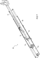
- reference numeral 1 indicates, as a whole, an aerial work platform comprising a tracked vehicle 2 provided with a stabilizer device 3 of a known type suitable to stabilize the aerial work platform 1 in use.
- the device 3 comprises a plurality of oscillating arms 4 (in this case four arms 4), each of which is rotatably coupled to the vehicle 2 so as to oscillate, with respect to the vehicle 2, around a respective substantially horizontal fulcrum axis 5 between a rest position ( Figure 1 ) and an operating position (not shown).
- the vehicle 2 further supports a rotating turret 6, which extends upwards from the vehicle 2 and is rotatably coupled to the vehicle 2 so as to rotate, with respect to the vehicle 2 and under the thrust of an operating device, of a known type and not shown, around a substantially vertical axis of rotation 7.
- the aerial work platform 1 further comprises a people-holding cage 8 of a known type, which has a substantially horizontal supporting surface P and is connected to the turret 6 by the interposition of a lifting unit 9 configured to move the cage 8 between a lowered rest position ( Figure 1 ) and a plurality of raised operating positions (not shown).
- the unit 9 comprises a plurality of lifting arms (in this case three lifting arms 10, 11, 12) arranged in succession and connected together in a known manner.
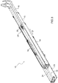
- the arm 10 is a telescopic arm comprising an axially fixed section bar 13 connected to the turret 6, and three movable section bars 14, 15, 16, of which the section bar 14 is fitted inside the section bar 13 and slidably coupled thereto, the section bar 15 is fitted inside the section bar 14 and slidably coupled thereto, and the section bar 16 is connected to the arm 11 and fitted inside the section bar 15 and slidably coupled thereto.
- the section bars 14, 15, 16 have a parallelepiped shape with a substantially rectangular section and are movable between a retracted position ( Figure 1 ), in which the arm 10 has its minimum length, and an extracted position (not shown), in which the arm 10 has its maximum length.
- the section bars 14, 15, 16 are moved between the aforesaid retracted and extracted positions in a substantially rectilinear direction of movement 17 by an operating device 18 comprising an actuator cylinder 19, to move the section bar 14 between its retracted and extracted positions, a pair of rope-operated systems 20, 21, to move the section bar 15 between its extracted and retracted positions, and a pair of rope-operated systems 22, 23, to move the section bar 16 between its extracted and retracted positions.
- an operating device 18 comprising an actuator cylinder 19, to move the section bar 14 between its retracted and extracted positions, a pair of rope-operated systems 20, 21, to move the section bar 15 between its extracted and retracted positions, and a pair of rope-operated systems 22, 23, to move the section bar 16 between its extracted and retracted positions.
- the cylinder 19 extends inside the arm 10, is fixed to the section bar 14 parallel to direction 17, and has an output rod 24 fastened to the section bar 13.
- the system 20 is fitted inside the arm 10, and in this case comprises a pair of pulleys 25 rotatably mounted at one free end of the cylinder 19, hence of the section bar 14, to move integrally with the section bar 14 in direction 17.
- the system 20 further comprises a pair of ropes 26, each of which is wound around a respective pulley 25 and has two free ends, one fixed to the section bar 13 and the other one to the section bar 15.
- the system 22 is fitted inside the arm 10, and in this case comprises a pair of pulleys 27 rotatably mounted at one free end of the section bar 15, to move integrally with the section bar 15 in direction 17.
- the system 22 further comprises a pair of ropes 28, each of which is wound around a respective pulley 27 and has two free ends, one fixed to the section bar 14 and the other one to the section bar 16.
- the actuation of the cylinder 19 to move the section bar 14 from its retracted position to its extracted position involves both the movement of the pulleys 25 in direction 17, therefore the dragging of the section bar 15 by the ropes 26, and the movement of the pulleys 27 in direction 17, therefore the dragging of the section bar 16 by the ropes 28.
- the actuation of the cylinder 19 to move the section bar 14 from its retracted position to its extracted position allows the two rope-operated systems 20, 22 to directly move the section bars 15 and 16 from their retracted positions to their extracted positions.
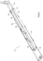
- the system 21 is fitted inside the arm 10, and in this case comprises a pair of pulleys 29, which are rotatably mounted at one free end of the section bar 14 opposite the free end of the section bar 14 on which the pulleys 25 are mounted, and are movable integrally with the section bar 14 in direction 17.
- the system 21 further comprises a pair of ropes 30, each of which is wound around a respective pulley 29 and has two free ends, one fixed to the section bar 13 and the other one to the section bar 15.
- the system 23 is fitted inside the arm 10, and in this case comprises a pair of pulleys 31, which are rotatably mounted at one free end of the section bar 15 opposite the free end of the section bar 15 on which the pulleys 27 are mounted, and are movable integrally with the section bar 15 in direction 17.
- the system 23 further comprises a pair of ropes 32, each of which is wound around a respective pulley 31 and has two free ends, one fixed to the section bar 14 and the other one to the section bar 16.
- the actuation of the cylinder 19 to move the section bar 14 from its extracted position to its retracted position involves both the movement of the pulleys 29 in direction 17, therefore the dragging of the section bar 15 by the ropes 30, and the movement of the pulleys 31 in direction 17, therefore the dragging of the section bar 16 by the ropes 32.
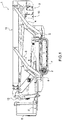
- the unit 9 further comprises a plurality of pipes 33 (in this case four pipes 33, only two of which are shown in Figures 8 and 9 ) fitted inside the arm 10 to feed an operating fluid, usually oil, along the arm 10 to at least one user (not shown) connected above the arm 10.
- a plurality of pipes 33 in this case four pipes 33, only two of which are shown in Figures 8 and 9 .
- Each pipe 33 comprises a flexible segment 34 housed inside a cable-holding chain 35, which is fitted inside the arm 10 and fixed at its free ends to the section bar 15 and the section bar 16, to guide the flexible segment 34 during the movements of the section bar 16 between its extracted and retracted positions.
- the flexible segment 34 is fastened to the section bars 15 and 16, configured to feed the operating fluid from the section bar 15 to the section bar 16, and connected to a further flexible or rigid segment (not shown) of the pipe 33 fixed along the section bar 16.
- Each pipe 33 further comprises a flexible segment 36 ( Figures 8 and 9 ), which has one first free end 37 fastened to the section bar 13, is wound around a respective pulley 38 rotatably mounted at one open free end of the section bar 14, extends inside the section bar 14, and has one second free end (not shown) fastened to the section bar 15.
- the flexible segment 36 is configured to feed the operating fluid from the section bar 13 to the section bar 15, is connected to the flexible segment 34, and also connected to a further flexible or rigid segment (not shown) of the pipe 33 fixed along the section bar 13.
- the flexible segment 36 is housed inside the arm 10, and extends parallel to direction 17 inside a hollow space defined between the section bar 13 and the section bar 14.
- the pulleys 38 define part of a guide device 39 further comprising, in this case, two sliding guides 40 formed on the section bar 14 and slidably engaged by the flexible segments 36 of the pipes 33 and, for each pulley 38, a respective countering roller 41 mounted on the section bar 14.
- the aerial work platform 1 Since the flexible segments 36 of the pipes 33 are guided within the hollow space defined between the section bar 13 and the section bar 14 and by the guide device 39, the aerial work platform 1 has some advantages mainly due to the fact that the flexible segments 36 of the pipes 33 do not have to be guided within a cable-holding chain similar to the cable-holding chain 35 and that, consequently, the assembly defined by the actuator cylinder 19, the rope-operated systems 20, 21, 22, 23, the pipes 33 and the cable-holding chain 35 can be entirely housed inside the arm 10.
Landscapes
- Engineering & Computer Science (AREA)
- Structural Engineering (AREA)
- Mechanical Engineering (AREA)
- Life Sciences & Earth Sciences (AREA)
- Geology (AREA)
- Forklifts And Lifting Vehicles (AREA)
- Axle Suspensions And Sidecars For Cycles (AREA)
Priority Applications (2)
| Application Number | Priority Date | Filing Date | Title |
|---|---|---|---|
| EP21166854.6A EP3896022B1 (de) | 2018-04-16 | 2019-04-16 | Luftarbeitsplattform |
| DK21166854.6T DK3896022T3 (da) | 2018-04-16 | 2019-04-16 | Luftarbejdsplatform |
Applications Claiming Priority (1)
| Application Number | Priority Date | Filing Date | Title |
|---|---|---|---|
| IT102018000004537A IT201800004537A1 (it) | 2018-04-16 | 2018-04-16 | Piattaforma aerea |
Related Child Applications (2)
| Application Number | Title | Priority Date | Filing Date |
|---|---|---|---|
| EP21166854.6A Division EP3896022B1 (de) | 2018-04-16 | 2019-04-16 | Luftarbeitsplattform |
| EP21166854.6A Division-Into EP3896022B1 (de) | 2018-04-16 | 2019-04-16 | Luftarbeitsplattform |
Publications (2)
| Publication Number | Publication Date |
|---|---|
| EP3556715A1 true EP3556715A1 (de) | 2019-10-23 |
| EP3556715B1 EP3556715B1 (de) | 2021-06-02 |
Family
ID=62952217
Family Applications (2)
| Application Number | Title | Priority Date | Filing Date |
|---|---|---|---|
| EP19169650.9A Active EP3556715B1 (de) | 2018-04-16 | 2019-04-16 | Arbeitsbühne |
| EP21166854.6A Active EP3896022B1 (de) | 2018-04-16 | 2019-04-16 | Luftarbeitsplattform |
Family Applications After (1)
| Application Number | Title | Priority Date | Filing Date |
|---|---|---|---|
| EP21166854.6A Active EP3896022B1 (de) | 2018-04-16 | 2019-04-16 | Luftarbeitsplattform |
Country Status (4)
| Country | Link |
|---|---|
| US (3) | US20190315612A1 (de) |
| EP (2) | EP3556715B1 (de) |
| DK (2) | DK3896022T3 (de) |
| IT (1) | IT201800004537A1 (de) |
Families Citing this family (2)
| Publication number | Priority date | Publication date | Assignee | Title |
|---|---|---|---|---|
| CN111153333B (zh) * | 2020-01-22 | 2024-07-05 | 徐工消防安全装备有限公司 | 一种伸缩式工作臂、伸缩作业装置及举高消防车 |
| CN115123978A (zh) * | 2022-05-24 | 2022-09-30 | 安徽明诚电力设备安装有限公司 | 一种电力设备辅助安装维修装置 |
Citations (3)
| Publication number | Priority date | Publication date | Assignee | Title |
|---|---|---|---|---|
| FR2681649A1 (fr) * | 1991-09-24 | 1993-03-26 | Krupp Industrietech | Systeme de telescopage hydromecanique, notamment pour grue automobile. |
| EP2520530A1 (de) * | 2011-05-06 | 2012-11-07 | B.O.B. Sistemi Idraulici S.p.A. | Teleskoparm für einen Kran mit beweglichen Befestigungselement |
| WO2014095803A1 (en) * | 2012-12-20 | 2014-06-26 | Cnh America Llc | A telescopic boom |
Family Cites Families (43)
| Publication number | Priority date | Publication date | Assignee | Title |
|---|---|---|---|---|
| US2999600A (en) * | 1959-09-04 | 1961-09-12 | Gates Earl | Compensating telescopic boom |
| US3462023A (en) * | 1967-07-12 | 1969-08-19 | Grove Mfg Co | Reinforcement member for telescoping boom assembly |
| US3638806A (en) * | 1969-08-01 | 1972-02-01 | Bliss & Laughlin Ind | Portable crane with extendable boom |
| DE2018926C2 (de) * | 1970-01-31 | 1982-07-08 | Tadano Ironworks Co.Ltd., Takamatsu | Teleskopausleger für einen Kran |
| US3817007A (en) * | 1971-10-04 | 1974-06-18 | Altec Mfg Co Inc | Aerial lift mechanism |
| US3809249A (en) * | 1972-03-15 | 1974-05-07 | Fulton Industries | Telescopic crane boom with chain actuation of fly section |
| US3807108A (en) * | 1972-09-18 | 1974-04-30 | Harnischfeger Corp | Structural design of boom section with inverted {37 a{38 {11 frame cross-section |
| US3777629A (en) * | 1972-09-18 | 1973-12-11 | Harnischfeger Corp | Hydraulic cylinder for telescopic boom |
| US3804262A (en) * | 1972-09-18 | 1974-04-16 | Harnischfeger Corp | Telescopic boom |
| US3842985A (en) * | 1972-12-15 | 1974-10-22 | Harnischfeger Corp | Means for extending and retracting crane boom section |
| US3966018A (en) * | 1975-02-12 | 1976-06-29 | Morita Pump Kabushiki Kaisha | Working platform lifting apparatus for aerial ladder truck |
| US4011699A (en) * | 1975-08-27 | 1977-03-15 | Fmc Corporation | Telescopic boom quick retract hydraulic circuit |
| SE410410B (sv) * | 1976-06-23 | 1979-10-15 | Inst Elektroswarki Patona | Anlaeggning foer framstaellning av metallgoet med stor vikt genom elektroslaggraffinering |
| GB1594096A (en) * | 1976-11-11 | 1981-07-30 | Coles Cranes Ltd | Telescopic booms |
| USRE30905E (en) * | 1976-11-11 | 1982-04-20 | Coles Crane Ltd. | Multi-section telescopic boom |
| US4133411A (en) * | 1977-02-11 | 1979-01-09 | Chamberlain Manufacturing Corporation | Extensible boom |
| SE402753B (sv) * | 1977-03-21 | 1978-07-17 | Jonsereds Fabrikers Ab | Anordning av slangforing och hydroulkoppling vid hydrauliskt manovrerad kran |
| US4185426A (en) * | 1978-01-30 | 1980-01-29 | A-T-O Inc. | Extension/elevation intra-action device for aerial lift apparatus |
| US4352434A (en) * | 1980-05-01 | 1982-10-05 | Fmc Corporation | Pendant supported hydraulic extensible boom |
| US4406375A (en) * | 1980-07-02 | 1983-09-27 | Jlg Industries Inc. | Telescopic boom construction |
| US4489838A (en) * | 1981-08-17 | 1984-12-25 | Fmc Corporation | Low droop multi-part pendant supported boom |
| US4514939A (en) * | 1981-08-17 | 1985-05-07 | Fmc Corporation | Extensible boom with manual section stored in base |
| US4592474A (en) * | 1981-08-17 | 1986-06-03 | Fmc Corporation | Coupling and latching mechanism for extensible boom |
| US4492311A (en) * | 1981-08-17 | 1985-01-08 | Fmc Corporation | Coupling and latching mechanism for extensible boom |
| US4506480A (en) * | 1983-03-10 | 1985-03-26 | Calavar Corporation | Extensible boom construction for self-propelled aerial work platforms |
| US4575976A (en) * | 1983-06-24 | 1986-03-18 | Machine Products Corporation | Extension and retraction system for boom apparatus |
| US4585132A (en) * | 1984-09-10 | 1986-04-29 | Fmc Corporation | Extensible boom with manual section stored in base |
| US5060427A (en) * | 1990-02-01 | 1991-10-29 | Kidde Industries, Inc. | Extension and retraction system for four section telescopic boom having simultaneous and equal extension and retraction of the telescopic sections |
| GB2263270B (en) * | 1992-01-20 | 1995-01-11 | D J Ind Ltd | Load handling apparatus |
| GB2264282B (en) * | 1992-02-20 | 1995-04-12 | Lansing Linde Ltd | Lift trucks and extensible mast structures therefor |
| US5375348A (en) * | 1992-04-23 | 1994-12-27 | Japanic Corporation | Deep excavator |
| DE4311964A1 (de) * | 1993-04-10 | 1994-10-13 | Krupp Ag Hoesch Krupp | Teleskopauslegerkran |
| DE19613700A1 (de) * | 1996-03-29 | 1997-10-02 | M E P Gmbh Ges Fuer Consulting | Teleskopartig auseinanderfahrbarer Maschinenteil |
| US5695082A (en) * | 1996-04-08 | 1997-12-09 | Pioneer Engineering | Crane having a readily removable outer boom section |
| ES2287505T3 (es) * | 2002-05-03 | 2007-12-16 | Clark Equipment Company | Portador de manguera hidraulica retirable. |
| ITTO20030957A1 (it) * | 2003-11-28 | 2005-05-29 | Cnh Italia Spa | Braccio sollevatore telescopico. |
| US20060086566A1 (en) * | 2004-07-29 | 2006-04-27 | Oshkosh Truck Corporation | Boom assembly |
| ITMI20040405U1 (it) * | 2004-09-02 | 2004-12-02 | Kabelschlepp Italia S R L | Disposizione migliorata di catena portachiavi in posizione verticale ascendente inserita in gruppi telescopici a due o piu' sezioni |
| ITMO20120170A1 (it) * | 2012-07-06 | 2014-01-07 | C M C S R L Societa Unipersonal E | Braccio telescopico per macchine operatrici |
| US9791071B2 (en) * | 2013-03-07 | 2017-10-17 | Oshkosh Corporation | Internally supported power track |
| JP6665874B2 (ja) * | 2018-02-16 | 2020-03-13 | 株式会社タダノ | クレーン |
| JP6627898B2 (ja) * | 2018-02-16 | 2020-01-08 | 株式会社タダノ | クレーン |
| US11401135B2 (en) * | 2018-03-12 | 2022-08-02 | Manitowoc Crane Companies, Llc | Pinned telescoping crane boom |
-
2018
- 2018-04-16 IT IT102018000004537A patent/IT201800004537A1/it unknown
-
2019
- 2019-04-15 US US16/384,594 patent/US20190315612A1/en not_active Abandoned
- 2019-04-16 EP EP19169650.9A patent/EP3556715B1/de active Active
- 2019-04-16 EP EP21166854.6A patent/EP3896022B1/de active Active
- 2019-04-16 DK DK21166854.6T patent/DK3896022T3/da active
- 2019-04-16 DK DK19169650.9T patent/DK3556715T3/da active
-
2024
- 2024-01-26 US US18/424,462 patent/US20240359962A1/en active Pending
- 2024-08-26 US US18/815,097 patent/US20240417231A1/en active Pending
Patent Citations (3)
| Publication number | Priority date | Publication date | Assignee | Title |
|---|---|---|---|---|
| FR2681649A1 (fr) * | 1991-09-24 | 1993-03-26 | Krupp Industrietech | Systeme de telescopage hydromecanique, notamment pour grue automobile. |
| EP2520530A1 (de) * | 2011-05-06 | 2012-11-07 | B.O.B. Sistemi Idraulici S.p.A. | Teleskoparm für einen Kran mit beweglichen Befestigungselement |
| WO2014095803A1 (en) * | 2012-12-20 | 2014-06-26 | Cnh America Llc | A telescopic boom |
Also Published As
| Publication number | Publication date |
|---|---|
| DK3896022T3 (da) | 2024-06-10 |
| US20240417231A1 (en) | 2024-12-19 |
| EP3896022B1 (de) | 2024-05-29 |
| EP3896022A1 (de) | 2021-10-20 |
| IT201800004537A1 (it) | 2019-10-16 |
| US20190315612A1 (en) | 2019-10-17 |
| US20240359962A1 (en) | 2024-10-31 |
| EP3556715B1 (de) | 2021-06-02 |
| DK3556715T3 (da) | 2021-08-16 |
Similar Documents
| Publication | Publication Date | Title |
|---|---|---|
| US20240359962A1 (en) | Aerial work platform | |
| EP2935082B1 (de) | Teleskopischer ausleger | |
| US8671626B1 (en) | Apparatus and method for a drilling rig assembly | |
| US2911111A (en) | Mobile hydraulic crane | |
| EP3237688B1 (de) | Stapelumkehrsystem | |
| CN106414149B (zh) | 用于起重机、集装箱起重机、ertg和运送装置的具有伸缩臂的集电系统 | |
| EP3199485A2 (de) | Teleskopausleger für selbstangetriebene arbeitsmaschinen | |
| CN105293317A (zh) | 稳定设备 | |
| US9815669B2 (en) | Telescopic arm for operating machines | |
| EP3174821B1 (de) | Teleskopausleger für arbeitsmaschinen | |
| JP6839965B2 (ja) | マニピュレータ装置 | |
| RU2016107760A (ru) | Скип и направляющая рама | |
| CN105293319A (zh) | 支腿伸缩联动机构 | |
| CN105084231B (zh) | 伸缩臂装置和工程机械 | |
| CN110040631A (zh) | 起重机操纵室升降装置及起重机 | |
| EP3260398A1 (de) | Vorrichtung zur handhabung von artikeln | |
| WO2017153724A1 (en) | Elevating platform | |
| EP2462046B1 (de) | Vorrichtung zur teilehandhabung | |
| EP3872022A1 (de) | Teleskopausleger sowie mit dem teleskopausleger ausgestatteter kran und fahrzeug | |
| CN105858508A (zh) | 一种支腿伸缩机构及具有其的汽车起重机 | |
| US20240336466A1 (en) | Telescopic arm for self-propelled operating machines | |
| JP6151064B2 (ja) | 車載用荷役台昇降装置 | |
| CN114195056A (zh) | 一种同步伸缩四节伸缩臂内置式拖链 | |
| SU1720853A1 (ru) | Манипул тор | |
| KR101412107B1 (ko) | 좌굴 방지 장치 |
Legal Events
| Date | Code | Title | Description |
|---|---|---|---|
| PUAI | Public reference made under article 153(3) epc to a published international application that has entered the european phase |
Free format text: ORIGINAL CODE: 0009012 |
|
| STAA | Information on the status of an ep patent application or granted ep patent |
Free format text: STATUS: THE APPLICATION HAS BEEN PUBLISHED |
|
| AK | Designated contracting states |
Kind code of ref document: A1 Designated state(s): AL AT BE BG CH CY CZ DE DK EE ES FI FR GB GR HR HU IE IS IT LI LT LU LV MC MK MT NL NO PL PT RO RS SE SI SK SM TR |
|
| AX | Request for extension of the european patent |
Extension state: BA ME |
|
| STAA | Information on the status of an ep patent application or granted ep patent |
Free format text: STATUS: REQUEST FOR EXAMINATION WAS MADE |
|
| 17P | Request for examination filed |
Effective date: 20200331 |
|
| RBV | Designated contracting states (corrected) |
Designated state(s): AL AT BE BG CH CY CZ DE DK EE ES FI FR GB GR HR HU IE IS IT LI LT LU LV MC MK MT NL NO PL PT RO RS SE SI SK SM TR |
|
| GRAP | Despatch of communication of intention to grant a patent |
Free format text: ORIGINAL CODE: EPIDOSNIGR1 |
|
| STAA | Information on the status of an ep patent application or granted ep patent |
Free format text: STATUS: GRANT OF PATENT IS INTENDED |
|
| INTG | Intention to grant announced |
Effective date: 20201113 |
|
| RIN1 | Information on inventor provided before grant (corrected) |
Inventor name: POLTRONIERI, ZENO |
|
| GRAS | Grant fee paid |
Free format text: ORIGINAL CODE: EPIDOSNIGR3 |
|
| GRAA | (expected) grant |
Free format text: ORIGINAL CODE: 0009210 |
|
| STAA | Information on the status of an ep patent application or granted ep patent |
Free format text: STATUS: THE PATENT HAS BEEN GRANTED |
|
| REG | Reference to a national code |
Ref country code: CH Ref legal event code: EP |
|
| AK | Designated contracting states |
Kind code of ref document: B1 Designated state(s): AL AT BE BG CH CY CZ DE DK EE ES FI FR GB GR HR HU IE IS IT LI LT LU LV MC MK MT NL NO PL PT RO RS SE SI SK SM TR |
|
| REG | Reference to a national code |
Ref country code: GB Ref legal event code: FG4D |
|
| REG | Reference to a national code |
Ref country code: AT Ref legal event code: REF Ref document number: 1398288 Country of ref document: AT Kind code of ref document: T Effective date: 20210615 |
|
| REG | Reference to a national code |
Ref country code: IE Ref legal event code: FG4D |
|
| REG | Reference to a national code |
Ref country code: DE Ref legal event code: R096 Ref document number: 602019004988 Country of ref document: DE |
|
| REG | Reference to a national code |
Ref country code: DK Ref legal event code: T3 Effective date: 20210810 |
|
| REG | Reference to a national code |
Ref country code: LT Ref legal event code: MG9D |
|
| PG25 | Lapsed in a contracting state [announced via postgrant information from national office to epo] |
Ref country code: BG Free format text: LAPSE BECAUSE OF FAILURE TO SUBMIT A TRANSLATION OF THE DESCRIPTION OR TO PAY THE FEE WITHIN THE PRESCRIBED TIME-LIMIT Effective date: 20210902 Ref country code: FI Free format text: LAPSE BECAUSE OF FAILURE TO SUBMIT A TRANSLATION OF THE DESCRIPTION OR TO PAY THE FEE WITHIN THE PRESCRIBED TIME-LIMIT Effective date: 20210602 Ref country code: LT Free format text: LAPSE BECAUSE OF FAILURE TO SUBMIT A TRANSLATION OF THE DESCRIPTION OR TO PAY THE FEE WITHIN THE PRESCRIBED TIME-LIMIT Effective date: 20210602 Ref country code: HR Free format text: LAPSE BECAUSE OF FAILURE TO SUBMIT A TRANSLATION OF THE DESCRIPTION OR TO PAY THE FEE WITHIN THE PRESCRIBED TIME-LIMIT Effective date: 20210602 |
|
| REG | Reference to a national code |
Ref country code: NL Ref legal event code: MP Effective date: 20210602 |
|
| REG | Reference to a national code |
Ref country code: AT Ref legal event code: MK05 Ref document number: 1398288 Country of ref document: AT Kind code of ref document: T Effective date: 20210602 |
|
| PG25 | Lapsed in a contracting state [announced via postgrant information from national office to epo] |
Ref country code: PL Free format text: LAPSE BECAUSE OF FAILURE TO SUBMIT A TRANSLATION OF THE DESCRIPTION OR TO PAY THE FEE WITHIN THE PRESCRIBED TIME-LIMIT Effective date: 20210602 Ref country code: NO Free format text: LAPSE BECAUSE OF FAILURE TO SUBMIT A TRANSLATION OF THE DESCRIPTION OR TO PAY THE FEE WITHIN THE PRESCRIBED TIME-LIMIT Effective date: 20210902 Ref country code: LV Free format text: LAPSE BECAUSE OF FAILURE TO SUBMIT A TRANSLATION OF THE DESCRIPTION OR TO PAY THE FEE WITHIN THE PRESCRIBED TIME-LIMIT Effective date: 20210602 Ref country code: RS Free format text: LAPSE BECAUSE OF FAILURE TO SUBMIT A TRANSLATION OF THE DESCRIPTION OR TO PAY THE FEE WITHIN THE PRESCRIBED TIME-LIMIT Effective date: 20210602 Ref country code: SE Free format text: LAPSE BECAUSE OF FAILURE TO SUBMIT A TRANSLATION OF THE DESCRIPTION OR TO PAY THE FEE WITHIN THE PRESCRIBED TIME-LIMIT Effective date: 20210602 Ref country code: GR Free format text: LAPSE BECAUSE OF FAILURE TO SUBMIT A TRANSLATION OF THE DESCRIPTION OR TO PAY THE FEE WITHIN THE PRESCRIBED TIME-LIMIT Effective date: 20210903 |
|
| PG25 | Lapsed in a contracting state [announced via postgrant information from national office to epo] |
Ref country code: ES Free format text: LAPSE BECAUSE OF FAILURE TO SUBMIT A TRANSLATION OF THE DESCRIPTION OR TO PAY THE FEE WITHIN THE PRESCRIBED TIME-LIMIT Effective date: 20210602 Ref country code: EE Free format text: LAPSE BECAUSE OF FAILURE TO SUBMIT A TRANSLATION OF THE DESCRIPTION OR TO PAY THE FEE WITHIN THE PRESCRIBED TIME-LIMIT Effective date: 20210602 Ref country code: SK Free format text: LAPSE BECAUSE OF FAILURE TO SUBMIT A TRANSLATION OF THE DESCRIPTION OR TO PAY THE FEE WITHIN THE PRESCRIBED TIME-LIMIT Effective date: 20210602 Ref country code: AT Free format text: LAPSE BECAUSE OF FAILURE TO SUBMIT A TRANSLATION OF THE DESCRIPTION OR TO PAY THE FEE WITHIN THE PRESCRIBED TIME-LIMIT Effective date: 20210602 Ref country code: CZ Free format text: LAPSE BECAUSE OF FAILURE TO SUBMIT A TRANSLATION OF THE DESCRIPTION OR TO PAY THE FEE WITHIN THE PRESCRIBED TIME-LIMIT Effective date: 20210602 Ref country code: NL Free format text: LAPSE BECAUSE OF FAILURE TO SUBMIT A TRANSLATION OF THE DESCRIPTION OR TO PAY THE FEE WITHIN THE PRESCRIBED TIME-LIMIT Effective date: 20210602 Ref country code: PT Free format text: LAPSE BECAUSE OF FAILURE TO SUBMIT A TRANSLATION OF THE DESCRIPTION OR TO PAY THE FEE WITHIN THE PRESCRIBED TIME-LIMIT Effective date: 20211004 Ref country code: RO Free format text: LAPSE BECAUSE OF FAILURE TO SUBMIT A TRANSLATION OF THE DESCRIPTION OR TO PAY THE FEE WITHIN THE PRESCRIBED TIME-LIMIT Effective date: 20210602 Ref country code: SM Free format text: LAPSE BECAUSE OF FAILURE TO SUBMIT A TRANSLATION OF THE DESCRIPTION OR TO PAY THE FEE WITHIN THE PRESCRIBED TIME-LIMIT Effective date: 20210602 |
|
| REG | Reference to a national code |
Ref country code: DE Ref legal event code: R097 Ref document number: 602019004988 Country of ref document: DE |
|
| PLBE | No opposition filed within time limit |
Free format text: ORIGINAL CODE: 0009261 |
|
| STAA | Information on the status of an ep patent application or granted ep patent |
Free format text: STATUS: NO OPPOSITION FILED WITHIN TIME LIMIT |
|
| 26N | No opposition filed |
Effective date: 20220303 |
|
| PG25 | Lapsed in a contracting state [announced via postgrant information from national office to epo] |
Ref country code: AL Free format text: LAPSE BECAUSE OF FAILURE TO SUBMIT A TRANSLATION OF THE DESCRIPTION OR TO PAY THE FEE WITHIN THE PRESCRIBED TIME-LIMIT Effective date: 20210602 |
|
| PG25 | Lapsed in a contracting state [announced via postgrant information from national office to epo] |
Ref country code: IT Free format text: LAPSE BECAUSE OF FAILURE TO SUBMIT A TRANSLATION OF THE DESCRIPTION OR TO PAY THE FEE WITHIN THE PRESCRIBED TIME-LIMIT Effective date: 20210602 |
|
| REG | Reference to a national code |
Ref country code: CH Ref legal event code: PL |
|
| REG | Reference to a national code |
Ref country code: BE Ref legal event code: MM Effective date: 20220430 |
|
| PG25 | Lapsed in a contracting state [announced via postgrant information from national office to epo] |
Ref country code: MC Free format text: LAPSE BECAUSE OF FAILURE TO SUBMIT A TRANSLATION OF THE DESCRIPTION OR TO PAY THE FEE WITHIN THE PRESCRIBED TIME-LIMIT Effective date: 20210602 Ref country code: LU Free format text: LAPSE BECAUSE OF NON-PAYMENT OF DUE FEES Effective date: 20220416 Ref country code: LI Free format text: LAPSE BECAUSE OF NON-PAYMENT OF DUE FEES Effective date: 20220430 Ref country code: CH Free format text: LAPSE BECAUSE OF NON-PAYMENT OF DUE FEES Effective date: 20220430 |
|
| PG25 | Lapsed in a contracting state [announced via postgrant information from national office to epo] |
Ref country code: BE Free format text: LAPSE BECAUSE OF NON-PAYMENT OF DUE FEES Effective date: 20220430 |
|
| PG25 | Lapsed in a contracting state [announced via postgrant information from national office to epo] |
Ref country code: IE Free format text: LAPSE BECAUSE OF NON-PAYMENT OF DUE FEES Effective date: 20220416 |
|
| PG25 | Lapsed in a contracting state [announced via postgrant information from national office to epo] |
Ref country code: HU Free format text: LAPSE BECAUSE OF FAILURE TO SUBMIT A TRANSLATION OF THE DESCRIPTION OR TO PAY THE FEE WITHIN THE PRESCRIBED TIME-LIMIT; INVALID AB INITIO Effective date: 20190416 |
|
| PG25 | Lapsed in a contracting state [announced via postgrant information from national office to epo] |
Ref country code: MK Free format text: LAPSE BECAUSE OF FAILURE TO SUBMIT A TRANSLATION OF THE DESCRIPTION OR TO PAY THE FEE WITHIN THE PRESCRIBED TIME-LIMIT Effective date: 20210602 Ref country code: CY Free format text: LAPSE BECAUSE OF FAILURE TO SUBMIT A TRANSLATION OF THE DESCRIPTION OR TO PAY THE FEE WITHIN THE PRESCRIBED TIME-LIMIT Effective date: 20210602 |
|
| PG25 | Lapsed in a contracting state [announced via postgrant information from national office to epo] |
Ref country code: TR Free format text: LAPSE BECAUSE OF FAILURE TO SUBMIT A TRANSLATION OF THE DESCRIPTION OR TO PAY THE FEE WITHIN THE PRESCRIBED TIME-LIMIT Effective date: 20210602 |
|
| PG25 | Lapsed in a contracting state [announced via postgrant information from national office to epo] |
Ref country code: MT Free format text: LAPSE BECAUSE OF FAILURE TO SUBMIT A TRANSLATION OF THE DESCRIPTION OR TO PAY THE FEE WITHIN THE PRESCRIBED TIME-LIMIT Effective date: 20210602 |
|
| PGFP | Annual fee paid to national office [announced via postgrant information from national office to epo] |
Ref country code: DE Payment date: 20250428 Year of fee payment: 7 |
|
| PGFP | Annual fee paid to national office [announced via postgrant information from national office to epo] |
Ref country code: GB Payment date: 20250422 Year of fee payment: 7 Ref country code: DK Payment date: 20250424 Year of fee payment: 7 |
|
| PGFP | Annual fee paid to national office [announced via postgrant information from national office to epo] |
Ref country code: FR Payment date: 20250424 Year of fee payment: 7 |