EP3556633B1 - Capot avant pour un véhicule ferroviaire, procédé de montage d'au moins un capot avant et wagon de véhicule ferroviaire doté d'au moins un capot avant - Google Patents
Capot avant pour un véhicule ferroviaire, procédé de montage d'au moins un capot avant et wagon de véhicule ferroviaire doté d'au moins un capot avant Download PDFInfo
- Publication number
- EP3556633B1 EP3556633B1 EP19169255.7A EP19169255A EP3556633B1 EP 3556633 B1 EP3556633 B1 EP 3556633B1 EP 19169255 A EP19169255 A EP 19169255A EP 3556633 B1 EP3556633 B1 EP 3556633B1
- Authority
- EP
- European Patent Office
- Prior art keywords
- cover member
- front cap
- hood
- cover
- rail vehicle
- Prior art date
- Legal status (The legal status is an assumption and is not a legal conclusion. Google has not performed a legal analysis and makes no representation as to the accuracy of the status listed.)
- Active
Links
Images
Classifications
-
- B—PERFORMING OPERATIONS; TRANSPORTING
- B61—RAILWAYS
- B61D—BODY DETAILS OR KINDS OF RAILWAY VEHICLES
- B61D17/00—Construction details of vehicle bodies
- B61D17/04—Construction details of vehicle bodies with bodies of metal; with composite, e.g. metal and wood body structures
- B61D17/043—Construction details of vehicle bodies with bodies of metal; with composite, e.g. metal and wood body structures connections between superstructure sub-units
- B61D17/046—Construction details of vehicle bodies with bodies of metal; with composite, e.g. metal and wood body structures connections between superstructure sub-units readily releasable, i.e. dismountable or collapsible sub-units, e.g. for shipping
-
- B—PERFORMING OPERATIONS; TRANSPORTING
- B61—RAILWAYS
- B61D—BODY DETAILS OR KINDS OF RAILWAY VEHICLES
- B61D17/00—Construction details of vehicle bodies
- B61D17/04—Construction details of vehicle bodies with bodies of metal; with composite, e.g. metal and wood body structures
- B61D17/06—End walls
Definitions
- the invention relates to a front hood for a rail vehicle car, a method for assembling at least one front hood and a rail vehicle car with at least one front hood.
- an end car of a rail vehicle can have a front hood, for example made of a glass fiber reinforced plastic (GRP).
- the front hood is used to cover the driver's area and is often aerodynamically shaped.
- the front hood can be self-supporting and attached directly to a car body of the end car.
- the front hood can be attached to a scaffolding structure that contains the driver's compartment area.
- the disadvantage of both alternatives is that if the front hood is damaged, the entire front hood must be replaced.
- the pamphlet CN203592984U describes a high-speed train with a front hood that is divided and has a train head cover and a head structure.
- the head structure is a separate module.
- the disadvantage here is that the traction head cover and the head structure are each components with very large dimensions, the replacement of which is costly.
- the pamphlet CN103802848U discloses a high speed train having a hood structure that is horizontally divided and has an upper hood and a lower hood. It is also disadvantageous here that the upper hood and the lower hood are each components with very large dimensions, the replacement of which is cost-intensive.
- the document DE102016205305A1 describes a locomotive comprising a car body with a head end having a front nose. In the area of its head end, the car body has an interface which is designed and provided for attaching and connecting differently shaped front lugs that form a set of variants. These front lugs can therefore be easily exchanged together with side cover elements.
- the invention is therefore based on the object of creating a front hood and a method for assembling a front hood, wherein the front hood can be easily and inexpensively restored in the event of damage.
- This object is achieved according to the invention with a front hood for a rail vehicle car according to claim 1. Furthermore, the object is achieved with a method for assembling at least one front hood according to claim 12 and a rail vehicle carriage with at least one front hood according to claim 15. Advantageous refinements of the invention are contained in the subclaims.
- the front hood has at least four elements, namely the main element, the front element and the first cover element and the second cover element. In the event of damage, each of the four elements can be replaced independently of every other element. Damage occurs particularly often in the lower area of the front hood. Hence the first Cover element and the second cover element arranged interchangeably in a lower region of the front hood. In addition, damage often occurs in the front area in which the replaceable front element is located.
- the first lower edge and / or the second lower edge can have a partially or completely straight (eg horizontal), stepped, inclined and / or curved course.
- the front element, the first cover element and the second cover element each have smaller external dimensions than the main element. Due to the smaller dimensions, the front element, the first cover element and the second cover element can be manufactured inexpensively.
- first cover element and the second cover element can each have at least one opening for at least one energy dissipation element and / or the front element can have at least one maintenance flap.
- the first cover element and the second cover element each cover, among other things, an energy-absorbing element, which can also be referred to as an energy-absorbing element. Because of the opening, each energy-absorbing element can protrude from the first cover element and the second cover element and absorb impact energy before an element of the front hood is damaged.
- a maintenance flap enables easy access to an interior of the front hood, e.g. when filling windshield washer fluid.
- the front element, the first cover element and the second cover element or only the first cover element and the second cover element can form an opening for a coupling.
- the opening allows access to the coupling without the need for front flaps.
- the opening thus favors a simple design of the front hood.
- a closing device delimits the front hood downwards. This protects the interior of the front hood from dirt and damage, e.g. by flying gravel, protected. In addition, the closing device can improve aerodynamic behavior in a lower area of the front hood.
- the terminating device is preferably arranged behind the opening for the coupling. At the opening for the clutch, there is an air flow while driving, which generates vibrations and thus noise.
- the closing device can dampen this oscillation and reduce the development of noise.
- the terminating device is releasably attached to the front element or to the first cover element and the second cover element. If the opening for the coupling is limited at the top by the front element, the closing device can be attached directly to the front element. If the opening for the coupling is delimited at the top by the first cover element and the second cover element, the terminating device can be attached directly to the first cover element and the second cover element. This enables a simple fastening arrangement.
- the terminating device can have at least one terminating element which is inclined at an angle ⁇ to a longitudinal axis of the front hood.
- the inclined closing element can contribute to a reduction in vibrations and thus reduce the development of noise.
- a material of the closing device can have more favorable acoustic properties than a material of the front hood.
- the acoustic properties of the terminating device contribute advantageously to a reduction in noise.
- At least one insulating material can be applied to at least one inner surface of the terminating device.
- the insulating material also helps to reduce noise.
- the insulating material can also have thermally insulating properties.
- the closing element can have a steel material and a first thickness of 2 mm including a predetermined tolerance range and / or the insulating material can have mineral wool and a second thickness of 60 mm including a predetermined tolerance range.
- the first thickness and the second thickness are matched to one another, taking into account material properties.
- One advantage of the method according to the invention is that the assembly can take place in a few steps and is therefore cost-saving. A dismantling or replacement of an individual element is also easily possible, e.g. by removing and replacing only the front element, only the first cover element or only the second cover element. Of course, more than one element can be removed and replaced.
- a terminating device can be installed on the front element before step a) or a terminating device can be installed on the front element or on the first cover element and the second cover element after step c).
- the assembly sequence for the closing device is thus variable and can be adapted to the elements that form the opening for the coupling.
- maintenance flaps can be installed on the front element before or after step b).
- the assembly sequence for the maintenance hatches is thus also variable. If only one maintenance flap is damaged, it can also be replaced individually.
- the object is also achieved by a rail vehicle car with at least one front hood.
- the front hood can be attached to a car body and / or to a support structure of the rail vehicle car.
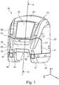
- the Fig. 1 shows a front hood 10 according to the invention of a rail vehicle carriage (not shown).
- the front hood 10 has a main element 20, a front element 30, a first cover element 41 and a second cover element 42.
- the main element 20 is made in one piece and has several areas, namely a roof area 21, a front area 22 with a front pane 25, a first side area 23 and a second side area 24.
- the areas can merge continuously or border one another with edges.
- Each area can have curved or flat surfaces.
- the main element 20 can, for example, be made of a glass fiber reinforced plastic (GRP).
- GFP glass fiber reinforced plastic
- the main element 20 can, for example, be fastened to a car body (not shown) or to a supporting structure of the rail vehicle (also not shown) and sealed with respect to this, e.g. with the aid of holder plates and screw connections (not shown) and also sealing elements (not shown).
- the front element 30 adjoins a front edge 50 of the front area 22 and is releasably attached to it.
- the front edge 50 runs predominantly in a straight line along a transverse axis y, but can also run predominantly curved or predominantly V-shaped.
- the front element 30 also adjoins the first side area 23 at a first side edge 51.
- the first side edge 51 runs in FIG Fig. 1 predominantly in a straight line along a vertical axis z, but can also run predominantly curved, stepped and / or inclined.
- the front element 30 also adjoins the second side area 24 at a second side edge 52.
- the second side edge 52 runs symmetrically to the first side edge 51 and is in Fig. 1 only partially shown.
- the front element 30 forms a first lower edge 53 with the first side area 23.
- the front element 30 forms a second lower edge 54 with the second side area 24.
- the front element 30 has a first maintenance flap 31 and a second maintenance flap 32, which can be opened and enable, for example, a filling of windshield washer fluid.
- the first maintenance flap 31 and the second maintenance flap 32 can be removable or, for example, with in Fig. 1 Hinges (not shown) can be attached to the front element 30.
- the first cover element 41 adjoins the first lower edge 53 and is releasably attached to it.
- the first cover element 41 has an opening 60 for a first energy dissipation element (not shown). Alternatively, the opening 60 can be omitted and the first energy-absorbing element can be completely covered.
- the second cover element 42 adjoins the second lower edge 54 and is releasably attached to it.
- the second cover element 42 has an opening 61 for a second energy dissipation element (not shown).
- the opening 61 can be omitted and the second energy-absorbing element can be completely covered.
- the front element 30, the main element 20, the first cover element 41 and the second cover element 42 are connected to one another with the aid of holder plates and screw connections (not shown) and sealed against one another with sealing elements (also not shown).
- the front element 30, the first cover element 41 and the second cover element 42 form an opening 62 for an in Fig. 2 Coupling 80 shown.
- an opening for the coupling 80 can only be formed by the first cover element 41 and the second cover element 42 if these adjoin one another above the coupling 80 and below the front element 30.
- a closing device 70 is arranged behind the opening 62 for the coupling 80, of which FIG Fig. 1 only one closing element 71 is shown.
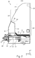
- FIG. 10 is a section through the front hood 10 along the line AA in FIG Fig. 1 shown.
- main element 20 Of the main element 20, only the roof area 21, the front area 22 and the second side area 24 as well as the second side edge 52 are shown here. Furthermore, the front element 30 and the second cover element 42 are shown.
- the terminating device 70 is arranged above the coupling 80 and the second cover element 42.
- the terminating device 70 has a flat terminating element 71 which is inclined at an angle ⁇ to the longitudinal axis x and otherwise runs in the transverse direction y.
- the terminating device 70 has a base element 72 which runs along a plane formed from the longitudinal axis x and the transverse axis y.
- the closing element 71 and the base element 72 can be made in one piece and have the same width in the transverse direction y.
- An insulating material 74 which is a thermal and / or acoustic insulating material 74, is arranged on an inner surface 73 of the terminating device 70. The insulating material 74 rests against the inner surface 73 and is in the Fig. 2 Shown with a small distance from the inner surface 73 only for reasons of better illustration.
- the closing device 70 and the first maintenance flap 31 as well as the second maintenance flap 32 are first attached to the front element 30.
- the main element 20 is then releasably fastened to the car body or to the support structure of the rail vehicle car.
- the front element 30 is then detachably attached to the main element 20.
- the first cover element 41 is detachably attached to the first lower edge 53
- the second cover element 42 is detachably attached to the second lower edge 54.
- the front element 30, the first cover element 41 and / or the second cover element 42 are damaged, only the damaged element can be replaced.
- the main element 20 can be retained.
- the closing element 71 contributes to a reduction in the generation of noise at the opening 62 for the coupling 80. This noise reduction is brought about by the arrangement of the closing element 71 inclined by the angle ⁇ .
- the insulating material 74 ensures a further reduction in noise in an area of a driver's cab area not shown in the figures. If the insulating material 74 has thermally insulating properties, temperature control of a driver's foot area is also promoted.
Landscapes
- Engineering & Computer Science (AREA)
- Life Sciences & Earth Sciences (AREA)
- Wood Science & Technology (AREA)
- Mechanical Engineering (AREA)
- Superstructure Of Vehicle (AREA)
Claims (15)
- Capot avant (10) destiné à une voiture de véhicule ferroviaire, dans lequel- le capot avant (10) présente un élément principal (20) comportant une zone de toit (21), une zone avant (22) et deux zones latérales (23, 24),- au moins un élément avant (30) est adjacent à l'élément principal (20) et- l'élément avant (30) est adjacent à des bords latéraux (51, 52) des zones latérales (23, 24) et est adjacent à au moins un bord avant (50) de la zone avant (22) entre les bords latéraux (51, 52),- une première zone latérale (23) de l'élément principal (20) et l'élément avant (30) forment un premier bord inférieur (53) auquel est adjacent au moins un premier élément de recouvrement (41), et- une seconde zone latérale (24) de l'élément principal (20) et l'élément avant (30) forment un second bord inférieur (54) auquel est adjacent au moins un second élément de recouvrement (42),- caractérisé en ce que- l'élément avant (30) est fixé de manière amovible sur l'élément principal (20),- le premier élément de recouvrement (41) est fixé de manière amovible sur le premier bord inférieur (53) et- le second élément de recouvrement (42) est fixé de manière amovible sur le second bord inférieur (54).
- Capot avant (10) selon la revendication 1, caractérisé en ce que l'élément avant (30), le premier élément de recouvrement (41) et le second élément de recouvrement (42) présentent respectivement des dimensions extérieures inférieures à celles de l'élément principal (20).
- Capot avant (10) selon l'une des revendications précédentes, caractérisé en ce que le premier élément de recouvrement (41) et le second élément de recouvrement (42) présentent chacun au moins une ouverture (60, 61) destinée à au moins un élément de consommation d'énergie et/ou en ce que l'élément avant (30) présente au moins un volet de maintenance (31, 32).
- Capot avant (10) selon l'une des revendications précédentes, caractérisé en ce que l'élément avant (30), le premier élément de recouvrement (41) et le second élément de recouvrement (42) ou seulement le premier élément de recouvrement (41) et le second élément de recouvrement (42) forment une ouverture (62) destinée à un accouplement (80).
- Capot avant (10) selon l'une des revendications précédentes, caractérisé en ce qu'un dispositif de fermeture (70) délimite le capot avant (10) en partie basse.
- Capot avant (10) selon les revendications 4 et 5, caractérisé en ce que le dispositif de fermeture (70) est disposé derrière l'ouverture (62) destinée à l'accouplement (80).
- Capot avant (10) selon la revendication 5 ou 6, caractérisé en ce que le dispositif de fermeture (70) est fixé de manière amovible sur l'élément avant (30) ou sur le premier élément de recouvrement (41) et le second élément de recouvrement (42).
- Capot avant (10) selon l'une des revendications 5 à 7, caractérisé en ce que le dispositif de fermeture (70) présente au moins un élément de fermeture (71) incliné d'un angle (α) par rapport à un axe longitudinal (x) du capot avant (10).
- Capot avant (10) selon l'une des revendications 5 à 8, caractérisé en ce qu'un matériau du dispositif de fermeture (70) présente des propriétés acoustiques plus favorables qu'un matériau du capot avant (10).
- Capot avant (10) selon l'une des revendications 5 à 9, caractérisé en ce qu'au moins un matériau isolant (74) est monté sur au moins une surface intérieure (73) du dispositif de fermeture (70).
- Capot avant (10) selon l'une des revendications 8 à 10, caractérisé en ce que l'élément de fermeture (71) est en un matériau en acier et présente une première épaisseur de 2 mm incluant une plage de tolérance prédéfinie et/ou le matériau isolant (74) est en un matériau de laine minérale et présente une seconde épaisseur de 60 mm incluant une plage de tolérance prédéfinie.
- Procédé de montage d'au moins un capot avant (10) selon l'une des revendications 1 à 11 sur un véhicule ferroviaire, caractérisé par les étapes suivantes :a) montage de l'élément principal (20) sur une structure de la voiture de véhicule ferroviaireb) montage de l'élément avant (30) sur l'élément principal (20),c) montage du premier élément de recouvrement (41) et du second élément de recouvrement (42) sur l'élément avant (30) et l'élément principal (20).
- Procédé selon la revendication 12, caractérisé en ce qu'avant l'étape a), un dispositif de fermeture (70) est monté sur l'élément avant (30) ou qu'après l'étape c), un dispositif de fermeture (70) est monté sur l'élément avant (30), le premier élément de recouvrement (41) et/ou le second élément de recouvrement (42).
- Procédé selon la revendication 13, caractérisé en ce que des volets de maintenance (31, 32) sont montés sur l'élément avant (30) avant ou après l'étape b).
- Voiture de véhicule ferroviaire comportant au moins un capot avant (10) selon l'une des revendications 1 à 11.
Priority Applications (2)
| Application Number | Priority Date | Filing Date | Title |
|---|---|---|---|
| SI201930174T SI3556633T1 (sl) | 2018-04-18 | 2019-04-15 | Sprednji pokrov za tirno vozilo, postopek za namestitev vsaj enega sprednjega pokrova in tirno vozilo z vsaj enim sprednjim pokrovom |
| PL19169255T PL3556633T3 (pl) | 2018-04-18 | 2019-04-15 | Osłona przednia do wagonu pojazdu szynowego, sposób montażu co najmniej jednej osłony przedniej i wagon pojazdu szynowego z co najmniej jedną osłoną przednią |
Applications Claiming Priority (1)
| Application Number | Priority Date | Filing Date | Title |
|---|---|---|---|
| DE102018109236.9A DE102018109236A1 (de) | 2018-04-18 | 2018-04-18 | Fronthaube für einen Schienenfahrzeugwagen, Verfahren zur Montage mindestens einer Fronthaube und Schienenfahrzeugwagen mit mindestens einer Fronthaube |
Publications (2)
| Publication Number | Publication Date |
|---|---|
| EP3556633A1 EP3556633A1 (fr) | 2019-10-23 |
| EP3556633B1 true EP3556633B1 (fr) | 2021-11-17 |
Family
ID=66217704
Family Applications (1)
| Application Number | Title | Priority Date | Filing Date |
|---|---|---|---|
| EP19169255.7A Active EP3556633B1 (fr) | 2018-04-18 | 2019-04-15 | Capot avant pour un véhicule ferroviaire, procédé de montage d'au moins un capot avant et wagon de véhicule ferroviaire doté d'au moins un capot avant |
Country Status (4)
| Country | Link |
|---|---|
| EP (1) | EP3556633B1 (fr) |
| DE (1) | DE102018109236A1 (fr) |
| PL (1) | PL3556633T3 (fr) |
| SI (1) | SI3556633T1 (fr) |
Families Citing this family (1)
| Publication number | Priority date | Publication date | Assignee | Title |
|---|---|---|---|---|
| CN113306581B (zh) * | 2021-06-11 | 2022-11-22 | 中车青岛四方机车车辆股份有限公司 | 固定罩、头罩及轨道车辆 |
Family Cites Families (6)
| Publication number | Priority date | Publication date | Assignee | Title |
|---|---|---|---|---|
| EP2250062B1 (fr) * | 2008-03-12 | 2014-12-31 | Siemens AG Österreich | Jupe avant résistant aux chocs pour un véhicule ferroviaire |
| CN203592984U (zh) | 2013-11-08 | 2014-05-14 | 青岛罗美威奥新材料制造有限公司 | 轨道列车集成化车头结构 |
| DE102014212945A1 (de) * | 2014-07-03 | 2016-01-21 | Siemens Aktiengesellschaft | Schienenfahrzeug |
| DE102016205305A1 (de) * | 2016-03-31 | 2017-10-05 | Siemens Aktiengesellschaft | Schienenfahrzeug, insbesondere Lokomotive |
| DE102016112207A1 (de) * | 2016-07-04 | 2018-01-04 | Bombardier Transportation Gmbh | Außenverkleidungselement für ein Fahrzeug |
| CN206983990U (zh) * | 2017-06-27 | 2018-02-09 | 青岛欧特美交通装备有限公司 | 一种轨道车辆及其司机室头罩装置 |
-
2018
- 2018-04-18 DE DE102018109236.9A patent/DE102018109236A1/de active Pending
-
2019
- 2019-04-15 EP EP19169255.7A patent/EP3556633B1/fr active Active
- 2019-04-15 PL PL19169255T patent/PL3556633T3/pl unknown
- 2019-04-15 SI SI201930174T patent/SI3556633T1/sl unknown
Also Published As
| Publication number | Publication date |
|---|---|
| DE102018109236A1 (de) | 2019-10-24 |
| EP3556633A1 (fr) | 2019-10-23 |
| SI3556633T1 (sl) | 2022-03-31 |
| PL3556633T3 (pl) | 2022-03-07 |
Similar Documents
| Publication | Publication Date | Title |
|---|---|---|
| EP1336551B1 (fr) | Dispositif de garde-boue pour un véhicule automobile | |
| DE102015112506A1 (de) | Frontendmodul | |
| DE102017129199B4 (de) | Luftstrommanagementsystem für ein Fahrzeug | |
| DE3840214A1 (de) | Lufteinlassgehaeuse fuer ein kraftfahrzeug | |
| EP3442834B1 (fr) | Tablier externes à plusieurs sections pour véhicules | |
| WO2018162284A1 (fr) | Ensemble charnière pour un capot avant d'un véhicule à moteur et véhicule à moteur | |
| DE102008006103A1 (de) | Kraftfahrzeug | |
| DE102010020304A1 (de) | Hilfsträger | |
| DE102014009943A1 (de) | Fahrzeugkarosseriefrontteilstruktur | |
| DE102006029921A1 (de) | Fahrzeug mit einem Scheibenquerträger für eine Windschutzscheibe | |
| DE102008034038A1 (de) | Verstärkungsstruktur für eine Seitentür eines Kraftwagens | |
| DE102024126251A1 (de) | Fahrzeugkarosseriestruktur | |
| EP2918473A1 (fr) | Tête de véhicule pour un véhicule guidé, en particulier un véhicule sur rail doté d'une structure de cadre renforcée pour la vitre frontale et vitre frontale pour la tête de véhicule | |
| DE102010006976A1 (de) | Kraftfahrzeug-Vorderbau | |
| EP3556633B1 (fr) | Capot avant pour un véhicule ferroviaire, procédé de montage d'au moins un capot avant et wagon de véhicule ferroviaire doté d'au moins un capot avant | |
| EP3495227B1 (fr) | Passage entre deux parties de véhicule reliées de manière mobile | |
| DE102018124490B4 (de) | Struktur einer fahrzeugfront | |
| EP0858943A1 (fr) | Véhicule automobile avec une structure de support entre une barre transversale et la cloison pare-feu | |
| EP1081024A2 (fr) | Structure avant de véhicule dans la région de l'auvent | |
| DE102016210004A1 (de) | Fahrzeug, insbesondere Schienenfahrzeug | |
| DE102024105564B3 (de) | Unterfahrschutz | |
| EP0235635B1 (fr) | Elément de poutre pour la partie avant d'un véhicule | |
| EP2655157B1 (fr) | Caisse de voiture comportant une pièce moulée de tête en matière plastique | |
| DE102020118750B4 (de) | Radhaus eines Kraftfahrzeugs | |
| DE102019133503B4 (de) | Crash-Managementsystem |
Legal Events
| Date | Code | Title | Description |
|---|---|---|---|
| PUAI | Public reference made under article 153(3) epc to a published international application that has entered the european phase |
Free format text: ORIGINAL CODE: 0009012 |
|
| STAA | Information on the status of an ep patent application or granted ep patent |
Free format text: STATUS: THE APPLICATION HAS BEEN PUBLISHED |
|
| AK | Designated contracting states |
Kind code of ref document: A1 Designated state(s): AL AT BE BG CH CY CZ DE DK EE ES FI FR GB GR HR HU IE IS IT LI LT LU LV MC MK MT NL NO PL PT RO RS SE SI SK SM TR |
|
| AX | Request for extension of the european patent |
Extension state: BA ME |
|
| STAA | Information on the status of an ep patent application or granted ep patent |
Free format text: STATUS: REQUEST FOR EXAMINATION WAS MADE |
|
| 17P | Request for examination filed |
Effective date: 20200420 |
|
| RBV | Designated contracting states (corrected) |
Designated state(s): AL AT BE BG CH CY CZ DE DK EE ES FI FR GB GR HR HU IE IS IT LI LT LU LV MC MK MT NL NO PL PT RO RS SE SI SK SM TR |
|
| GRAP | Despatch of communication of intention to grant a patent |
Free format text: ORIGINAL CODE: EPIDOSNIGR1 |
|
| STAA | Information on the status of an ep patent application or granted ep patent |
Free format text: STATUS: GRANT OF PATENT IS INTENDED |
|
| INTG | Intention to grant announced |
Effective date: 20210621 |
|
| GRAS | Grant fee paid |
Free format text: ORIGINAL CODE: EPIDOSNIGR3 |
|
| GRAA | (expected) grant |
Free format text: ORIGINAL CODE: 0009210 |
|
| STAA | Information on the status of an ep patent application or granted ep patent |
Free format text: STATUS: THE PATENT HAS BEEN GRANTED |
|
| AK | Designated contracting states |
Kind code of ref document: B1 Designated state(s): AL AT BE BG CH CY CZ DE DK EE ES FI FR GB GR HR HU IE IS IT LI LT LU LV MC MK MT NL NO PL PT RO RS SE SI SK SM TR |
|
| REG | Reference to a national code |
Ref country code: GB Ref legal event code: FG4D Free format text: NOT ENGLISH |
|
| REG | Reference to a national code |
Ref country code: IE Ref legal event code: FG4D Free format text: LANGUAGE OF EP DOCUMENT: GERMAN |
|
| REG | Reference to a national code |
Ref country code: DE Ref legal event code: R096 Ref document number: 502019002751 Country of ref document: DE |
|
| REG | Reference to a national code |
Ref country code: AT Ref legal event code: REF Ref document number: 1447816 Country of ref document: AT Kind code of ref document: T Effective date: 20211215 |
|
| REG | Reference to a national code |
Ref country code: FI Ref legal event code: FGE |
|
| REG | Reference to a national code |
Ref country code: NO Ref legal event code: T2 Effective date: 20211117 |
|
| REG | Reference to a national code |
Ref country code: SE Ref legal event code: TRGR |
|
| REG | Reference to a national code |
Ref country code: LT Ref legal event code: MG9D |
|
| REG | Reference to a national code |
Ref country code: NL Ref legal event code: MP Effective date: 20211117 |
|
| PG25 | Lapsed in a contracting state [announced via postgrant information from national office to epo] |
Ref country code: RS Free format text: LAPSE BECAUSE OF FAILURE TO SUBMIT A TRANSLATION OF THE DESCRIPTION OR TO PAY THE FEE WITHIN THE PRESCRIBED TIME-LIMIT Effective date: 20211117 Ref country code: LT Free format text: LAPSE BECAUSE OF FAILURE TO SUBMIT A TRANSLATION OF THE DESCRIPTION OR TO PAY THE FEE WITHIN THE PRESCRIBED TIME-LIMIT Effective date: 20211117 Ref country code: BG Free format text: LAPSE BECAUSE OF FAILURE TO SUBMIT A TRANSLATION OF THE DESCRIPTION OR TO PAY THE FEE WITHIN THE PRESCRIBED TIME-LIMIT Effective date: 20220217 |
|
| PG25 | Lapsed in a contracting state [announced via postgrant information from national office to epo] |
Ref country code: IS Free format text: LAPSE BECAUSE OF FAILURE TO SUBMIT A TRANSLATION OF THE DESCRIPTION OR TO PAY THE FEE WITHIN THE PRESCRIBED TIME-LIMIT Effective date: 20220317 Ref country code: PT Free format text: LAPSE BECAUSE OF FAILURE TO SUBMIT A TRANSLATION OF THE DESCRIPTION OR TO PAY THE FEE WITHIN THE PRESCRIBED TIME-LIMIT Effective date: 20220317 Ref country code: NL Free format text: LAPSE BECAUSE OF FAILURE TO SUBMIT A TRANSLATION OF THE DESCRIPTION OR TO PAY THE FEE WITHIN THE PRESCRIBED TIME-LIMIT Effective date: 20211117 Ref country code: LV Free format text: LAPSE BECAUSE OF FAILURE TO SUBMIT A TRANSLATION OF THE DESCRIPTION OR TO PAY THE FEE WITHIN THE PRESCRIBED TIME-LIMIT Effective date: 20211117 Ref country code: HR Free format text: LAPSE BECAUSE OF FAILURE TO SUBMIT A TRANSLATION OF THE DESCRIPTION OR TO PAY THE FEE WITHIN THE PRESCRIBED TIME-LIMIT Effective date: 20211117 Ref country code: GR Free format text: LAPSE BECAUSE OF FAILURE TO SUBMIT A TRANSLATION OF THE DESCRIPTION OR TO PAY THE FEE WITHIN THE PRESCRIBED TIME-LIMIT Effective date: 20220218 Ref country code: ES Free format text: LAPSE BECAUSE OF FAILURE TO SUBMIT A TRANSLATION OF THE DESCRIPTION OR TO PAY THE FEE WITHIN THE PRESCRIBED TIME-LIMIT Effective date: 20211117 |
|
| PG25 | Lapsed in a contracting state [announced via postgrant information from national office to epo] |
Ref country code: SM Free format text: LAPSE BECAUSE OF FAILURE TO SUBMIT A TRANSLATION OF THE DESCRIPTION OR TO PAY THE FEE WITHIN THE PRESCRIBED TIME-LIMIT Effective date: 20211117 Ref country code: SK Free format text: LAPSE BECAUSE OF FAILURE TO SUBMIT A TRANSLATION OF THE DESCRIPTION OR TO PAY THE FEE WITHIN THE PRESCRIBED TIME-LIMIT Effective date: 20211117 Ref country code: RO Free format text: LAPSE BECAUSE OF FAILURE TO SUBMIT A TRANSLATION OF THE DESCRIPTION OR TO PAY THE FEE WITHIN THE PRESCRIBED TIME-LIMIT Effective date: 20211117 Ref country code: EE Free format text: LAPSE BECAUSE OF FAILURE TO SUBMIT A TRANSLATION OF THE DESCRIPTION OR TO PAY THE FEE WITHIN THE PRESCRIBED TIME-LIMIT Effective date: 20211117 Ref country code: DK Free format text: LAPSE BECAUSE OF FAILURE TO SUBMIT A TRANSLATION OF THE DESCRIPTION OR TO PAY THE FEE WITHIN THE PRESCRIBED TIME-LIMIT Effective date: 20211117 Ref country code: CZ Free format text: LAPSE BECAUSE OF FAILURE TO SUBMIT A TRANSLATION OF THE DESCRIPTION OR TO PAY THE FEE WITHIN THE PRESCRIBED TIME-LIMIT Effective date: 20211117 |
|
| REG | Reference to a national code |
Ref country code: DE Ref legal event code: R097 Ref document number: 502019002751 Country of ref document: DE |
|
| PLBE | No opposition filed within time limit |
Free format text: ORIGINAL CODE: 0009261 |
|
| STAA | Information on the status of an ep patent application or granted ep patent |
Free format text: STATUS: NO OPPOSITION FILED WITHIN TIME LIMIT |
|
| 26N | No opposition filed |
Effective date: 20220818 |
|
| PG25 | Lapsed in a contracting state [announced via postgrant information from national office to epo] |
Ref country code: AL Free format text: LAPSE BECAUSE OF FAILURE TO SUBMIT A TRANSLATION OF THE DESCRIPTION OR TO PAY THE FEE WITHIN THE PRESCRIBED TIME-LIMIT Effective date: 20211117 |
|
| REG | Reference to a national code |
Ref country code: BE Ref legal event code: MM Effective date: 20220430 |
|
| PG25 | Lapsed in a contracting state [announced via postgrant information from national office to epo] |
Ref country code: MC Free format text: LAPSE BECAUSE OF FAILURE TO SUBMIT A TRANSLATION OF THE DESCRIPTION OR TO PAY THE FEE WITHIN THE PRESCRIBED TIME-LIMIT Effective date: 20211117 Ref country code: LU Free format text: LAPSE BECAUSE OF NON-PAYMENT OF DUE FEES Effective date: 20220415 |
|
| PG25 | Lapsed in a contracting state [announced via postgrant information from national office to epo] |
Ref country code: BE Free format text: LAPSE BECAUSE OF NON-PAYMENT OF DUE FEES Effective date: 20220430 |
|
| PG25 | Lapsed in a contracting state [announced via postgrant information from national office to epo] |
Ref country code: IE Free format text: LAPSE BECAUSE OF NON-PAYMENT OF DUE FEES Effective date: 20220415 |
|
| PG25 | Lapsed in a contracting state [announced via postgrant information from national office to epo] |
Ref country code: IT Free format text: LAPSE BECAUSE OF FAILURE TO SUBMIT A TRANSLATION OF THE DESCRIPTION OR TO PAY THE FEE WITHIN THE PRESCRIBED TIME-LIMIT Effective date: 20211117 |
|
| P01 | Opt-out of the competence of the unified patent court (upc) registered |
Effective date: 20230822 |
|
| REG | Reference to a national code |
Ref country code: FI Ref legal event code: PCE Owner name: ALSTOM HOLDINGS |
|
| PG25 | Lapsed in a contracting state [announced via postgrant information from national office to epo] |
Ref country code: HU Free format text: LAPSE BECAUSE OF FAILURE TO SUBMIT A TRANSLATION OF THE DESCRIPTION OR TO PAY THE FEE WITHIN THE PRESCRIBED TIME-LIMIT; INVALID AB INITIO Effective date: 20190415 |
|
| PG25 | Lapsed in a contracting state [announced via postgrant information from national office to epo] |
Ref country code: MK Free format text: LAPSE BECAUSE OF FAILURE TO SUBMIT A TRANSLATION OF THE DESCRIPTION OR TO PAY THE FEE WITHIN THE PRESCRIBED TIME-LIMIT Effective date: 20211117 Ref country code: CY Free format text: LAPSE BECAUSE OF FAILURE TO SUBMIT A TRANSLATION OF THE DESCRIPTION OR TO PAY THE FEE WITHIN THE PRESCRIBED TIME-LIMIT Effective date: 20211117 |
|
| PG25 | Lapsed in a contracting state [announced via postgrant information from national office to epo] |
Ref country code: MT Free format text: LAPSE BECAUSE OF FAILURE TO SUBMIT A TRANSLATION OF THE DESCRIPTION OR TO PAY THE FEE WITHIN THE PRESCRIBED TIME-LIMIT Effective date: 20211117 |
|
| PGFP | Annual fee paid to national office [announced via postgrant information from national office to epo] |
Ref country code: SI Payment date: 20250403 Year of fee payment: 7 |
|
| PGFP | Annual fee paid to national office [announced via postgrant information from national office to epo] |
Ref country code: FI Payment date: 20250424 Year of fee payment: 7 |
|
| PGFP | Annual fee paid to national office [announced via postgrant information from national office to epo] |
Ref country code: PL Payment date: 20250403 Year of fee payment: 7 Ref country code: DE Payment date: 20250422 Year of fee payment: 7 |
|
| PGFP | Annual fee paid to national office [announced via postgrant information from national office to epo] |
Ref country code: GB Payment date: 20250423 Year of fee payment: 7 |
|
| PGFP | Annual fee paid to national office [announced via postgrant information from national office to epo] |
Ref country code: NO Payment date: 20250424 Year of fee payment: 7 |
|
| PGFP | Annual fee paid to national office [announced via postgrant information from national office to epo] |
Ref country code: FR Payment date: 20250425 Year of fee payment: 7 |
|
| PGFP | Annual fee paid to national office [announced via postgrant information from national office to epo] |
Ref country code: CH Payment date: 20250501 Year of fee payment: 7 |
|
| PGFP | Annual fee paid to national office [announced via postgrant information from national office to epo] |
Ref country code: AT Payment date: 20250423 Year of fee payment: 7 |
|
| PGFP | Annual fee paid to national office [announced via postgrant information from national office to epo] |
Ref country code: SE Payment date: 20250429 Year of fee payment: 7 |
|
| PG25 | Lapsed in a contracting state [announced via postgrant information from national office to epo] |
Ref country code: TR Free format text: LAPSE BECAUSE OF FAILURE TO SUBMIT A TRANSLATION OF THE DESCRIPTION OR TO PAY THE FEE WITHIN THE PRESCRIBED TIME-LIMIT Effective date: 20211117 |