EP3556633B1 - Hood for a rail vehicle car, method for mounting at least one hood and rail vehicle car with at least one hood - Google Patents
Hood for a rail vehicle car, method for mounting at least one hood and rail vehicle car with at least one hood Download PDFInfo
- Publication number
- EP3556633B1 EP3556633B1 EP19169255.7A EP19169255A EP3556633B1 EP 3556633 B1 EP3556633 B1 EP 3556633B1 EP 19169255 A EP19169255 A EP 19169255A EP 3556633 B1 EP3556633 B1 EP 3556633B1
- Authority
- EP
- European Patent Office
- Prior art keywords
- cover member
- front cap
- hood
- cover
- rail vehicle
- Prior art date
- Legal status (The legal status is an assumption and is not a legal conclusion. Google has not performed a legal analysis and makes no representation as to the accuracy of the status listed.)
- Active
Links
Images
Classifications
-
- B—PERFORMING OPERATIONS; TRANSPORTING
- B61—RAILWAYS
- B61D—BODY DETAILS OR KINDS OF RAILWAY VEHICLES
- B61D17/00—Construction details of vehicle bodies
- B61D17/04—Construction details of vehicle bodies with bodies of metal; with composite, e.g. metal and wood body structures
- B61D17/043—Construction details of vehicle bodies with bodies of metal; with composite, e.g. metal and wood body structures connections between superstructure sub-units
- B61D17/046—Construction details of vehicle bodies with bodies of metal; with composite, e.g. metal and wood body structures connections between superstructure sub-units readily releasable, i.e. dismountable or collapsible sub-units, e.g. for shipping
-
- B—PERFORMING OPERATIONS; TRANSPORTING
- B61—RAILWAYS
- B61D—BODY DETAILS OR KINDS OF RAILWAY VEHICLES
- B61D17/00—Construction details of vehicle bodies
- B61D17/04—Construction details of vehicle bodies with bodies of metal; with composite, e.g. metal and wood body structures
- B61D17/06—End walls
Definitions
- the invention relates to a front hood for a rail vehicle car, a method for assembling at least one front hood and a rail vehicle car with at least one front hood.
- an end car of a rail vehicle can have a front hood, for example made of a glass fiber reinforced plastic (GRP).
- the front hood is used to cover the driver's area and is often aerodynamically shaped.
- the front hood can be self-supporting and attached directly to a car body of the end car.
- the front hood can be attached to a scaffolding structure that contains the driver's compartment area.
- the disadvantage of both alternatives is that if the front hood is damaged, the entire front hood must be replaced.
- the pamphlet CN203592984U describes a high-speed train with a front hood that is divided and has a train head cover and a head structure.
- the head structure is a separate module.
- the disadvantage here is that the traction head cover and the head structure are each components with very large dimensions, the replacement of which is costly.
- the pamphlet CN103802848U discloses a high speed train having a hood structure that is horizontally divided and has an upper hood and a lower hood. It is also disadvantageous here that the upper hood and the lower hood are each components with very large dimensions, the replacement of which is cost-intensive.
- the document DE102016205305A1 describes a locomotive comprising a car body with a head end having a front nose. In the area of its head end, the car body has an interface which is designed and provided for attaching and connecting differently shaped front lugs that form a set of variants. These front lugs can therefore be easily exchanged together with side cover elements.
- the invention is therefore based on the object of creating a front hood and a method for assembling a front hood, wherein the front hood can be easily and inexpensively restored in the event of damage.
- This object is achieved according to the invention with a front hood for a rail vehicle car according to claim 1. Furthermore, the object is achieved with a method for assembling at least one front hood according to claim 12 and a rail vehicle carriage with at least one front hood according to claim 15. Advantageous refinements of the invention are contained in the subclaims.
- the front hood has at least four elements, namely the main element, the front element and the first cover element and the second cover element. In the event of damage, each of the four elements can be replaced independently of every other element. Damage occurs particularly often in the lower area of the front hood. Hence the first Cover element and the second cover element arranged interchangeably in a lower region of the front hood. In addition, damage often occurs in the front area in which the replaceable front element is located.
- the first lower edge and / or the second lower edge can have a partially or completely straight (eg horizontal), stepped, inclined and / or curved course.
- the front element, the first cover element and the second cover element each have smaller external dimensions than the main element. Due to the smaller dimensions, the front element, the first cover element and the second cover element can be manufactured inexpensively.
- first cover element and the second cover element can each have at least one opening for at least one energy dissipation element and / or the front element can have at least one maintenance flap.
- the first cover element and the second cover element each cover, among other things, an energy-absorbing element, which can also be referred to as an energy-absorbing element. Because of the opening, each energy-absorbing element can protrude from the first cover element and the second cover element and absorb impact energy before an element of the front hood is damaged.
- a maintenance flap enables easy access to an interior of the front hood, e.g. when filling windshield washer fluid.
- the front element, the first cover element and the second cover element or only the first cover element and the second cover element can form an opening for a coupling.
- the opening allows access to the coupling without the need for front flaps.
- the opening thus favors a simple design of the front hood.
- a closing device delimits the front hood downwards. This protects the interior of the front hood from dirt and damage, e.g. by flying gravel, protected. In addition, the closing device can improve aerodynamic behavior in a lower area of the front hood.
- the terminating device is preferably arranged behind the opening for the coupling. At the opening for the clutch, there is an air flow while driving, which generates vibrations and thus noise.
- the closing device can dampen this oscillation and reduce the development of noise.
- the terminating device is releasably attached to the front element or to the first cover element and the second cover element. If the opening for the coupling is limited at the top by the front element, the closing device can be attached directly to the front element. If the opening for the coupling is delimited at the top by the first cover element and the second cover element, the terminating device can be attached directly to the first cover element and the second cover element. This enables a simple fastening arrangement.
- the terminating device can have at least one terminating element which is inclined at an angle ⁇ to a longitudinal axis of the front hood.
- the inclined closing element can contribute to a reduction in vibrations and thus reduce the development of noise.
- a material of the closing device can have more favorable acoustic properties than a material of the front hood.
- the acoustic properties of the terminating device contribute advantageously to a reduction in noise.
- At least one insulating material can be applied to at least one inner surface of the terminating device.
- the insulating material also helps to reduce noise.
- the insulating material can also have thermally insulating properties.
- the closing element can have a steel material and a first thickness of 2 mm including a predetermined tolerance range and / or the insulating material can have mineral wool and a second thickness of 60 mm including a predetermined tolerance range.
- the first thickness and the second thickness are matched to one another, taking into account material properties.
- One advantage of the method according to the invention is that the assembly can take place in a few steps and is therefore cost-saving. A dismantling or replacement of an individual element is also easily possible, e.g. by removing and replacing only the front element, only the first cover element or only the second cover element. Of course, more than one element can be removed and replaced.
- a terminating device can be installed on the front element before step a) or a terminating device can be installed on the front element or on the first cover element and the second cover element after step c).
- the assembly sequence for the closing device is thus variable and can be adapted to the elements that form the opening for the coupling.
- maintenance flaps can be installed on the front element before or after step b).
- the assembly sequence for the maintenance hatches is thus also variable. If only one maintenance flap is damaged, it can also be replaced individually.
- the object is also achieved by a rail vehicle car with at least one front hood.
- the front hood can be attached to a car body and / or to a support structure of the rail vehicle car.
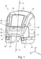
- the Fig. 1 shows a front hood 10 according to the invention of a rail vehicle carriage (not shown).
- the front hood 10 has a main element 20, a front element 30, a first cover element 41 and a second cover element 42.
- the main element 20 is made in one piece and has several areas, namely a roof area 21, a front area 22 with a front pane 25, a first side area 23 and a second side area 24.
- the areas can merge continuously or border one another with edges.
- Each area can have curved or flat surfaces.
- the main element 20 can, for example, be made of a glass fiber reinforced plastic (GRP).
- GFP glass fiber reinforced plastic
- the main element 20 can, for example, be fastened to a car body (not shown) or to a supporting structure of the rail vehicle (also not shown) and sealed with respect to this, e.g. with the aid of holder plates and screw connections (not shown) and also sealing elements (not shown).
- the front element 30 adjoins a front edge 50 of the front area 22 and is releasably attached to it.
- the front edge 50 runs predominantly in a straight line along a transverse axis y, but can also run predominantly curved or predominantly V-shaped.
- the front element 30 also adjoins the first side area 23 at a first side edge 51.
- the first side edge 51 runs in FIG Fig. 1 predominantly in a straight line along a vertical axis z, but can also run predominantly curved, stepped and / or inclined.
- the front element 30 also adjoins the second side area 24 at a second side edge 52.
- the second side edge 52 runs symmetrically to the first side edge 51 and is in Fig. 1 only partially shown.
- the front element 30 forms a first lower edge 53 with the first side area 23.
- the front element 30 forms a second lower edge 54 with the second side area 24.
- the front element 30 has a first maintenance flap 31 and a second maintenance flap 32, which can be opened and enable, for example, a filling of windshield washer fluid.
- the first maintenance flap 31 and the second maintenance flap 32 can be removable or, for example, with in Fig. 1 Hinges (not shown) can be attached to the front element 30.
- the first cover element 41 adjoins the first lower edge 53 and is releasably attached to it.
- the first cover element 41 has an opening 60 for a first energy dissipation element (not shown). Alternatively, the opening 60 can be omitted and the first energy-absorbing element can be completely covered.
- the second cover element 42 adjoins the second lower edge 54 and is releasably attached to it.
- the second cover element 42 has an opening 61 for a second energy dissipation element (not shown).
- the opening 61 can be omitted and the second energy-absorbing element can be completely covered.
- the front element 30, the main element 20, the first cover element 41 and the second cover element 42 are connected to one another with the aid of holder plates and screw connections (not shown) and sealed against one another with sealing elements (also not shown).
- the front element 30, the first cover element 41 and the second cover element 42 form an opening 62 for an in Fig. 2 Coupling 80 shown.
- an opening for the coupling 80 can only be formed by the first cover element 41 and the second cover element 42 if these adjoin one another above the coupling 80 and below the front element 30.
- a closing device 70 is arranged behind the opening 62 for the coupling 80, of which FIG Fig. 1 only one closing element 71 is shown.
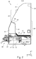
- FIG. 10 is a section through the front hood 10 along the line AA in FIG Fig. 1 shown.
- main element 20 Of the main element 20, only the roof area 21, the front area 22 and the second side area 24 as well as the second side edge 52 are shown here. Furthermore, the front element 30 and the second cover element 42 are shown.
- the terminating device 70 is arranged above the coupling 80 and the second cover element 42.
- the terminating device 70 has a flat terminating element 71 which is inclined at an angle ⁇ to the longitudinal axis x and otherwise runs in the transverse direction y.
- the terminating device 70 has a base element 72 which runs along a plane formed from the longitudinal axis x and the transverse axis y.
- the closing element 71 and the base element 72 can be made in one piece and have the same width in the transverse direction y.
- An insulating material 74 which is a thermal and / or acoustic insulating material 74, is arranged on an inner surface 73 of the terminating device 70. The insulating material 74 rests against the inner surface 73 and is in the Fig. 2 Shown with a small distance from the inner surface 73 only for reasons of better illustration.
- the closing device 70 and the first maintenance flap 31 as well as the second maintenance flap 32 are first attached to the front element 30.
- the main element 20 is then releasably fastened to the car body or to the support structure of the rail vehicle car.
- the front element 30 is then detachably attached to the main element 20.
- the first cover element 41 is detachably attached to the first lower edge 53
- the second cover element 42 is detachably attached to the second lower edge 54.
- the front element 30, the first cover element 41 and / or the second cover element 42 are damaged, only the damaged element can be replaced.
- the main element 20 can be retained.
- the closing element 71 contributes to a reduction in the generation of noise at the opening 62 for the coupling 80. This noise reduction is brought about by the arrangement of the closing element 71 inclined by the angle ⁇ .
- the insulating material 74 ensures a further reduction in noise in an area of a driver's cab area not shown in the figures. If the insulating material 74 has thermally insulating properties, temperature control of a driver's foot area is also promoted.
Landscapes
- Engineering & Computer Science (AREA)
- Life Sciences & Earth Sciences (AREA)
- Wood Science & Technology (AREA)
- Mechanical Engineering (AREA)
- Superstructure Of Vehicle (AREA)
Description
Die Erfindung betrifft eine Fronthaube für einen Schienenfahrzeugwagen, ein Verfahren zur Montage mindestens einer Fronthaube und einen Schienenfahrzeugwagen mit mindestens einer Fronthaube.The invention relates to a front hood for a rail vehicle car, a method for assembling at least one front hood and a rail vehicle car with at least one front hood.
Es ist bekannt, dass ein Endwagen eines Schienenfahrzeugs eine Fronthaube, beispielsweis aus einem Glasfaser verstärkten Kunststoff (GFK), aufweisen kann. Die Fronthaube dient zur Abdeckung des Fahrerraumbereichs und ist oft aerodynamisch günstig geformt. Dabei kann die Fronthaube selbsttragend und direkt an einem Wagenkasten des Endwagens befestigt sein. Alternativ kann die Fronthaube an einer Gerüststruktur befestigt sein, die den Fahrerraumbereich enthält. Nachteilig ist bei beiden Alternativen, dass im Fall einer Beschädigung der Fronthaube ein Austausch der gesamten Fronthaube erfolgen muss.It is known that an end car of a rail vehicle can have a front hood, for example made of a glass fiber reinforced plastic (GRP). The front hood is used to cover the driver's area and is often aerodynamically shaped. The front hood can be self-supporting and attached directly to a car body of the end car. Alternatively, the front hood can be attached to a scaffolding structure that contains the driver's compartment area. The disadvantage of both alternatives is that if the front hood is damaged, the entire front hood must be replaced.
Die Druckschrift
Die Druckschrift
Der Erfindung liegt daher die Aufgabe zu Grunde, eine Fronthaube und ein Verfahren zur Montage einer Fronthaube zu schaffen, wobei die Fronthaube bei einer Beschädigung einfach und kostengünstig wiederherstellbar ist.The invention is therefore based on the object of creating a front hood and a method for assembling a front hood, wherein the front hood can be easily and inexpensively restored in the event of damage.
Diese Aufgabe wird erfindungsgemäß mit einer Fronthaube für einen Schienenfahrzeugwagen nach Anspruch 1 gelöst. Weiterhin wird die Aufgabe mit einem Verfahren zur Montage mindestens einer Fronthaube nach Anspruch 12 und einem Schienenfahrzeugwagen mit mindestens einer Fronthaube nach Anspruch 15 gelöst. Vorteilhafte Ausgestaltungen der Erfindung sind in den Unteransprüchen enthalten.This object is achieved according to the invention with a front hood for a rail vehicle car according to claim 1. Furthermore, the object is achieved with a method for assembling at least one front hood according to claim 12 and a rail vehicle carriage with at least one front hood according to claim 15. Advantageous refinements of the invention are contained in the subclaims.
Erfindungsgemäß besteht die Lösung der Aufgabe in einer Fronthaube für einen Schienenfahrzeugwagen, wobei
- die Fronthaube ein Hauptelement mit einem Dachbereich, einem Frontbereich und zwei Seitenbereichen aufweist,
- mindestens ein Frontelement an das Hauptelement angrenzt und lösbar an dem Hauptelement befestigt ist und
- das Frontelement an Seitenkanten der Seitenbereiche angrenzt und zwischen den Seitenkanten an mindestens eine Frontkante des Frontbereichs angrenzt.
- Ein erster Seitenbereich des Hauptelements und das Frontelement bilden eine erste Unterkante aus, an die mindestens ein erstes Abdeckungselement angrenzt, das lösbar an der ersten Unterkante befestigt ist und
- ein zweiter Seitenbereich des Hauptelements und das Frontelement bilden eine zweite Unterkante aus, and die mindestens ein zweites Abdeckungselement angrenzt, das lösbar an der zweiten Unterkante befestigt ist.
- the front hood has a main element with a roof area, a front area and two side areas,
- at least one front element adjoins the main element and is releasably attached to the main element and
- the front element adjoins side edges of the side areas and adjoins at least one front edge of the front area between the side edges.
- A first side area of the main element and the front element form a first lower edge which is adjoined by at least one first cover element which is releasably attached to the first lower edge and
- a second side area of the main element and the front element form a second lower edge, which is adjoined by at least one second cover element which is releasably attached to the second lower edge.
Ein Vorteil der erfindungsgemäßen Fronthaube besteht darin, dass diese bei einer Beschädigung einfach und kostengünstig wiederherstellbar ist. Die Fronthaube weist mindestens vier Elemente auf, nämlich das Hauptelement, das Frontelement sowie das erste Abdeckungselement und das zweite Abdeckungselement. Bei einer Beschädigung kann jedes der vier Elemente unabhängig von jedem anderen Element ausgetauscht werden. Beschädigungen treten besonders oft im unteren Bereich der Fronthaube auf. Daher sind das erste Abdeckungselement und das zweite Abdeckungselement in einem unteren Bereich der Fronthaube austauschbar angeordnet. Außerdem treten Beschädigungen auch oft im Frontbereich auf, in dem sich das austauschbare Frontelement befindet. Die erste Unterkante und/oder die zweite Unterkante können einen teilweise oder vollständig geradlinigen (z.B. horizontalen), abgestuften, geneigten und/oder gekrümmten Verlauf aufweisen.One advantage of the front hood according to the invention is that it can be easily and inexpensively restored in the event of damage. The front hood has at least four elements, namely the main element, the front element and the first cover element and the second cover element. In the event of damage, each of the four elements can be replaced independently of every other element. Damage occurs particularly often in the lower area of the front hood. Hence the first Cover element and the second cover element arranged interchangeably in a lower region of the front hood. In addition, damage often occurs in the front area in which the replaceable front element is located. The first lower edge and / or the second lower edge can have a partially or completely straight (eg horizontal), stepped, inclined and / or curved course.
Gemäß einer vorteilhaften Weiterbildung der Erfindung weisen das Frontelement, das erste Abdeckungselement und das zweite Abdeckungselement jeweils geringere Außenabmessungen auf als das Hauptelement. Durch die geringeren Abmessungen sind das Frontelement, das erste Abdeckungselement und das zweite Abdeckungselement kostengünstig herstellbar.According to an advantageous development of the invention, the front element, the first cover element and the second cover element each have smaller external dimensions than the main element. Due to the smaller dimensions, the front element, the first cover element and the second cover element can be manufactured inexpensively.
Weiterhin können das erste Abdeckungselement und das zweite Abdeckungselement jeweils mindestens eine Öffnung für mindestens ein Energieverzehrelement aufweisen und/oder dass das Frontelement kann mindestens eine Wartungsklappe aufweisen. Das erste Abdeckungselement und das zweite Abdeckungselement decken unter anderem jeweils ein Energieverzehrelement ab, das auch als Energieabsorptionselement bezeichnet werden kann. Aufgrund der Öffnung kann jedes Energieverzehrelement aus dem ersten Abdeckungselement und dem zweiten Abdeckungselement herausragen und eine Aufprallenergie abfangen, bevor ein Element der Fronthaube beschädigt wird. Eine Wartungsklappe ermöglicht einen einfachen Zugang zu einem Innenraum der Fronthaube, z.B. bei einem Befüllen von Scheibenwischwasser.Furthermore, the first cover element and the second cover element can each have at least one opening for at least one energy dissipation element and / or the front element can have at least one maintenance flap. The first cover element and the second cover element each cover, among other things, an energy-absorbing element, which can also be referred to as an energy-absorbing element. Because of the opening, each energy-absorbing element can protrude from the first cover element and the second cover element and absorb impact energy before an element of the front hood is damaged. A maintenance flap enables easy access to an interior of the front hood, e.g. when filling windshield washer fluid.
In einer zweckmäßigen Weiterbildung der Erfindung können das Frontelement, das erste Abdeckungselement und das zweite Abdeckungselement oder nur das erste Abdeckungselement und das zweite Abdeckungselement eine Öffnung für eine Kupplung ausbilden. Die Öffnung ermöglicht einen Zugang zur Kupplung, wobei auf Bugklappen verzichtet wird. Die Öffnung begünstigt also eine einfache Bauweise der Fronthaube.In an expedient development of the invention, the front element, the first cover element and the second cover element or only the first cover element and the second cover element can form an opening for a coupling. The opening allows access to the coupling without the need for front flaps. The opening thus favors a simple design of the front hood.
In einer besonderen Ausgestaltung der Erfindung begrenzt eine Abschlussvorrichtung die Fronthaube nach unten. Dadurch wird ein Innenraum der Fronthaube vor Schmutz und Beschädigungen, z.B. durch Schotterflug, geschützt. Außerdem kann die Abschlussvorrichtung ein aerodynamisches Verhalten in einem unteren Bereich der Fronthaube verbessern.In a special embodiment of the invention, a closing device delimits the front hood downwards. This protects the interior of the front hood from dirt and damage, e.g. by flying gravel, protected. In addition, the closing device can improve aerodynamic behavior in a lower area of the front hood.
Vorzugsweise ist die Abschlussvorrichtung hinter der Öffnung für die Kupplung angeordnet. An der Öffnung für die Kupplung ergibt sich während der Fahrt eine Luftströmung, die Schwingungen und damit eine Geräuschentwicklung erzeugt. Die Abschlussvorrichtung kann diese Schwingung abdämpfen und die Geräuschentwicklung verringern.The terminating device is preferably arranged behind the opening for the coupling. At the opening for the clutch, there is an air flow while driving, which generates vibrations and thus noise. The closing device can dampen this oscillation and reduce the development of noise.
Insbesondere ist die Abschlussvorrichtung lösbar an dem Frontelement oder an dem ersten Abdeckungselement und dem zweiten Abdeckungselement befestigt. Wenn die Öffnung für die Kupplung oben von dem Frontelement begrenzt wird, kann die Abschlussvorrichtung direkt an dem Frontelement befestigt werden. Wenn die Öffnung für die Kupplung oben von dem ersten Abdeckungselement und dem zweiten Abdeckungselement begrenzt wird, kann die Abschlussvorrichtung direkt an dem ersten Abdeckungselement und dem zweiten Abdeckungselement befestigt werden. Dadurch wird eine einfache Befestigungsanordnung ermöglicht.In particular, the terminating device is releasably attached to the front element or to the first cover element and the second cover element. If the opening for the coupling is limited at the top by the front element, the closing device can be attached directly to the front element. If the opening for the coupling is delimited at the top by the first cover element and the second cover element, the terminating device can be attached directly to the first cover element and the second cover element. This enables a simple fastening arrangement.
Außerdem kann die Abschlussvorrichtung mindestens ein Abschlusselement aufweisen, das um einen Winkel α zu einer Längsachse der Fronthaube geneigt ist. Das geneigte Abschlusselement kann zu einer Verringerung von Schwingungen beitragen und damit eine Geräuschentwicklung vermindern.In addition, the terminating device can have at least one terminating element which is inclined at an angle α to a longitudinal axis of the front hood. The inclined closing element can contribute to a reduction in vibrations and thus reduce the development of noise.
Weiterhin kann ein Werkstoff der Abschlussvorrichtung günstigere akustische Eigenschaften aufweisen als ein Werkstoff der Fronthaube. Die akustischen Eigenschaften der Abschlussvorrichtung tragen vorteilhaft zu einer Geräuschverminderung bei.Furthermore, a material of the closing device can have more favorable acoustic properties than a material of the front hood. The acoustic properties of the terminating device contribute advantageously to a reduction in noise.
Zusätzlich kann mindestens ein Isoliermaterial auf mindestens einer Innenfläche der Abschlussvorrichtung angebracht sein. Das Isoliermaterial trägt ebenfalls zur Geräuschverminderung bei. Das Isoliermaterial kann zusätzlich auch thermisch isolierende Eigenschaften aufweisen.In addition, at least one insulating material can be applied to at least one inner surface of the terminating device. The insulating material also helps to reduce noise. The insulating material can also have thermally insulating properties.
Speziell kann das Abschlusselement einen Stahlwerkstoff und eine erste Dicke von 2 mm einschließlich eines vorgegebenen Toleranzbereichs aufweisen und/oder das Isoliermaterial Mineralwolle und eine zweite Dicke von 60 mm einschließlich eines vorgegebenen Toleranzbereichs aufweisen. Die erste Dicke und die zweite Dicke sind dabei unter Berücksichtigung von Werkstoffeigenschaften auf einander abgestimmt.In particular, the closing element can have a steel material and a first thickness of 2 mm including a predetermined tolerance range and / or the insulating material can have mineral wool and a second thickness of 60 mm including a predetermined tolerance range. The first thickness and the second thickness are matched to one another, taking into account material properties.
Weiterhin besteht die Lösung der Aufgabe in einem Verfahren zur Montage mindestens einer Fronthaube, dadurch gekennzeichnet, dass die folgenden Schritte erfolgen:
- a) Montage des Hauptelements an einer Struktur des Schienenfahrzeugwagens
- b) Montage des Frontelements an dem Hauptelement,
- c) Montage des ersten Abdeckungselements und des zweiten Abdeckungselements an dem Frontelement und dem Hauptelement.
- a) Mounting the main element on a structure of the rail vehicle car
- b) assembly of the front element on the main element,
- c) mounting the first cover element and the second cover element on the front element and the main element.
Ein Vorteil des erfindungsgemäßen Verfahrens besteht darin, dass die Montage in wenigen Schritten erfolgen kann und daher kostensparend ist. Eine Demontage bzw. ein Austausch eines einzelnen Elements ist ebenfalls einfach möglich, indem z.B. nur das Frontelement, nur das erste Abdeckungselement oder nur das zweite Abdeckungselement entfernt und ausgetauscht wird. Selbstverständlich kann auch mehr als ein Element entfernt und ausgetauscht werden.One advantage of the method according to the invention is that the assembly can take place in a few steps and is therefore cost-saving. A dismantling or replacement of an individual element is also easily possible, e.g. by removing and replacing only the front element, only the first cover element or only the second cover element. Of course, more than one element can be removed and replaced.
Außerdem kann vor Schritt a) eine Montage einer Abschlussvorrichtung an dem Frontelement erfolgen oder nach Schritt c) kann eine Montage einer Abschlussvorrichtung an dem Frontelement oder an dem ersten Abdeckungselement und dem zweiten Abdeckungselement erfolgen. Die Montagereihenfolge für die Abschlussvorrichtung ist somit variabel und kann an die Elemente angepasst werden, die die Öffnung für die Kupplung bilden.In addition, a terminating device can be installed on the front element before step a) or a terminating device can be installed on the front element or on the first cover element and the second cover element after step c). The assembly sequence for the closing device is thus variable and can be adapted to the elements that form the opening for the coupling.
Weiterhin kann vor oder nach Schritt b) eine Montage von Wartungsklappen an dem Frontelement erfolgen. Die Montagereihenfolge für die Wartungsklappen ist somit ebenfalls variabel. Bei Beschädigung einer Wartungsklappe allein, kann diese auch einzeln ausgetauscht werden.Furthermore, maintenance flaps can be installed on the front element before or after step b). The assembly sequence for the maintenance hatches is thus also variable. If only one maintenance flap is damaged, it can also be replaced individually.
Die Aufgabe wird auch durch einen Schienenfahrzeugwagen mit mindestens einer Fronthaube gelöst. Die Fronthaube kann an einem Wagenkasten und/oder an einer Tragstruktur des Schienenfahrzeugwagens befestigt sein.The object is also achieved by a rail vehicle car with at least one front hood. The front hood can be attached to a car body and / or to a support structure of the rail vehicle car.
Im Folgenden wird ein Ausführungsbeispiel der Erfindung anhand von zwei Figuren näher erläutert. Es zeigen:
- Fig. 1
- eine perspektivische Ansicht einer erfindungsgemäßen Fronthaube und
- Fig. 2
- einen Längsschnitt durch die erfindungsgemäße Fronthaube entlang der Linie A-A in
Fig. 1 .
- Fig. 1
- a perspective view of a front hood according to the invention and
- Fig. 2
- a longitudinal section through the front hood according to the invention along the line AA in
Fig. 1 .
Die
Das Hauptelement 20 ist einstückig ausgeführt und weist mehrere Bereiche auf, nämlich einen Dachbereich 21, einen Frontbereich 22 mit einer Frontscheibe 25, einen ersten Seitenbereich 23 und einen zweiten Seitenbereich 24 auf. Die Bereiche können kontinuierlich ineinander übergehen oder kantig aneinander angrenzen. Jeder Bereich kann gewölbte oder ebene Teilflächen aufweisen. Das Hauptelement 20 kann z.B. aus einem Glasfaser verstärkten Kunststoff (GFK) hergestellt. Das Hauptelement 20 kann z.B. an einem nicht dargestellten Wagenkasten oder an einer ebenfalls nicht dargestellten Tragstruktur des Schienenfahrzeugs befestigt und gegenüber dieser abgedichtet sein, z.B. mit Hilfe von nicht dargestellten Halterplatten und Schraubenverbindungen sowie ebenfalls nicht dargestellten Dichtungselementen.The
Das Frontelement 30 grenzt an eine Frontkante 50 des Frontbereichs 22 an und ist lösbar an dieser befestigt. Die Frontkante 50 verläuft überwiegend geradlinig entlang einer Querachse y, kann jedoch auch überwiegend gekrümmt oder überwiegend V-förmig verlaufen.The
Das Frontelement 30 grenzt weiterhin an einer ersten Seitenkante 51 an den ersten Seitenbereich 23 an. Die erste Seitenkante 51 verläuft in
Das Frontelement 30 weist eine erste Wartungsklappe 31 und eine zweite Wartungsklappe 32 auf, die geöffnet werden können und z.B. eine Befüllung von Scheibenwischwasser ermöglichen. Die erste Wartungsklappe 31 und die zweite Wartungsklappe 32 können abnehmbar sein oder z.B. mit in
Das erste Abdeckungselement 41 grenzt an die erste Unterkante 53 an und ist lösbar an dieser befestigt. Das erste Abdeckungselement 41 weist eine Öffnung 60 für ein nicht dargestelltes erstes Energieverzehrelement auf. Alternativ kann die Öffnung 60 entfallen und das erste Energieverzehrelement vollständig abgedeckt sein.The
Das zweite Abdeckungselement 42 grenzt an die zweite Unterkante 54 an und ist lösbar an dieser befestigt. Das zweite Abdeckungselement 42 weist eine Öffnung 61 für ein nicht dargestelltes zweites Energieverzehrelement auf. Alternativ kann die Öffnung 61 entfallen und das zweite Energieverzehrelement vollständig abgedeckt sein.The
Das Frontelement 30, das Hauptelement 20, das erste Abdeckungselement 41 und das zweite Abdeckungselement 42 sind untereinander jeweils mit Hilfe von nicht dargestellten Halterplatten und Schraubenverbindungen verbunden und mit ebenfalls nicht dargestellten Dichtungselementen gegeneinander abgedichtet.The
Das Frontelement 30, das erste Abdeckungselement 41 und das zweite Abdeckungselement 42 bilden eine Öffnung 62 für eine in
In
Die Abschlussvorrichtung 70 weist ein flächiges Abschlusselement 71 auf, das um einen Winkel α zur Längsachse x geneigt ist und ansonsten in der Querrichtung y verläuft. Außerdem weist die Abschlussvorrichtung 70 ein Bodenelement 72 auf, das entlang einer aus der Längsachse x und der Querachse y gebildeten Ebene verläuft. Das Abschlusselement 71 und das Bodenelement 72 können einstückig ausgeführt und in der Querrichtung y gleich breit sein. Auf einer Innenfläche 73 der Abschlussvorrichtung 70 ist ein Isoliermaterial 74 angeordnet, das ein thermisches und/oder akustisches Isoliermaterial 74 ist. Das Isoliermaterial 74 liegt an der Innenfläche 73 an und ist in der
Bei der Montage werden zunächst die Abschlussvorrichtung 70 und die erste Wartungsklappe 31 sowie die zweite Wartungsklappe 32 an dem Frontelement 30 befestigt. Anschließend wird das Hauptelement 20 lösbar an dem Wagenkasten oder an der Tragstruktur des Schienenfahrzeugwagens befestigt. Danach wird das Frontelement 30 lösbar an dem Hauptelement 20 befestigt. Zum Schluss wird das erste Abdeckungselement 41 lösbar an der ersten Unterkante 53 befestigt, und das zweite Abdeckungselement 42 wird lösbar an der zweiten Unterkante 54 befestigt.During assembly, the closing
Im Betrieb kann bei einer Beschädigung des Frontelements 30, des ersten Abdeckungselements 41 und/oder des zweiten Abdeckungselements 42 jeweils nur das beschädigte Element ausgetauscht werden. Das Hauptelement 20 kann beibehalten werden.In operation, if the
Außerdem trägt das Abschlusselement 71 zu einer Verringerung der Geräuschbildung an der Öffnung 62 für die Kupplung 80 bei. Diese Geräuschverringerung wird durch die um den Winkel α geneigte Anordnung des Abschlusselements 71 bewirkt. Das Isoliermaterial 74 sorgt für eine weitergehende Geräuschminderung in einem Bereich eines in den Figuren nicht dargestellten Führerraumbereichs. Wenn das Isoliermaterial 74 thermisch isolierende Eigenschaften aufweist, wird außerdem eine Temperierung eines Fußbereichs eines Fahrers begünstigt.In addition, the closing
- 1010
- FronthaubeFront hood
- 2020th
- HauptelementMain element
- 2121
- DachbereichRoof area
- 2222nd
- FrontbereichFront area
- 2323
- Erster SeitenbereichFirst page area
- 2424
- Zweiter SeitenbereichSecond side area
- 2525th
- FrontscheibeWindshield
- 3030th
- FrontelementFront element
- 3131
- Erste WartungsklappeFirst maintenance hatch
- 3232
- Zweite WartungsklappeSecond maintenance hatch
- 4141
- Erstes AbdeckungselementFirst cover element
- 4242
- Zweites AbdeckungselementSecond cover element
- 5050
- FrontkanteFront edge
- 5151
- Erste SeitenkanteFirst side edge
- 5252
- Zweite SeitenkanteSecond side edge
- 5353
- Erste UnterkanteFirst lower edge
- 5454
- Zweite UnterkanteSecond lower edge
- 6060
- Öffnungopening
- 6161
- Öffnungopening
- 6262
- Öffnungopening
- 7070
- AbschlussvorrichtungClosing device
- 7171
- AbschlusselementFinishing element
- 7272
- BodenelementFloor element
- 7373
- InnenflächeInner surface
- 7474
- Isoliermaterialinsulating material
- 8080
- Kupplungcoupling
- xx
- LängsachseLongitudinal axis
- yy
- QuerachseTransverse axis
- zz
- Senkrechte AchseVertical axis
- αα
- Winkelangle
Claims (15)
- Front cap (10) for a rail vehicle car, wherein- the front cap (10) comprises a main member (20) having a roof portion (21), a front portion (22) and two side portions (23, 24)- at least one front member (30) is adjoining the main member (20), and- the front member (30) adjoins side edges (51, 52) of the side portions (23, 24) and adjoins at least one front edge (50) of the front portion (22) between the side edges (51, 52),- a first side portion (23) of the main member (20) and the front member (30) form a first lower edge (53) adjoining at least a first cover member (41), and- a second side portion (24) of the main member (20) and the front member (30) form a second lower edge (54) adjoined by at least one second cover member (42),- characterised in that- the front member (30) is removably attached to the main member (20),- the first cover member (41) is removably attached to the first lower edge (53), and- the second cover member (42) is removably attached to the second lower edge (54).
- Front cap (10) according to claim 1, characterized in that the front member (30), the first cover member (41) and the second cover member (42) each comprise smaller outer dimensions than the main member (20).
- Front cap (10) according to one of the preceding claims, characterized in that the first cover member (41) and the second cover member (42) each comprise at least one opening (60, 61) for at least one energy absorption member and/or that the front member (30) comprises at least one maintenance flap (31, 32).
- Front cap (10) according to one of the preceding claims, characterized in that the front member (30), the first cover member (41) and the second cover member (42) or only the first cover member (41) and the second cover member (42) form an opening (62) for a coupling (80).
- Front cap (10) according to one of the preceding claims, characterised in that a closing device (70) bounds the front cap (10) downwards.
- Front cap (10) according to claims 4 and 5, characterised in that the closing device (70) is arranged behind the opening (62) for the coupling (80).
- Front cap (10) according to claim 5 or 6, characterised in that the closing device (70) is removably attached to the front member (30) or to the first cover member (41) and the second cover member (42).
- Front cap (10) according to one of the claims 5 to 7, characterized in that the closing device (70) comprises at least one closing element (71) which is inclined by an angle (α) to a longitudinal axis (x) of the front cap (10).
- Front cap (10) according to one of the claims 5 to 8, characterized in that a material of the closing device (70) comprises more favourable acoustic properties than a material of the front cap (10).
- Front cap (10) according to any one of claims 5 to 9, characterized in that at least one insulating material (74) is applied to at least one inner surface (73) of the closing device (70).
- Front cap (10) according to any one of claims 8 to 10, characterized in that the closing element (71) comprises a steel material and a first thickness of 2 mm including a predetermined tolerance range and/or the insulating material (74) comprises mineral wool and a second thickness of 60 mm including a predetermined tolerance range.
- Method of mounting at least one front cap (10) according to any one of claims 1 to 11 on a rail vehicle, characterized in that the following steps are performed:(a) mounting the main member (20) on a structure of the rail vehicle car(b) mounting the front member (30) to the main member (20),(c) mounting the first cover member (41) and the second cover member (42) to the front member (30) and the main member (20).
- Method according to claim 12, characterized in that before step (a) a closing device (70) is mounted on the front member (30) or after step (c) a closing device (70) is mounted on the front member (30), the first cover member (41) and/or the second cover member (42).
- Method according to claim 13, characterized in that before or after step (b) a maintenance flaps (31, 32) are mounted on the front member (30).
- Rail vehicle car with at least one front cap (10) according to one of the claims 1 to 11.
Priority Applications (2)
| Application Number | Priority Date | Filing Date | Title |
|---|---|---|---|
| PL19169255T PL3556633T3 (en) | 2018-04-18 | 2019-04-15 | Hood for a rail vehicle car, method for mounting at least one hood and rail vehicle car with at least one hood |
| SI201930174T SI3556633T1 (en) | 2018-04-18 | 2019-04-15 | Hood for a rail vehicle car, method for mounting at least one hood and rail vehicle car with at least one hood |
Applications Claiming Priority (1)
| Application Number | Priority Date | Filing Date | Title |
|---|---|---|---|
| DE102018109236.9A DE102018109236A1 (en) | 2018-04-18 | 2018-04-18 | Front hood for a rail vehicle car, method for assembling at least one front hood and rail vehicle car with at least one front hood |
Publications (2)
| Publication Number | Publication Date |
|---|---|
| EP3556633A1 EP3556633A1 (en) | 2019-10-23 |
| EP3556633B1 true EP3556633B1 (en) | 2021-11-17 |
Family
ID=66217704
Family Applications (1)
| Application Number | Title | Priority Date | Filing Date |
|---|---|---|---|
| EP19169255.7A Active EP3556633B1 (en) | 2018-04-18 | 2019-04-15 | Hood for a rail vehicle car, method for mounting at least one hood and rail vehicle car with at least one hood |
Country Status (4)
| Country | Link |
|---|---|
| EP (1) | EP3556633B1 (en) |
| DE (1) | DE102018109236A1 (en) |
| PL (1) | PL3556633T3 (en) |
| SI (1) | SI3556633T1 (en) |
Families Citing this family (1)
| Publication number | Priority date | Publication date | Assignee | Title |
|---|---|---|---|---|
| CN113306581B (en) * | 2021-06-11 | 2022-11-22 | 中车青岛四方机车车辆股份有限公司 | Fixed cover, hood and rail vehicle |
Family Cites Families (6)
| Publication number | Priority date | Publication date | Assignee | Title |
|---|---|---|---|---|
| US8375869B2 (en) * | 2008-03-12 | 2013-02-19 | Siemens Ag Österreich | Crash-resistant front apron for a rail vehicle |
| CN203592984U (en) | 2013-11-08 | 2014-05-14 | 青岛罗美威奥新材料制造有限公司 | Rail train integrated train head structure |
| DE102014212945A1 (en) * | 2014-07-03 | 2016-01-21 | Siemens Aktiengesellschaft | track vehicle |
| DE102016205305A1 (en) * | 2016-03-31 | 2017-10-05 | Siemens Aktiengesellschaft | Rail vehicle, in particular locomotive |
| DE102016112207A1 (en) * | 2016-07-04 | 2018-01-04 | Bombardier Transportation Gmbh | Exterior trim element for a vehicle |
| CN206983990U (en) * | 2017-06-27 | 2018-02-09 | 青岛欧特美交通装备有限公司 | A kind of rail vehicle and its drivers' cab head-mounting device |
-
2018
- 2018-04-18 DE DE102018109236.9A patent/DE102018109236A1/en active Pending
-
2019
- 2019-04-15 EP EP19169255.7A patent/EP3556633B1/en active Active
- 2019-04-15 SI SI201930174T patent/SI3556633T1/en unknown
- 2019-04-15 PL PL19169255T patent/PL3556633T3/en unknown
Also Published As
| Publication number | Publication date |
|---|---|
| SI3556633T1 (en) | 2022-03-31 |
| PL3556633T3 (en) | 2022-03-07 |
| EP3556633A1 (en) | 2019-10-23 |
| DE102018109236A1 (en) | 2019-10-24 |
Similar Documents
| Publication | Publication Date | Title |
|---|---|---|
| EP1336551B1 (en) | Wheel guard assembly for a vehicle | |
| DE102015112506A1 (en) | front end module | |
| DE102017129199B4 (en) | Airflow management system for a vehicle | |
| DE3840214A1 (en) | AIR INLET HOUSING FOR A MOTOR VEHICLE | |
| EP3442834B1 (en) | Vehicle skirt consisting of several sections | |
| WO2018162284A1 (en) | Hinge assembly for a bonnet of a motor vehicle, and motor vehicle | |
| DE102008006103A1 (en) | motor vehicle | |
| DE102010020304A1 (en) | subcarrier | |
| DE102014009943A1 (en) | The vehicle body front part structure | |
| DE102006029921A1 (en) | Vehicle with a windscreen cross member for a windshield | |
| EP2918473B1 (en) | Vehicle header module for a railborne vehicle, in particular rail vehicle having a reinforced frame structure for the front panel and front panel for the vehicle header module | |
| DE102008034038A1 (en) | Reinforcement structure for side door of motor vehicle, has reinforcement element extending over partial height for increasing buckling strength in vertical direction of door, and side impact protection element | |
| DE102024126251A1 (en) | Vehicle body structure | |
| DE102010006976A1 (en) | Motor vehicle front end | |
| EP3556633B1 (en) | Hood for a rail vehicle car, method for mounting at least one hood and rail vehicle car with at least one hood | |
| EP3495227B1 (en) | Transition to be mounted between two vehicles with a jointed connection | |
| DE102018124490B4 (en) | STRUCTURE OF A VEHICLE FRONT | |
| EP0858943A1 (en) | Motor vehicle with a connecting structure between a cross member and a firewall | |
| EP1081024A2 (en) | Front structure of a vehicle in the cowl area | |
| DE102016210004A1 (en) | Vehicle, in particular rail vehicle | |
| DE102024105564B3 (en) | Underrun protection | |
| EP0235635B1 (en) | Beam member for the front end of a vehicle | |
| EP2655157B1 (en) | Carriage body with a plastic moulded head part | |
| DE102020118750B4 (en) | Wheel arch of a motor vehicle | |
| DE102019133503B4 (en) | Crash management system |
Legal Events
| Date | Code | Title | Description |
|---|---|---|---|
| PUAI | Public reference made under article 153(3) epc to a published international application that has entered the european phase |
Free format text: ORIGINAL CODE: 0009012 |
|
| STAA | Information on the status of an ep patent application or granted ep patent |
Free format text: STATUS: THE APPLICATION HAS BEEN PUBLISHED |
|
| AK | Designated contracting states |
Kind code of ref document: A1 Designated state(s): AL AT BE BG CH CY CZ DE DK EE ES FI FR GB GR HR HU IE IS IT LI LT LU LV MC MK MT NL NO PL PT RO RS SE SI SK SM TR |
|
| AX | Request for extension of the european patent |
Extension state: BA ME |
|
| STAA | Information on the status of an ep patent application or granted ep patent |
Free format text: STATUS: REQUEST FOR EXAMINATION WAS MADE |
|
| 17P | Request for examination filed |
Effective date: 20200420 |
|
| RBV | Designated contracting states (corrected) |
Designated state(s): AL AT BE BG CH CY CZ DE DK EE ES FI FR GB GR HR HU IE IS IT LI LT LU LV MC MK MT NL NO PL PT RO RS SE SI SK SM TR |
|
| GRAP | Despatch of communication of intention to grant a patent |
Free format text: ORIGINAL CODE: EPIDOSNIGR1 |
|
| STAA | Information on the status of an ep patent application or granted ep patent |
Free format text: STATUS: GRANT OF PATENT IS INTENDED |
|
| INTG | Intention to grant announced |
Effective date: 20210621 |
|
| GRAS | Grant fee paid |
Free format text: ORIGINAL CODE: EPIDOSNIGR3 |
|
| GRAA | (expected) grant |
Free format text: ORIGINAL CODE: 0009210 |
|
| STAA | Information on the status of an ep patent application or granted ep patent |
Free format text: STATUS: THE PATENT HAS BEEN GRANTED |
|
| AK | Designated contracting states |
Kind code of ref document: B1 Designated state(s): AL AT BE BG CH CY CZ DE DK EE ES FI FR GB GR HR HU IE IS IT LI LT LU LV MC MK MT NL NO PL PT RO RS SE SI SK SM TR |
|
| REG | Reference to a national code |
Ref country code: GB Ref legal event code: FG4D Free format text: NOT ENGLISH |
|
| REG | Reference to a national code |
Ref country code: IE Ref legal event code: FG4D Free format text: LANGUAGE OF EP DOCUMENT: GERMAN |
|
| REG | Reference to a national code |
Ref country code: DE Ref legal event code: R096 Ref document number: 502019002751 Country of ref document: DE |
|
| REG | Reference to a national code |
Ref country code: AT Ref legal event code: REF Ref document number: 1447816 Country of ref document: AT Kind code of ref document: T Effective date: 20211215 |
|
| REG | Reference to a national code |
Ref country code: FI Ref legal event code: FGE |
|
| REG | Reference to a national code |
Ref country code: NO Ref legal event code: T2 Effective date: 20211117 |
|
| REG | Reference to a national code |
Ref country code: SE Ref legal event code: TRGR |
|
| REG | Reference to a national code |
Ref country code: LT Ref legal event code: MG9D |
|
| REG | Reference to a national code |
Ref country code: NL Ref legal event code: MP Effective date: 20211117 |
|
| PG25 | Lapsed in a contracting state [announced via postgrant information from national office to epo] |
Ref country code: RS Free format text: LAPSE BECAUSE OF FAILURE TO SUBMIT A TRANSLATION OF THE DESCRIPTION OR TO PAY THE FEE WITHIN THE PRESCRIBED TIME-LIMIT Effective date: 20211117 Ref country code: LT Free format text: LAPSE BECAUSE OF FAILURE TO SUBMIT A TRANSLATION OF THE DESCRIPTION OR TO PAY THE FEE WITHIN THE PRESCRIBED TIME-LIMIT Effective date: 20211117 Ref country code: BG Free format text: LAPSE BECAUSE OF FAILURE TO SUBMIT A TRANSLATION OF THE DESCRIPTION OR TO PAY THE FEE WITHIN THE PRESCRIBED TIME-LIMIT Effective date: 20220217 |
|
| PG25 | Lapsed in a contracting state [announced via postgrant information from national office to epo] |
Ref country code: IS Free format text: LAPSE BECAUSE OF FAILURE TO SUBMIT A TRANSLATION OF THE DESCRIPTION OR TO PAY THE FEE WITHIN THE PRESCRIBED TIME-LIMIT Effective date: 20220317 Ref country code: PT Free format text: LAPSE BECAUSE OF FAILURE TO SUBMIT A TRANSLATION OF THE DESCRIPTION OR TO PAY THE FEE WITHIN THE PRESCRIBED TIME-LIMIT Effective date: 20220317 Ref country code: NL Free format text: LAPSE BECAUSE OF FAILURE TO SUBMIT A TRANSLATION OF THE DESCRIPTION OR TO PAY THE FEE WITHIN THE PRESCRIBED TIME-LIMIT Effective date: 20211117 Ref country code: LV Free format text: LAPSE BECAUSE OF FAILURE TO SUBMIT A TRANSLATION OF THE DESCRIPTION OR TO PAY THE FEE WITHIN THE PRESCRIBED TIME-LIMIT Effective date: 20211117 Ref country code: HR Free format text: LAPSE BECAUSE OF FAILURE TO SUBMIT A TRANSLATION OF THE DESCRIPTION OR TO PAY THE FEE WITHIN THE PRESCRIBED TIME-LIMIT Effective date: 20211117 Ref country code: GR Free format text: LAPSE BECAUSE OF FAILURE TO SUBMIT A TRANSLATION OF THE DESCRIPTION OR TO PAY THE FEE WITHIN THE PRESCRIBED TIME-LIMIT Effective date: 20220218 Ref country code: ES Free format text: LAPSE BECAUSE OF FAILURE TO SUBMIT A TRANSLATION OF THE DESCRIPTION OR TO PAY THE FEE WITHIN THE PRESCRIBED TIME-LIMIT Effective date: 20211117 |
|
| PG25 | Lapsed in a contracting state [announced via postgrant information from national office to epo] |
Ref country code: SM Free format text: LAPSE BECAUSE OF FAILURE TO SUBMIT A TRANSLATION OF THE DESCRIPTION OR TO PAY THE FEE WITHIN THE PRESCRIBED TIME-LIMIT Effective date: 20211117 Ref country code: SK Free format text: LAPSE BECAUSE OF FAILURE TO SUBMIT A TRANSLATION OF THE DESCRIPTION OR TO PAY THE FEE WITHIN THE PRESCRIBED TIME-LIMIT Effective date: 20211117 Ref country code: RO Free format text: LAPSE BECAUSE OF FAILURE TO SUBMIT A TRANSLATION OF THE DESCRIPTION OR TO PAY THE FEE WITHIN THE PRESCRIBED TIME-LIMIT Effective date: 20211117 Ref country code: EE Free format text: LAPSE BECAUSE OF FAILURE TO SUBMIT A TRANSLATION OF THE DESCRIPTION OR TO PAY THE FEE WITHIN THE PRESCRIBED TIME-LIMIT Effective date: 20211117 Ref country code: DK Free format text: LAPSE BECAUSE OF FAILURE TO SUBMIT A TRANSLATION OF THE DESCRIPTION OR TO PAY THE FEE WITHIN THE PRESCRIBED TIME-LIMIT Effective date: 20211117 Ref country code: CZ Free format text: LAPSE BECAUSE OF FAILURE TO SUBMIT A TRANSLATION OF THE DESCRIPTION OR TO PAY THE FEE WITHIN THE PRESCRIBED TIME-LIMIT Effective date: 20211117 |
|
| REG | Reference to a national code |
Ref country code: DE Ref legal event code: R097 Ref document number: 502019002751 Country of ref document: DE |
|
| PLBE | No opposition filed within time limit |
Free format text: ORIGINAL CODE: 0009261 |
|
| STAA | Information on the status of an ep patent application or granted ep patent |
Free format text: STATUS: NO OPPOSITION FILED WITHIN TIME LIMIT |
|
| 26N | No opposition filed |
Effective date: 20220818 |
|
| PG25 | Lapsed in a contracting state [announced via postgrant information from national office to epo] |
Ref country code: AL Free format text: LAPSE BECAUSE OF FAILURE TO SUBMIT A TRANSLATION OF THE DESCRIPTION OR TO PAY THE FEE WITHIN THE PRESCRIBED TIME-LIMIT Effective date: 20211117 |
|
| REG | Reference to a national code |
Ref country code: BE Ref legal event code: MM Effective date: 20220430 |
|
| PG25 | Lapsed in a contracting state [announced via postgrant information from national office to epo] |
Ref country code: MC Free format text: LAPSE BECAUSE OF FAILURE TO SUBMIT A TRANSLATION OF THE DESCRIPTION OR TO PAY THE FEE WITHIN THE PRESCRIBED TIME-LIMIT Effective date: 20211117 Ref country code: LU Free format text: LAPSE BECAUSE OF NON-PAYMENT OF DUE FEES Effective date: 20220415 |
|
| PG25 | Lapsed in a contracting state [announced via postgrant information from national office to epo] |
Ref country code: BE Free format text: LAPSE BECAUSE OF NON-PAYMENT OF DUE FEES Effective date: 20220430 |
|
| PG25 | Lapsed in a contracting state [announced via postgrant information from national office to epo] |
Ref country code: IE Free format text: LAPSE BECAUSE OF NON-PAYMENT OF DUE FEES Effective date: 20220415 |
|
| PG25 | Lapsed in a contracting state [announced via postgrant information from national office to epo] |
Ref country code: IT Free format text: LAPSE BECAUSE OF FAILURE TO SUBMIT A TRANSLATION OF THE DESCRIPTION OR TO PAY THE FEE WITHIN THE PRESCRIBED TIME-LIMIT Effective date: 20211117 |
|
| P01 | Opt-out of the competence of the unified patent court (upc) registered |
Effective date: 20230822 |
|
| REG | Reference to a national code |
Ref country code: FI Ref legal event code: PCE Owner name: ALSTOM HOLDINGS |
|
| PG25 | Lapsed in a contracting state [announced via postgrant information from national office to epo] |
Ref country code: HU Free format text: LAPSE BECAUSE OF FAILURE TO SUBMIT A TRANSLATION OF THE DESCRIPTION OR TO PAY THE FEE WITHIN THE PRESCRIBED TIME-LIMIT; INVALID AB INITIO Effective date: 20190415 |
|
| PG25 | Lapsed in a contracting state [announced via postgrant information from national office to epo] |
Ref country code: MK Free format text: LAPSE BECAUSE OF FAILURE TO SUBMIT A TRANSLATION OF THE DESCRIPTION OR TO PAY THE FEE WITHIN THE PRESCRIBED TIME-LIMIT Effective date: 20211117 Ref country code: CY Free format text: LAPSE BECAUSE OF FAILURE TO SUBMIT A TRANSLATION OF THE DESCRIPTION OR TO PAY THE FEE WITHIN THE PRESCRIBED TIME-LIMIT Effective date: 20211117 |
|
| PG25 | Lapsed in a contracting state [announced via postgrant information from national office to epo] |
Ref country code: MT Free format text: LAPSE BECAUSE OF FAILURE TO SUBMIT A TRANSLATION OF THE DESCRIPTION OR TO PAY THE FEE WITHIN THE PRESCRIBED TIME-LIMIT Effective date: 20211117 |
|
| PGFP | Annual fee paid to national office [announced via postgrant information from national office to epo] |
Ref country code: SI Payment date: 20250403 Year of fee payment: 7 |
|
| PGFP | Annual fee paid to national office [announced via postgrant information from national office to epo] |
Ref country code: FI Payment date: 20250424 Year of fee payment: 7 |
|
| PGFP | Annual fee paid to national office [announced via postgrant information from national office to epo] |
Ref country code: PL Payment date: 20250403 Year of fee payment: 7 Ref country code: DE Payment date: 20250422 Year of fee payment: 7 |
|
| PGFP | Annual fee paid to national office [announced via postgrant information from national office to epo] |
Ref country code: GB Payment date: 20250423 Year of fee payment: 7 |
|
| PGFP | Annual fee paid to national office [announced via postgrant information from national office to epo] |
Ref country code: NO Payment date: 20250424 Year of fee payment: 7 |
|
| PGFP | Annual fee paid to national office [announced via postgrant information from national office to epo] |
Ref country code: FR Payment date: 20250425 Year of fee payment: 7 |
|
| PGFP | Annual fee paid to national office [announced via postgrant information from national office to epo] |
Ref country code: CH Payment date: 20250501 Year of fee payment: 7 |
|
| PGFP | Annual fee paid to national office [announced via postgrant information from national office to epo] |
Ref country code: AT Payment date: 20250423 Year of fee payment: 7 |
|
| PGFP | Annual fee paid to national office [announced via postgrant information from national office to epo] |
Ref country code: SE Payment date: 20250429 Year of fee payment: 7 |
|
| PG25 | Lapsed in a contracting state [announced via postgrant information from national office to epo] |
Ref country code: TR Free format text: LAPSE BECAUSE OF FAILURE TO SUBMIT A TRANSLATION OF THE DESCRIPTION OR TO PAY THE FEE WITHIN THE PRESCRIBED TIME-LIMIT Effective date: 20211117 |