EP3554929B1 - Chenille, en particulier chenille en caoutchouc - Google Patents
Chenille, en particulier chenille en caoutchouc Download PDFInfo
- Publication number
- EP3554929B1 EP3554929B1 EP17786907.0A EP17786907A EP3554929B1 EP 3554929 B1 EP3554929 B1 EP 3554929B1 EP 17786907 A EP17786907 A EP 17786907A EP 3554929 B1 EP3554929 B1 EP 3554929B1
- Authority
- EP
- European Patent Office
- Prior art keywords
- grouser
- track
- base
- stud
- outer profiling
- Prior art date
- Legal status (The legal status is an assumption and is not a legal conclusion. Google has not performed a legal analysis and makes no representation as to the accuracy of the status listed.)
- Active
Links
Images

Classifications
-
- B—PERFORMING OPERATIONS; TRANSPORTING
- B62—LAND VEHICLES FOR TRAVELLING OTHERWISE THAN ON RAILS
- B62D—MOTOR VEHICLES; TRAILERS
- B62D55/00—Endless track vehicles
- B62D55/08—Endless track units; Parts thereof
- B62D55/18—Tracks
- B62D55/24—Tracks of continuously flexible type, e.g. rubber belts
- B62D55/244—Moulded in one piece, with either smooth surfaces or surfaces having projections, e.g. incorporating reinforcing elements
-
- B—PERFORMING OPERATIONS; TRANSPORTING
- B62—LAND VEHICLES FOR TRAVELLING OTHERWISE THAN ON RAILS
- B62D—MOTOR VEHICLES; TRAILERS
- B62D55/00—Endless track vehicles
- B62D55/08—Endless track units; Parts thereof
- B62D55/18—Tracks
- B62D55/26—Ground engaging parts or elements
Definitions
- the present invention relates to a crawler track, in particular a rubber crawler track, according to the preamble of patent claim 1, a crawler track, in particular a rubber crawler track, according to the preamble of patent claim 2, a crawler track, in particular a rubber crawler track, according to the preamble of patent claim 3.
- Crawler tracks are known as drive mechanisms for land vehicles. These can be used not only in the military sector but also in agricultural vehicles and other vehicles for moving over rough terrain.
- Crawler tracks usually have inward-projecting tooth elements on their inside, preferably in the middle, by means of which the crawler track can be grasped and moved by a drive wheel or the like of the vehicle.
- Crawler tracks usually have a profile on their outside to provide better grip on the ground. This profile can be similar to that of a tractor tire, for example, i.e. the profile can have bar-shaped radial elevations, for example, which are arranged on the crawler track at an angle to the running direction of the crawler track.
- the inner tooth elements and the outer profiling elements are usually connected by a crawler track body that is endlessly closed.
- Crawler tracks can be made of rubber and are then referred to as rubber crawler tracks.
- Crawler tracks can be endlessly closed or also open. They can have a tension member for transmitting tensile forces, e.g. in the form of steel cables, which can be arranged several times in the direction of travel.
- the tension members and/or cross reinforcements are usually enclosed in the crawler track body, e.g. vulcanized in.
- the inner teeth are formed as unvulcanized rubber elements and placed in the corresponding recesses of a cylindrical inner mold.
- the rest of the body of the rubber crawler is constructed separately from the same unvulcanized rubber and then placed on the inner mold.
- the inner teeth are pressed from the inside onto the body of the rubber crawler and the outer mold segments are formed on the outside of the rubber crawler by pressure. Vulcanization then takes place within the press.
- the inner mold and the outer mold are constructed in segments, with the segments initially arranged at a distance from one another in the circumferential direction and pressed together during vulcanization so that they form a cylindrical, closed shape.
- a manufacturing process for rubber crawler tracks is known in which first unvulcanized molded elements, which are to form the inner teeth of the rubber crawler track, are introduced into the corresponding recesses of a mandrel of an inner mold. Then an unvulcanized body of the rubber crawler track with tension members is applied to the molded elements for inner teeth and the radial outside of the mandrel. Furthermore, unvulcanized molded elements of the same rubber material, which are to form the outer teeth of the rubber crawler track, are introduced into corresponding recesses in the outer mold.
- a disadvantage of all known rubber crawler tracks is that the outward-facing profile or the external teeth, which can also be referred to as cleats, can become worn down over the course of use, e.g. due to wear. This can change the properties of the outward-facing profile. In particular, the effect of achieving a better grip on the ground than the other areas of the rubber crawler track can be lost. This can happen in particular if the area of the outward-facing cleat body has been worn down, e.g. due to abrasion, and the cleat base underneath now points outwards.
- the disadvantage here is that the assessment of the wear of the outward-facing profile of a rubber track is based on the visual impression of a user This means that the decision to replace a rubber track, for example, can be made either too early or too late.
- the KR 101 670 680 B1 refers to a track indicating a wear limiting timing.
- the track indicating the wear limiting timing enables the worker to notice the track change timing when wear limiting indicator units protruding from the front and rear surfaces of the lugs are positioned on an identical surface with the worn surface of the lugs, the intrusion of foreign materials into the sprocket bore is prevented by preventing the intrusion of foreign materials by protrusions protruding from the inner surfaces of the link plates, and the stress caused by an external force generated when the sprocket is locked and operated is dispersed by using a stress dispersing outwardly curved surface and a stress dispersing inwardly curved surface formed in the corner parts of the sprocket bore.
- One object of the present invention is to provide a crawler track, in particular a rubber crawler track, of the type described at the outset, so that the degree of wear of the outward-facing profile can be estimated more accurately by a user than was previously known.
- a crawler track in particular a rubber crawler track, of the type described at the outset, so that the degree of wear of the outward-facing profile can be estimated more accurately by a user than was previously known.
- At least an alternative to known crawler tracks and in particular to known rubber crawler tracks with outward-facing profiles should be created.
- the present invention relates to a crawler track, in particular a rubber crawler track, with a track body and with at least one outer profiling element, preferably with a plurality of outer profiling elements, which is directed outwards away from the track body.
- the outer profiling element has an outwardly directed stud body and a stud foot which connects the stud body to the chain body, wherein the outer profiling element has a marking at least in sections which can make the boundary between the stud body and the stud foot recognizable optically and/or haptically.
- a marking at least in sections which can make the boundary between the stud body and the stud foot recognizable optically and/or haptically.
- the present invention is based on the knowledge that such external profiling elements have so far had a uniform appearance on the outside. As a result, the reaching of an inadmissibly high level of wear of the external profiling element, e.g. due to abrasion on a substrate, i.e. the reaching of a wear limit, can only be detected with insufficient accuracy.
- a wear limit is understood to mean a zone, a surface or the like which is arranged at least substantially perpendicular to the direction in which the outer profiling element points outwards away from the chain body. If the outer profiling element is divided into an outward-facing area in the form of a stud body, the wear of which can be considered non-critical, and an area underneath in the form of a stud foot, the wear of which can be considered critical, the wear limit can lie between the stud body and the stud foot.
- the outer profiling element is made of the same material and that the division into stud body and stud foot is a purely functional consideration that is not reflected in different materials.
- the outer profiling element has also had a uniform color, which is usually black, and has a uniform surface structure. If structures on the surface of external profiling elements are known, these have not yet shown any indication of the wear limit.
- the wear limit is now marked at least in sections by a marking that can be detected optically and/or haptically by the user, so that the user can recognize when an impermissible wear of the stud body has been reached more easily than was previously known.
- the optical and/or haptic marking is arranged at least or even exclusively on at least one side, preferably both sides, of the outer profiling element in the transverse direction, since this area usually has no contact with the ground during use or at least significantly less contact than the flanks of the outer profiling element in the height and in the longitudinal direction of the crawler track. In this way, the optical and/or haptic marking can be protected from being damaged or rubbed off before the wear limit of the cleat body is actually reached.
- the stud body has a material of a first color and the stud foot has a material of a second color, whereby the two colors differ from each other.
- the stud body is no longer present. If the material of the first color largely or completely worn away, the stud body is also correspondingly worn away and the wear limit can be considered to have been reached.
- a colored material is arranged as a marking at least in sections between the stud body and the stud foot, which differs in color from the material of the stud body and the material of the stud foot.
- the wear limit can be marked as an area or layer. If the colored marking is visible from above, the stud body must have been worn down accordingly, so that this can be seen as an indication that the wear limit has been reached. Furthermore, if the colored marking disappears, for example when viewed from the side, this can be interpreted as the wear limit being exceeded, so that in this case the crawler track should be replaced at the latest.
- the colored material can be arranged as a marking as a complete layer between the stud body and the stud foot. This can be advantageous in order to form a full-surface marking of the wear limit, the reaching of which can be recognized over the entire surface of the outer profiling element. This means that reaching the wear limit at any point on the outer profiling element can be recognized as reliably as possible when viewed from the stud body.
- the colored material can also be arranged as a marking in sections between the stud body and the stud foot.
- the colored material can be designed as a marking as a strip or bar running in the transverse direction through the outer profiling element. This can also be sufficient to be able to reliably and promptly detect the reaching of the wear limit visually at least from the side in the transverse direction.
- the outer profiling element can remain unchanged in height or on the sides of its flanks, which can be in contact with a substrate. This means that the materials and thus also their properties or effects can remain as unchanged as possible despite the addition of a colored material according to the invention as a marking.
- the outer profiling element has a colored marking at least in sections where the boundary between the stud body and the stud foot runs, in particular a colored marking is applied from the outside which differs in color from the material of the stud body and from the material of the stud foot.
- a colored marking is applied from the outside which differs in color from the material of the stud body and from the material of the stud foot.
- the coloured marking can be provided in sections, in particular on the side of the outer profiling element in the transverse direction, or all around.
- the outer profiling element has a recess and/or a protrusion all the way around where the boundary between the stud body and the stud base runs. In this way, a marking of the wear limit can be created that is both visually and particularly tactilely recognizable.
- the highlight can be made from the material of the outer profiling element or can be a separate element, e.g. glued or vulcanized on. If different materials are used for the stud body and the stud base, the highlight can preferably be assigned to one of the two elements and made from its material or from a third material.
- the marking can be created, for example, as a groove by subsequent material removal after completion of the outer profiling element, such as after vulcanization. into its surface.
- the recess can also be formed by a mold in which the outer profiling element can be manufactured.
- Highlights and depressions can be combined with each other as well as with the colored markings described above in order to create a wear limit that is as safe and easy to recognize as possible.
- the stud body and the stud foot comprise different materials, preferably consist of different materials.
- This aspect of the present invention is based on the knowledge that it can be disadvantageous in all known rubber crawler tracks or their manufacturing processes that the outward-facing profile can be stressed in different ways.
- the cleat bodies can be exposed to strong abrasion due to contact with the ground, so that the highest possible abrasion resistance can be advantageous here.
- the cleats should usually have the best possible adhesion to the ground.
- the cleat feet are usually subjected to strong dynamic stress. Therefore, the lowest possible self-heating, high dynamic strength and good connection to the material layers further inside can be advantageous at this point.
- the stud body and the stud foot have different materials or consist of different materials
- the materials can be selected or designed in such a way that they are adapted to the respective requirements are designed as well as possible. This can improve the service life and/or the load-bearing capacity of the crawler track.
- This aspect of the present invention is particularly suitable for a manufacturing process for rubber crawlers according to the EN 10 2015 205 071 A1
- the material that is to form the stud body of the stud can first be introduced into the outer mold.
- the material that is to form the stud foot of the stud can then be introduced on top of this. Otherwise, the manufacturing process of the EN 10 2015 205 071 A1 remain unchanged.
- the stud blank can first be constructed from the stud body and the stud foot made of different materials and then inserted into the outer mold as one piece.
- the advantage here is that the manufacturing process for rubber crawlers according to the EN 10 2015 205 071 A1 a comparatively small displacement of the tension members occurs. This means that flow movements between the other material layers as well as between the stud body and the stud foot can be comparatively well avoided during vulcanization, so that the two different material areas of the stud body and stud foot can be positioned and separated from each other comparatively reliably and reproducibly. In this way, it can be achieved that the properties of the two different materials of the stud body and stud foot can also be arranged and used in the places where this is intended.
- the stud body comprises a material, preferably the stud body consists of a material which is more abrasion-resistant and/or can provide better adhesion and/or better cushioning to the ground than the material of the stud base.
- the The material of the stud body can be more abrasion-resistant and/or cut-resistant than the material of the stud base.
- the material of the stud body can alternatively or additionally have better cushioning and/or better adhesion to the ground, such as a road, than the material of the stud base. This makes it possible to achieve the properties on the stud body that are advantageous or necessary at precisely this point.
- Materials of the stud body with such properties can preferably be natural rubber, a mixture of natural rubber and styrene-butadiene rubber or a mixture of natural rubber and isoprene rubber.
- the cleat foot has a material, preferably the cleat foot is made of a material which has a lower self-heating and/or a higher dynamic strength and/or a better bond to the material of the chain body than the material of the cleat body.
- Natural rubber with hardness-increasing fillers such as carbon black or silica can preferably be used as the material of the cleat foot with such properties.
- the material of the stud body and/or the material of the stud foot comprises an elastomeric material, preferably the material of the stud body and/or the material of the stud foot consists of an elastomeric material.
- the outer profiling element can have properties of an elastomeric material, which can be advantageous for crawler track applications.
- a plurality of tension members are embedded in the chain body.
- forces can be transmitted essentially in the transverse direction and/or in the longitudinal direction via the tension members.
- tensile forces can be transmitted in the longitudinal direction of the crawler chain.
- the crawler chain is designed to be endlessly closed in the circumferential direction, i.e. in the direction of rotation, or in the longitudinal direction.
- the crawler chain can be manufactured to be endlessly closed or can be manufactured open first and then endlessly closed.
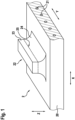
- Fig.1 shows a schematic perspective view of a crawler track 2 according to the invention in accordance with a first exemplary embodiment.
- the crawler track 2 is designed as a rubber crawler track 2 and has a chain body 20 which is made of an elastomeric material in which a plurality of tension members 21 in the form of steel cables 21 are embedded.
- the chain body 20 and the tension members 21 are endlessly closed in the circumferential direction or in the direction of rotation X.
- the chain body 20 On the surface of its upper side, the chain body 20 has a plurality of outer profiling elements 22, of which in the Fig. 1 to 5 in each case an outer profiling element 22 is shown as an example.
- the outer profiling element 22 can also be referred to as a stud 22, which can be functionally divided into an upwardly pointing stud body 23 and a stud foot 24, which connects the stud body 22 to the chain body 20.
- the surface on which the cleat body 23 and the cleat foot 24 meet can be regarded as the boundary 25 between the cleat body 23 and the cleat foot 24, which simultaneously represents the wear limit 25, upon reaching which the cleat body 23 can be regarded as being worn to such an extent that the rubber crawler track 2 should no longer be used.
- the material of the stud body 23 has a different color than the material of the stud foot 24.
- the stud body 22 can be visually distinguished from the stud foot 24 in a simple and reliable manner, so that wear on the stud body 23 can also be visually recognized in a simple and reliable manner. From this, conclusions can be drawn about the extent of the abrasion or wear on the stud body 23.
- the stud body 23 according to the first embodiment could also be covered with a different colored layer in order to at least partially have the properties described above. This can simplify the implementation of the present invention according to the first embodiment.
- the implementation of the first embodiment as a different colored material can be safer because the color of the material can completely penetrate the stud body 23 and can thus be more securely connected to the stud body 23 and also be visible from above than a layer applied to the sides or flanks of the stud body 23.
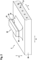
- Fig.2 shows a schematic perspective view of a crawler track 2 according to the invention according to a second embodiment.
- a colored material is arranged as a marking 26 between the cleat body 23 and the cleat foot 24 in order to mark the wear limit 25, which can lie within the colored marking 26 or between the colored marking 26 and the cleat body 23.
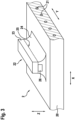
- Fig.3 shows a schematic perspective view of a crawler track 2 according to the invention in accordance with a third exemplary embodiment.
- a colored material is introduced as a marking 26 below the stud body 23 in the stud foot 24.
- a colored material in the form of a separate body can be used, which is introduced at this point into a corresponding recess in the stud foot 24 before vulcanization and is vulcanized together with the stud body 23 and the stud foot 24.
- Such a separate body as an elastomer colored material can be referred to as a vulcanette.
- a colored marking 26 can be easily implemented.
- the flanks of the stud 22 at the height Z or in the longitudinal direction X can remain free of a marking 26, since here the marking 26 could quickly disappear due to the wear of the ground without this being able to indicate that the wear limit 25 has been reached.
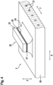
- Fig.4 shows a schematic perspective view of a crawler track 2 according to the invention according to a fourth embodiment.
- the wear limit 25 is marked by a circumferential depression 27 in the form of a groove 27, so that the wear limit 25 can be recognized both visually and particularly haptically.
- Fig.5 shows a schematic perspective view of a crawler track 2 according to the invention according to a fifth embodiment.
- the wear limit 25 is marked by a circumferential highlight 27 in the form of an edge 27, so that the wear limit 25 can be recognized both visually and particularly haptically.
- the stud body 23 and the stud foot 24 are made of two different elastomer materials, which are designed for the respective requirements.
- the stud body 23 is made of a material which is more abrasion-resistant than the material of the stud foot 24. If the wear limit 25 is thus reached, it can be recognized according to the invention that the stud body 23, as the more abrasion-resistant part of the stud 22, has been worn down and the stud foot 24, as the less abrasion-resistant part of the stud 22, can now come into abrasive contact with the ground. Therefore, when the wear limit 25 is reached, the rubber crawler track 2 should no longer be used and should be replaced.
Landscapes
- Engineering & Computer Science (AREA)
- Chemical & Material Sciences (AREA)
- Combustion & Propulsion (AREA)
- Transportation (AREA)
- Mechanical Engineering (AREA)
- Tires In General (AREA)
- Golf Clubs (AREA)
Claims (8)
- Chenille (2), en particulier chenille en caoutchouc (2), comprenantun corps de chenille (20), et comprenantau moins un élément de profilage extérieur (22), de manière préférée comprenant une pluralité d'éléments de profilage extérieurs (22) orientés vers l'extérieur à partir du corps de chenille (20),dans laquelle l'élément de profilage extérieur (22) présente un corps de crampon (23) orienté vers l'extérieur et un pied de crampon (24) reliant le corps de crampon (23) au corps de chenille (20), etdans laquelle l'élément de profilage extérieur (22) présente au moins par sections un marquage (26, 27, 28) pouvant rendre optiquement identifiable la limite (25) entre le corps de crampon (23) et le pied de crampon (24), caractérisée en ce quele corps de crampon (23) présente un matériau d'une première couleur et le pied de crampon (24) présente un matériau d'une seconde couleur, les deux couleurs étant différentes l'une de l'autre.
- Chenille (2), en particulier chenille en caoutchouc (2), comprenantun corps de chenille (20), et comprenantau moins un élément de profilage extérieur (22), de manière préférée comprenant une pluralité d'éléments de profilage extérieurs (22) orientés vers l'extérieur à partir du corps de chenille (20),dans laquelle l'élément de profilage extérieur (22) présente un corps de crampon (23) orienté vers l'extérieur et un pied de crampon (24) reliant le corps de crampon (23) au corps de chenille (20), etdans laquelle l'élément de profilage extérieur (22) présente au moins par sections un marquage (26, 27, 28) pouvant rendre optiquement identifiable la limite (25) entre le corps de crampon (23) et le pied de crampon (24), caractérisée en ce queun matériau coloré faisant office de marquage (26) et dont la couleur se différencie de celle(s) du matériau du corps de crampon (23) et du matériau du pied de crampon (24) est agencé au moins par sections entre le corps de crampon (23) et le pied de crampon (24).
- Chenille (2), en particulier chenille en caoutchouc (2), comprenantun corps de chenille (20), et comprenantau moins un élément de profilage extérieur (22), de manière préférée comprenant une pluralité d'éléments de profilage extérieurs (22) orientés vers l'extérieur à partir du corps de chenille (20),dans laquelle l'élément de profilage extérieur (22) présente un corps de crampon (23) orienté vers l'extérieur et un pied de crampon (24) reliant le corps de crampon (23) au corps de chenille (20), etdans laquelle l'élément de profilage extérieur (22) présente au moins par sections un marquage (26, 27, 28) pouvant rendre optiquement identifiable la limite (25) entre le corps de crampon (23) et le pied de crampon (24), caractérisée en ce quel'élément de profilage extérieur (22) présente, au moins par sections là où la limite (25) s'étend entre le corps de crampon (23) et le pied de crampon (24), un marquage coloré (26), et un marquage coloré (26) dont la couleur se différencie de celle(s) du matériau du corps de crampon (23) et du matériau du pied de crampon (24) y est en particulier appliqué depuis l'extérieur.
- Chenille (2) selon l'une quelconque des revendications précédentes, caractérisée en ce que
le corps de crampon (23) et le pied de crampon (24) présentent des matériaux différents, de manière préférée sont constitués de matériaux différents. - Chenille (2) selon la revendication 4, caractérisée en ce que
le corps de crampon (23) présente un matériau, de manière préférée est constitué d'un matériau, qui est davantage résistant à l'abrasion et/ou qui peut fournir par rapport au terrain sous-jacent une meilleure adhérence et/ou un meilleur amortissement que le matériau du pied de crampon (24). - Chenille (2) selon la revendication 4 ou 5, caractérisée en ce que le pied de crampon (24) présente un matériau, de manière préférée est constitué d'un matériau, qui présente un échauffement intrinsèque plus faible et/ou une résistance dynamique plus élevée et/ou une meilleure liaison au matériau du corps de chenille (20) que le matériau du corps de crampon (23).
- Chenille (2) selon l'une quelconque des revendications précédentes, caractérisée en ce que
le matériau du corps de crampon (23) et/ou le matériau du pied de crampon (24) présente(nt) un matériau élastomère, de manière préférée est/sont constitué(s) d'un matériau élastomère. - Chenille (2) selon l'une quelconque des revendications précédentes, caractérisée en ce que
une pluralité de pièces de traction (21), de manière préférée des câbles en acier (21), sont intégrées dans le corps de chenille (20).
Applications Claiming Priority (2)
| Application Number | Priority Date | Filing Date | Title |
|---|---|---|---|
| DE102016225423.5A DE102016225423A1 (de) | 2016-12-19 | 2016-12-19 | Raupenkette, insbesondere Gummiraupenkette |
| PCT/EP2017/076654 WO2018114085A1 (fr) | 2016-12-19 | 2017-10-19 | Chenille, en particulier chenille en caoutchouc |
Publications (2)
| Publication Number | Publication Date |
|---|---|
| EP3554929A1 EP3554929A1 (fr) | 2019-10-23 |
| EP3554929B1 true EP3554929B1 (fr) | 2024-05-22 |
Family
ID=60138378
Family Applications (1)
| Application Number | Title | Priority Date | Filing Date |
|---|---|---|---|
| EP17786907.0A Active EP3554929B1 (fr) | 2016-12-19 | 2017-10-19 | Chenille, en particulier chenille en caoutchouc |
Country Status (5)
| Country | Link |
|---|---|
| US (1) | US11370499B2 (fr) |
| EP (1) | EP3554929B1 (fr) |
| DE (1) | DE102016225423A1 (fr) |
| PL (1) | PL3554929T3 (fr) |
| WO (1) | WO2018114085A1 (fr) |
Families Citing this family (1)
| Publication number | Priority date | Publication date | Assignee | Title |
|---|---|---|---|---|
| US12116058B2 (en) | 2021-10-04 | 2024-10-15 | Caterpillar Inc. | Track shoe assembly including a shoe plate and a grouser and related method of manufacture |
Family Cites Families (16)
| Publication number | Priority date | Publication date | Assignee | Title |
|---|---|---|---|---|
| US2874005A (en) * | 1954-10-01 | 1959-02-17 | Bofors Ab | Reinforcement means for a track plate of a track laying vehicle |
| CA2182845C (fr) * | 1996-08-07 | 1999-03-30 | Denis Courtemanche | Chenille de transmission de motoneige a sculptures attenuatrices de bruit |
| JPH11301535A (ja) * | 1998-04-24 | 1999-11-02 | Bridgestone Corp | ゴムクロ−ラ構造 |
| US6086811A (en) | 1998-04-29 | 2000-07-11 | The Goodyear Tire & Rubber Company | Molding system for rubber tractor tracks |
| US6177042B1 (en) | 1998-11-23 | 2001-01-23 | The Goodyear Tire & Rubber Company | Method and apparatus for making integral rubber tractor tracks |
| JP2001180544A (ja) * | 1999-12-24 | 2001-07-03 | Komatsu Ltd | 弾性体履板 |
| CA2390209A1 (fr) * | 2001-08-10 | 2003-02-10 | The Goodyear Tire & Rubber Company | Chenille continue en caoutchouc constituee d'une semelle a base de polyurethane et d'une carcasse en caoutchouc, et vehicule pourvu d'une telle chenille |
| CA2436493A1 (fr) | 2002-08-08 | 2004-02-08 | Bombardier Inc. | Chenille de vehicule permettant une orientation amelioree |
| CA2505307A1 (fr) * | 2005-04-26 | 2006-10-26 | Camoplast Inc. | Piste a tenons de traction a tranches multiples |
| WO2008106230A1 (fr) * | 2007-02-28 | 2008-09-04 | Mclaren Group Holdings Pte. Ltd. | Route décalée |
| ITMI20071248A1 (it) * | 2007-06-21 | 2008-12-22 | Rolic Invest Sarl | Rampone per cingoli di veicoli cingolati, in particolare veicoli battipista |
| US8567876B2 (en) | 2009-11-25 | 2013-10-29 | Veyance Technologies, Inc. | Vehicle track |
| US9067631B1 (en) | 2010-12-14 | 2015-06-30 | Camoplast Solideal Inc. | Endless track for traction of a vehicle |
| EP2502807B1 (fr) * | 2011-03-21 | 2018-07-11 | ContiTech USA, Inc. | Chenille de véhicule |
| DE102015205071A1 (de) | 2015-03-20 | 2016-09-22 | Contitech Transportbandsysteme Gmbh | Vorrichtung und Verfahren zur Herstellung einer Gummiraupenkette mit Zugträgern |
| KR101670680B1 (ko) * | 2016-05-03 | 2016-10-31 | 티알벨트랙 주식회사 | 마모한계 시점을 표시하는 크로라 |
-
2016
- 2016-12-19 DE DE102016225423.5A patent/DE102016225423A1/de not_active Withdrawn
-
2017
- 2017-10-19 PL PL17786907.0T patent/PL3554929T3/pl unknown
- 2017-10-19 US US16/471,379 patent/US11370499B2/en active Active
- 2017-10-19 EP EP17786907.0A patent/EP3554929B1/fr active Active
- 2017-10-19 WO PCT/EP2017/076654 patent/WO2018114085A1/fr not_active Ceased
Also Published As
| Publication number | Publication date |
|---|---|
| PL3554929T3 (pl) | 2024-10-14 |
| EP3554929A1 (fr) | 2019-10-23 |
| US11370499B2 (en) | 2022-06-28 |
| DE102016225423A1 (de) | 2018-06-21 |
| WO2018114085A1 (fr) | 2018-06-28 |
| US20190315418A1 (en) | 2019-10-17 |
Similar Documents
| Publication | Publication Date | Title |
|---|---|---|
| DE69028387T2 (de) | Lauffläche für Luftreifen | |
| DE2228219C3 (de) | Fahrzeugluftreifen für Erdbewegungsmaschinen mit Radialkarkasse und Verstärkungseinlage | |
| DE3879416T2 (de) | Radialer reifen. | |
| DE602004009186T2 (de) | Laufflächeprofil das mindestens ein eingesetztes element hat | |
| DE2841132A1 (de) | Luftreifen fuer kraftfahrzeuge | |
| DE60131480T2 (de) | Geländeluftreifen | |
| DE1480981A1 (de) | Fahrzeugluftreifen | |
| EP3271164B1 (fr) | Dispositif et procédé servant à fabriquer une chenille en caoutchouc pourvue d'armatures de renforcement en traction | |
| WO2013064300A1 (fr) | Pneumatique de véhicule | |
| EP3554929B1 (fr) | Chenille, en particulier chenille en caoutchouc | |
| DE112012002467T5 (de) | Luftreifen und Verfahren zum Herstellen eines Luftreifens | |
| DE3335899A1 (de) | Vollreifen aus gummi oder einem analogen material, mit abnehmbarem laufband | |
| EP3707014B1 (fr) | Crampon destiné à être ancré dans un trou de crampon d'une bande de roulement d'un pneumatique de véhicule | |
| EP2943359A1 (fr) | Pneu de véhicule pour une utilisation en conditions de conduite hivernales | |
| EP3642053B1 (fr) | Pneumatique avec bandage de roulement muni des crampons | |
| DE2109876C3 (de) | Reifen für Schwerfahrzeuge mit einer Reifenschutzkette | |
| WO2018114084A1 (fr) | Chenille, en particulier chenille en caoutchouc | |
| DE29506363U1 (de) | Verbessertes Raupenglied, insbesondere zur Anwendung in Raupenmaschinen geringer Leistungsfähigkeit | |
| DE2305199A1 (de) | Reifen | |
| DE69509298T2 (de) | Fahrzeugluftreifen | |
| WO2017016677A1 (fr) | Insert de marche d'urgence | |
| EP3538384B1 (fr) | Pneumatique de véhicule | |
| DE69007019T2 (de) | Lauffläche für LKW-Gürtelreifen. | |
| EP3392065B1 (fr) | Pneu de véhicule | |
| DE3435872C2 (fr) |
Legal Events
| Date | Code | Title | Description |
|---|---|---|---|
| STAA | Information on the status of an ep patent application or granted ep patent |
Free format text: STATUS: UNKNOWN |
|
| STAA | Information on the status of an ep patent application or granted ep patent |
Free format text: STATUS: THE INTERNATIONAL PUBLICATION HAS BEEN MADE |
|
| PUAI | Public reference made under article 153(3) epc to a published international application that has entered the european phase |
Free format text: ORIGINAL CODE: 0009012 |
|
| STAA | Information on the status of an ep patent application or granted ep patent |
Free format text: STATUS: REQUEST FOR EXAMINATION WAS MADE |
|
| 17P | Request for examination filed |
Effective date: 20190719 |
|
| AK | Designated contracting states |
Kind code of ref document: A1 Designated state(s): AL AT BE BG CH CY CZ DE DK EE ES FI FR GB GR HR HU IE IS IT LI LT LU LV MC MK MT NL NO PL PT RO RS SE SI SK SM TR |
|
| AX | Request for extension of the european patent |
Extension state: BA ME |
|
| DAV | Request for validation of the european patent (deleted) | ||
| DAX | Request for extension of the european patent (deleted) | ||
| RAP1 | Party data changed (applicant data changed or rights of an application transferred) |
Owner name: CONTITECH TRANSPORTBANDSYSTEME GMBH |
|
| STAA | Information on the status of an ep patent application or granted ep patent |
Free format text: STATUS: EXAMINATION IS IN PROGRESS |
|
| 17Q | First examination report despatched |
Effective date: 20210309 |
|
| RAP1 | Party data changed (applicant data changed or rights of an application transferred) |
Owner name: LOC PERFORMANCE PRODUCTS, LLC |
|
| RAP1 | Party data changed (applicant data changed or rights of an application transferred) |
Owner name: LOC PERFORMANCE PRODUCTS, LLC |
|
| GRAP | Despatch of communication of intention to grant a patent |
Free format text: ORIGINAL CODE: EPIDOSNIGR1 |
|
| STAA | Information on the status of an ep patent application or granted ep patent |
Free format text: STATUS: GRANT OF PATENT IS INTENDED |
|
| INTG | Intention to grant announced |
Effective date: 20240102 |
|
| GRAS | Grant fee paid |
Free format text: ORIGINAL CODE: EPIDOSNIGR3 |
|
| GRAA | (expected) grant |
Free format text: ORIGINAL CODE: 0009210 |
|
| STAA | Information on the status of an ep patent application or granted ep patent |
Free format text: STATUS: THE PATENT HAS BEEN GRANTED |
|
| AK | Designated contracting states |
Kind code of ref document: B1 Designated state(s): AL AT BE BG CH CY CZ DE DK EE ES FI FR GB GR HR HU IE IS IT LI LT LU LV MC MK MT NL NO PL PT RO RS SE SI SK SM TR |
|
| P01 | Opt-out of the competence of the unified patent court (upc) registered |
Effective date: 20240411 |
|
| REG | Reference to a national code |
Ref country code: GB Ref legal event code: FG4D Free format text: NOT ENGLISH |
|
| REG | Reference to a national code |
Ref country code: CH Ref legal event code: EP |
|
| REG | Reference to a national code |
Ref country code: DE Ref legal event code: R096 Ref document number: 502017016136 Country of ref document: DE |
|
| REG | Reference to a national code |
Ref country code: IE Ref legal event code: FG4D Free format text: LANGUAGE OF EP DOCUMENT: GERMAN |
|
| REG | Reference to a national code |
Ref country code: RO Ref legal event code: EPE |
|
| REG | Reference to a national code |
Ref country code: LT Ref legal event code: MG9D |
|
| REG | Reference to a national code |
Ref country code: NL Ref legal event code: MP Effective date: 20240522 |
|
| PG25 | Lapsed in a contracting state [announced via postgrant information from national office to epo] |
Ref country code: IS Free format text: LAPSE BECAUSE OF FAILURE TO SUBMIT A TRANSLATION OF THE DESCRIPTION OR TO PAY THE FEE WITHIN THE PRESCRIBED TIME-LIMIT Effective date: 20240922 |
|
| PG25 | Lapsed in a contracting state [announced via postgrant information from national office to epo] |
Ref country code: BG Free format text: LAPSE BECAUSE OF FAILURE TO SUBMIT A TRANSLATION OF THE DESCRIPTION OR TO PAY THE FEE WITHIN THE PRESCRIBED TIME-LIMIT Effective date: 20240522 |
|
| PG25 | Lapsed in a contracting state [announced via postgrant information from national office to epo] |
Ref country code: HR Free format text: LAPSE BECAUSE OF FAILURE TO SUBMIT A TRANSLATION OF THE DESCRIPTION OR TO PAY THE FEE WITHIN THE PRESCRIBED TIME-LIMIT Effective date: 20240522 Ref country code: FI Free format text: LAPSE BECAUSE OF FAILURE TO SUBMIT A TRANSLATION OF THE DESCRIPTION OR TO PAY THE FEE WITHIN THE PRESCRIBED TIME-LIMIT Effective date: 20240522 |
|
| PG25 | Lapsed in a contracting state [announced via postgrant information from national office to epo] |
Ref country code: GR Free format text: LAPSE BECAUSE OF FAILURE TO SUBMIT A TRANSLATION OF THE DESCRIPTION OR TO PAY THE FEE WITHIN THE PRESCRIBED TIME-LIMIT Effective date: 20240823 |
|
| PG25 | Lapsed in a contracting state [announced via postgrant information from national office to epo] |
Ref country code: PT Free format text: LAPSE BECAUSE OF FAILURE TO SUBMIT A TRANSLATION OF THE DESCRIPTION OR TO PAY THE FEE WITHIN THE PRESCRIBED TIME-LIMIT Effective date: 20240923 |
|
| PG25 | Lapsed in a contracting state [announced via postgrant information from national office to epo] |
Ref country code: NL Free format text: LAPSE BECAUSE OF FAILURE TO SUBMIT A TRANSLATION OF THE DESCRIPTION OR TO PAY THE FEE WITHIN THE PRESCRIBED TIME-LIMIT Effective date: 20240522 |
|
| PG25 | Lapsed in a contracting state [announced via postgrant information from national office to epo] |
Ref country code: ES Free format text: LAPSE BECAUSE OF FAILURE TO SUBMIT A TRANSLATION OF THE DESCRIPTION OR TO PAY THE FEE WITHIN THE PRESCRIBED TIME-LIMIT Effective date: 20240522 |
|
| PG25 | Lapsed in a contracting state [announced via postgrant information from national office to epo] |
Ref country code: LV Free format text: LAPSE BECAUSE OF FAILURE TO SUBMIT A TRANSLATION OF THE DESCRIPTION OR TO PAY THE FEE WITHIN THE PRESCRIBED TIME-LIMIT Effective date: 20240522 |
|
| PG25 | Lapsed in a contracting state [announced via postgrant information from national office to epo] |
Ref country code: PT Free format text: LAPSE BECAUSE OF FAILURE TO SUBMIT A TRANSLATION OF THE DESCRIPTION OR TO PAY THE FEE WITHIN THE PRESCRIBED TIME-LIMIT Effective date: 20240923 Ref country code: NO Free format text: LAPSE BECAUSE OF FAILURE TO SUBMIT A TRANSLATION OF THE DESCRIPTION OR TO PAY THE FEE WITHIN THE PRESCRIBED TIME-LIMIT Effective date: 20240822 Ref country code: NL Free format text: LAPSE BECAUSE OF FAILURE TO SUBMIT A TRANSLATION OF THE DESCRIPTION OR TO PAY THE FEE WITHIN THE PRESCRIBED TIME-LIMIT Effective date: 20240522 Ref country code: LV Free format text: LAPSE BECAUSE OF FAILURE TO SUBMIT A TRANSLATION OF THE DESCRIPTION OR TO PAY THE FEE WITHIN THE PRESCRIBED TIME-LIMIT Effective date: 20240522 Ref country code: IS Free format text: LAPSE BECAUSE OF FAILURE TO SUBMIT A TRANSLATION OF THE DESCRIPTION OR TO PAY THE FEE WITHIN THE PRESCRIBED TIME-LIMIT Effective date: 20240922 Ref country code: HR Free format text: LAPSE BECAUSE OF FAILURE TO SUBMIT A TRANSLATION OF THE DESCRIPTION OR TO PAY THE FEE WITHIN THE PRESCRIBED TIME-LIMIT Effective date: 20240522 Ref country code: GR Free format text: LAPSE BECAUSE OF FAILURE TO SUBMIT A TRANSLATION OF THE DESCRIPTION OR TO PAY THE FEE WITHIN THE PRESCRIBED TIME-LIMIT Effective date: 20240823 Ref country code: FI Free format text: LAPSE BECAUSE OF FAILURE TO SUBMIT A TRANSLATION OF THE DESCRIPTION OR TO PAY THE FEE WITHIN THE PRESCRIBED TIME-LIMIT Effective date: 20240522 Ref country code: ES Free format text: LAPSE BECAUSE OF FAILURE TO SUBMIT A TRANSLATION OF THE DESCRIPTION OR TO PAY THE FEE WITHIN THE PRESCRIBED TIME-LIMIT Effective date: 20240522 Ref country code: BG Free format text: LAPSE BECAUSE OF FAILURE TO SUBMIT A TRANSLATION OF THE DESCRIPTION OR TO PAY THE FEE WITHIN THE PRESCRIBED TIME-LIMIT Effective date: 20240522 Ref country code: RS Free format text: LAPSE BECAUSE OF FAILURE TO SUBMIT A TRANSLATION OF THE DESCRIPTION OR TO PAY THE FEE WITHIN THE PRESCRIBED TIME-LIMIT Effective date: 20240822 |
|
| PG25 | Lapsed in a contracting state [announced via postgrant information from national office to epo] |
Ref country code: DK Free format text: LAPSE BECAUSE OF FAILURE TO SUBMIT A TRANSLATION OF THE DESCRIPTION OR TO PAY THE FEE WITHIN THE PRESCRIBED TIME-LIMIT Effective date: 20240522 |
|
| PG25 | Lapsed in a contracting state [announced via postgrant information from national office to epo] |
Ref country code: EE Free format text: LAPSE BECAUSE OF FAILURE TO SUBMIT A TRANSLATION OF THE DESCRIPTION OR TO PAY THE FEE WITHIN THE PRESCRIBED TIME-LIMIT Effective date: 20240522 |
|
| PG25 | Lapsed in a contracting state [announced via postgrant information from national office to epo] |
Ref country code: CZ Free format text: LAPSE BECAUSE OF FAILURE TO SUBMIT A TRANSLATION OF THE DESCRIPTION OR TO PAY THE FEE WITHIN THE PRESCRIBED TIME-LIMIT Effective date: 20240522 |
|
| PG25 | Lapsed in a contracting state [announced via postgrant information from national office to epo] |
Ref country code: SK Free format text: LAPSE BECAUSE OF FAILURE TO SUBMIT A TRANSLATION OF THE DESCRIPTION OR TO PAY THE FEE WITHIN THE PRESCRIBED TIME-LIMIT Effective date: 20240522 |
|
| PG25 | Lapsed in a contracting state [announced via postgrant information from national office to epo] |
Ref country code: SM Free format text: LAPSE BECAUSE OF FAILURE TO SUBMIT A TRANSLATION OF THE DESCRIPTION OR TO PAY THE FEE WITHIN THE PRESCRIBED TIME-LIMIT Effective date: 20240522 |
|
| PG25 | Lapsed in a contracting state [announced via postgrant information from national office to epo] |
Ref country code: SM Free format text: LAPSE BECAUSE OF FAILURE TO SUBMIT A TRANSLATION OF THE DESCRIPTION OR TO PAY THE FEE WITHIN THE PRESCRIBED TIME-LIMIT Effective date: 20240522 Ref country code: SK Free format text: LAPSE BECAUSE OF FAILURE TO SUBMIT A TRANSLATION OF THE DESCRIPTION OR TO PAY THE FEE WITHIN THE PRESCRIBED TIME-LIMIT Effective date: 20240522 Ref country code: EE Free format text: LAPSE BECAUSE OF FAILURE TO SUBMIT A TRANSLATION OF THE DESCRIPTION OR TO PAY THE FEE WITHIN THE PRESCRIBED TIME-LIMIT Effective date: 20240522 Ref country code: DK Free format text: LAPSE BECAUSE OF FAILURE TO SUBMIT A TRANSLATION OF THE DESCRIPTION OR TO PAY THE FEE WITHIN THE PRESCRIBED TIME-LIMIT Effective date: 20240522 Ref country code: CZ Free format text: LAPSE BECAUSE OF FAILURE TO SUBMIT A TRANSLATION OF THE DESCRIPTION OR TO PAY THE FEE WITHIN THE PRESCRIBED TIME-LIMIT Effective date: 20240522 |
|
| REG | Reference to a national code |
Ref country code: DE Ref legal event code: R097 Ref document number: 502017016136 Country of ref document: DE |
|
| PLBE | No opposition filed within time limit |
Free format text: ORIGINAL CODE: 0009261 |
|
| STAA | Information on the status of an ep patent application or granted ep patent |
Free format text: STATUS: NO OPPOSITION FILED WITHIN TIME LIMIT |
|
| PG25 | Lapsed in a contracting state [announced via postgrant information from national office to epo] |
Ref country code: SI Free format text: LAPSE BECAUSE OF FAILURE TO SUBMIT A TRANSLATION OF THE DESCRIPTION OR TO PAY THE FEE WITHIN THE PRESCRIBED TIME-LIMIT Effective date: 20240522 |
|
| 26N | No opposition filed |
Effective date: 20250225 |
|
| REG | Reference to a national code |
Ref country code: CH Ref legal event code: PL |
|
| PG25 | Lapsed in a contracting state [announced via postgrant information from national office to epo] |
Ref country code: MC Free format text: LAPSE BECAUSE OF FAILURE TO SUBMIT A TRANSLATION OF THE DESCRIPTION OR TO PAY THE FEE WITHIN THE PRESCRIBED TIME-LIMIT Effective date: 20240522 |
|
| PG25 | Lapsed in a contracting state [announced via postgrant information from national office to epo] |
Ref country code: BE Free format text: LAPSE BECAUSE OF NON-PAYMENT OF DUE FEES Effective date: 20241031 Ref country code: LU Free format text: LAPSE BECAUSE OF NON-PAYMENT OF DUE FEES Effective date: 20241019 |
|
| PG25 | Lapsed in a contracting state [announced via postgrant information from national office to epo] |
Ref country code: CH Free format text: LAPSE BECAUSE OF NON-PAYMENT OF DUE FEES Effective date: 20241031 |
|
| REG | Reference to a national code |
Ref country code: BE Ref legal event code: MM Effective date: 20241031 |
|
| PG25 | Lapsed in a contracting state [announced via postgrant information from national office to epo] |
Ref country code: SE Free format text: LAPSE BECAUSE OF FAILURE TO SUBMIT A TRANSLATION OF THE DESCRIPTION OR TO PAY THE FEE WITHIN THE PRESCRIBED TIME-LIMIT Effective date: 20240522 |
|
| PG25 | Lapsed in a contracting state [announced via postgrant information from national office to epo] |
Ref country code: IE Free format text: LAPSE BECAUSE OF NON-PAYMENT OF DUE FEES Effective date: 20241019 |
|
| REG | Reference to a national code |
Ref country code: AT Ref legal event code: MM01 Ref document number: 1688566 Country of ref document: AT Kind code of ref document: T Effective date: 20241019 |
|
| PGFP | Annual fee paid to national office [announced via postgrant information from national office to epo] |
Ref country code: DE Payment date: 20251029 Year of fee payment: 9 |
|
| PGFP | Annual fee paid to national office [announced via postgrant information from national office to epo] |
Ref country code: GB Payment date: 20251024 Year of fee payment: 9 |
|
| PG25 | Lapsed in a contracting state [announced via postgrant information from national office to epo] |
Ref country code: AT Free format text: LAPSE BECAUSE OF NON-PAYMENT OF DUE FEES Effective date: 20241019 |
|
| PGFP | Annual fee paid to national office [announced via postgrant information from national office to epo] |
Ref country code: IT Payment date: 20251030 Year of fee payment: 9 |
|
| PGFP | Annual fee paid to national office [announced via postgrant information from national office to epo] |
Ref country code: FR Payment date: 20251024 Year of fee payment: 9 |
|
| PGFP | Annual fee paid to national office [announced via postgrant information from national office to epo] |
Ref country code: TR Payment date: 20251013 Year of fee payment: 9 |
|
| PGFP | Annual fee paid to national office [announced via postgrant information from national office to epo] |
Ref country code: PL Payment date: 20251002 Year of fee payment: 9 |
|
| PGFP | Annual fee paid to national office [announced via postgrant information from national office to epo] |
Ref country code: RO Payment date: 20251014 Year of fee payment: 9 |
|
| PG25 | Lapsed in a contracting state [announced via postgrant information from national office to epo] |
Ref country code: CY Free format text: LAPSE BECAUSE OF FAILURE TO SUBMIT A TRANSLATION OF THE DESCRIPTION OR TO PAY THE FEE WITHIN THE PRESCRIBED TIME-LIMIT; INVALID AB INITIO Effective date: 20171019 |
|
| PG25 | Lapsed in a contracting state [announced via postgrant information from national office to epo] |
Ref country code: HU Free format text: LAPSE BECAUSE OF FAILURE TO SUBMIT A TRANSLATION OF THE DESCRIPTION OR TO PAY THE FEE WITHIN THE PRESCRIBED TIME-LIMIT; INVALID AB INITIO Effective date: 20171019 |