EP3554763B1 - Dispositif d'enfoncement et bandes d'éléments de fixation - Google Patents
Dispositif d'enfoncement et bandes d'éléments de fixation Download PDFInfo
- Publication number
- EP3554763B1 EP3554763B1 EP17807889.5A EP17807889A EP3554763B1 EP 3554763 B1 EP3554763 B1 EP 3554763B1 EP 17807889 A EP17807889 A EP 17807889A EP 3554763 B1 EP3554763 B1 EP 3554763B1
- Authority
- EP
- European Patent Office
- Prior art keywords
- fastening
- transport direction
- fastening elements
- magazine
- receptacles
- Prior art date
- Legal status (The legal status is an assumption and is not a legal conclusion. Google has not performed a legal analysis and makes no representation as to the accuracy of the status listed.)
- Active
Links
Images


Classifications
-
- B—PERFORMING OPERATIONS; TRANSPORTING
- B25—HAND TOOLS; PORTABLE POWER-DRIVEN TOOLS; MANIPULATORS
- B25C—HAND-HELD NAILING OR STAPLING TOOLS; MANUALLY OPERATED PORTABLE STAPLING TOOLS
- B25C1/00—Hand-held nailing tools; Nail feeding devices
- B25C1/001—Nail feeding devices
- B25C1/005—Nail feeding devices for rows of contiguous nails
-
- F—MECHANICAL ENGINEERING; LIGHTING; HEATING; WEAPONS; BLASTING
- F16—ENGINEERING ELEMENTS AND UNITS; GENERAL MEASURES FOR PRODUCING AND MAINTAINING EFFECTIVE FUNCTIONING OF MACHINES OR INSTALLATIONS; THERMAL INSULATION IN GENERAL
- F16B—DEVICES FOR FASTENING OR SECURING CONSTRUCTIONAL ELEMENTS OR MACHINE PARTS TOGETHER, e.g. NAILS, BOLTS, CIRCLIPS, CLAMPS, CLIPS OR WEDGES; JOINTS OR JOINTING
- F16B15/00—Nails; Staples
- F16B15/08—Nails; Staples formed in integral series but easily separable
Definitions
- the application relates to a device for driving fasteners into a substrate and a fastener strip.
- Driving devices usually have a piston that can be moved in a setting channel to transmit energy to the fastening element.
- the energy required for this must be made available in a very short time, which is why, for example, with so-called spring nailers, a spring is first tensioned, which suddenly releases the tension energy to the piston during the driving process and accelerates it towards the fastening element.
- driving devices usually have a magazine for transporting the fastening elements to the setting channel.
- the fasteners are usually provided in the form of strips, such strip comprising receptacles for the fasteners arranged in a row.
- the recordings of a strip are connected to each other using connecting bars.
- a nail gun is known that has a magazine in which pins are transported in two rows next to each other. The pins are driven into a substrate in pairs, each forming a nail.
- a nail magazine unit which includes a holding element for inclusion in a magazine of a nail driving device.
- the holding element is plate-shaped with two or more grooves open on one side of the plate for receiving two or more rows of individual nails next to each other.
- a nail strip which has a back section and an upper and a lower joint section.
- the joint sections are each bent around a pivot line so that they are arranged at right angles with respect to the back section.
- Nails are each held together by a recess in the upper joint section and a recess in the lower joint section and are arranged in a row along the nail strip.
- a method for driving fastening elements into a substrate is provided by means of a device, the device having a setting channel, an energy transmission element movable in the setting channel in a fastening direction for transmitting energy to one of the fastening elements, and a magazine for transporting the fastening elements in a transport direction to the setting channel.
- the magazine simultaneously transports several rows of fasteners, which are arranged one behind the other in a transverse direction oriented perpendicular to the transport direction and perpendicular to the fastening direction, in order to transport fasteners from different rows of the several rows of fasteners alternately into the setting channel.
- the device has an insertion bevel inclined to the transport direction for guiding the frontmost fastening element of the several rows of fastening elements in the transport direction into the setting channel, the insertion bevel aligning the row of the frontmost fastening element of the several rows of fastening elements with the setting channel.
- the insertion bevel is preferably rigidly connected to the setting channel.
- the energy transmission element preferably has a contact end pointing in the fastening direction for contacting a fastening element arranged in the setting channel.
- the contact end comprises a flat contact surface oriented perpendicular to the fastening direction, the energy transmission element preferably being designed as a striking or thrust piston for driving in nails, bolts or the like.
- the contact end comprises a screw drive, wherein the energy transmission element is preferably designed as a rotationally driven screw bit for driving screws or the like.
- the magazine has a feed element which applies a force in the transport direction to the several rows of fastening elements.
- the feed element has a plurality of contact surfaces that are offset from one another in the transport direction for contact with one of the several rows of fastening elements.
- this has Feed element only has one contact surface for contact with exactly one of the several rows of fastening elements.
- An advantageous embodiment is characterized in that the device has a pressing element which is offset relative to the magazine when the device is pressed against the surface, and which has a force transmission surface which exerts a force on the frontmost fastening element of the several rows of fastening elements in the transport direction transferred to the setting channel in order to position the frontmost fastening element in the setting channel.
- the pressing element preferably comprises a control surface for guiding the frontmost fastening element of the several rows of fastening elements in the transport direction into the setting channel.
- the magazine has a guide channel for guiding the multiple rows of fastening elements, the guide channel opening into the setting channel with a mouth, the mouth moving back and forth in the transverse direction between a first position and a second position becomes.
- the guide channel preferably has a counter-control surface which controls the mouth into the first or second position when the control surface of the pressing element engages the counter-control surface.
- the guide channel is also preferably pivoted about a pivot axis offset from the setting channel.
- the pivot axis is particularly preferably aligned parallel to the fastening direction. Also particularly preferably, the pivot axis cuts the guide channel or an imaginary extension of the guide channel in or against the transport direction.
- a fastener strip is intended for use in a device for driving fasteners into a substrate and comprises a plurality of rows of receptacles for fasteners aligned in a transport direction as well as fasteners received in the receptacles and defining a fastening direction, the rows of receptacles are arranged one behind the other in a transverse direction oriented perpendicular to the transport direction and perpendicular to the fastening direction. Furthermore, the fastener strip comprises a connecting web which connects a receptacle of a first row of the plurality of rows to a receptacle of a second row of the plurality of rows.
- Each recording is related to all other recordings of the several Rows of recordings offset in the transport direction.
- the offset measured in the transport direction between two recordings that follow one another in the transport direction is the same for all recordings.
- Each receptacle in the first row is preferably connected to an adjacent receptacle in a second row directly via a connecting web.
- the connecting web is rigidly connected to the receptacle of the first row of the plurality of rows and/or to the receptacle of the second row of the plurality of rows.
- the connecting web, the receptacle of the first row of the plurality of rows and/or the receptacle of the second row of the plurality of rows form an integral part, which preferably consists of a single material.
- An advantageous embodiment is characterized in that the connecting web has a predetermined breaking point for separating the first receptacle in a driving device.
- the fastener strip has a support projection with a contact surface for abutment of the fastener strip on a guide channel of a magazine of a driving device, the support projection protruding from a receptacle of an outermost row of the several rows and relative to a fastener received in the receptacle is offset in the transport direction. Due to the offset in the transport direction, the support projection supports the fastener strip in the guide channel against tilting about a tilting axis pointing in the fastening direction, which may reduce the risk of the fastener strip jamming in the guide channel.
- An advantageous embodiment is characterized in that the fastener strip is suitable for being transported in a magazine of a driving device in a transport direction.
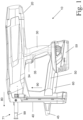
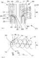
- Fig. 1 shows a driving device 10 for driving a fastening element, for example a nail or bolt, into a surface (not shown) in a side view.
- the driving device 10 has an energy transmission element, not shown, for transmitting energy to the fastening element and a housing 20 in which the energy transmission element and a drive device, also not shown, for transporting the energy transmission element are accommodated.
- the driving device 10 also has a handle 30, a magazine 40 and a bridge 50 connecting the handle 30 to the magazine 40.
- the magazine is not removable.
- a scaffold hook 60 for hanging the driving device 10 on a scaffold or the like and an electrical energy storage device designed as a battery 59 are attached to the bridge 50.
- a trigger 34 and a handle sensor designed as a hand switch 35 are arranged on the handle 30. Aligning the driving device perpendicular to a surface is supported by an alignment aid 45.
- the driving device 10 has a setting channel 99 for guiding the fastening element and a pressing device 71 for detecting a distance of the driving device 10 from a surface, not shown.
- the pressing device 71 comprises a pressing element which is offset relative to the magazine 40 when the driving device 10 is pressed against the surface.
- the pressing element is formed by the setting channel 99.
- the pressing element is arranged next to the setting channel and projects beyond it towards the ground in the unpressed state.
- the magazine 40 is used to transport fastening elements in a transport direction 90 to the setting channel 99.
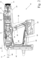
- Fig. 2 shows the driving device 10 with the housing 20 open.
- a drive device 70 for transporting an energy transmission element 75 which is partially hidden in the drawing is accommodated in the housing 20.
- the energy transmission element 75 becomes moved in a fastening direction 80 in order to transmit energy to a fastening element transported from the magazine 40 into the setting channel 99.
- the drive device 70 comprises an electric motor, not shown, for converting electrical energy from the battery 59 into rotational energy, a torque transmission device comprising a gear 41 for transmitting a torque of the electric motor to a motion converter designed as a spindle drive 31, a power transmission device comprising a roller train 26 for transmitting a force from the motion converter to a mechanical energy storage designed as a spring 21 and to transmit a force from the spring to the energy transmission element.
- the drive device for transporting the energy transmission element is operated by means of a flywheel, compressed air, gas or powder combustion.
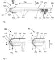
- Fastening elements 110 are inserted into the magazine 140 and are transported into a setting channel 100 in a transport direction 190.
- the fastening elements 110 are designed as nails and define a fastening direction 180 into the drawing plane, so that in 3 and 4 only the heads of the fasteners 110 can be seen.
- the fastening elements 110 are arranged in two rows, which are arranged one behind the other in a transverse direction 170 oriented perpendicular to the transport direction 190 and perpendicular to the fastening direction 180. In exemplary embodiments not shown, the fastening elements are arranged in three or more rows, which are arranged one behind the other in the transverse direction.
- the magazine 140 transports the fastening elements 110 of the two rows alternately into the setting channel.
- the magazine 140 includes a magazine housing 150, which has a first insertion bevel 151 and a second insertion bevel 152.
- the first insertion bevel 151 is inclined to the transport direction 190 and serves to guide the frontmost fastening element 111 in the transport direction 190 3 and 4 each upper row of fastening elements 110 into the setting channel 100.
- the second insertion bevel 152 is also inclined to the transport direction 190 and serves to guide the in the Transport direction 190 of the frontmost fastening element 112 in 3 and 4 each lower row of fastening elements 110 into the setting channel 100 after the frontmost fastening element 111 of the upper row has been set and has left the magazine 140 and the setting channel 100, as in Fig. 4 is shown.
- the magazine housing 150 and thus the first insertion bevel 151 and the second insertion bevel 152 are rigidly connected to the setting channel 100.
- the insertion bevels are formed separately from the magazine or its housing. In any case, the insertion bevels are preferably rigidly connected to the setting channel.
- the magazine 140 has a guide channel 120 for guiding the two rows of fastening elements 110 into the setting channel 100.
- the guide channel 120 opens into the setting channel 100 with an opening 125.
- the opening 125 is in the transverse direction 170 between a first position, which is in Fig. 4 is shown on the left, and a second position, which is in Fig. 4 shown on the right, can be moved back and forth.
- the guide channel 120 is offset from the setting channel and parallel to the fastening direction 180 in the drawing plane of Fig. 3 swivel axis 130 directed inwards is pivotably mounted.
- the pivot axis 130 cuts an imaginary extension of the guide channel 120 counter to the transport direction 190, i.e. in Fig. 3 To the right.
- the guide channel can be displaced in parallel between the corresponding first and second positions.
- the first insertion bevel 151 Aligns the upper row with the setting channel 100 by sliding the front fastening element 111 of the upper row on the first insertion slope 151.
- the second insertion bevel 152 it is advantageously possible for the second insertion bevel 152 to be in Fig. 3 aligns the lower row with the setting channel 100 by sliding the frontmost fastening element 112 of the lower row on the second insertion bevel 152.
- the magazine 140 has a feed element 160, which applies a force 165 to the fastening elements 110 in the transport direction 190 in order to effect the transport of the fastening elements 110.
- the feed element 160 has a plurality of contact surfaces 161, 162 that are offset from one another in the transport direction 190 for contact with one of the several rows of fastening elements 110.
- a first contact surface 161 lies on the in Fig. 3 upper row of fasteners 110, whereas a second contact surface 162 on the in Fig. 3 bottom row of fasteners 110 rests.
- the feed element 160 is movable in the transport direction 190 and guided in a guide rail 195.
- the guide rail 195 is part of the magazine housing 150 or is rigidly connected to the magazine housing 150.
- a spring applies the force to the feed element 160 in the transport direction 190 towards the setting channel 100.
- the feed element 160 is manually moved against the transport direction 190 by a user of the driving device Fig. 3 pushed to the right and released after inserting the fastening elements 110 and / or brought into contact with the fastening elements 110.
- FIG. 5 A magazine 240 is partially shown in a top view.
- Fastening elements 210 are inserted into the magazine 240 and are transported in a transport direction 290 into a setting channel (not shown).
- the fastening elements 210 define a fastening direction 280 into the drawing plane, so that in Fig. 5 only the heads of the fasteners 210 can be seen.
- the fastening elements 210 are arranged in two rows, which are arranged one behind the other in a transverse direction 270 oriented perpendicular to the transport direction 290 and perpendicular to the fastening direction 280.
- the magazine 240 transports the fastening elements 210 of the two rows alternately into the setting channel.
- the magazine 240 includes a magazine housing 250 and a guide channel 220 for guiding the two rows of fastening elements 210 into the setting channel.
- the guide channel 220 can be moved back and forth in the transverse direction 270.
- the magazine 240 has a feed element 260, which applies a force 265 to the fastening elements 210 in the transport direction 290 in order to effect the transport of the fastening elements 210.
- the feed element 260 has exactly one contact surface 261 for contact with only one of the several rows of fastening elements 210.
- the feed element 260 is movable in the transport direction 290 and guided in a guide rail 295.
- the guide rail 295 is part of the magazine housing 250 or is rigidly connected to the magazine housing 250.
- the feed element 260 is arranged offset relative to the guide channel 220 in the fastening direction 280.
- the back and forth movement 222 of the guide channel 220 and the fastening elements 210 guided therein in the transverse direction 270 creates a friction force F R which is directed opposite to the back and forth movement 222 and which must be overcome by the feed element 260 when the fastening elements 210 are transported.
- FIG. 6 A magazine 340 is partially shown in a top view.
- Fastening elements 310 are inserted into the magazine 340 and are transported in a transport direction 390 into a setting channel (not shown).
- the fastening elements 310 define a fastening direction 380 into the drawing plane, so that in Fig. 6 only the heads of the fasteners 310 can be seen.
- the fastening elements 310 are arranged in two rows, which are arranged one behind the other in a transverse direction 370 oriented perpendicular to the transport direction 390 and perpendicular to the fastening direction 380.
- the magazine 340 transports the fastening elements 310 of the two rows alternately into the setting channel.
- the magazine 340 includes a magazine housing 350 and a guide channel 320 for guiding the two rows of fastening elements 310 into the setting channel.
- the guide channel 320 is in the transverse direction 370 between a first position, which is in Fig. 6 is shown above, and a second position, which is in Fig. 6 shown below, can be moved back and forth.
- the magazine 340 has a feed element 360, which applies a force 365 to the fastening elements 310 essentially in the transport direction 390 in order to effect the transport of the fastening elements 310.
- the feed element 360 has a contact surface 361 for contact with the multiple rows of fastening elements 310.
- the feed element 360 is movable in the transport direction 390 and guided in a guide rail 395.
- the guide rail 395 is part of the guide channel 320 or rigidly connected to the guide channel 320. A frictional force between the feed element 360 and the fastening elements 310 in the transverse direction 370 is thereby avoided. For this purpose, the mass of the feed element 360 and the guide rail 395 must also be moved when the guide channel 320 moves back and forth in the transverse direction 370.
- FIG. 7 A magazine 440 is partially shown in a top view.
- Fastening elements 410 are inserted into the magazine 440 and are transported in a transport direction 490 into a setting channel (not shown).
- the fastening elements 410 define a fastening direction 480 into the drawing plane, so that in Fig. 7 just the heads of the Fasteners 410 can be seen.
- the fastening elements 410 are arranged in two rows, which are arranged one behind the other in a transverse direction 470 oriented perpendicular to the transport direction 490 and perpendicular to the fastening direction 480.
- the magazine 440 transports the fastening elements 410 of the two rows alternately into the setting channel.
- the magazine 440 includes a magazine housing 450 and a guide channel 420 for guiding the two rows of fastening elements 410 into the setting channel.
- the guide channel 420 can be moved back and forth in the transverse direction 470.
- the magazine 440 has a feed element 460, which applies a force 465 to the fastening elements 410 essentially in the transport direction 490 in order to effect the transport of the fastening elements 410.
- the feed element 460 has a plurality of contact surfaces 461, 462 that are offset from one another in the transport direction 490 for contact with one of the several rows of fastening elements 410.
- a first contact surface 461 lies on the in Fig.
- the feed element 460 is movable in the transport direction 490 and guided in a guide rail 495.
- the guide rail 495 is part of the guide channel 420 or rigidly connected to the guide channel 420.
- FIG. 8 A magazine 540 is partially shown in a top view.
- Fastening elements 510 are inserted into the magazine 540 and are transported in a transport direction 590 into a setting channel (not shown).
- the fastening elements 510 define a fastening direction 580 into the drawing plane, so that in Fig. 7 only the heads of the fasteners 510 can be seen.
- the fastening elements 510 are arranged in two rows, which are arranged one behind the other in a transverse direction 570 oriented perpendicular to the transport direction 590 and perpendicular to the fastening direction 580.
- the magazine 540 transports the fastening elements 510 of the two rows alternately into the setting channel.
- the magazine 540 includes a magazine housing 550 and a guide channel 520 for guiding the two rows of fastening elements 510 into the setting channel.
- the guide channel 520 can be moved back and forth in the transverse direction 570.
- the magazine 540 has a feed element 560, which applies a force 565 to the fastening elements 510 in the transport direction 590 in order to transport the Fasteners 510 to effect.
- the feed element 560 has a plurality of contact surfaces 561, 562 that are offset from one another in the transport direction 590 for contact with one of the several rows of fastening elements 510.
- a first contact surface 561 lies on the in Fig. 8 upper row of fasteners 510, whereas a second contact surface 562 on the in Fig.
- the feed element 560 is movable in the transport direction 590 and guided in a guide rail 595.
- the guide rail 595 is part of the magazine housing 550 or is rigidly connected to the magazine housing 550.
- the feed element 560 is mounted displaceably relative to the guide rail 595 along the arrows 563, and thus in the transverse direction 570.
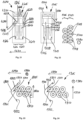
- a setting channel 600 and a magazine 640 are shown twice in a sectional view.
- Fastening elements 610 are inserted into the magazine 640 and are transported in a transport direction 690 out of the drawing plane into the setting channel 600.
- the fastening elements 610 define a fastening direction 680.
- the fastening elements 610 are arranged in two rows, which are arranged one behind the other in a transverse direction 670 oriented perpendicular to the transport direction 690 and perpendicular to the fastening direction 680.
- the magazine 640 transports the fastening elements 610 of the two rows alternately into the setting channel.
- the magazine 640 includes a magazine housing 650 and a guide channel 620 for guiding the two rows of fastening elements 610 into the setting channel 600.
- the guide channel 620 opens into the setting channel 600 with an opening 625.
- the opening 625 is in the transverse direction 670 between a first position, which is in Fig. 9 is shown on the left, and a second position, which is in Fig. 9 shown on the right, can be moved back and forth.
- the guide channel 620 is pivotally mounted about a pivot axis 130 that is offset from the setting channel 600 into the plane of the drawing and oriented parallel to the fastening direction 680.
- the setting channel 600 and the magazine 640 are parts of a driving device, which further comprises a pressing device 671 with a pressing element 672.
- the pressing element 672 has a first force transmission surface 673 for transmitting a force 676 counter to the transverse direction 670 to the guide channel 620 and a second force transmission surface 674 for transmitting a force in the transverse direction 670 to the guide channel 620.
- the guide channel 620 in turn has a first counter surface 677 for transmitting the force 676 counter to the transverse direction 670 and a second counter surface 678 for transmitting the force in the transverse direction 670.
- the pressing element 672 is offset relative to the magazine 640 and thus the setting channel 620 against the fastening direction 680, so that the first force transmission surface 673 comes into contact with the first counter surface 677 and the force 676 acts counter to the transverse direction 670 on the guide channel 620 and ultimately on the fastening elements 610.
- the mouth 625 of the guide channel 620 and the fastening elements 610 are thereby inserted into the in Fig. 9 second position shown on the right moves, so that a frontmost fastening element 611 of the several rows of fastening elements 610 in the transport direction 690 is positioned in the setting channel 600.
- the first force transmission surface 673 acts as a control surface for guiding the frontmost fastening element 611 in the transport direction 690 into the setting channel 600.
- the first counter surface 677 acts as a counter control surface for the controlled movement of the mouth 625 into the second position when the first force transmission surface 673 engages the first counter surface 677.
- a setting channel 700 and a fastening element strip 705 with fastening elements 710 are partially shown in a top view.
- the fastening elements 710 are transported into the setting channel 700 in a magazine (not shown) in a transport direction 190.
- the fastening elements 710 are designed as nails and define a fastening direction 780 into the drawing plane, so that in Fig. 10 only the heads of the fasteners 710 can be seen.
- the fastening elements 710 are arranged in two rows, which are arranged one behind the other in a transverse direction 770 oriented perpendicular to the transport direction 790 and perpendicular to the fastening direction 780.
- a first insertion bevel 751 and a second insertion bevel 752 are rigidly attached to the setting channel 700.
- the first insertion bevel 751 is inclined to the transport direction 790 and serves to guide the frontmost fastening element 711 in the transport direction 790 Fig. 10 upper row of fastening elements 710 in a first direction 753 parallel to the first insertion bevel 751 towards the setting channel 700, at least up to an intermediate position 715 shown broken.
- the desired positioning of the frontmost fastening element 711 in the transport direction 790 in Fig. 10 top row of Fastening elements 710 in the setting channel 700 are then preferably carried out analogously by means of a pressing element Fig.
- the second direction 754 is more inclined relative to the transport direction 790 than the first direction 753, whereby a smaller angle of inclination of the first insertion bevel 751 relative to the transport direction 790 is possible with the same arrangement of the fastening elements 710 in the fastening element strip 705. This may reduce frictional forces between the frontmost fastener 711 and the first insertion bevel 751 and the risk of the fastener strip 705 jamming.
- the second insertion bevel 752 is also inclined to the transport direction 790 and serves to guide the frontmost fastening element 712 in the transport direction 790 Fig. 10 lower row of fastening elements 710 into the setting channel 100 after the frontmost fastening element 711 of the upper row has been set and has left the setting channel 700.
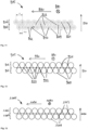
- a fastening element strip 805 is shown in a top view, which comprises two rows 806, 807 of receptacles 809 aligned in a transport direction 890 as well as fastening elements 810 recorded in the receptacles 809 and defining a fastening direction 880 directed into the plane of the drawing.
- the rows 806, 807 of receptacles 809 and thus of fastening elements 810 are arranged one behind the other in a transverse direction 870 oriented perpendicular to the transport direction 890 and perpendicular to the fastening direction 880.
- the fastener strip 805 has a plurality of first connecting webs 821, each of which connects two adjacent receptacles within a first row 806 of receptacles 809 to one another. Furthermore, the fastener strip 805 has a plurality of second connecting webs 822, each of which connects two adjacent receptacles within a second row 807 of receptacles 809 to one another. Furthermore, the fastening element strip 805 has a plurality of third connecting webs 823, each of which connects a receptacle of the first row 806 to a receptacle of the second row 807.
- Each receptacle in the first row 806 is connected to an adjacent receptacle in the second row 807 directly via a third connecting web 823.
- the first connecting webs 821 and the second connecting webs 822 are aligned parallel to the transport direction 890, whereas the third connecting webs 823 are aligned inclined both with respect to the transport direction 890 and with respect to the transverse direction 870.
- each receptacle is arranged offset from all other receptacles in rows 806, 807 in the transport direction 890.
- the offset P/2 measured in the transport direction 890 between two recordings immediately following one another in the transport direction 890 is the same for all recordings, namely exactly half as large as the offset P between two immediately following recordings within one of the rows 806, 807.
- the first connecting webs 821, second connecting webs 822, third connecting webs 823 and receptacles 809 are formed together as an integral part, which consists of plastic and is produced, for example, by means of an injection molding process.
- each receptacle in the first row 806 is rigidly connected to at least one receptacle in the second row 807.
- the connecting webs 821, 822, 823 By appropriately selecting the material and dimensions of the connecting webs 821, 822, 823, a desired rigidity of the fastening element strip 805 can be achieved.
- the two or more rows of receptacles are first manufactured separately and then connected to one another, for example locked, welded or glued together.
- the receptacles and/or the connecting webs consist at least partially of plastic, metal, paper or several of the materials mentioned.
- a fastening element strip 905 is shown in a top view, which comprises two rows 906, 907 of receptacles 909 aligned in a transport direction 990 as well as fastening elements, not shown, recorded in the receptacles 909 and defining a fastening direction 980 directed into the plane of the drawing.
- the rows 906, 907 of receptacles 909 are arranged one behind the other in a transverse direction 970 oriented perpendicular to the transport direction 990 and perpendicular to the fastening direction 980.
- the fastener strip 905 has a plurality of first connecting webs 921, each of which has two adjacent receptacles within a first row 906 Connect recordings 909 together. Furthermore, the fastener strip 905 has a plurality of second connecting webs 922, each of which connects two adjacent receptacles within a second row 907 of receptacles 909 to one another. Furthermore, the fastening element strip 905 has a plurality of third connecting webs 923, each of which connects a receptacle of the first row 906 to a receptacle of the second row 907.
- Each receptacle in the first row 906 is connected to an adjacent receptacle in the second row 907 directly via a third connecting web 923.
- the first connecting webs 921 and the second connecting webs 922 are aligned parallel to the transport direction 990, whereas the third connecting webs 923 are aligned perpendicular to the transport direction 990 and parallel to the transverse direction 970.
- each receptacle is offset by the same amount from all other receptacles in rows 906, 907 in the transport direction 890.
- a fastening element strip 1005 is shown in a top view, which includes two rows 1006, 1007 of receptacles 1009 aligned in a transport direction 1090 as well as fastening elements (not shown) recorded in the receptacles 1009 and defining a fastening direction 1080 directed into the plane of the drawing.
- the rows 1006, 1007 of receptacles 1009 are arranged one behind the other in a transverse direction 1070 oriented perpendicular to the transport direction 1090 and perpendicular to the fastening direction 1080.
- the fastening element strip 1005 has a plurality of connecting webs 1023, each of which connects a receptacle in the first row 1006 to a receptacle in the second row 1007.
- Each receptacle in the first row 1006 is connected to an adjacent receptacle in the second row 1007 directly via a connecting web 1023.
- each recording of the first row 1006 or the second row 1007 is only indirectly connected to an adjacent recording of the same row 1006, 1007, namely via a recording of the other row 1007, 1006. This allows two adjacent recordings of the same row 1006, 1007 move towards each other until they touch.
- the rigidity of the fastener strip 1005 is therefore reduced.
- the fastener strip 1005 is inserted into a guide channel 1020 of a magazine 1040 of a driving device, not shown, and is acted upon by a feed element, not shown, with a force 1065 in the transport direction, as in Fig. 14 shown, then the fastener strip 1005 can be compressed in the transport direction 1005, so that its width in the transverse direction 1070 increases. Before compression, however, the fastener strip 1005 has a smaller width in the transverse direction 1070 and is easier to insert into or remove from the magazine 1040.
- a section of a fastener strip 1105 is shown, namely a top view at the bottom and a cross section at the top.
- the fastener strip 1105 has a first receptacle 1126 for a fastener, not shown, and a second receptacle 1127 for another fastener, not shown.
- the receptacles 1126, 1127 define a fastening direction 1180.
- the receptacle 1126 comprises a hollow shaft 1128 and two guide washers 1129, which guide the fastening element extending through the shaft 1128 and the guide washers 1129 in a setting channel, not shown, while the fastening element is in a substrate is driven in.
- the fastener strip 1105 includes a connecting web 1124, which directly connects the receptacles 1126, 1127 to one another.
- the connecting web 1124 has a predetermined breaking point 1131, which is aligned parallel to the fastening direction 1180 and is designed, for example, as a linear material taper. This simplifies the separation of the first receptacle 1126 and the fastening element accommodated therein from the second receptacle 1127 and thus from the remaining fastener strip 1105.
- a section of a fastener strip 1205 is shown, namely in a top view at the bottom and in a cross section at the top.
- the fastener strip 1205 has a first receptacle 1226 for a fastener, not shown, and a second receptacle 1227 for another fastener, not shown.
- the receptacles 1226, 1227 define a fastening direction 1280.
- the fastener strip 1205 comprises two connecting webs 1224, which connect the receptacles 1226, 1227 directly to one another.
- Each of the connecting bridges 1224 has a predetermined breaking point 1231, which is aligned parallel to the fastening direction 1280 and is designed as a linear material taper.
- a section of a fastener strip 1305 is shown, namely a top view at the bottom and a cross section at the top.
- the fastener strip 1305 has a first receptacle 1326 for a fastener, not shown, and a second receptacle 1327 for another fastener, not shown.
- the receptacles 1326, 1327 define a fastening direction 1380.
- the fastener strip 1305 comprises two connecting webs 1324, which connect the receptacles 1326, 1327 directly to one another.
- Each of the connecting webs 1324 has a predetermined breaking point 1331, which is aligned perpendicular to the fastening direction 1380 and is designed as a linear material taper.
- a section of a fastener strip 1405 is shown, namely in a top view at the bottom and in a cross section at the top.
- the fastener strip 1405 has a first receptacle 1426 for a fastener, not shown, and a second receptacle 1427 for another fastener, not shown.
- the receptacles 1426, 1427 define a fastening direction 1480.
- the fastener strip 1405 includes a connecting web 1424, which directly connects the receptacles 1426, 1427 to one another.
- the connecting web 1424 has a predetermined breaking point 1431, which is aligned perpendicular to the fastening direction 1380 and is designed as a linear material taper.
- a fastening element strip 1505 is partially shown in a top view, which comprises two rows 1506, 1507 of receptacles 1509 aligned in a transport direction 1590 as well as fastening elements 1510 recorded in the receptacles 1509 and defining a fastening direction 1580 directed into the plane of the drawing.
- the rows 1506, 1507 of receptacles 1509 and thus of fastening elements 1510 are arranged one behind the other in a transverse direction 1570 oriented perpendicular to the transport direction 1590 and perpendicular to the fastening direction 1580.
- Each of the receptacles 1509 is arranged offset from all other receptacles in the rows 1506, 1507 in the transport direction 1590.
- the offset P/2 measured in the transport direction 1590 between two immediately successive ones in the transport direction 1590 Recordings is the same for all recordings, namely exactly half as large as the offset P between two immediately consecutive recordings within one of the rows 1506, 1507.
- a shortest connecting line 1532 between two immediately following recordings of different rows 1506, 1507 is 1570 ⁇ m compared to the transverse direction inclined at an angle ⁇ .
- the fastener strip 1505 is inserted into a magazine 1540, which transports the fasteners 1510 one after the other into a setting channel 1500.
- the magazine 1540 includes a magazine housing 1550, which has a first insertion bevel 1551 and a second insertion bevel 1552.
- the first insertion bevel 1551 and the second insertion bevel 1552 are each inclined by an angle ⁇ relative to the transverse direction 1570.
- the magazine 1540 has a guide channel 1520 for guiding the fastening elements 1510 into the setting channel 1500.
- the guide channel 1520 is mounted so as to be pivotable by a pivot angle ⁇ about a pivot axis, not shown, which is offset from the setting channel and aligned parallel to the fastening direction 1580.
- the largest possible inclination angle ⁇ is advantageous.
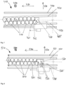
- FIG. 21 A magazine 1640 and a fastener strip 1605 are shown in a sectional view.
- the magazine includes a guide channel 1620 into which the fastener strip 1605 is inserted.
- the fastening element strip 1605 comprises two rows 1606, 1607 of receptacles 1609 as well as fastening elements 1610 received in the receptacles 1609 and defining a fastening direction 1680.
- the rows 1606, 1607 of receptacles 1609 and thus of fastening elements 1610 are arranged one behind the other in a transverse direction 1670.
- Each of the receptacles 1609 comprises a hollow shaft 1628 and two guide washers 1629, which guide the fastening element extending through the shaft 1628 and the guide washers 1629 in a setting channel, not shown, while the Fastening element is driven into a surface. Heads 1618 of the fastening elements 1610 may also serve for such guidance.
- the guide channel 1620 includes a first guide groove 1616 for the first row 1606 and a second guide groove 1617 for the second row 1607.
- the guide channel 1620 has a first guide projection 1636 assigned to the first row 1606 and a the second guide projection 1637 assigned to the second row 1607.
- the guide projections 1636, 1637 engage in a space between the guide disks 1629.
- the guide channel 1620 has a first guide recess 1646 assigned to the first row 1606 and a second guide recess 1647 assigned to the second row 1607.
- the guide recesses 1646, 1647 each accommodate one of the guide rondels 1629.
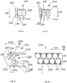
- FIG. 22 A magazine 1740 and a fastener strip 1705 are shown on the left in a sectional view and on the right in a top view.
- the magazine includes a guide channel 1720 into which the fastener strip 1705 is inserted.
- the fastening element strip 1705 comprises two rows 1706, 1707 of receptacles 1709 as well as fastening elements 1710 received in the receptacles 1709 and defining a fastening direction 1780.
- Each of the receptacles 1709 comprises a hollow shaft 1728 and two guide washers 1729, which extend through the shaft 1728 and the guide washers 1729 guide the fastening element 1710 extending through it in a setting channel, not shown, while the fastening element is driven into a substrate.
- the guide channel 1720 comprises a first guide groove 1716 and a second guide groove 1717.
- the guide rondelle 1729 which points in the fastening direction, has an extension 1748, which engages in the respective guide groove 1716, 1717 and guides the fastening elements 1710 in the respective guide groove 1716, 1717 improved.
- the extensions 1748 are preferably each designed as two flats.
- a setting channel 1800 and a fastening element strip 1805 with fastening elements 1810 are partially shown in a top view.
- the fasteners 1810 are stored in a magazine, not shown Transport direction 1890 transported into the setting channel 1800.
- the fastening elements 1810 are designed as nails and define a fastening direction 1880 into the drawing plane, so that in Fig. 23 only the heads of the fasteners 1810 can be seen.
- the fastening elements 1810 are arranged in two rows, which are arranged one behind the other in a transverse direction 1870 oriented perpendicular to the transport direction 1890 and perpendicular to the fastening direction 1880.
- a first insertion bevel 1851 and a second insertion bevel 1852 are rigidly attached to the setting channel 1800.
- the first insertion bevel 1851 is inclined to the transport direction 1890 and serves to guide the frontmost fastening element 1811 in the transport direction 1890 Fig. 23 upper row of fastening elements 1810 towards the setting channel 1800, in that the receptacle 1841 of the frontmost fastening element 1811 touches the first insertion bevel 1851 in a line and in particular slides tangentially over the first insertion bevel 1851.
- the line-shaped contact 1829 is aligned parallel to the fastening direction.
- a setting channel 1900 and a fastening element strip 1905 with fastening elements 1910 are partially shown in a top view.
- the fastening elements 1910 are transported into the setting channel 1900 in a magazine (not shown) in a transport direction 1990.
- the fastening elements 1910 are designed as nails and define a fastening direction 1980 into the drawing plane, so that in Fig. 24 only the heads of the 1910 fasteners can be seen.
- the fastening elements 1910 are arranged in two rows, which are arranged one behind the other in a transverse direction 1970 oriented perpendicular to the transport direction 1990 and perpendicular to the fastening direction 1980.
- a first insertion bevel 1951 and a second insertion bevel 1952 are rigidly attached to the setting channel 1900.
- the first insertion bevel 1951 is inclined to the transport direction 1990 and serves to guide the frontmost fastening element 1911 in the transport direction 1990 Fig. 24 upper row of fastening elements 1910 towards the setting channel 1900 by the receptacle 1941 of the frontmost fastening element 1911 touching the first insertion bevel 1951 and sliding over the first insertion bevel 1951.
- the surface-shaped contact 1929 is in particular flat and aligned parallel to the fastening direction 1980.
- FIG. 25 an insertion bevel 2051 and a fastener strip 2005 with fasteners 2010 are partially shown in a sectional view.
- the fastening elements 2010 define a fastening direction 2080 and are recorded and held in receptacles 2009 of the fastening element strip 2005.
- the insertion bevel 2051 serves to guide the fastening element strip 2005 in that the receptacle 2041 of a frontmost fastening element 2011 touches the insertion bevel 2051 flat and slides over the first insertion bevel 2051.
- the surface-shaped contact 2029 is in particular flat and aligned parallel to the fastening direction 2080. In addition, the contact 2029 extends over the entire length of the receptacle 2041 in the fastening direction 2080.
- FIG. 26 an insertion bevel 2151 and a fastener strip 2105 with fasteners 2110 are partially shown in a sectional view.
- the fastening elements 2110 define a fastening direction 2180 and are received and held in receptacles 2109 of the fastening element strip 2105.
- the insertion bevel 2151 serves to guide the fastening element strip 2105 in that the receptacle 2141 of a frontmost fastening element 2111 touches the insertion bevel 2151 flat and slides over the first insertion bevel 2151.
- the surface-shaped contact 2129 is in particular flat and aligned parallel to the fastening direction 2180.
- the insertion bevel 2151 and thus the contact 2129 are interrupted along the fastening direction 2080.
- a setting channel 2200 and a magazine 2240 with a fastening element strip 2205 arranged therein with fastening elements 2210 are partially shown in a top view.
- the fastening elements 2210 are transported in the magazine 2240 in a transport direction 2290 into the setting channel 2200.
- the fastening elements 2210 are designed as nails and define a fastening direction 2280 into the drawing plane, so that in Fig. 27 only the heads of the fasteners 2210 can be seen.
- the fastening elements 2210 are arranged in two rows, which are arranged one behind the other in a transverse direction 2270 oriented perpendicular to the transport direction 2290 and perpendicular to the fastening direction 2280.
- a first insertion bevel 2251 and a second insertion bevel 2252 are rigidly attached to the setting channel 2200.
- the first insertion bevel 2251 is inclined to the transport direction 2290 and serves to guide the frontmost fastening element 2211 in the transport direction 2290 Fig. 27 upper row of fastening elements 2210 towards the setting channel 2200.
- the frontmost fastening element 2211 in the transport direction 2290 in Fig. 27 The top row also touches a guide channel 2220 of the magazine 2240 at a point 2261, whereas the frontmost fastening element 2212 in the transport direction 2290 in Fig. 27 lower row touches the guide channel 2220 at a second contact point 2262.
- a distance A measured in the transport direction 2290 between the contact points 2261, 2262 is relatively small.
- a force 2265 which is exerted on the fastening element strip 2205, for example by a feed element (not shown) of the magazine 2240, causes a relatively large torque 2263 on the remaining fastening elements 2210, which under certain circumstances can lead to the fastening element strip 2205 jamming.
- Fig. 28 and 29 are a setting channel 2300 and a magazine 2340 with a fastener strip 2305 arranged therein in a top view and in Fig. 30 shown in a sectional view.
- the fastening element strip 2305 comprises two rows 2306, 2307 of receptacles 2309 aligned in a transport direction 2390 as well as fastening elements 2310 recorded in the receptacles 2309 and defining a fastening direction 2380.
- the rows 2306, 2307 of receptacles 2309 are in a direction perpendicular to the transport direction 2390 and perpendicular to the fastening direction 2380 oriented transverse direction 2370 arranged one behind the other.
- a first insertion bevel 2351 and a second insertion bevel 2352 are rigidly attached to the setting channel 2300.
- the first insertion bevel 2351 is inclined to the transport direction 2390 and serves to guide the frontmost fastening element 2311 in the transport direction 2390 Fig. 29 upper row of fastening elements 2310 towards the setting channel 2300.
- the fastener strip 2305 has support projections 2371, each with a contact surface 2372 for abutment of the fastener strip 2305 on a guide channel 2320 of the magazine 2340.
- the supporting projections 2371 each protrude from a receptacle 2309 of a row 2306, 2307 and are offset in the transport direction 2390 relative to the fastening element 2310 received in the receptacle 2309. Due to the offset in the transport direction 2390, the support projections 2371 support the fastener strip 2305 in the guide channel against tilting by one in the tilting axis facing the fastening direction 2380 and thus counteract a corresponding torque.
- the frontmost fastening element 2311 in the transport direction 2390 in Fig. 29 The upper row is supported on the guide channel 2320 of the magazine 2340 at a point 2361, whereas the frontmost fastening element 2312 in the transport direction 2390 is the one in Fig. 29 lower row is supported on the guide channel 2320 at a second contact point 2362.
- a distance A 'measured in the transport direction 2390 between the contact points 2361, 2362 is larger, in particular significantly larger, than an offset between the fastening elements 2311, 2312 in the transport direction 2390.
- a force 2365 which is exerted on the fastening element strip 2305, for example by a feed element (not shown) of the magazine 2340, causes a relatively small torque 2363 on the remaining fastening elements 2310, whereby the risk of the fastening element strip 2305 jamming is reduced.
- the frontmost support projection 2381 of the upper row of fastening elements 2310 and the first insertion bevel 2351 are arranged one behind the other in the fastening direction 2380 and preferably overlap in a projection in the fastening direction 2380.
- a fastener strip 2405 is shown in a top view.
- the fastening element strip 2405 comprises two rows 2406, 2407 of receptacles 2409 aligned in a transport direction 2490 as well as fastening elements, not shown, recorded in the receptacles 2409, which define a fastening direction 2480 into the plane of the drawing.
- the rows 2406, 2407 of receptacles 2409 are arranged one behind the other in a transverse direction 2470 oriented perpendicular to the transport direction 2490 and perpendicular to the fastening direction 2480.
- the fastener strip 2405 has support projections 2471, each with a contact surface 2472 for abutment of the fastener strip 2405 on a guide channel, not shown, of a magazine of a driving device.
- the support projections 2471 each protrude from a receptacle 2409 of a row 2406, 2407 and are offset in the transport direction 2490 relative to the fastening element accommodated in the receptacle 2409. Support by the offset in the transport direction 2490 the support projections 2471 prevent the fastening element strip 2405 in the guide channel from tilting about a tilt axis pointing in the fastening direction 2480.
Landscapes
- Engineering & Computer Science (AREA)
- Mechanical Engineering (AREA)
- General Engineering & Computer Science (AREA)
- Portable Nailing Machines And Staplers (AREA)
- Slide Fasteners (AREA)
- Slide Fasteners, Snap Fasteners, And Hook Fasteners (AREA)
- Package Frames And Binding Bands (AREA)
- Basic Packing Technique (AREA)
- Supply And Installment Of Electrical Components (AREA)
Claims (12)
- Procédé permettant d'enfoncer des éléments de fixation dans un substrat au moyen d'un dispositif (10), lequel est pourvu d'un canal de pose (99), d'un élément de transmission d'énergie (75) déplaçable dans un sens de fixation (80) dans le canal de pose pour la transmission d'énergie à l'un des éléments de fixation respectivement, et d'un magasin (40) pour un transport des éléments de fixation dans un sens de transport (90) jusqu'au canal de pose (99), dans lequel le magasin (40) transporte simultanément plusieurs rangées d'éléments de fixation, lesquelles sont disposées les unes derrière les autres dans un sens transversal (170) perpendiculaire au sens de transport (90) et perpendiculaire au sens de fixation (80), afin de transporter en alternance des éléments de fixation de différentes rangées des plusieurs rangées d'éléments de fixation dans le canal de pose (99), dans lequel le dispositif (10) présente un biseau d'insertion (151), incliné par rapport au sens de transport (90), pour le guidage de l'élément de fixation, le plus à l'avant dans le sens de transport, des plusieurs rangées d'éléments de fixation dans le canal de pose (99), caractérisé en ce que le biseau d'insertion (151) aligne la rangée de l'élément de fixation le plus à l'avant des plusieurs rangées d'éléments de fixation sur le canal de pose (99).
- Procédé selon la revendication 1, dans lequel le magasin (40) présente un élément d'avancement (160), lequel soumet les plusieurs rangées d'éléments de fixation à une force dans le sens de transport (90), dans lequel l'élément d'avancement (160) présente plusieurs surfaces d'appui (161, 162) décalées les unes par rapport aux autres dans le sens de transport pour un appui contre respectivement l'une des plusieurs rangées d'éléments de fixation.
- Procédé selon l'une des revendications précédentes, dans lequel le dispositif (10) présente un élément de pression (672) qui est décalé par rapport au magasin (40) lors d'une pression du dispositif (10) contre le substrat, et qui présente une surface de transmission de force (673), laquelle transmet une force à l'élément de fixation, le plus à l'avant dans le sens de transport (90), des plusieurs rangées d'éléments de fixation vers le canal de pose (99).
- Procédé selon l'une des revendications précédentes, dans lequel le magasin (40) présente un canal de guidage (120) pour le guidage des plusieurs rangées d'éléments de fixation, dans lequel le canal de guidage (120) débouche par un débouché (125) dans le canal de pose (99), dans lequel le débouché (125) est déplacé en va-et-vient entre une première position et une deuxième position dans le sens transversal (170).
- Procédé selon les revendications 3 et 4, dans lequel le canal de guidage (120) présente une surface de commande conjuguée (677), laquelle commande le débouché (125) dans la première ou la deuxième position, lorsque la surface de transmission de force (673) de l'élément de pression (672) vient en prise avec la surface de commande conjuguée (677).
- Procédé selon l'une des revendications 4 et 5, dans lequel le canal de guidage (120) est pivoté autour d'un axe de pivotement (130) décalé en particulier parallèlement par rapport au canal de pose (99).
- Procédé selon la revendication 6, dans lequel l'axe de pivotement (130) croise le canal de guidage (120) ou un prolongement imaginaire du canal de guidage dans le sens de transport (90) ou en sens inverse à celui-ci.
- Bande d'éléments de fixation (805) pour une utilisation dans un dispositif permettant d'enfoncer des éléments de fixation dans un substrat, comportant plusieurs rangées (806, 807), alignées dans un sens de transport (890), de logements (809) pour éléments de fixation ainsi que des éléments de fixation (710) logés dans les logements (809) et définissant un sens de fixation (880), dans laquelle les rangées de logement sont disposées les unes derrière les autres dans un sens transversal (870) orienté perpendiculairement au sens de transport (890) et perpendiculairement au sens de fixation (880), et comportant une nervure de liaison (821), qui relie l'un à l'autre un logement (809) d'une première rangée (806) des plusieurs rangées à un logement (809) d'une deuxième rangée (807) des plusieurs rangées, caractérisée en ce que chaque logement (809) est décalé par rapport à tous les autres logements des plusieurs rangées (806, 807) de logements dans le sens de transport (890).
- Bande d'éléments de fixation selon la revendication 8, dans laquelle le décalage, mesuré dans le sens de transport (890), entre deux logements (809) consécutifs dans le sens de transport est identique pour sensiblement tous les logements.
- Bande d'éléments de fixation selon l'une des revendications 8 et 9, dans laquelle chaque logement (809) de la première rangée (806) est relié à un logement adjacent (809) d'une deuxième rangée (807) directement par le biais d'une nervure de liaison (821).
- Bande d'éléments de fixation selon l'une des revendications 8 à 10, dans laquelle la nervure de liaison (821) présente un point destiné à la rupture (1131) pour une séparation d'au moins l'un des logements (809) dans le dispositif permettant d'enfoncer des éléments de fixation dans un substrat.
- Bande d'éléments de fixation selon l'une des revendications 8 à 11, la bande d'éléments de fixation (2305) présentant une saillie de support (2371) comportant une surface d'appui (2372) pour un appui de la bande d'éléments de fixation contre un canal de guidage d'un magasin du dispositif permettant d'enfoncer des éléments de fixation dans un substrat, la saillie de support (2371) dépassant d'un logement (2309) d'une rangée la plus à l'extérieur des plusieurs rangées et étant décalée dans le sens de transport (2390) par rapport à un élément de fixation (2310) logé dans le logement (2309).
Applications Claiming Priority (2)
| Application Number | Priority Date | Filing Date | Title |
|---|---|---|---|
| EP16204199.0A EP3335836A1 (fr) | 2016-12-15 | 2016-12-15 | Dispositif d'enfoncement et bandes d'éléments de fixation |
| PCT/EP2017/081514 WO2018108630A1 (fr) | 2016-12-15 | 2017-12-05 | Dispositif d'enfoncement et bande d'éléments de fixation |
Publications (3)
| Publication Number | Publication Date |
|---|---|
| EP3554763A1 EP3554763A1 (fr) | 2019-10-23 |
| EP3554763B1 true EP3554763B1 (fr) | 2024-03-13 |
| EP3554763C0 EP3554763C0 (fr) | 2024-03-13 |
Family
ID=57570166
Family Applications (2)
| Application Number | Title | Priority Date | Filing Date |
|---|---|---|---|
| EP16204199.0A Withdrawn EP3335836A1 (fr) | 2016-12-15 | 2016-12-15 | Dispositif d'enfoncement et bandes d'éléments de fixation |
| EP17807889.5A Active EP3554763B1 (fr) | 2016-12-15 | 2017-12-05 | Dispositif d'enfoncement et bandes d'éléments de fixation |
Family Applications Before (1)
| Application Number | Title | Priority Date | Filing Date |
|---|---|---|---|
| EP16204199.0A Withdrawn EP3335836A1 (fr) | 2016-12-15 | 2016-12-15 | Dispositif d'enfoncement et bandes d'éléments de fixation |
Country Status (13)
| Country | Link |
|---|---|
| US (1) | US11110574B2 (fr) |
| EP (2) | EP3335836A1 (fr) |
| JP (1) | JP2020501922A (fr) |
| KR (1) | KR20190095393A (fr) |
| CN (1) | CN110177657B (fr) |
| AU (1) | AU2017375366A1 (fr) |
| BR (1) | BR112019011803A2 (fr) |
| CA (1) | CA3047040A1 (fr) |
| ES (1) | ES2973976T3 (fr) |
| PL (1) | PL3554763T3 (fr) |
| RU (1) | RU2019121885A (fr) |
| TW (1) | TWI695763B (fr) |
| WO (1) | WO2018108630A1 (fr) |
Families Citing this family (1)
| Publication number | Priority date | Publication date | Assignee | Title |
|---|---|---|---|---|
| EP4126461A4 (fr) | 2020-03-25 | 2024-09-25 | Milwaukee Electric Tool Corporation | Dispositif d'entraînement d'élément de fixation alimenté en énergie |
Citations (6)
| Publication number | Priority date | Publication date | Assignee | Title |
|---|---|---|---|---|
| GB1072132A (en) * | 1963-09-17 | 1967-06-14 | Anstalt Fuer Montage Technik | Shearing rings for use with fasteners to be driven into fibrous material |
| US4011785A (en) * | 1971-06-16 | 1977-03-15 | Bliss & Laughlin Ind., Inc. | Nail and powered nailer |
| US4221153A (en) * | 1978-08-02 | 1980-09-09 | Swingline, Inc. | Corrugated fastener and strip of fasteners |
| US4367973A (en) * | 1981-04-13 | 1983-01-11 | Simpson Manufacturing Co., Inc. | Structural strap tie |
| DE3308630A1 (de) * | 1983-03-11 | 1984-09-13 | Signode Corp., Glenview, Ill. | Nagelmagazinierungseinheit |
| EP1298332A2 (fr) * | 2001-09-24 | 2003-04-02 | Illinois Tool Works Inc. | Ruban de chargement enroulé pour cloueuse pneumatique |
Family Cites Families (23)
| Publication number | Priority date | Publication date | Assignee | Title |
|---|---|---|---|---|
| US2909780A (en) * | 1957-06-04 | 1959-10-27 | Fastener Corp | Magazine construction |
| DE2042768C3 (de) * | 1970-08-28 | 1981-01-29 | Hilti Ag, Schaan (Liechtenstein) | Mit Nägeln bestücktes Magazin für ein pulverkraftbetriebenes Setzgerät |
| US4011758A (en) | 1973-12-26 | 1977-03-15 | Texas Instruments Incorporated | Magnetostrictive pressure transducer |
| US4106618A (en) * | 1975-12-15 | 1978-08-15 | Haytayan Harry M | Nail assemblies |
| DE3606901A1 (de) * | 1986-03-03 | 1987-09-10 | Hilti Ag | Nagelstreifen |
| DE3806624A1 (de) * | 1988-03-02 | 1989-09-14 | Hilti Ag | Traegerstreifen |
| DE19707235A1 (de) * | 1997-02-24 | 1998-08-27 | Hilti Ag | Setzgerät mit Magazin für Befestigungselemente |
| US5927585A (en) * | 1997-12-17 | 1999-07-27 | Senco Products, Inc. | Electric multiple impact fastener driving tool |
| DE19831060A1 (de) * | 1998-07-13 | 2000-01-20 | Hilti Ag | Setzgerät mit Nagelmagazin |
| TW426984B (en) | 1999-10-16 | 2001-03-21 | Vanguard Int Semiconduct Corp | Method for producing multi-level contacts |
| EP1207017B1 (fr) * | 2000-11-16 | 2006-08-09 | Max Co., Ltd. | Mécanisme d'alimentation de clous connectés en série pour une machine à clouer |
| JP2003094354A (ja) * | 2001-09-27 | 2003-04-03 | Max Co Ltd | 釘打ち機の釘マガジン |
| US6814231B2 (en) | 2002-01-23 | 2004-11-09 | Illinois Tool Works Inc. | Strip of collated fasteners for fastener-driving tool |
| US7021462B2 (en) * | 2002-12-18 | 2006-04-04 | Powers Fasteners, Inc. | Fastener carrier assembly and method of use |
| US20040118720A1 (en) * | 2002-12-18 | 2004-06-24 | Powers Fasteners, Inc. | Fastener carrier assembly and method of use |
| WO2008049062A1 (fr) * | 2006-10-20 | 2008-04-24 | Stanley Fastening Systems, Lp | Dispositif d'entraînement d'éléments de fixation avec des mécanismes permettant de limiter le mouvement des clous |
| DE102006035459A1 (de) * | 2006-11-27 | 2008-05-29 | Hilti Ag | Handgeführtes Eintreibgerät |
| TWI440774B (zh) * | 2007-11-06 | 2014-06-11 | Max Co Ltd | 連結扣件組合 |
| DE102009001790B4 (de) * | 2009-03-24 | 2014-01-16 | Hilti Aktiengesellschaft | Befestigungselemente-Magazinstreifen |
| CN103085030B (zh) * | 2012-12-29 | 2015-09-02 | 台州市大江实业有限公司 | 射钉枪的钉匣 |
| CN203680238U (zh) * | 2014-01-25 | 2014-07-02 | 杨敏婷 | 一种用于射钉枪上夹持射钉的塑料排条 |
| CN208342755U (zh) * | 2018-03-09 | 2019-01-08 | 杭州职业技术学院 | 一种图钉收纳及省力装置 |
| CN209682106U (zh) * | 2019-02-28 | 2019-11-26 | 重庆布莱沃工贸有限公司 | 一种专用异形连接带 |
-
2016
- 2016-12-15 EP EP16204199.0A patent/EP3335836A1/fr not_active Withdrawn
-
2017
- 2017-11-13 TW TW106139156A patent/TWI695763B/zh active
- 2017-12-05 RU RU2019121885A patent/RU2019121885A/ru not_active Application Discontinuation
- 2017-12-05 WO PCT/EP2017/081514 patent/WO2018108630A1/fr not_active Ceased
- 2017-12-05 US US16/469,697 patent/US11110574B2/en active Active
- 2017-12-05 KR KR1020197020492A patent/KR20190095393A/ko not_active Ceased
- 2017-12-05 PL PL17807889.5T patent/PL3554763T3/pl unknown
- 2017-12-05 JP JP2019532703A patent/JP2020501922A/ja active Pending
- 2017-12-05 EP EP17807889.5A patent/EP3554763B1/fr active Active
- 2017-12-05 CN CN201780083586.4A patent/CN110177657B/zh active Active
- 2017-12-05 ES ES17807889T patent/ES2973976T3/es active Active
- 2017-12-05 CA CA3047040A patent/CA3047040A1/fr not_active Abandoned
- 2017-12-05 AU AU2017375366A patent/AU2017375366A1/en not_active Abandoned
- 2017-12-05 BR BR112019011803-9A patent/BR112019011803A2/pt not_active Application Discontinuation
Patent Citations (6)
| Publication number | Priority date | Publication date | Assignee | Title |
|---|---|---|---|---|
| GB1072132A (en) * | 1963-09-17 | 1967-06-14 | Anstalt Fuer Montage Technik | Shearing rings for use with fasteners to be driven into fibrous material |
| US4011785A (en) * | 1971-06-16 | 1977-03-15 | Bliss & Laughlin Ind., Inc. | Nail and powered nailer |
| US4221153A (en) * | 1978-08-02 | 1980-09-09 | Swingline, Inc. | Corrugated fastener and strip of fasteners |
| US4367973A (en) * | 1981-04-13 | 1983-01-11 | Simpson Manufacturing Co., Inc. | Structural strap tie |
| DE3308630A1 (de) * | 1983-03-11 | 1984-09-13 | Signode Corp., Glenview, Ill. | Nagelmagazinierungseinheit |
| EP1298332A2 (fr) * | 2001-09-24 | 2003-04-02 | Illinois Tool Works Inc. | Ruban de chargement enroulé pour cloueuse pneumatique |
Also Published As
| Publication number | Publication date |
|---|---|
| EP3554763A1 (fr) | 2019-10-23 |
| WO2018108630A1 (fr) | 2018-06-21 |
| AU2017375366A1 (en) | 2019-07-04 |
| US11110574B2 (en) | 2021-09-07 |
| RU2019121885A (ru) | 2021-01-15 |
| BR112019011803A2 (pt) | 2019-10-29 |
| CN110177657A (zh) | 2019-08-27 |
| US20200078914A1 (en) | 2020-03-12 |
| CA3047040A1 (fr) | 2018-06-21 |
| KR20190095393A (ko) | 2019-08-14 |
| EP3335836A1 (fr) | 2018-06-20 |
| CN110177657B (zh) | 2022-10-18 |
| PL3554763T3 (pl) | 2024-09-23 |
| TW201827171A (zh) | 2018-08-01 |
| EP3554763C0 (fr) | 2024-03-13 |
| JP2020501922A (ja) | 2020-01-23 |
| ES2973976T3 (es) | 2024-06-25 |
| RU2019121885A3 (fr) | 2021-09-07 |
| TWI695763B (zh) | 2020-06-11 |
Similar Documents
| Publication | Publication Date | Title |
|---|---|---|
| DE2149951C2 (de) | Heftklammer für weiches Verpackungsmaterial | |
| DE69532738T2 (de) | Handbetätigte Befestigungsvorrichtung | |
| DE2120447B2 (de) | Chirurgisches Instrument zum Herumlegen von Klammern zum Abbinden rohrförmiger organischer Gebilde | |
| DE102007000025A1 (de) | Handgeführtes Setzgerät | |
| DE2534178B1 (de) | Handbedienter, tragbarer hefter, insbesondere fuer buerozwecke | |
| DE1946587C3 (de) | Magazin an einem Nagler für kopflose Nägel | |
| DE3038565C2 (de) | Heftapparat | |
| DE3780333T2 (de) | Eintreibgeraet fuer die blechspitzen des rahmenmachers und glasers. | |
| EP1245860B1 (fr) | Dispositif de fixation d'agrafes de jonction de courroie à des courroies transporteuses | |
| EP2233754B1 (fr) | Ruban de stockage d'éléments de fixation | |
| EP3554763B1 (fr) | Dispositif d'enfoncement et bandes d'éléments de fixation | |
| EP2476518B1 (fr) | Unité d'insertion d'un élément de fixation | |
| EP0698720A1 (fr) | Procédé de fixation d'équerres d'assemblage, de prérérence en matière plastique soudable, ainsi qu'équerres y afférant | |
| DE19604243C2 (de) | Beschlag zum Verbinden von Bauteilen | |
| DE3139995A1 (de) | Klammerheft-geraet | |
| EP0321440B1 (fr) | Méthode et dispositif de clouage | |
| DE60101429T2 (de) | Elektrischer Hefter | |
| EP0489229B1 (fr) | Agrafeuse à main | |
| DE2229079B2 (de) | Rolladenpanzer und vorrichtung zu dessen herstellung | |
| EP0578281A1 (fr) | Dispositif d'enforcement pour éléments de marquage pour l'identification ou le numérotage du bois, en particulier trones d'arbre | |
| DE602004009280T2 (de) | Elektrischer Heftapparat | |
| DE2822771C2 (de) | Vorrichtung zum Herstellen von an den Stirnseiten angefasten Dübeln aus runden Holzstäben | |
| DE102006045394B4 (de) | Einschraubvorrichtung und Vereinzelungsverfahren für Befestigungselemente | |
| DE19518778C2 (de) | Vorrichtung zum Eindrehen von Schrauben mit Unterlegscheiben | |
| EP0231945A1 (fr) | Agrafeuse électrique |
Legal Events
| Date | Code | Title | Description |
|---|---|---|---|
| STAA | Information on the status of an ep patent application or granted ep patent |
Free format text: STATUS: UNKNOWN |
|
| STAA | Information on the status of an ep patent application or granted ep patent |
Free format text: STATUS: THE INTERNATIONAL PUBLICATION HAS BEEN MADE |
|
| PUAI | Public reference made under article 153(3) epc to a published international application that has entered the european phase |
Free format text: ORIGINAL CODE: 0009012 |
|
| STAA | Information on the status of an ep patent application or granted ep patent |
Free format text: STATUS: REQUEST FOR EXAMINATION WAS MADE |
|
| 17P | Request for examination filed |
Effective date: 20190715 |
|
| AK | Designated contracting states |
Kind code of ref document: A1 Designated state(s): AL AT BE BG CH CY CZ DE DK EE ES FI FR GB GR HR HU IE IS IT LI LT LU LV MC MK MT NL NO PL PT RO RS SE SI SK SM TR |
|
| AX | Request for extension of the european patent |
Extension state: BA ME |
|
| DAV | Request for validation of the european patent (deleted) | ||
| DAX | Request for extension of the european patent (deleted) | ||
| STAA | Information on the status of an ep patent application or granted ep patent |
Free format text: STATUS: EXAMINATION IS IN PROGRESS |
|
| 17Q | First examination report despatched |
Effective date: 20200422 |
|
| GRAP | Despatch of communication of intention to grant a patent |
Free format text: ORIGINAL CODE: EPIDOSNIGR1 |
|
| STAA | Information on the status of an ep patent application or granted ep patent |
Free format text: STATUS: GRANT OF PATENT IS INTENDED |
|
| INTG | Intention to grant announced |
Effective date: 20231124 |
|
| GRAS | Grant fee paid |
Free format text: ORIGINAL CODE: EPIDOSNIGR3 |
|
| GRAA | (expected) grant |
Free format text: ORIGINAL CODE: 0009210 |
|
| STAA | Information on the status of an ep patent application or granted ep patent |
Free format text: STATUS: THE PATENT HAS BEEN GRANTED |
|
| AK | Designated contracting states |
Kind code of ref document: B1 Designated state(s): AL AT BE BG CH CY CZ DE DK EE ES FI FR GB GR HR HU IE IS IT LI LT LU LV MC MK MT NL NO PL PT RO RS SE SI SK SM TR |
|
| REG | Reference to a national code |
Ref country code: GB Ref legal event code: FG4D Free format text: NOT ENGLISH |
|
| REG | Reference to a national code |
Ref country code: CH Ref legal event code: EP |
|
| REG | Reference to a national code |
Ref country code: DE Ref legal event code: R096 Ref document number: 502017015931 Country of ref document: DE |
|
| REG | Reference to a national code |
Ref country code: IE Ref legal event code: FG4D Free format text: LANGUAGE OF EP DOCUMENT: GERMAN |
|
| U01 | Request for unitary effect filed |
Effective date: 20240321 |
|
| U07 | Unitary effect registered |
Designated state(s): AT BE BG DE DK EE FI FR IT LT LU LV MT NL PT SE SI Effective date: 20240403 |
|
| REG | Reference to a national code |
Ref country code: ES Ref legal event code: FG2A Ref document number: 2973976 Country of ref document: ES Kind code of ref document: T3 Effective date: 20240625 |
|
| PG25 | Lapsed in a contracting state [announced via postgrant information from national office to epo] |
Ref country code: GR Free format text: LAPSE BECAUSE OF FAILURE TO SUBMIT A TRANSLATION OF THE DESCRIPTION OR TO PAY THE FEE WITHIN THE PRESCRIBED TIME-LIMIT Effective date: 20240614 |
|
| PG25 | Lapsed in a contracting state [announced via postgrant information from national office to epo] |
Ref country code: RS Free format text: LAPSE BECAUSE OF FAILURE TO SUBMIT A TRANSLATION OF THE DESCRIPTION OR TO PAY THE FEE WITHIN THE PRESCRIBED TIME-LIMIT Effective date: 20240613 Ref country code: HR Free format text: LAPSE BECAUSE OF FAILURE TO SUBMIT A TRANSLATION OF THE DESCRIPTION OR TO PAY THE FEE WITHIN THE PRESCRIBED TIME-LIMIT Effective date: 20240313 |
|
| PG25 | Lapsed in a contracting state [announced via postgrant information from national office to epo] |
Ref country code: RS Free format text: LAPSE BECAUSE OF FAILURE TO SUBMIT A TRANSLATION OF THE DESCRIPTION OR TO PAY THE FEE WITHIN THE PRESCRIBED TIME-LIMIT Effective date: 20240613 Ref country code: NO Free format text: LAPSE BECAUSE OF FAILURE TO SUBMIT A TRANSLATION OF THE DESCRIPTION OR TO PAY THE FEE WITHIN THE PRESCRIBED TIME-LIMIT Effective date: 20240613 Ref country code: HR Free format text: LAPSE BECAUSE OF FAILURE TO SUBMIT A TRANSLATION OF THE DESCRIPTION OR TO PAY THE FEE WITHIN THE PRESCRIBED TIME-LIMIT Effective date: 20240313 Ref country code: GR Free format text: LAPSE BECAUSE OF FAILURE TO SUBMIT A TRANSLATION OF THE DESCRIPTION OR TO PAY THE FEE WITHIN THE PRESCRIBED TIME-LIMIT Effective date: 20240614 |
|
| PG25 | Lapsed in a contracting state [announced via postgrant information from national office to epo] |
Ref country code: IS Free format text: LAPSE BECAUSE OF FAILURE TO SUBMIT A TRANSLATION OF THE DESCRIPTION OR TO PAY THE FEE WITHIN THE PRESCRIBED TIME-LIMIT Effective date: 20240713 |
|
| PG25 | Lapsed in a contracting state [announced via postgrant information from national office to epo] |
Ref country code: SM Free format text: LAPSE BECAUSE OF FAILURE TO SUBMIT A TRANSLATION OF THE DESCRIPTION OR TO PAY THE FEE WITHIN THE PRESCRIBED TIME-LIMIT Effective date: 20240313 |
|
| PG25 | Lapsed in a contracting state [announced via postgrant information from national office to epo] |
Ref country code: CZ Free format text: LAPSE BECAUSE OF FAILURE TO SUBMIT A TRANSLATION OF THE DESCRIPTION OR TO PAY THE FEE WITHIN THE PRESCRIBED TIME-LIMIT Effective date: 20240313 |
|
| PG25 | Lapsed in a contracting state [announced via postgrant information from national office to epo] |
Ref country code: SK Free format text: LAPSE BECAUSE OF FAILURE TO SUBMIT A TRANSLATION OF THE DESCRIPTION OR TO PAY THE FEE WITHIN THE PRESCRIBED TIME-LIMIT Effective date: 20240313 |
|
| PG25 | Lapsed in a contracting state [announced via postgrant information from national office to epo] |
Ref country code: SM Free format text: LAPSE BECAUSE OF FAILURE TO SUBMIT A TRANSLATION OF THE DESCRIPTION OR TO PAY THE FEE WITHIN THE PRESCRIBED TIME-LIMIT Effective date: 20240313 Ref country code: SK Free format text: LAPSE BECAUSE OF FAILURE TO SUBMIT A TRANSLATION OF THE DESCRIPTION OR TO PAY THE FEE WITHIN THE PRESCRIBED TIME-LIMIT Effective date: 20240313 Ref country code: RO Free format text: LAPSE BECAUSE OF FAILURE TO SUBMIT A TRANSLATION OF THE DESCRIPTION OR TO PAY THE FEE WITHIN THE PRESCRIBED TIME-LIMIT Effective date: 20240313 Ref country code: IS Free format text: LAPSE BECAUSE OF FAILURE TO SUBMIT A TRANSLATION OF THE DESCRIPTION OR TO PAY THE FEE WITHIN THE PRESCRIBED TIME-LIMIT Effective date: 20240713 Ref country code: CZ Free format text: LAPSE BECAUSE OF FAILURE TO SUBMIT A TRANSLATION OF THE DESCRIPTION OR TO PAY THE FEE WITHIN THE PRESCRIBED TIME-LIMIT Effective date: 20240313 |
|
| REG | Reference to a national code |
Ref country code: DE Ref legal event code: R097 Ref document number: 502017015931 Country of ref document: DE |
|
| PLBE | No opposition filed within time limit |
Free format text: ORIGINAL CODE: 0009261 |
|
| STAA | Information on the status of an ep patent application or granted ep patent |
Free format text: STATUS: NO OPPOSITION FILED WITHIN TIME LIMIT |
|
| U20 | Renewal fee for the european patent with unitary effect paid |
Year of fee payment: 8 Effective date: 20241227 |
|
| 26N | No opposition filed |
Effective date: 20241216 |
|
| PGFP | Annual fee paid to national office [announced via postgrant information from national office to epo] |
Ref country code: ES Payment date: 20250131 Year of fee payment: 8 |
|
| PG25 | Lapsed in a contracting state [announced via postgrant information from national office to epo] |
Ref country code: MC Free format text: LAPSE BECAUSE OF FAILURE TO SUBMIT A TRANSLATION OF THE DESCRIPTION OR TO PAY THE FEE WITHIN THE PRESCRIBED TIME-LIMIT Effective date: 20240313 |
|
| REG | Reference to a national code |
Ref country code: CH Ref legal event code: PL |
|
| PG25 | Lapsed in a contracting state [announced via postgrant information from national office to epo] |
Ref country code: CH Free format text: LAPSE BECAUSE OF NON-PAYMENT OF DUE FEES Effective date: 20241231 |
|
| PG25 | Lapsed in a contracting state [announced via postgrant information from national office to epo] |
Ref country code: IE Free format text: LAPSE BECAUSE OF NON-PAYMENT OF DUE FEES Effective date: 20241205 |
|
| PGFP | Annual fee paid to national office [announced via postgrant information from national office to epo] |
Ref country code: GB Payment date: 20251219 Year of fee payment: 9 |
|
| PGFP | Annual fee paid to national office [announced via postgrant information from national office to epo] |
Ref country code: TR Payment date: 20251201 Year of fee payment: 9 |
|
| PGFP | Annual fee paid to national office [announced via postgrant information from national office to epo] |
Ref country code: PL Payment date: 20251127 Year of fee payment: 9 |
|
| U20 | Renewal fee for the european patent with unitary effect paid |
Year of fee payment: 9 Effective date: 20251230 |