EP3554744B1 - Verfahren und vorrichtung zum regeln einer stranggiessanlage - Google Patents
Verfahren und vorrichtung zum regeln einer stranggiessanlage Download PDFInfo
- Publication number
- EP3554744B1 EP3554744B1 EP17808939.7A EP17808939A EP3554744B1 EP 3554744 B1 EP3554744 B1 EP 3554744B1 EP 17808939 A EP17808939 A EP 17808939A EP 3554744 B1 EP3554744 B1 EP 3554744B1
- Authority
- EP
- European Patent Office
- Prior art keywords
- mold
- roller
- strand
- variations
- rollers
- Prior art date
- Legal status (The legal status is an assumption and is not a legal conclusion. Google has not performed a legal analysis and makes no representation as to the accuracy of the status listed.)
- Active
Links
- 238000000034 method Methods 0.000 title claims description 60
- 238000009749 continuous casting Methods 0.000 title claims description 16
- 230000001105 regulatory effect Effects 0.000 title claims description 14
- 238000005266 casting Methods 0.000 claims description 23
- 229910052751 metal Inorganic materials 0.000 claims description 18
- 239000002184 metal Substances 0.000 claims description 18
- 230000008859 change Effects 0.000 claims description 16
- 229910001338 liquidmetal Inorganic materials 0.000 claims description 13
- 239000007788 liquid Substances 0.000 claims description 10
- 238000007711 solidification Methods 0.000 claims description 7
- 230000008023 solidification Effects 0.000 claims description 7
- 125000004122 cyclic group Chemical group 0.000 claims description 5
- 238000010348 incorporation Methods 0.000 claims 1
- 230000005499 meniscus Effects 0.000 description 38
- 229910000831 Steel Inorganic materials 0.000 description 12
- 238000005086 pumping Methods 0.000 description 12
- 239000010959 steel Substances 0.000 description 12
- 238000004458 analytical method Methods 0.000 description 9
- XKRFYHLGVUSROY-UHFFFAOYSA-N Argon Chemical compound [Ar] XKRFYHLGVUSROY-UHFFFAOYSA-N 0.000 description 4
- 230000008569 process Effects 0.000 description 4
- 230000001276 controlling effect Effects 0.000 description 3
- 238000007654 immersion Methods 0.000 description 3
- 230000009467 reduction Effects 0.000 description 3
- 238000010079 rubber tapping Methods 0.000 description 3
- 229910052786 argon Inorganic materials 0.000 description 2
- 230000008901 benefit Effects 0.000 description 2
- 238000006073 displacement reaction Methods 0.000 description 2
- 230000000694 effects Effects 0.000 description 2
- 230000006872 improvement Effects 0.000 description 2
- 230000010354 integration Effects 0.000 description 2
- 230000010355 oscillation Effects 0.000 description 2
- 238000007789 sealing Methods 0.000 description 2
- 239000007787 solid Substances 0.000 description 2
- 230000001052 transient effect Effects 0.000 description 2
- 229910001208 Crucible steel Inorganic materials 0.000 description 1
- 230000004913 activation Effects 0.000 description 1
- 229910052782 aluminium Inorganic materials 0.000 description 1
- XAGFODPZIPBFFR-UHFFFAOYSA-N aluminium Chemical compound [Al] XAGFODPZIPBFFR-UHFFFAOYSA-N 0.000 description 1
- 230000015572 biosynthetic process Effects 0.000 description 1
- 238000004364 calculation method Methods 0.000 description 1
- 230000001427 coherent effect Effects 0.000 description 1
- 238000001816 cooling Methods 0.000 description 1
- 238000013016 damping Methods 0.000 description 1
- 238000011010 flushing procedure Methods 0.000 description 1
- 238000007710 freezing Methods 0.000 description 1
- 230000008014 freezing Effects 0.000 description 1
- 239000007789 gas Substances 0.000 description 1
- 238000011835 investigation Methods 0.000 description 1
- 230000001788 irregular Effects 0.000 description 1
- 238000004519 manufacturing process Methods 0.000 description 1
- 238000005259 measurement Methods 0.000 description 1
- 238000000465 moulding Methods 0.000 description 1
- 238000010926 purge Methods 0.000 description 1
- 230000035484 reaction time Effects 0.000 description 1
- 238000009420 retrofitting Methods 0.000 description 1
- 229910001220 stainless steel Inorganic materials 0.000 description 1
- 230000007704 transition Effects 0.000 description 1
Images

Classifications
-
- B—PERFORMING OPERATIONS; TRANSPORTING
- B22—CASTING; POWDER METALLURGY
- B22D—CASTING OF METALS; CASTING OF OTHER SUBSTANCES BY THE SAME PROCESSES OR DEVICES
- B22D11/00—Continuous casting of metals, i.e. casting in indefinite lengths
- B22D11/16—Controlling or regulating processes or operations
- B22D11/20—Controlling or regulating processes or operations for removing cast stock
- B22D11/208—Controlling or regulating processes or operations for removing cast stock for aligning the guide rolls
-
- B—PERFORMING OPERATIONS; TRANSPORTING
- B22—CASTING; POWDER METALLURGY
- B22D—CASTING OF METALS; CASTING OF OTHER SUBSTANCES BY THE SAME PROCESSES OR DEVICES
- B22D11/00—Continuous casting of metals, i.e. casting in indefinite lengths
- B22D11/12—Accessories for subsequent treating or working cast stock in situ
- B22D11/128—Accessories for subsequent treating or working cast stock in situ for removing
-
- B—PERFORMING OPERATIONS; TRANSPORTING
- B22—CASTING; POWDER METALLURGY
- B22D—CASTING OF METALS; CASTING OF OTHER SUBSTANCES BY THE SAME PROCESSES OR DEVICES
- B22D11/00—Continuous casting of metals, i.e. casting in indefinite lengths
- B22D11/16—Controlling or regulating processes or operations
- B22D11/18—Controlling or regulating processes or operations for pouring
- B22D11/181—Controlling or regulating processes or operations for pouring responsive to molten metal level or slag level
-
- B—PERFORMING OPERATIONS; TRANSPORTING
- B22—CASTING; POWDER METALLURGY
- B22D—CASTING OF METALS; CASTING OF OTHER SUBSTANCES BY THE SAME PROCESSES OR DEVICES
- B22D11/00—Continuous casting of metals, i.e. casting in indefinite lengths
- B22D11/16—Controlling or regulating processes or operations
- B22D11/20—Controlling or regulating processes or operations for removing cast stock
- B22D11/201—Controlling or regulating processes or operations for removing cast stock responsive to molten metal level or slag level
-
- G—PHYSICS
- G01—MEASURING; TESTING
- G01F—MEASURING VOLUME, VOLUME FLOW, MASS FLOW OR LIQUID LEVEL; METERING BY VOLUME
- G01F23/00—Indicating or measuring liquid level or level of fluent solid material, e.g. indicating in terms of volume or indicating by means of an alarm
Definitions
- the present invention relates to a method for controlling a continuous casting plant, wherein the continuous caster has a mold and a strand guide downstream of the mold, wherein liquid metal is poured into the mold, in particular via an inflow device, which solidifies on the walls of the mold, so that a metal strand with a solidified strand shell and a core that is still liquid is formed, the metal strand being pulled out of the mold by means of spaced-apart rollers of the strand guide, a measured variable being determined which correlates with the fluctuation of the mold level forming in the mold, this measurement variable is processed with the integration of at least one arithmetic rule and to reduce the fluctuations in the mold level is used.
- the invention also includes a corresponding device.
- the process can be used in continuous casting.
- the process can be used advantageously in all continuous casting processes with high casting speeds, because here a highly dynamic regulation / control of the casting level is increasingly necessary.
- Strand pumping occurs to a particular degree in continuous casting plants in which the pitch of the rolls in the strand guide is constant over longer sections (i.e. several rolls following one another in the transport direction of the strand have the same distance from one another).
- harmonic waves also occur. It was found that strand pumping only occurs above an empirically determined critical casting speed, which in turn depends on the equipment used and the operating mode. However, a limitation of the casting speed is not acceptable from the point of view of a steady trend towards capacity increases.
- a technical control method for damping the bath or mold level fluctuations is already from the DE 102 14 497 A1 known.
- the current consumption is measured on one or more driver rollers and the current consumption measured values are taken into account as a correction value for the quantity control when the molten metal is fed from the intermediate vessel into the continuous casting mold the current consumption measured value is fed into a control loop as a disturbance variable.
- Changes in the power consumption which are caused, for example, by a change in the casting speed, or cyclically recurring disturbances in the power consumption values, for example caused by roller movements of out-of-round driving rollers, are filtered out in advance from the measured power consumption signal.
- the control method described is not suitable, for example, to compensate input dead times, so that only part of the bath level movements that can be attributed to the string pumping can always be eliminated.
- the observer comprises a model of the continuous casting mold, by means of which the observer determines an expected value for the mold level.
- the observer has a number of oscillation compensators, by means of which, on the basis of the difference between the height of the pouring level and the expected value, an interference component related to a respective interference frequency is determined. The sum of the interference components corresponds to the compensation value.
- the control of the mold level is achieved by adjusting the inflow device of the mold, which only has a low dynamic having. This means that it is not possible, for example, to compensate for the frequencies of greater than or equal to 0.6 Hz that occur during continuous casting from a speed greater than or equal to 2 m / min, which cause irregularities in the steel product and thus reduce the quality of the product. So far, the problem of "high frequency bulging", that is to say the warpage compensation of the string pumping with frequencies greater than or equal to 0.6 Hz, has not yet been solved in the documents of the prior art.
- the method should be able to compensate for vibrations of the string pumping in a frequency range greater than or equal to 0.6 Hz.
- this object is achieved by a method for controlling a continuous caster, wherein the continuous caster has a mold and a strand guide downstream of the mold, wherein liquid metal is poured into the mold, in particular via an inflow device, which solidifies on the walls of the mold, so that a metal strand with a solidified strand shell and a core that is still liquid is formed, wherein the metal strand is pulled out of the mold by means of spaced-apart rollers of the strand guide, whereby a measured variable is determined which correlates with the fluctuation of the mold level forming in the mold, this measured variable is processed with the integration of at least one arithmetic rule and used to reduce the fluctuations in the meniscus.
- the mutual distance between opposing rollers of the strand guide is changed cyclically before the point of solidification, namely by cyclically changing the roller distance from opposing rollers of the strand guide in the opposite direction to the fluctuations in the meniscus.
- a movement that regulates the fluctuations is thus brought about by the calculation rule by means of the adjusted rollers of the strand guide.
- the mutual distance between opposing rollers, between which the strand is guided, has a direct effect on the liquid core of the strand and directly changes the pouring level, the fluctuations in the pouring level are corrected immediately.
- This enables a more precise and dynamic control of the meniscus. Smaller fluctuations in the meniscus result in an improvement in the quality of the strand or the final slab product, such as a reduction in inclusions or avoidance of cracks.
- in-phase vibrations with higher frequencies can also be generated by changing the roller spacing.
- the movement of the inflow device determines the amount of liquid metal that gets into the mold, is transferred more slowly to the mold level because liquid metal still below the inflow device flows into the mold when the position of the inflow device is changed.
- the inflow device can only be used to change the position of the inflow device in the correct phase at lower frequencies, or this additional, non-compensable dynamic can only achieve a lower controller quality.
- a control or regulation of the pouring level can be achieved by changing the mutual spacing of opposing rollers.
- the strand lies between opposing rollers.
- the method only requires adjustable rollers, which are arranged in front of the solidification point.
- the point of solidification seen along the strand guide, is the place where the core of the strand or the slab is already solid.
- a regulation or control of the meniscus is only possible before solidification, i.e. where the strand or slab is still liquid in the core.
- the rollers, the mutual spacing of which is changed in order to reduce the fluctuations in the meniscus, can, but need not be those rollers that are driven to pull the metal strand out of the mold.
- the mutual distance between opposing rollers of the strand guide is changed cyclically.
- “Cyclically changed” means that opposing roles periodically change their mutual spacing.
- the method according to the invention can be used as the only regulating or control method for the meniscus (in combination with the flow control of the inflow device), or also in combination with other regulating or control methods for the mold level by the inflow device.
- the individual regulation or control methods can be operated independently of one another.
- the cyclical changes can be in a frequency range of up to greater than or equal to 0.6 Hz, preferably up to 5 Hz.
- the change in the roller spacing can therefore take place with frequencies that are also greater than or equal to 0.6 Hz, in particular up to 5 Hz.
- the regulating or control method according to the invention for reducing the fluctuations in the meniscus is combined with other regulating or control methods to reduce the fluctuations in the meniscus, for example with the control method mentioned above using the inflow device of the mold, that or could other methods cover a lower frequency range (e.g. from 0 to 0.6 Hz), while the method according to the invention only covers the higher frequency range (e.g. from 0.6 to 1 Hz, from 0.6 to 2 Hz, from 0.6 to 3 Hz, from 0.6 to 4 Hz or from 0.6 to 5 Hz).
- roller segments with one or more rollers each are arranged along the strand guide on both sides (i.e. opposite one another with respect to the strand), at least one roller segment being adjusted normal to the strand guide direction.
- roller segment also includes so-called grids, which are typically arranged directly below the mold. With "normal to the strand guiding direction” is meant here any adjustment that is essentially normal to the strand guiding direction. This includes both pivoting and parallel displacement of a roller segment.
- the strand guide is usually divided into several segments along the strand guide direction, each segment contains two opposing roller segments.
- a roller segment arranged near the mold is advantageously adjusted.
- at least one roller segment of the first segment is adjusted.
- the uppermost roller segment ie the one closest to the mold, is adjusted.
- the great gain from the actuator that intervenes directly enables maximum dynamics.
- the factor relating to the change in the roller spacing in the uppermost segment and its influence on the meniscus is typically around 1:10 (pivotable segments) or 1:20 (segments moving in parallel). This means that an increase in the distance between the rollers by 0.1 mm causes the meniscus in the mold to fall by 1 mm or 2 mm.
- only small changes in the roller spacing are required, which can be achieved in a very short time in order to be able to compensate for high frequencies of the string pumping of up to 5 Hz.
- At least one roller segment is pivoted.
- the pivot axis is preferably closer to the mold, so that the part of the roller segment that is further away from the mold is deflected more strongly.
- the outer roller segment that is, the one on the outwardly curved side of the strand guide, could be fixed, for example realized by a fixed outer frame.
- the opposite roller segment i.e. the one on the inwardly curved side of the strand guide, is pivoted.
- it has, for example, an inner frame which carries the rollers and which is pivotably mounted. But it would also be conceivable that the inner roller segment is fixedly attached and the outer roller segment is pivoted relative to the inner roller segment.
- At least one roller segment is adjusted in parallel alignment to an opposite roller segment arranged along the strand guide, which in turn enables selective adjustment of the roller spacing between individual roller segments and rollers.
- the outer roller segment that is, the one on the outwardly curved side of the strand guide, could be fixed, for example realized by a fixed outer frame.
- the opposite roller segment that is, the one on the inwardly curved side of the strand guide, is then shifted translationally in the direction of the outer roller segment. It would also be conceivable here that, conversely, the inner roller segment is fixed, while the opposite outer roller segment is shifted in a translatory manner.
- the volume of liquid metal in the core of the strand can be determined and a conclusion can be drawn about a relative change in the mold level.
- At least one roller segment is adjusted by an adjusting device which comprises at least one hydraulic or electromechanical actuator (e.g. hydraulic cylinder or electric spindle drive).
- a proportional valve is preferably used for at least one hydraulic cylinder in order to enable an optimal reaction time with regard to the setting of the roller spacing with regard to fluctuations in the mold level.
- One embodiment of the invention provides that one or more frequencies of the fluctuations in the pouring level are detected in a frequency range from 0 to 5 Hz, preferably simultaneously, and the fluctuations are compensated for by means of cyclically opposite changes in the roller spacing of rollers of the strand guide.
- An alternative embodiment of the invention provides that one or more frequencies of the fluctuations in the meniscus are detected in a first frequency range, preferably simultaneously, and the fluctuations are compensated for by means of cyclically opposing movements of the inflow device (the mold), further frequencies of the fluctuations in the meniscus is detected in a second frequency range and the fluctuations are compensated for by means of cyclically opposite changes in the roller spacing of rollers of the strand guide, the second frequency range being above the first frequency range.
- This embodiment variant has the advantage that low-frequency fluctuations in the meniscus, as before, can be compensated for by regulating the inflow device of the mold, while only the higher-frequency fluctuations in the mold level are compensated for by regulating the distance between the rollers. There is thus the possibility of retrofitting existing regulations for the low-frequency fluctuations with an additional regulation of the distance between the rollers.
- Either the control for the inflow device and / or the control for the roller spacing could be implemented with the help of a so-called observer, as shown in A 50301/2016.
- an observer is understood to be a system that reconstructs non-measurable variables (states) from known input variables (e.g. manipulated variables or measurable disturbance variables) and output variables (measured variables) of an observed reference system. To do this, it simulates the observed reference system as a model and uses a controller to track the measurable state variables that are therefore comparable with the reference system. This prevents a model from generating an error that grows over time.
- the method variant with two frequency ranges preferably has a first observer who determines a first compensation value for a target position of the inflow device on the basis of frequencies of the first frequency range, and a second observer who determines a second compensation value for the roller spacing of the rollers of the strand guide on the basis of frequencies of the second frequency range is determined.
- the mold level in the mold is regulated both by the inflow into the mold and by the guidance of the metal strand, preferably in the uppermost segment, after the mold. It is also advantageous that by separating the observers from different actuators (on the one hand the first compensation value for the target position of the inflow device in the case of the first observer and on the other hand the second compensation value for the roller spacing of the rollers of the strand guide), no interference between the observers or no negative ones The observers can influence one another.
- the first observer works in a frequency range less than or equal to 0.6 Hz and the second observer in a frequency range greater than or equal to 0.6 Hz, preferably between 0.6 and 5 Hz.
- the separate frequency ranges of the two observers have the advantage that there can be no interference between the observers due to the overlapping of the frequency windows, so that, for example, the setpoint for the actuator of the mold level control remains the same (in the case of no bulges) or smaller than in the case without secondary compensation. In this way, fluctuations in the mold level are additionally reduced and quality losses in the steel product are greatly reduced.
- a possible device for carrying out the method according to the invention comprises means for introducing a metal melt into a mold, a strand guide comprising rollers and a measuring device for measuring fluctuations in the meniscus, which is connected to a control device.
- An adjusting device connected to the control device is provided, which is designed to reduce, in particular compensate for, fluctuations in the meniscus due to cyclical changes in the roller spacing from opposing rollers of the strand guide counter to the fluctuations in the meniscus.
- the adjusting device is designed for cyclical changes in the roller spacing in a frequency range up to greater than or equal to 0.6 Hz, preferably up to 5 Hz.
- the adjusting device can comprise at least one hydraulic or electromechanical actuator, such as a hydraulic cylinder or an electric spindle drive.
- the adjustment device can be designed for cyclical changes in the roller spacing in a frequency range from 0 Hz, preferably up to 5 Hz, for example with hydraulic or electromechanical actuators such as a hydraulic cylinder or an electric spindle drive.
- a plurality of roller segments are arranged along the strand guide on both sides, with at least a roller segment can be adjusted normal to the strand guide direction by means of the adjustment device.
- At least one roller segment can be adjustable in the uppermost, ie first, segment. At least one roller segment can be pivoted. Or at least one roller segment can be adjusted in a parallel alignment to an opposite roller segment arranged along the strand guide.
- a variant of the device according to the invention provides that one or more frequencies of the fluctuations in the mold level can be detected in a first frequency range, preferably simultaneously, by means of the measuring device, and these fluctuations can be compensated for by means of cyclically opposite movements of an inflow device of the mold and that by means of the measuring device further frequencies of the fluctuations in the meniscus can be detected in a second frequency range and that these fluctuations can be compensated for by means of the adjusting device by means of cyclically opposite changes in the roller spacing of the rollers of the strand guide, the second frequency range being above the first frequency range.
- the second observer comprises the same components as the first observer and works analogously, with the difference that it specifies a second compensation value, namely not the inflow device for the mold, but the adjustment device, which is located in - preferably the uppermost segment - the strand guide is located.
- the method according to the invention and the device according to the invention can be applied to existing continuous casting plants with the above requirements and represents a significant improvement in the quality of continuously cast steel at a significantly higher casting speed and thus increased productivity.
- This new type of mold level control enables highly dynamic effects that could not be regulated up to now, e.g. highly dynamic string pumping with frequencies above 0.6 Hz.
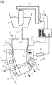
- a continuous caster has a mold 1.
- Liquid metal 3, for example liquid steel or liquid aluminum, is poured into the mold 1 via a dip tube 2.
- the inflow of the liquid metal 3 into the mold 1 is set by means of an inflow device 4.
- Is shown in Fig. 1 an embodiment of the inflow device 4 as a sealing plug.
- a position p of the inflow device 4 corresponds to a stroke position of the sealing plug.
- the inflow device 4 can be designed as a slide.
- the closed position p corresponds to the slide position.
- the liquid metal 3 located in the mold is cooled by means of cooling devices (not shown), so that it solidifies on the walls 1a of the mold 1 and thus forms a strand shell.
- a core 6 is still liquid. It only freezes later.
- the strand shell 5 and the core 6 together form a metal strand 7.
- the metal strand 7 is supported by means of a strand guide 8 and withdrawn from the mold 9.
- the strand guide 8 is arranged downstream of the mold 1. It has several roller segments 8a, which in turn have rollers 8b. Of the roller segments 8a and the rollers 8b are in Fig. 1 only a few shown. By means of the rollers 8b, the metal strand 7 is drawn out of the mold 1 at a withdrawal speed v.
- the liquid metal 3 forms a pour level 9 in the mold 1.
- the pour level 9 should be kept as constant as possible. Therefore - both in the prior art and in the present embodiment variant of the invention - the position p of the inflow device 4 is adjusted in order to adjust the inflow of the liquid metal 3 into the mold 1 accordingly.
- a measuring device 10 (known per se) is used to determine a height h of the meniscus 9 detected.
- the height h is fed to a control device 11 for the continuous caster.
- the control device 11 determines a manipulated variable S for the inflow device 4 according to a regulating method, which is explained in more detail below.
- the inflow device 4 is then controlled accordingly by the control device 11.
- the control device 11 outputs the manipulated variable S to an adjustment device 12 for the inflow device 4.
- roller spacings which correspond to the drawn strand thickness d, can be specifically adapted.
- at least one roller segment 8a has a fixed outer frame in the first segment, here approximately the roller segment 8a located directly below the mold 1 on the left.
- the opposite roller segment 8a, or the inner frame supporting it, can be pivoted about a pivot axis 23 which runs normal to the plane of the drawing.
- the pivot axis 23 can coincide with an axis of rotation of a roller 8b, here with the axis of rotation of the upper roller 8b, but could of course also be provided at another point.
- the top left roller segment 8a i.e. its outer frame, for example, could be fixed and the upper right roller segment 8a, i.e. its inner frame, for example, could be shifted parallel to and away from the left roller segment 8a normal to the strand guiding direction.
- each roller segment 8a has three rollers 8b on each side. But there could also be only two or more than three rollers 8b per roller segment 8a.
- Adjusting devices 24 are accordingly also provided in all segments 8a up to the solidification point D. The adjusting devices 24 can adjust the roller segments 8a in each case by pivoting or by parallel displacement, as already in Fig. 1 explained.
- the inner roller segment 8a of the first (top) segment is adjusted by pivoting about the pivot axis 23, the inner roller segment 8a of the second segment by parallel movement by means of two adjustment devices 24.
- the connection of the adjustment devices 24 to the control device 11 is not shown here.
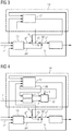
- the control device 11 implemented - see Fig. 3 - Among other things, a mold level regulator 13.
- the mold level regulator 13 is supplied with the height h of the mold level 9.
- a setpoint value h * for the height h of the meniscus 9 is also fed to the mold level controller 13.
- Further signals are also fed to the mold level controller 13.
- the further signals can be, for example, the width and the thickness of the cast metal strand 7 (or more generally the cross section of the metal strand 7), the withdrawal speed v (or its target value), 1 and others.
- the mold level controller 13 determines, based on the deviation of the height h of the mold level 9 from the setpoint h *, in particular a preliminary setpoint position p '* for the inflow device 4.
- the mold level controller 13 can use the other signals for its parameterization and / or to determine a precontrol signal pV .
- the control device 11 also implements a first observer 14.
- the first observer 14 is supplied with the height h of the mold level 9 and its target value h *, the further signals and a final target position p * for the inflow device 4.
- the first observer 14 determines a first compensation value k.
- the first compensation value k is applied to the preliminary target position p '* and the final target position p * is thus determined.
- the manipulated variable S with which the inflow device 4 is controlled is then determined.
- the control device 11 implements a subordinate position controller (not shown) for this purpose.
- first and second observers 14, 25 are not people, but rather functional blocks implemented in the control device 11.
- the difference between the preliminary target position p '* and the final target position p * corresponds to that of first observer 14 determined first compensation value k. Since the first compensation value k is determined by the first observer 14 and is therefore known to the first observer 14, the provisional target position p ′ * can also be supplied to the first observer 14 as an alternative to the final target position p *. Because due to the fact that the first compensation value k is known to the first observer 14, the first observer 14 can easily determine the final desired position p * from the preliminary desired position p ′ *.
- a tapping point 15, at which the (preliminary or final) target position p '*, p * is tapped, can thus, as required, be before or after a node 16 at which the first compensation value k is switched to the provisional target position p' *.
- the tapping point 15 should, however, lie in front of a node 16 'at which the pilot control signal pV is applied.
- the first observer 14 has a determination block 17.
- the height h of the mold level 9, the other signals and the final target position p * are fed to the determination block 17.
- the determination block 17 has a model of the continuous casting plant. Using the model, the determination block 17 uses the additional signals and the final target position p * to determine an expected (ie model-based calculated) height for the mold level 9. Using the expected height, the determination block 17 then determines an expected (ie model-based calculated) fluctuation value ⁇ h for the Height h of the meniscus 9, that is, the short-term fluctuation. For example, the determination block 17 can average the height h of the meniscus 9 and subtract the resulting mean value from the expected height. The determined fluctuation value ⁇ h thus reflects the expected fluctuation in the height h of the meniscus 9. Based on the fluctuation value ⁇ h, the determination block 17 then determines the first compensation value k.
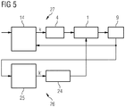
- the first observer 14 with the determination block 17 is shown again.
- the determination block 17 is as shown in FIG Fig. 4 however, only one of several components of the first observer 14.
- the first observer 14 additionally has a first analysis element 18.
- the fluctuation value ⁇ h is fed to the first analysis element 18.
- the first analysis element 18 uses this to determine the frequency components of the fluctuation value ⁇ h.
- a second analysis element 19 is preferably also present.
- An additional signal Z is fed to the second analysis element 19.
- the second analysis element 19 determines the frequency components of the additional signal Z from this.
- the additional signal Z can be a pull-out force F with which the metal strand 7 is pulled out of the mold 1 by the rollers 8b of the strand guide 8.
- the pull-out force F is directed parallel to the pull-off speed v.
- it can be the withdrawal speed v itself.
- a force signal F 'as additional signal Z with which (at least) one of the roller segments 8a of the strand guide 8 is applied.
- the direction to which the force signal F 'is related is orthogonal to the withdrawal speed v.
- the additional signal Z can be a local strand thickness d, which is measured by means of a measuring device 21 in the strand guide 8.
- the first analysis element 18 feeds the frequency components determined by it to a selection element 22. If available, this also applies in an analogous manner to the second analysis element 19.
- the selection element 22 determines the wavelengths at which the associated frequency component of the fluctuation value ⁇ h, possibly also the associated frequency component of the additional signal Z, is above a threshold value S1, S2.
- the determination block 17 filters the height h of the pouring level 9 and the final target position p * for the wavelengths ⁇ i selected by the selection element 22.
- the determination block 17 determines the first compensation value k only on the basis of the filtered height h of the meniscus 9 and the filtered final target position p *.
- the determination block 17 does not take into account the other frequency components of the height h of the meniscus 9 and the final desired position p * in the context of the determination of the first compensation value k.
- the selection member 22 can also be predetermined wave ranges. In this case, the predetermined wave ranges represent an additional selection criterion.
- wavelengths at which the associated frequency component of the fluctuation value ⁇ h, possibly also the associated frequency component of the additional signal Z is above the respective threshold value S1, S2 are only selected if they are also within one of the predetermined wavelength ranges. Otherwise, they are not selected even if the associated frequency component of the fluctuation value ⁇ h, possibly also the associated frequency component of the additional signal Z, is above the respective threshold value S1, S2.
- the second observer 25 has identical components as the first observer 14, analyzes frequencies of the strand pumping after the mold 1 and specifies a second compensation value k ′ for the adjustment device 24.
- a control circuit is shown which comprises a first and a second observer 14, 25.
- the first observer 14 specifies a first compensation value k for the inflow device 4 of the mold 1, as a result of which the mold level 9 in the mold 1 is regulated.
- the first observer 14 and the inflow device 4 of the mold 1 together represent a standard system for regulating the mold level 9 of the mold 1, which is used to compensate for frequencies in the first frequency range and thus represents a controller 27 for frequencies of the mold
- This single control method could be the second observer 25, but also another control or regulation method.
- the second observer or another sole control or regulation method would generally cover a larger frequency range than with two regulation methods. This frequency range could then cover, for example, the frequencies from 0 to 0.6 Hz, from 0 to 1 Hz, from 0 to 2 Hz, from 0 to 3 Hz, from 0 to 4 Hz or from 0 to 5 Hz.
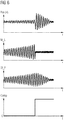
- Fig. 6 shows an example of suppressing cyclic oscillation.
- the time t is plotted along the horizontal axis.
- the position of the inflow device 4, labeled “Pos (4)” is shown in the first (top) illustration, and the height of the meniscus in the mold 1, labeled "M_L”, in the second illustration third illustration of the steel flow from the mold 1, labeled "St_Fl”.
- both the position of the inflow device 4 changes cyclically, as does the height of the meniscus and consequently the flow of steel from the mold.
- the cyclical fluctuations of the meniscus “M_L” are reduced.
- the mutual spacing of the rollers 8b in the uppermost segment would be changed cyclically in order to reduce the fluctuations in the pouring level.
Landscapes
- Engineering & Computer Science (AREA)
- Mechanical Engineering (AREA)
- Physics & Mathematics (AREA)
- Fluid Mechanics (AREA)
- General Physics & Mathematics (AREA)
- Continuous Casting (AREA)
Applications Claiming Priority (2)
| Application Number | Priority Date | Filing Date | Title |
|---|---|---|---|
| ATA51133/2016A AT519390B1 (de) | 2016-12-13 | 2016-12-13 | Verfahren und Vorrichtung zum Regeln einer Stranggießanlage |
| PCT/EP2017/081615 WO2018108652A1 (de) | 2016-12-13 | 2017-12-06 | Verfahren und vorrichtung zum regeln einer stranggiessanlage |
Publications (2)
| Publication Number | Publication Date |
|---|---|
| EP3554744A1 EP3554744A1 (de) | 2019-10-23 |
| EP3554744B1 true EP3554744B1 (de) | 2020-08-26 |
Family
ID=60574620
Family Applications (1)
| Application Number | Title | Priority Date | Filing Date |
|---|---|---|---|
| EP17808939.7A Active EP3554744B1 (de) | 2016-12-13 | 2017-12-06 | Verfahren und vorrichtung zum regeln einer stranggiessanlage |
Country Status (6)
| Country | Link |
|---|---|
| US (1) | US11110512B2 (ko) |
| EP (1) | EP3554744B1 (ko) |
| KR (1) | KR102386742B1 (ko) |
| CN (1) | CN110062672B (ko) |
| AT (1) | AT519390B1 (ko) |
| WO (1) | WO2018108652A1 (ko) |
Families Citing this family (4)
| Publication number | Priority date | Publication date | Assignee | Title |
|---|---|---|---|---|
| CN112808959B (zh) * | 2019-11-16 | 2022-07-15 | 上海梅山钢铁股份有限公司 | 一种提高成功率的结晶器高液位更换中间包方法 |
| CN113102707B (zh) * | 2021-03-29 | 2022-07-01 | 中国重型机械研究院股份公司 | 一种方坯连铸机的出坯系统及方法 |
| EP4140616A1 (de) | 2021-08-25 | 2023-03-01 | Primetals Technologies Austria GmbH | Verfahren und vorrichtung zum regeln einer stranggiessanlage |
| CN114918393B (zh) * | 2022-06-09 | 2024-07-19 | 吉林建龙钢铁有限责任公司 | 一种控制中、低碳钢结晶器液位周期性波动的方法 |
Family Cites Families (15)
| Publication number | Priority date | Publication date | Assignee | Title |
|---|---|---|---|---|
| US4597048A (en) * | 1983-09-07 | 1986-06-24 | United States Steel Corporation | Digital flow regulation of liquid-level control for a continuous casting mold |
| DE19745547A1 (de) | 1996-11-08 | 1999-06-02 | Mannesmann Ag | Verfahren und Anlage zum Stranggießen von Dünnbrammen |
| JP3318742B2 (ja) * | 1999-01-14 | 2002-08-26 | 住友重機械工業株式会社 | 連続鋳造設備のモールド湯面制御装置 |
| DE19951262C1 (de) * | 1999-10-25 | 2001-04-05 | Sms Demag Ag | Strangführungsgerüst einer Stranggießanlage, insbesondere für Dünnbrammen aus Stahl |
| AT410409B (de) | 2001-04-03 | 2003-04-25 | Voest Alpine Ind Anlagen | Verfahren zum stranggiessen von metallschmelzen sowie stranggiessanlage zur durchführung des verfahrens |
| DE102004002783A1 (de) * | 2004-01-20 | 2005-08-04 | Sms Demag Ag | Verfahren und Einrichtung zum Bestimmen der Lage der Sumpfspitze im Gießstrang beim Stranggießen von flüssigen Metallen, insbesondere von flüssigen Stahlwerkstoffen |
| AT502525B1 (de) * | 2005-10-12 | 2008-05-15 | Voest Alpine Ind Anlagen | Verfahren zum stranggiessen einer metallschmelze |
| DE102006018757A1 (de) * | 2006-04-22 | 2007-10-25 | Sms Demag Ag | Verfahren für die Bestimmung der Rollenabständen von Stützrollen und Strangführungsgerüst einer Stranggießanlage zum Gießen von flüssigen Metallen, insbesondere von flüssigen Stahlwerkstoffen |
| DE102008025548A1 (de) * | 2008-05-28 | 2009-12-03 | Sms Siemag Aktiengesellschaft | Strangführung, insbesondere für eine Stahlbrammen-Stranggießanlage |
| EP2272605A1 (de) | 2009-06-24 | 2011-01-12 | Siemens AG | Regelverfahren für den Gießspiegel einer Stranggießkokille |
| CN101920316B (zh) | 2010-08-03 | 2015-08-19 | 中国重型机械研究院有限公司 | 一种解决结晶器液面波动的连铸机改造方法 |
| KR101360552B1 (ko) | 2011-12-19 | 2014-02-11 | 주식회사 포스코 | 연주 설비 |
| AT514734A1 (de) * | 2013-05-03 | 2015-03-15 | Tbr Casting Technologies Gmbh | Verfahren und Vorrichtung zur Regelung des Flüssigmetallspiegels in einer Stranggießkokille |
| CN104275448A (zh) | 2014-10-27 | 2015-01-14 | 大连理工大学 | 一种包晶钢连铸板坯鼓肚在线检测方法 |
| AT518461B1 (de) | 2016-04-11 | 2019-12-15 | Primetals Technologies Austria GmbH | Gießspiegelregelung mit Störgrößenkompensation |
-
2016
- 2016-12-13 AT ATA51133/2016A patent/AT519390B1/de active
-
2017
- 2017-12-06 WO PCT/EP2017/081615 patent/WO2018108652A1/de active Search and Examination
- 2017-12-06 KR KR1020197016831A patent/KR102386742B1/ko active IP Right Grant
- 2017-12-06 EP EP17808939.7A patent/EP3554744B1/de active Active
- 2017-12-06 CN CN201780077251.1A patent/CN110062672B/zh active Active
- 2017-12-06 US US16/466,313 patent/US11110512B2/en active Active
Non-Patent Citations (1)
| Title |
|---|
| None * |
Also Published As
| Publication number | Publication date |
|---|---|
| AT519390A1 (de) | 2018-06-15 |
| KR102386742B1 (ko) | 2022-04-13 |
| EP3554744A1 (de) | 2019-10-23 |
| AT519390B1 (de) | 2020-09-15 |
| US20190308238A1 (en) | 2019-10-10 |
| WO2018108652A1 (de) | 2018-06-21 |
| CN110062672A (zh) | 2019-07-26 |
| US11110512B2 (en) | 2021-09-07 |
| KR20190094368A (ko) | 2019-08-13 |
| CN110062672B (zh) | 2022-04-05 |
Similar Documents
| Publication | Publication Date | Title |
|---|---|---|
| EP3554744B1 (de) | Verfahren und vorrichtung zum regeln einer stranggiessanlage | |
| EP3184202B1 (de) | Verfahren zum stranggiessen eines metallstranges | |
| EP3515634B1 (de) | Regelung der schmalseitenkonizität einer stranggusskokille : verfahren und vorrichtung | |
| AT410767B (de) | Verfahren und vorrichtung zur kontinuierlichen herstellung eines gewalzten metallbandes aus einermetallschmelze | |
| AT502525B1 (de) | Verfahren zum stranggiessen einer metallschmelze | |
| EP1536900B2 (de) | Verfahren zum Starten eines Giessvorganges | |
| DE19817034A1 (de) | Verfahren und Vorrichtung zum Stranggießen von dünnen Metallbändern | |
| EP2906369B1 (de) | Breitenbeeinflussung eines bandförmigen walzguts | |
| EP3733323A1 (de) | Verfahren und stranggiessanlage zum giessen eines giessstrangs | |
| EP1731243A2 (de) | Verfahren und Vorrichtung zum Stranggiessen von flüssigen Metallen, insbesondere von flüssigen Stahlwerkstoffen, mit einer Strangführung aus Stützrollensegmenten | |
| AT518461B1 (de) | Gießspiegelregelung mit Störgrößenkompensation | |
| EP3173166B1 (de) | Verfahren und vorrichtung zum einstellen der breite eines stranggegossenen metallstrangs | |
| WO2023025669A1 (de) | Verfahren und vorrichtung zum regeln einer stranggiessanlage | |
| DE10122118A1 (de) | Verfahren und Vorrichtung zum Stranggiessen von Blöcken, Brammen und Dünnbrammen | |
| EP1827735A1 (de) | Verfahren und vorrichtung zum bandgiessen von metallen | |
| AT525046B1 (de) | Kompakter, energiesparender und hochdynamischer Hydraulikantrieb für die Oszillation einer Kokille einer Stranggießmaschine | |
| AT410409B (de) | Verfahren zum stranggiessen von metallschmelzen sowie stranggiessanlage zur durchführung des verfahrens | |
| EP3706933B1 (de) | Strangführungssegment und stranggiessanlage | |
| DE19633738C2 (de) | Verfahren und Einrichtung zum Gießen eines Stranges aus flüssigem Metall | |
| EP3944910A1 (de) | Verfahren zur herstellung eines giessstrangs in einer stranggiessanlage | |
| EP1467828A2 (de) | Giessvorrichtung |
Legal Events
| Date | Code | Title | Description |
|---|---|---|---|
| STAA | Information on the status of an ep patent application or granted ep patent |
Free format text: STATUS: UNKNOWN |
|
| STAA | Information on the status of an ep patent application or granted ep patent |
Free format text: STATUS: THE INTERNATIONAL PUBLICATION HAS BEEN MADE |
|
| PUAI | Public reference made under article 153(3) epc to a published international application that has entered the european phase |
Free format text: ORIGINAL CODE: 0009012 |
|
| STAA | Information on the status of an ep patent application or granted ep patent |
Free format text: STATUS: REQUEST FOR EXAMINATION WAS MADE |
|
| 17P | Request for examination filed |
Effective date: 20190715 |
|
| AK | Designated contracting states |
Kind code of ref document: A1 Designated state(s): AL AT BE BG CH CY CZ DE DK EE ES FI FR GB GR HR HU IE IS IT LI LT LU LV MC MK MT NL NO PL PT RO RS SE SI SK SM TR |
|
| AX | Request for extension of the european patent |
Extension state: BA ME |
|
| DAV | Request for validation of the european patent (deleted) | ||
| DAX | Request for extension of the european patent (deleted) | ||
| REG | Reference to a national code |
Ref country code: DE Ref legal event code: R079 Ref document number: 502017006975 Country of ref document: DE Free format text: PREVIOUS MAIN CLASS: B22D0011200000 Ipc: B22D0011180000 |
|
| GRAP | Despatch of communication of intention to grant a patent |
Free format text: ORIGINAL CODE: EPIDOSNIGR1 |
|
| STAA | Information on the status of an ep patent application or granted ep patent |
Free format text: STATUS: GRANT OF PATENT IS INTENDED |
|
| RIC1 | Information provided on ipc code assigned before grant |
Ipc: B22D 11/18 20060101AFI20200408BHEP Ipc: B22D 11/20 20060101ALI20200408BHEP |
|
| INTG | Intention to grant announced |
Effective date: 20200430 |
|
| GRAS | Grant fee paid |
Free format text: ORIGINAL CODE: EPIDOSNIGR3 |
|
| GRAA | (expected) grant |
Free format text: ORIGINAL CODE: 0009210 |
|
| STAA | Information on the status of an ep patent application or granted ep patent |
Free format text: STATUS: THE PATENT HAS BEEN GRANTED |
|
| AK | Designated contracting states |
Kind code of ref document: B1 Designated state(s): AL AT BE BG CH CY CZ DE DK EE ES FI FR GB GR HR HU IE IS IT LI LT LU LV MC MK MT NL NO PL PT RO RS SE SI SK SM TR |
|
| REG | Reference to a national code |
Ref country code: GB Ref legal event code: FG4D Free format text: NOT ENGLISH |
|
| REG | Reference to a national code |
Ref country code: CH Ref legal event code: EP |
|
| REG | Reference to a national code |
Ref country code: DE Ref legal event code: R096 Ref document number: 502017006975 Country of ref document: DE |
|
| REG | Reference to a national code |
Ref country code: AT Ref legal event code: REF Ref document number: 1305893 Country of ref document: AT Kind code of ref document: T Effective date: 20200915 |
|
| REG | Reference to a national code |
Ref country code: IE Ref legal event code: FG4D Free format text: LANGUAGE OF EP DOCUMENT: GERMAN |
|
| REG | Reference to a national code |
Ref country code: LT Ref legal event code: MG4D |
|
| PG25 | Lapsed in a contracting state [announced via postgrant information from national office to epo] |
Ref country code: SE Free format text: LAPSE BECAUSE OF FAILURE TO SUBMIT A TRANSLATION OF THE DESCRIPTION OR TO PAY THE FEE WITHIN THE PRESCRIBED TIME-LIMIT Effective date: 20200826 Ref country code: PT Free format text: LAPSE BECAUSE OF FAILURE TO SUBMIT A TRANSLATION OF THE DESCRIPTION OR TO PAY THE FEE WITHIN THE PRESCRIBED TIME-LIMIT Effective date: 20201228 Ref country code: FI Free format text: LAPSE BECAUSE OF FAILURE TO SUBMIT A TRANSLATION OF THE DESCRIPTION OR TO PAY THE FEE WITHIN THE PRESCRIBED TIME-LIMIT Effective date: 20200826 Ref country code: BG Free format text: LAPSE BECAUSE OF FAILURE TO SUBMIT A TRANSLATION OF THE DESCRIPTION OR TO PAY THE FEE WITHIN THE PRESCRIBED TIME-LIMIT Effective date: 20201126 Ref country code: NO Free format text: LAPSE BECAUSE OF FAILURE TO SUBMIT A TRANSLATION OF THE DESCRIPTION OR TO PAY THE FEE WITHIN THE PRESCRIBED TIME-LIMIT Effective date: 20201126 Ref country code: GR Free format text: LAPSE BECAUSE OF FAILURE TO SUBMIT A TRANSLATION OF THE DESCRIPTION OR TO PAY THE FEE WITHIN THE PRESCRIBED TIME-LIMIT Effective date: 20201127 Ref country code: LT Free format text: LAPSE BECAUSE OF FAILURE TO SUBMIT A TRANSLATION OF THE DESCRIPTION OR TO PAY THE FEE WITHIN THE PRESCRIBED TIME-LIMIT Effective date: 20200826 Ref country code: HR Free format text: LAPSE BECAUSE OF FAILURE TO SUBMIT A TRANSLATION OF THE DESCRIPTION OR TO PAY THE FEE WITHIN THE PRESCRIBED TIME-LIMIT Effective date: 20200826 |
|
| REG | Reference to a national code |
Ref country code: NL Ref legal event code: MP Effective date: 20200826 |
|
| PG25 | Lapsed in a contracting state [announced via postgrant information from national office to epo] |
Ref country code: IS Free format text: LAPSE BECAUSE OF FAILURE TO SUBMIT A TRANSLATION OF THE DESCRIPTION OR TO PAY THE FEE WITHIN THE PRESCRIBED TIME-LIMIT Effective date: 20201226 Ref country code: LV Free format text: LAPSE BECAUSE OF FAILURE TO SUBMIT A TRANSLATION OF THE DESCRIPTION OR TO PAY THE FEE WITHIN THE PRESCRIBED TIME-LIMIT Effective date: 20200826 Ref country code: PL Free format text: LAPSE BECAUSE OF FAILURE TO SUBMIT A TRANSLATION OF THE DESCRIPTION OR TO PAY THE FEE WITHIN THE PRESCRIBED TIME-LIMIT Effective date: 20200826 Ref country code: RS Free format text: LAPSE BECAUSE OF FAILURE TO SUBMIT A TRANSLATION OF THE DESCRIPTION OR TO PAY THE FEE WITHIN THE PRESCRIBED TIME-LIMIT Effective date: 20200826 Ref country code: NL Free format text: LAPSE BECAUSE OF FAILURE TO SUBMIT A TRANSLATION OF THE DESCRIPTION OR TO PAY THE FEE WITHIN THE PRESCRIBED TIME-LIMIT Effective date: 20200826 |
|
| PG25 | Lapsed in a contracting state [announced via postgrant information from national office to epo] |
Ref country code: DK Free format text: LAPSE BECAUSE OF FAILURE TO SUBMIT A TRANSLATION OF THE DESCRIPTION OR TO PAY THE FEE WITHIN THE PRESCRIBED TIME-LIMIT Effective date: 20200826 Ref country code: CZ Free format text: LAPSE BECAUSE OF FAILURE TO SUBMIT A TRANSLATION OF THE DESCRIPTION OR TO PAY THE FEE WITHIN THE PRESCRIBED TIME-LIMIT Effective date: 20200826 Ref country code: RO Free format text: LAPSE BECAUSE OF FAILURE TO SUBMIT A TRANSLATION OF THE DESCRIPTION OR TO PAY THE FEE WITHIN THE PRESCRIBED TIME-LIMIT Effective date: 20200826 Ref country code: EE Free format text: LAPSE BECAUSE OF FAILURE TO SUBMIT A TRANSLATION OF THE DESCRIPTION OR TO PAY THE FEE WITHIN THE PRESCRIBED TIME-LIMIT Effective date: 20200826 Ref country code: SM Free format text: LAPSE BECAUSE OF FAILURE TO SUBMIT A TRANSLATION OF THE DESCRIPTION OR TO PAY THE FEE WITHIN THE PRESCRIBED TIME-LIMIT Effective date: 20200826 |
|
| REG | Reference to a national code |
Ref country code: DE Ref legal event code: R097 Ref document number: 502017006975 Country of ref document: DE |
|
| PG25 | Lapsed in a contracting state [announced via postgrant information from national office to epo] |
Ref country code: ES Free format text: LAPSE BECAUSE OF FAILURE TO SUBMIT A TRANSLATION OF THE DESCRIPTION OR TO PAY THE FEE WITHIN THE PRESCRIBED TIME-LIMIT Effective date: 20200826 Ref country code: AL Free format text: LAPSE BECAUSE OF FAILURE TO SUBMIT A TRANSLATION OF THE DESCRIPTION OR TO PAY THE FEE WITHIN THE PRESCRIBED TIME-LIMIT Effective date: 20200826 |
|
| PG25 | Lapsed in a contracting state [announced via postgrant information from national office to epo] |
Ref country code: SK Free format text: LAPSE BECAUSE OF FAILURE TO SUBMIT A TRANSLATION OF THE DESCRIPTION OR TO PAY THE FEE WITHIN THE PRESCRIBED TIME-LIMIT Effective date: 20200826 |
|
| PLBE | No opposition filed within time limit |
Free format text: ORIGINAL CODE: 0009261 |
|
| STAA | Information on the status of an ep patent application or granted ep patent |
Free format text: STATUS: NO OPPOSITION FILED WITHIN TIME LIMIT |
|
| REG | Reference to a national code |
Ref country code: CH Ref legal event code: PL |
|
| 26N | No opposition filed |
Effective date: 20210527 |
|
| PG25 | Lapsed in a contracting state [announced via postgrant information from national office to epo] |
Ref country code: SI Free format text: LAPSE BECAUSE OF FAILURE TO SUBMIT A TRANSLATION OF THE DESCRIPTION OR TO PAY THE FEE WITHIN THE PRESCRIBED TIME-LIMIT Effective date: 20200826 Ref country code: MC Free format text: LAPSE BECAUSE OF FAILURE TO SUBMIT A TRANSLATION OF THE DESCRIPTION OR TO PAY THE FEE WITHIN THE PRESCRIBED TIME-LIMIT Effective date: 20200826 |
|
| REG | Reference to a national code |
Ref country code: BE Ref legal event code: MM Effective date: 20201231 |
|
| PG25 | Lapsed in a contracting state [announced via postgrant information from national office to epo] |
Ref country code: LU Free format text: LAPSE BECAUSE OF NON-PAYMENT OF DUE FEES Effective date: 20201206 Ref country code: IE Free format text: LAPSE BECAUSE OF NON-PAYMENT OF DUE FEES Effective date: 20201206 Ref country code: FR Free format text: LAPSE BECAUSE OF NON-PAYMENT OF DUE FEES Effective date: 20201231 |
|
| PG25 | Lapsed in a contracting state [announced via postgrant information from national office to epo] |
Ref country code: CH Free format text: LAPSE BECAUSE OF NON-PAYMENT OF DUE FEES Effective date: 20201231 Ref country code: LI Free format text: LAPSE BECAUSE OF NON-PAYMENT OF DUE FEES Effective date: 20201231 |
|
| PG25 | Lapsed in a contracting state [announced via postgrant information from national office to epo] |
Ref country code: TR Free format text: LAPSE BECAUSE OF FAILURE TO SUBMIT A TRANSLATION OF THE DESCRIPTION OR TO PAY THE FEE WITHIN THE PRESCRIBED TIME-LIMIT Effective date: 20200826 Ref country code: MT Free format text: LAPSE BECAUSE OF FAILURE TO SUBMIT A TRANSLATION OF THE DESCRIPTION OR TO PAY THE FEE WITHIN THE PRESCRIBED TIME-LIMIT Effective date: 20200826 Ref country code: CY Free format text: LAPSE BECAUSE OF FAILURE TO SUBMIT A TRANSLATION OF THE DESCRIPTION OR TO PAY THE FEE WITHIN THE PRESCRIBED TIME-LIMIT Effective date: 20200826 |
|
| PG25 | Lapsed in a contracting state [announced via postgrant information from national office to epo] |
Ref country code: MK Free format text: LAPSE BECAUSE OF FAILURE TO SUBMIT A TRANSLATION OF THE DESCRIPTION OR TO PAY THE FEE WITHIN THE PRESCRIBED TIME-LIMIT Effective date: 20200826 |
|
| PG25 | Lapsed in a contracting state [announced via postgrant information from national office to epo] |
Ref country code: BE Free format text: LAPSE BECAUSE OF NON-PAYMENT OF DUE FEES Effective date: 20201231 |
|
| GBPC | Gb: european patent ceased through non-payment of renewal fee |
Effective date: 20211206 |
|
| PG25 | Lapsed in a contracting state [announced via postgrant information from national office to epo] |
Ref country code: GB Free format text: LAPSE BECAUSE OF NON-PAYMENT OF DUE FEES Effective date: 20211206 |
|
| PGFP | Annual fee paid to national office [announced via postgrant information from national office to epo] |
Ref country code: IT Payment date: 20231228 Year of fee payment: 7 Ref country code: DE Payment date: 20231214 Year of fee payment: 7 |
|
| REG | Reference to a national code |
Ref country code: AT Ref legal event code: MM01 Ref document number: 1305893 Country of ref document: AT Kind code of ref document: T Effective date: 20221206 |
|
| PG25 | Lapsed in a contracting state [announced via postgrant information from national office to epo] |
Ref country code: AT Free format text: LAPSE BECAUSE OF NON-PAYMENT OF DUE FEES Effective date: 20221206 |
|
| PG25 | Lapsed in a contracting state [announced via postgrant information from national office to epo] |
Ref country code: AT Free format text: LAPSE BECAUSE OF NON-PAYMENT OF DUE FEES Effective date: 20221206 |