EP3554577B1 - Système de traitement extracorporel du sang et dispositif de traitement - Google Patents
Système de traitement extracorporel du sang et dispositif de traitement Download PDFInfo
- Publication number
- EP3554577B1 EP3554577B1 EP17828682.9A EP17828682A EP3554577B1 EP 3554577 B1 EP3554577 B1 EP 3554577B1 EP 17828682 A EP17828682 A EP 17828682A EP 3554577 B1 EP3554577 B1 EP 3554577B1
- Authority
- EP
- European Patent Office
- Prior art keywords
- blood
- treatment
- treated
- bloodstream
- dialysis
- Prior art date
- Legal status (The legal status is an assumption and is not a legal conclusion. Google has not performed a legal analysis and makes no representation as to the accuracy of the status listed.)
- Active
Links
Images

Classifications
-
- A—HUMAN NECESSITIES
- A61—MEDICAL OR VETERINARY SCIENCE; HYGIENE
- A61M—DEVICES FOR INTRODUCING MEDIA INTO, OR ONTO, THE BODY; DEVICES FOR TRANSDUCING BODY MEDIA OR FOR TAKING MEDIA FROM THE BODY; DEVICES FOR PRODUCING OR ENDING SLEEP OR STUPOR
- A61M1/00—Suction or pumping devices for medical purposes; Devices for carrying-off, for treatment of, or for carrying-over, body-liquids; Drainage systems
- A61M1/34—Filtering material out of the blood by passing it through a membrane, i.e. hemofiltration or diafiltration
- A61M1/3413—Diafiltration
-
- A—HUMAN NECESSITIES
- A61—MEDICAL OR VETERINARY SCIENCE; HYGIENE
- A61M—DEVICES FOR INTRODUCING MEDIA INTO, OR ONTO, THE BODY; DEVICES FOR TRANSDUCING BODY MEDIA OR FOR TAKING MEDIA FROM THE BODY; DEVICES FOR PRODUCING OR ENDING SLEEP OR STUPOR
- A61M1/00—Suction or pumping devices for medical purposes; Devices for carrying-off, for treatment of, or for carrying-over, body-liquids; Drainage systems
- A61M1/14—Dialysis systems; Artificial kidneys; Blood oxygenators ; Reciprocating systems for treatment of body fluids, e.g. single needle systems for hemofiltration or pheresis
- A61M1/16—Dialysis systems; Artificial kidneys; Blood oxygenators ; Reciprocating systems for treatment of body fluids, e.g. single needle systems for hemofiltration or pheresis with membranes
- A61M1/1698—Blood oxygenators with or without heat-exchangers
-
- A—HUMAN NECESSITIES
- A61—MEDICAL OR VETERINARY SCIENCE; HYGIENE
- A61M—DEVICES FOR INTRODUCING MEDIA INTO, OR ONTO, THE BODY; DEVICES FOR TRANSDUCING BODY MEDIA OR FOR TAKING MEDIA FROM THE BODY; DEVICES FOR PRODUCING OR ENDING SLEEP OR STUPOR
- A61M1/00—Suction or pumping devices for medical purposes; Devices for carrying-off, for treatment of, or for carrying-over, body-liquids; Drainage systems
- A61M1/14—Dialysis systems; Artificial kidneys; Blood oxygenators ; Reciprocating systems for treatment of body fluids, e.g. single needle systems for hemofiltration or pheresis
- A61M1/16—Dialysis systems; Artificial kidneys; Blood oxygenators ; Reciprocating systems for treatment of body fluids, e.g. single needle systems for hemofiltration or pheresis with membranes
- A61M1/26—Dialysis systems; Artificial kidneys; Blood oxygenators ; Reciprocating systems for treatment of body fluids, e.g. single needle systems for hemofiltration or pheresis with membranes and internal elements which are moving
- A61M1/267—Dialysis systems; Artificial kidneys; Blood oxygenators ; Reciprocating systems for treatment of body fluids, e.g. single needle systems for hemofiltration or pheresis with membranes and internal elements which are moving used for pumping
-
- A—HUMAN NECESSITIES
- A61—MEDICAL OR VETERINARY SCIENCE; HYGIENE
- A61M—DEVICES FOR INTRODUCING MEDIA INTO, OR ONTO, THE BODY; DEVICES FOR TRANSDUCING BODY MEDIA OR FOR TAKING MEDIA FROM THE BODY; DEVICES FOR PRODUCING OR ENDING SLEEP OR STUPOR
- A61M1/00—Suction or pumping devices for medical purposes; Devices for carrying-off, for treatment of, or for carrying-over, body-liquids; Drainage systems
- A61M1/34—Filtering material out of the blood by passing it through a membrane, i.e. hemofiltration or diafiltration
- A61M1/342—Adding solutions to the blood, e.g. substitution solutions
- A61M1/3424—Substitution fluid path
- A61M1/3431—Substitution fluid path upstream of the filter
- A61M1/3434—Substitution fluid path upstream of the filter with pre-dilution and post-dilution
-
- A—HUMAN NECESSITIES
- A61—MEDICAL OR VETERINARY SCIENCE; HYGIENE
- A61M—DEVICES FOR INTRODUCING MEDIA INTO, OR ONTO, THE BODY; DEVICES FOR TRANSDUCING BODY MEDIA OR FOR TAKING MEDIA FROM THE BODY; DEVICES FOR PRODUCING OR ENDING SLEEP OR STUPOR
- A61M1/00—Suction or pumping devices for medical purposes; Devices for carrying-off, for treatment of, or for carrying-over, body-liquids; Drainage systems
- A61M1/34—Filtering material out of the blood by passing it through a membrane, i.e. hemofiltration or diafiltration
- A61M1/342—Adding solutions to the blood, e.g. substitution solutions
- A61M1/3441—Substitution rate control as a function of the ultrafiltration rate
-
- A—HUMAN NECESSITIES
- A61—MEDICAL OR VETERINARY SCIENCE; HYGIENE
- A61M—DEVICES FOR INTRODUCING MEDIA INTO, OR ONTO, THE BODY; DEVICES FOR TRANSDUCING BODY MEDIA OR FOR TAKING MEDIA FROM THE BODY; DEVICES FOR PRODUCING OR ENDING SLEEP OR STUPOR
- A61M1/00—Suction or pumping devices for medical purposes; Devices for carrying-off, for treatment of, or for carrying-over, body-liquids; Drainage systems
- A61M1/34—Filtering material out of the blood by passing it through a membrane, i.e. hemofiltration or diafiltration
- A61M1/3496—Plasmapheresis; Leucopheresis; Lymphopheresis
-
- A—HUMAN NECESSITIES
- A61—MEDICAL OR VETERINARY SCIENCE; HYGIENE
- A61M—DEVICES FOR INTRODUCING MEDIA INTO, OR ONTO, THE BODY; DEVICES FOR TRANSDUCING BODY MEDIA OR FOR TAKING MEDIA FROM THE BODY; DEVICES FOR PRODUCING OR ENDING SLEEP OR STUPOR
- A61M1/00—Suction or pumping devices for medical purposes; Devices for carrying-off, for treatment of, or for carrying-over, body-liquids; Drainage systems
- A61M1/36—Other treatment of blood in a by-pass of the natural circulatory system, e.g. temperature adaptation, irradiation ; Extra-corporeal blood circuits
- A61M1/3601—Extra-corporeal circuits in which the blood fluid passes more than once through the treatment unit
- A61M1/3603—Extra-corporeal circuits in which the blood fluid passes more than once through the treatment unit in the same direction
-
- A—HUMAN NECESSITIES
- A61—MEDICAL OR VETERINARY SCIENCE; HYGIENE
- A61M—DEVICES FOR INTRODUCING MEDIA INTO, OR ONTO, THE BODY; DEVICES FOR TRANSDUCING BODY MEDIA OR FOR TAKING MEDIA FROM THE BODY; DEVICES FOR PRODUCING OR ENDING SLEEP OR STUPOR
- A61M1/00—Suction or pumping devices for medical purposes; Devices for carrying-off, for treatment of, or for carrying-over, body-liquids; Drainage systems
- A61M1/36—Other treatment of blood in a by-pass of the natural circulatory system, e.g. temperature adaptation, irradiation ; Extra-corporeal blood circuits
- A61M1/3621—Extra-corporeal blood circuits
- A61M1/3622—Extra-corporeal blood circuits with a cassette forming partially or totally the blood circuit
- A61M1/36225—Extra-corporeal blood circuits with a cassette forming partially or totally the blood circuit with blood pumping means or components thereof
-
- A—HUMAN NECESSITIES
- A61—MEDICAL OR VETERINARY SCIENCE; HYGIENE
- A61M—DEVICES FOR INTRODUCING MEDIA INTO, OR ONTO, THE BODY; DEVICES FOR TRANSDUCING BODY MEDIA OR FOR TAKING MEDIA FROM THE BODY; DEVICES FOR PRODUCING OR ENDING SLEEP OR STUPOR
- A61M1/00—Suction or pumping devices for medical purposes; Devices for carrying-off, for treatment of, or for carrying-over, body-liquids; Drainage systems
- A61M1/36—Other treatment of blood in a by-pass of the natural circulatory system, e.g. temperature adaptation, irradiation ; Extra-corporeal blood circuits
- A61M1/3621—Extra-corporeal blood circuits
- A61M1/3626—Gas bubble detectors
-
- A—HUMAN NECESSITIES
- A61—MEDICAL OR VETERINARY SCIENCE; HYGIENE
- A61M—DEVICES FOR INTRODUCING MEDIA INTO, OR ONTO, THE BODY; DEVICES FOR TRANSDUCING BODY MEDIA OR FOR TAKING MEDIA FROM THE BODY; DEVICES FOR PRODUCING OR ENDING SLEEP OR STUPOR
- A61M1/00—Suction or pumping devices for medical purposes; Devices for carrying-off, for treatment of, or for carrying-over, body-liquids; Drainage systems
- A61M1/36—Other treatment of blood in a by-pass of the natural circulatory system, e.g. temperature adaptation, irradiation ; Extra-corporeal blood circuits
- A61M1/3621—Extra-corporeal blood circuits
- A61M1/3639—Blood pressure control, pressure transducers specially adapted therefor
-
- A—HUMAN NECESSITIES
- A61—MEDICAL OR VETERINARY SCIENCE; HYGIENE
- A61M—DEVICES FOR INTRODUCING MEDIA INTO, OR ONTO, THE BODY; DEVICES FOR TRANSDUCING BODY MEDIA OR FOR TAKING MEDIA FROM THE BODY; DEVICES FOR PRODUCING OR ENDING SLEEP OR STUPOR
- A61M1/00—Suction or pumping devices for medical purposes; Devices for carrying-off, for treatment of, or for carrying-over, body-liquids; Drainage systems
- A61M1/36—Other treatment of blood in a by-pass of the natural circulatory system, e.g. temperature adaptation, irradiation ; Extra-corporeal blood circuits
- A61M1/3621—Extra-corporeal blood circuits
- A61M1/3653—Interfaces between patient blood circulation and extra-corporal blood circuit
-
- A—HUMAN NECESSITIES
- A61—MEDICAL OR VETERINARY SCIENCE; HYGIENE
- A61M—DEVICES FOR INTRODUCING MEDIA INTO, OR ONTO, THE BODY; DEVICES FOR TRANSDUCING BODY MEDIA OR FOR TAKING MEDIA FROM THE BODY; DEVICES FOR PRODUCING OR ENDING SLEEP OR STUPOR
- A61M1/00—Suction or pumping devices for medical purposes; Devices for carrying-off, for treatment of, or for carrying-over, body-liquids; Drainage systems
- A61M1/36—Other treatment of blood in a by-pass of the natural circulatory system, e.g. temperature adaptation, irradiation ; Extra-corporeal blood circuits
- A61M1/3621—Extra-corporeal blood circuits
- A61M1/3666—Cardiac or cardiopulmonary bypass, e.g. heart-lung machines
-
- A—HUMAN NECESSITIES
- A61—MEDICAL OR VETERINARY SCIENCE; HYGIENE
- A61M—DEVICES FOR INTRODUCING MEDIA INTO, OR ONTO, THE BODY; DEVICES FOR TRANSDUCING BODY MEDIA OR FOR TAKING MEDIA FROM THE BODY; DEVICES FOR PRODUCING OR ENDING SLEEP OR STUPOR
- A61M1/00—Suction or pumping devices for medical purposes; Devices for carrying-off, for treatment of, or for carrying-over, body-liquids; Drainage systems
- A61M1/36—Other treatment of blood in a by-pass of the natural circulatory system, e.g. temperature adaptation, irradiation ; Extra-corporeal blood circuits
- A61M1/3679—Other treatment of blood in a by-pass of the natural circulatory system, e.g. temperature adaptation, irradiation ; Extra-corporeal blood circuits by absorption
-
- A—HUMAN NECESSITIES
- A61—MEDICAL OR VETERINARY SCIENCE; HYGIENE
- A61M—DEVICES FOR INTRODUCING MEDIA INTO, OR ONTO, THE BODY; DEVICES FOR TRANSDUCING BODY MEDIA OR FOR TAKING MEDIA FROM THE BODY; DEVICES FOR PRODUCING OR ENDING SLEEP OR STUPOR
- A61M2202/00—Special media to be introduced, removed or treated
- A61M2202/20—Pathogenic agents
- A61M2202/203—Bacteria
-
- A—HUMAN NECESSITIES
- A61—MEDICAL OR VETERINARY SCIENCE; HYGIENE
- A61M—DEVICES FOR INTRODUCING MEDIA INTO, OR ONTO, THE BODY; DEVICES FOR TRANSDUCING BODY MEDIA OR FOR TAKING MEDIA FROM THE BODY; DEVICES FOR PRODUCING OR ENDING SLEEP OR STUPOR
- A61M2202/00—Special media to be introduced, removed or treated
- A61M2202/20—Pathogenic agents
- A61M2202/206—Viruses
-
- A—HUMAN NECESSITIES
- A61—MEDICAL OR VETERINARY SCIENCE; HYGIENE
- A61M—DEVICES FOR INTRODUCING MEDIA INTO, OR ONTO, THE BODY; DEVICES FOR TRANSDUCING BODY MEDIA OR FOR TAKING MEDIA FROM THE BODY; DEVICES FOR PRODUCING OR ENDING SLEEP OR STUPOR
- A61M2205/00—General characteristics of the apparatus
- A61M2205/02—General characteristics of the apparatus characterised by a particular materials
- A61M2205/0238—General characteristics of the apparatus characterised by a particular materials the material being a coating or protective layer
-
- A—HUMAN NECESSITIES
- A61—MEDICAL OR VETERINARY SCIENCE; HYGIENE
- A61M—DEVICES FOR INTRODUCING MEDIA INTO, OR ONTO, THE BODY; DEVICES FOR TRANSDUCING BODY MEDIA OR FOR TAKING MEDIA FROM THE BODY; DEVICES FOR PRODUCING OR ENDING SLEEP OR STUPOR
- A61M2205/00—General characteristics of the apparatus
- A61M2205/12—General characteristics of the apparatus with interchangeable cassettes forming partially or totally the fluid circuit
-
- A—HUMAN NECESSITIES
- A61—MEDICAL OR VETERINARY SCIENCE; HYGIENE
- A61M—DEVICES FOR INTRODUCING MEDIA INTO, OR ONTO, THE BODY; DEVICES FOR TRANSDUCING BODY MEDIA OR FOR TAKING MEDIA FROM THE BODY; DEVICES FOR PRODUCING OR ENDING SLEEP OR STUPOR
- A61M2205/00—General characteristics of the apparatus
- A61M2205/33—Controlling, regulating or measuring
- A61M2205/3331—Pressure; Flow
- A61M2205/3334—Measuring or controlling the flow rate
-
- A—HUMAN NECESSITIES
- A61—MEDICAL OR VETERINARY SCIENCE; HYGIENE
- A61M—DEVICES FOR INTRODUCING MEDIA INTO, OR ONTO, THE BODY; DEVICES FOR TRANSDUCING BODY MEDIA OR FOR TAKING MEDIA FROM THE BODY; DEVICES FOR PRODUCING OR ENDING SLEEP OR STUPOR
- A61M2205/00—General characteristics of the apparatus
- A61M2205/33—Controlling, regulating or measuring
- A61M2205/3331—Pressure; Flow
- A61M2205/3337—Controlling, regulating pressure or flow by means of a valve by-passing a pump
-
- A—HUMAN NECESSITIES
- A61—MEDICAL OR VETERINARY SCIENCE; HYGIENE
- A61M—DEVICES FOR INTRODUCING MEDIA INTO, OR ONTO, THE BODY; DEVICES FOR TRANSDUCING BODY MEDIA OR FOR TAKING MEDIA FROM THE BODY; DEVICES FOR PRODUCING OR ENDING SLEEP OR STUPOR
- A61M2205/00—General characteristics of the apparatus
- A61M2205/75—General characteristics of the apparatus with filters
- A61M2205/7509—General characteristics of the apparatus with filters for virus
-
- A—HUMAN NECESSITIES
- A61—MEDICAL OR VETERINARY SCIENCE; HYGIENE
- A61M—DEVICES FOR INTRODUCING MEDIA INTO, OR ONTO, THE BODY; DEVICES FOR TRANSDUCING BODY MEDIA OR FOR TAKING MEDIA FROM THE BODY; DEVICES FOR PRODUCING OR ENDING SLEEP OR STUPOR
- A61M2205/00—General characteristics of the apparatus
- A61M2205/75—General characteristics of the apparatus with filters
- A61M2205/7518—General characteristics of the apparatus with filters bacterial
-
- A—HUMAN NECESSITIES
- A61—MEDICAL OR VETERINARY SCIENCE; HYGIENE
- A61M—DEVICES FOR INTRODUCING MEDIA INTO, OR ONTO, THE BODY; DEVICES FOR TRANSDUCING BODY MEDIA OR FOR TAKING MEDIA FROM THE BODY; DEVICES FOR PRODUCING OR ENDING SLEEP OR STUPOR
- A61M2250/00—Specially adapted for animals
Definitions
- the present invention relates to a system for extracorporeal blood treatment, wherein the system has a first inlet for introducing a blood stream to be treated into the system, at least one blood treatment device and a first outlet for discharging a treated blood stream from the system.
- the invention further relates to a treatment device with such a system.
- a kit comprising the components of the system is also described.
- a method for operating such a system and/or a treatment device with such a system is also described.
- a method for extracorporeal blood treatment with such a system or with such a treatment device is also described.
- Systems for extracorporeal blood treatment are generally known from the state of the art. Systems are also known that allow the combination of two different blood treatments. Corresponding methods for extracorporeal blood treatment with the aforementioned systems are also known.
- US 2005/182349 A1 discloses a treatment system comprising blood flow lines and a UF unit for generating ultrafiltrate downstream or upstream of a CVVH hemofiltration unit.
- An ultrafiltration bypass line includes an oxygenator, a centrifugal pump and a bioartificial liver.
- the EP 2 735 326 A1 discloses a system for blood treatment, which has two dialyzers, each containing hollow fiber membranes, which are intended to be connected in series in an extracorporeal blood circuit for blood treatment and to be flowed through one after the other, wherein one of the two dialyzers has an adsorbing material.
- the EP 0 236 0 509 B1 also teaches the arrangement of a dialyzer and an adsorber in series in an extracorporeal blood circuit in order to combine dialysis treatment and adsorption treatment.
- the EP 2 461 847 B1 a blood treatment device with a gas exchange device which enables an adsorption treatment in addition to the gas exchange treatment, wherein the gas exchange device comprises a carrier which is coated with substances for the adsorptive removal of toxins of biological and chemical-synthetic origin, their metabolites and degradation products, which are present in the blood, blood substitutes or solutions for introduction into the human and/or animal bloodstream.
- the gas exchange device comprises a carrier which is coated with substances for the adsorptive removal of toxins of biological and chemical-synthetic origin, their metabolites and degradation products, which are present in the blood, blood substitutes or solutions for introduction into the human and/or animal bloodstream.
- an object of the invention to provide an improved system for extracorporeal blood treatment, in particular a system for extracorporeal Blood treatment with which the possibilities of extracorporeal blood treatment can be expanded and which offers additional treatment options, in particular flexible depending on the respective treatment case, without having to create another patient access or another, additional extracorporeal blood circuit. Furthermore, it is an object of the invention to provide a corresponding treatment device.
- a system according to the invention for extracorporeal blood treatment has a first inlet for introducing a blood stream to be treated into the system, at least a first blood treatment device, a second blood treatment device, a third blood treatment device and a first outlet for discharging a treated blood stream from the system.
- the first blood treatment device has an adsorber device for removing at least one exogenous and/or at least one endogenous pathogen and/or a plasma separation device for separating blood plasma from the remaining blood components or is an adsorber device and/or a plasma separation device.
- the second blood treatment device is designed as a dialysis device, in particular as a dialysis device for renal replacement therapy, preferably for continuous renal replacement therapy.
- the third blood treatment device is designed as a gas exchange device, in particular as a gas exchange device for at least partial removal of CO2 from a blood stream flowing through the gas exchange device and/or for supplying a gas or gas mixture into a blood stream flowing through the gas exchange device.
- the first, second and third blood treatment devices are sequentially connected in series between the first inlet and the first outlet of the system in relation to a blood flow direction of a blood stream to be treated and can be extracorporeally flowed through one after the other by a blood stream to be treated.
- the order in which the blood treatment devices are arranged preferably depends on the respective application.
- An extracorporeal blood treatment within the meaning of the present invention is understood to mean a blood treatment outside a human or animal body, whereby the extracorporeal blood treatment as such is basically known from the prior art.
- a blood flow in the sense of the present invention is understood to mean a mass flow of whole blood.
- a blood treatment device within the meaning of the invention is understood to be a device with which a blood mass, in particular a blood stream, can be treated, i.e. its composition can be changed.
- a blood stream to be treated namely blood to be treated, ie so-called whole blood, which contains all components normally present in blood
- a system according to the invention can be fed to a system according to the invention via the first inlet. and discharged from the system via the first outlet of the system.
- the blood stream to be treated can be supplied from a storage volume, such as from a preservation bag, i.e. from a blood bank or the like, and/or supplied to the system directly from a patient or animal to be treated.
- a storage volume such as from a preservation bag, i.e. from a blood bank or the like, and/or supplied to the system directly from a patient or animal to be treated.
- the treated blood stream can be drained into a storage volume, for example also into a corresponding preservation bag or the like, and/or fed to a separate transplant organ for supply and/or fed directly to a patient or animal to be treated.
- a system according to the invention for extracorporeal blood treatment is designed to be introduced into the human and/or animal bloodstream and in particular to be connected to the intracorporeal bloodstream of a patient or animal to be treated, thereby establishing an extracorporeal bloodstream.
- the system is designed to be connected veno-venously (VV) to the intracorporeal blood circulation of a patient or an animal or arterio-venously (AV).
- VV veno-venously
- AV arterio-venously
- the veno-venous or arterio-venous connection of a system according to the invention to the intracorporeal blood circulation of a patient or animal to be treated may be more advantageous. This depends in particular on the required blood treatment or the required blood treatments or the required combination of blood treatments.
- the system according to the invention can also be connected to the intracorporeal blood circulation of a patient or animal via one or more artificially created blood accesses, such as a fistula or a shunt.
- the first inlet and/or the first outlet of a system according to the invention are formed by hose lines, preferably each with at least one corresponding connection, or preferably each have one or more corresponding hose lines, which can in particular each be connected via a suitable access to a blood vessel of a patient or animal to be treated and/or a storage volume.
- the hose lines of a system according to the invention can form a hose set, in particular an exchangeable hose set.
- a system according to the invention for extracorporeal blood treatment has a supply line for introducing, in particular for supplying, a blood stream taken from a patient and/or an animal and/or a storage volume into the system and/or a return line for discharging, in particular for removing a treated blood stream from the system and/or for returning the treated blood stream or a part thereof into the intracorporeal blood circulation of a patient or animal to be treated and/or into a storage volume or into a separate transplant organ.
- the system has at least one shut-off valve in the return line in order to be able to block the discharge or discharge of the treated blood stream from the system, in particular in order to be able to prevent it from returning to the intracorporeal bloodstream of a patient or animal to be treated.
- the return line can have a protective device, such as a filter or a magnetic device, in order to retain undesirable particles and in particular to prevent To avoid and/or prevent the passage of these unwanted particles into the intracorporeal bloodstream.
- At least three blood treatments can be carried out simultaneously and with only one extracorporeal blood circuit, namely a dialysis treatment, an adsorption treatment and/or a plasma separation and an extracorporeal gas exchange treatment, in particular an extracorporeal ventilation instead of or in combination with mechanical ventilation, which requires intubation or a tracheotomy.
- Extracorporeal gas exchange treatment has the advantage over mechanical ventilation that the lungs can be relieved and can therefore regenerate better, since the necessary gas exchange takes place via the gas exchange device and not via the lungs as with mechanical ventilation. Therefore, especially in cases where the lungs are affected, as is often the case with sepsis, extracorporeal ventilation using a gas exchange device is more advantageous than mechanical ventilation. When combined with mechanical ventilation, the latter can be carried out less intensively, which puts less strain on the patient.
- the series connection of the adsorber device and/or plasma separation device, dialysis device and gas exchange device according to the invention means that only one extracorporeal blood circuit is required.
- patients can also be subjected to an extracorporeal blood treatment comprising an adsorption treatment and/or a plasma separation, in particular a plasma treatment, a dialysis treatment and a gas exchange treatment, whose stability is not sufficient to supply two extracorporeal blood circuits at the same time or whose condition does not allow a staggered extracorporeal blood treatment.
- fewer access points are required. This reduces the stress on a patient and the risk of infection.
- a system according to the invention enables, for example, the treatment of sepsis, dialysis treatment in the case of reduced renal function or renal failure, and extracorporeal ventilation at the same time through the sequential arrangement of an adsorber device and/or a plasma separation device, a dialysis device and a gas exchange device.
- An adsorber device in the sense of the present invention is a device that is designed to remove one or more components of the blood stream flowing through the adsorber device from the blood stream by means of adsorption.
- Adsorber devices are basically known from the prior art.
- the first blood treatment device is an adsorber device, in particular an adsorber device designed for endotoxin adsorption, cytokine adsorption and/or immunoadsorption, or has such an adsorber device.
- the adsorber device is designed to remove at least one pathogen foreign to the body, for example to remove at least one drug and/or at least one active pharmaceutical ingredient and/or at least one plant poison and/or an organic poison and/or another toxic substance and/or bacteria, viruses, fungi and/or other organisms and/or to remove at least one pathogen inherent in the body, for example to remove and/or at least one immune complex and/or at least one immunoglobulin and/or at least one substance of the body's inflammatory response (mediator) and/or antibodies and/or to remove at least one so-called pathogen-associated molecular pattern ("pathogen associated molecular patterns" - PAMPs) and/or at least one so-called alarmin ("danger or damage associated molecular patterns" - DAMPs).
- pathogen associated molecular patterns pathogen associated molecular patterns
- alarmin danger or damage associated molecular patterns
- a plasma separation device in the sense of the present invention is a device by means of which blood plasma of a quantity of blood introduced into the plasma separation device is at least partially separated from the remaining components of the quantity of blood
- a plasma separation device has in particular a plasma filter and/or a centrifuging device or is designed as a plasma filter or centrifuge.
- the dialysis device of a system according to the invention for extracorporeal blood treatment is preferably designed to carry out at least one method from a group of different methods for blood purification, preferably for continuous renal replacement therapy, i.e. for CRRT treatment, in particular for hemodialysis, hemofiltration, hemodial filtration, hemoperfusion and/or for peritoneal dialysis, wherein such dialysis devices and the associated dialysis methods are also basically known from the prior art.
- the system in particular the gas exchange device, has an oxygenator from Novalung GmbH or Medos Medizintechnik AG, in particular an oxygenator from Novalung GmbH sold under the name iLA ® or one from the so-called "hilite” product family from Medos Medizintechnik AG.
- the system in particular the gas exchange device, has a gas exchange device according to a EN 10 2005 039 446 A1 designed oxygenator or consists of such an oxygenator with an integrated blood pump to promote the blood flow to be treated through the oxygenator.
- the gas exchange device has a membrane oxygenator which is at least partially, preferably completely, as in the EN 10 2008 045 621 A1 described or in the EP 3 090 769 A1 or the EP 3 090 768 A1 described, or consists of such an oxygenator.
- a system according to the invention in particular the gas exchange device of a system according to the invention, particularly preferably has a plate-shaped membrane oxygenator with a membrane module with hollow fiber membrane mats arranged one above the other in layers, wherein preferably at least two mats arranged one above the other are offset from one another by a defined angle, in particular offset from one another by an angle of 90°, based on a mean longitudinal extent of the individual hollow fibers of the hollow fiber membrane mats.
- the individual hollow fiber membrane mats are particularly preferably potted together in such a way that the oxygenator has a rectangular, in particular square, or a round, in particular circular, flow cross-section.
- Such a plate-shaped membrane oxygenator has the advantage that a particularly advantageous flow is achieved and the resulting pressure drop can be kept particularly small, in some cases less than 5 mmHg. This can be particularly advantageous in some treatment cases, especially in treatment cases in which the combination of an extracorporeal adsorption treatment with an extracorporeal dialysis treatment and an extracorporeal dialysis treatment is indicated.
- a system according to the invention has in an advantageous embodiment at least one first pump, in particular a first pump designed as a blood pump, for conveying at least a portion of a blood flow to be treated, the first pump preferably being arranged in the blood flow direction between the first inlet and the first blood treatment device in the blood flow direction and in particular being designed to convey the entire blood flow to be treated.
- the first pump is preferably connected in series with the three blood treatment devices and in particular preferably arranged immediately after the first inlet and before the first blood treatment device in relation to the
- the first pump is arranged between the first blood treatment device and the second blood treatment device or between the second blood treatment device and the third blood treatment device or even only after the third blood treatment device, in each case with respect to the blood flow direction when the system according to the invention is used as intended.
- a system according to the invention has a plurality of pumps, in particular a plurality of pumps each designed as a blood pump for conveying the blood flow to be treated, which are preferably connected in series with the treatment devices in the direction of blood flow and in particular are arranged in the direction of blood flow in such a way that the pressure conditions required for optimal treatment are established at one or more of the blood treatment devices.
- a system according to the invention has a hose roller pump as the first pump.
- the system according to the invention has a centrifugal pump as the first pump.
- This can be a diagonal pump designed as a rotor pump, wherein the pump preferably has a blood-carrying part decoupled from a drive part and the rotor of the pump is mounted in particular via a bearing ball, preferably made of ceramic or aluminum oxide, preferably mounted on a mandrel and preferably has permanent magnets on its underside facing the drive part and can be driven by means of magnetic coupling.
- at least one pump is designed in such a way that only low shear stresses arise when the blood flows through the pump and thus the individual blood components, in particular the red blood cells, are damaged as little as possible.
- a system according to the invention has a EN 10 2010 024 650 A1
- the size of the blood pump, in particular its connection geometry, is preferably selected such that it is adapted to the respective blood flow to be pumped or to the size and/or blood volume of the patient or animal to be treated,
- a system according to the invention for extracorporeal blood treatment designed for hemofiltration or hemodiafiltration and/or a dialysis device of a system according to the invention designed for hemofiltration or hemodiafiltration has at least one blood pump for conveying at least part of the blood flow to be treated, by means of which a pressure that arises at at least one of the blood treatment devices and/or a resulting pressure gradient that arises, in particular a resulting transmembrane pressure on the dialysis membrane of the dialysis device, can be set in a defined manner by changing the blood flow.
- a system according to the invention for setting a defined transmembrane pressure has a plurality of appropriately designed and controllable pumps, in particular various, appropriately designed and controllable pumps, such as one or more blood, dialysate, filtrate and/or substituate pumps, with which the blood flow can be set in such a way that a desired, defined transmembrane pressure is obtained at the hemofilter of the dialysis device.
- appropriately designed and controllable pumps such as one or more blood, dialysate, filtrate and/or substituate pumps
- the system has a further, in particular second, inlet for adding a first composition to the blood stream, in particular to the blood stream to be treated, wherein this further inlet is preferably arranged in the blood flow direction such that the first composition can be supplied to the blood stream in the blood flow direction upstream of the first pump and/or upstream of the first of the three blood treatment devices, in particular upstream of the adsorber device.
- This further, in particular second, inlet is preferably designed for adding a liquid anticoagulant, in particular for adding an anticoagulant citrate solution.
- a system according to the invention is particularly preferably designed such that the first composition, in particular an anticoagulant, can be supplied to the bloodstream at the latest before a treatment section of the first treatment device, i.e. upstream of the first treatment device.
- the second inlet is particularly advantageously arranged such that the addition can take place upstream of the first pump, i.e. in the direction of blood flow before the first pump. This can reduce the risk of clotting within the system, in particular within an adsorber device arranged further downstream.
- Clotting is the coagulation of blood components, i.e. the clumping together of blood components.
- a treatment path is a flow path along which an actual blood treatment takes place.
- a system according to the invention has a further, in particular second, separate pump for conveying the first composition, in particular for conveying the first composition from a first storage volume in which the first composition is accommodated, out into the bloodstream to be treated.
- the storage volume in which the first composition is preferably accommodated is in particular a preservation bag or a correspondingly similarly designed container for storing the first composition, in particular a container which enables sterile storage with sufficient shelf life of the composition.
- the so-called hemofilter of the dialysis machine, but also a part of the plasma fluid passes through the hemofilter and is carried away as effluent, it is usually necessary in these cases, i.e. particularly in those cases in which the dialysis machine is designed for hemofiltration or hemodiafiltration, to supply a substitute, usually a physiological substitute fluid, in particular an electrolyte solution, to the blood stream to compensate for the resulting fluid loss.
- the substitute can generally be supplied before and/or after the dialysis treatment. In some of these applications, it is more advantageous to supply the substitute into the bloodstream only after the dialysis treatment, i.e. in particular only after the hemofilter, although in some cases it is particularly advantageous to supply it only immediately before the treated blood mass flow is returned to the intracorporeal bloodstream of a patient or animal to be treated.
- calcium can be removed from the bloodstream via the effluent, particularly when an anticoagulant citrate solution is added to the bloodstream, which also has to be compensated for, with any calcium loss resulting in this way preferably being compensated for downstream of the dialysis device, particularly only after the last blood treatment device.
- a system according to the invention therefore has a further, in particular third, inlet for adding a second composition to the blood mass flow, in particular for adding a second composition to the treated blood mass flow, wherein this further inlet is preferably arranged in the blood flow direction such that the second composition can be supplied to the blood mass flow in the blood flow direction after the dialysis device, in particular after the last blood treatment device.
- inlet is designed in particular for the addition of a second composition in the form of a substituate to compensate for a loss of fluid occurring during hemofiltration or hemodiafiltration and/or for the addition of a second composition in the form of a liquid calcium solution to compensate for a loss of calcium occurring during hemodialysis.
- a second composition can be supplied to the blood mass flow preferably after the treatment section of the dialysis device and/or after a dialysis process.
- the second composition can be supplied to the blood flow immediately before it is returned to the intracorporeal blood circuit, in particular it can be introduced directly into the return line.
- a system according to the invention for conveying the second composition has a further pump, in particular a third pump, which is designed in particular to convey the second composition from a second storage volume in which the second composition is accommodated, into the bloodstream.
- a further, in particular separate, inlet for supplying the required substitution agent to compensate for a loss of fluid or volume occurring in the dialysis device during hemofiltration or hemodiafiltration, in particular an additional inlet to the third inlet or to the inlet which is provided to compensate for a loss of calcium.
- the respective inlet for supplying the substitution agent is arranged in the direction of blood flow in such a way that the substitution agent can be supplied to the blood stream in the direction of blood flow before the gas exchange treatment, wherein the associated inlet is arranged in particular immediately before the gas exchange device, with respect to the direction of blood flow, in order to avoid any potentially existing, undesirable CO2 loading of the substitution agent can be compensated by means of the gas exchange device.
- the adsorber device and/or the plasma separation device, the dialysis device and the gas exchange device can in principle be connected sequentially in series in any order, although certain arrangements, i.e. a certain order of flow through the individual treatment devices in the direction of blood flow, are particularly advantageous.
- a particularly advantageous embodiment of a system according to the invention for extracorporeal blood treatment results when the adsorber device and/or the plasma separation device is arranged upstream of the gas exchange device in the direction of blood flow.
- a substituate usually a physiological substitution liquid, preferably an electrolyte solution, which in some cases can be charged with CO2
- the adsorber device is arranged upstream of the gas exchange device in the direction of blood flow, since in this way an undesirable charge with CO2 caused by the substitution liquid can be compensated again by means of the gas exchange device.
- an improved removal of CO2 from the blood mass flow to be treated can be achieved compared to arranging the gas exchange device upstream of the adsorber device.
- the adsorber device and/or the plasma separation device is arranged in the direction of blood flow after the gas exchange device.
- the advantage of this arrangement is that the dynamic pressure generated at the adsorber device can increase the pressure gradient in the gas exchange device. can, especially on the gas exchange membrane, which can improve gas exchange.
- a system according to the invention preferably has a further, in particular fourth, inlet to the blood mass flow, which is arranged in particular in the blood flow direction such that the substituate can be supplied to the blood mass flow in the blood flow direction after the absorption process, in particular after the treatment section in the adsorber device, wherein the fourth inlet is arranged in particular immediately after the adsorber device, based on the blood flow direction.
- the fourth inlet before the adsorber device in particular upstream of the gas exchange device, in order to be able to compensate for an undesirable charging of the blood stream with CO2 by means of the gas exchange device caused by the substitution liquid required to compensate for the loss of liquid arising during the adsorption treatment.
- the adsorber device is arranged after the gas exchange device in the direction of blood flow, i.e. downstream of the gas exchange device.
- the adsorber device and/or the plasma separation device is arranged upstream of the dialysis device in the direction of blood flow, in particular if the dialysis device is designed for hemodialysis or hemodiafiltration and in particular has a dialyzer.
- the arrangement of the adsorber device upstream of the blood flow i.e. upstream of the dialysis device in the direction of blood flow, has the advantage that no blood flow diluted by the dialysate is fed to the adsorber device, whereby a particularly high efficiency of the adsorption treatment can be achieved.
- non-specific ionic bonds or pH shifts that arise in the absorber can be compensated by the dialysis device arranged downstream.
- the dialysis device arranged downstream of the bloodstream can act as a safety system against unwanted particle entry from the adsorber device due to its construction from tiny hollow fibers.
- a system according to the invention in particular the dialysis device, preferably has a fifth inlet for supplying a dialysate, i.e. a dialysis fluid.
- a system according to the invention preferably has a second outlet.
- the adsorber device is arranged downstream of the dialysis device in the direction of blood flow, particularly if the dialysis device is designed for hemofiltration or hemodiafiltration and preferably has a hemofilter.
- This sequence can be advantageous in some applications, particularly if a particularly effective adsorption treatment is indicated, since in this case the blood stream to be treated can be concentrated by the hemofiltration in the dialysis device, whereby the effectiveness of the adsorption treatment in the adsorber device arranged downstream can be increased.
- the clotting risk of the system increases compared to the previously described embodiments of a system according to the invention.
- appropriate monitoring measures such as pressure sensor devices arranged before and after at least one blood treatment device, which can be used to determine the state of the respective blood treatment device, incipient clotting can in many cases be detected relatively reliably and promptly.
- the clotting risk can be well controlled in most cases.
- the dialysis device is arranged upstream of the gas exchange device in the direction of blood flow, in particular if the dialysis device is designed for hemodialysis or hemofiltration and requires the supply of a dialysate for dialysis treatment.
- an undesirable build-up of CO2 by a dialysate that may be loaded with CO2 in the dialysis device can be compensated for by means of the gas exchange device arranged sequentially downstream of the dialysis device in the direction of blood flow before the treated blood stream is returned to the intracorporeal bloodstream of a patient or animal to be treated, which would not be the case if the dialysis device were arranged downstream of the gas exchange device.
- the dialysis device is arranged downstream of the gas exchange device in the direction of blood flow, wherein in this case the dialysis device is preferably designed for hemofiltration and has a hemofilter and in particular is not designed for hemodialysis.
- the hemofilter downstream of the gas exchange device can increase the pressure gradient between the blood side and the gas side of the gas exchange device, thereby improving the efficiency of the gas exchange device.
- the dialysis device is designed only for hemofiltration and not for hemodialysis, and in particular not for hemodiafiltration, the disadvantage of an undesirable CO2 charge as a result of an exchange of the blood stream with a dialysate that is supplied and may be loaded with CO2, as is possible in hemodialysis or hemodiafiltration, does not occur.
- the substitution solution for volume compensation can preferably be added upstream of the gas exchanger in order to be able to at least partially, preferably completely, compensate for the possible CO2 charge by means of the gas exchange device.
- a system according to the invention in particular the gas exchange device, has a third outlet for removing carbon dioxide (CO2) removed from the treated blood stream and/or a further, in particular sixth, inlet for Supply of a gas or gas mixture for enriching the blood stream to be treated, in particular for supplying oxygen (02) and/or a medical gas mixture and/or for supplying a purge gas, such as oxygen (02), a gas mixture and/or ambient air.
- CO2 carbon dioxide
- a gas or gas mixture for enriching the blood stream to be treated, in particular for supplying oxygen (02) and/or a medical gas mixture and/or for supplying a purge gas, such as oxygen (02), a gas mixture and/or ambient air.
- the system has at least one pressure sensor device for determining a flow pressure of the blood stream at at least one defined location in the system, wherein at least one pressure sensor device is preferably arranged in the blood flow direction immediately before and/or immediately after at least one treatment section of a blood treatment device.
- pressure sensor devices are provided before and after at least one treatment section, the pressure drop across the treatment section can be detected in this way, from which the state of the associated blood treatment device can be determined.
- this makes it possible to assess the extent to which a blood treatment device is affected by clotting, with a sudden, sharply increasing pressure drop indicating that the respective blood treatment device is affected by clotting.
- a system according to the invention has a control device, wherein in the system according to the invention the control device is designed in particular to control and/or regulate all controllable and/or regulatable components of the system.
- a system according to the invention has a common control for controlling all blood treatment devices.
- the control is designed in particular to control one or more pumps, and/or to control inflow and/or outflow quantities of substances and/or compositions and/or to evaluate the sensor data recorded by at least one sensor device and/or to monitor the system according to the invention, in particular to control and/or regulate the blood flow to be treated.
- blockages can be detected using one or more pressure sensor devices or an interruption in the blood circulation can be detected and appropriate measures can be taken, such as triggering an alarm or shutting down the system, in particular a pump that promotes blood flow.
- a system according to the invention is designed in such a way that a defined transmembrane pressure required for the highest possible effectiveness of a blood treatment for at least one of the blood treatment devices, in particular for the dialysis device, is monitored in relation to a limit value.
- the flow of the blood stream can be adjusted in such a way that a desired defined transmembrane pressure is established or results, so that improved blood treatment can be achieved.
- a system according to the invention preferably has at least one gas bubble detection device for detecting a gas bubble in the blood stream.
- the system is preferably designed in such a way that when a gas bubble has been detected by means of the gas bubble detection device, a shut-off valve arranged in particular upstream of the first outlet, preferably in a return line, can be closed in order to prevent the gas bubble from being returned with the treated blood stream into the intracorporeal circuit, in particular the intracorporeal blood circuit, of a patient or animal to be treated.
- all pumps that serve to promote the blood flow can preferably also be switched off.
- a treatment section is formed at least partially, preferably completely, by an exchangeable treatment module, in particular by a cartridge-like treatment module.
- an endotoxin adsorber treatment module can easily be exchanged for a cytokine adsorber treatment module with a different functional adsorption layer, or a special immune adsorber treatment module can be used, or a hemofilter can be exchanged for a dialyzer, or the like.
- the system has at least one switchable bypass device for bypassing at least one blood treatment device.
- a system according to the invention can also be used for blood treatments that only require the use of one or two of the three blood treatment devices of the system, but do not require flow through all three blood treatment devices of a system according to the invention.
- a required blood treatment that requires only an adsorption treatment and/or only a plasma separation and a dialysis treatment can be carried out by bypassing the gas exchange device.
- Dialysis treatment with subsequent gas exchange, in particular subsequent CO2 removal is also possible without a simultaneous adsorption treatment.
- a treatment device can be removed from the system if it no longer performs its function because it is clogged or exhausted, for example, such as an adsorber that is fully loaded.
- At least one bypass device has at least one bypass valve and an associated bypass line, which is or can be connected in particular fluidically to a main line, wherein the associated bypass line can be opened or closed in particular by means of a bypass valve, so that a blood stream to be treated can be guided in a targeted manner along the associated bypass line. or can be specifically directed through the subsequent blood treatment device or the subsequent blood treatment line.
- At least one bypass valve is designed such that when the bypass valve is open, no flow occurs through the downstream treatment section, i.e. that the subsequent blood treatment device can preferably be completely closed and the entire blood flow to be treated can be guided past the associated blood treatment device via the associated bypass line, i.e. the blood treatment device can be bypassed.
- bypassing a blood treatment device is understood in particular to mean branching the main line, in particular at a branch upstream of the blood treatment device or in the blood treatment device, routing a bypass line around the blood treatment device and merging the bypass line downstream with the main line again, in particular after the blood treatment device or in the blood treatment device
- bypass line is preferably closed, in particular completely, so that the entire treated blood flow flows through the subsequent treatment section or the subsequent blood treatment device.
- a system according to the invention can have at least one, in particular in a section have an additional pump arranged between a branch and the subsequent junction in the main line and/or the bypass line.
- At least one bypass device associated with a blood treatment device is designed such that a recirculating blood flow can be effected via and/or through the associated blood treatment device.
- At least one further blood treatment device is arranged in the associated bypass line of at least one blood treatment device, in particular in such a way that a recirculating blood flow is created through the associated blood treatment device arranged in the main line and/or through the further blood treatment device arranged in the bypass line.
- the first blood treatment device is a plasma separation device, which can preferably be bypassed by means of a bypass line, wherein a further blood treatment device in the form of an adsorber device is arranged in particular in the bypass line.
- the adsorber device is preferably arranged downstream of a pump arranged in the bypass line.
- the treated blood discharged from the absorber device or the treated blood plasma discharged from the adsorber device can either be fed to the main line after the plasma separation device or be recirculated to the plasma separation device.
- separated plasma can be discharged from the plasma separation device, in particular by means of a pump. and a plasma disposal container and fresh plasma, in particular from a storage device, is supplied by means of a further inlet, in particular the main line, preferably with the aid of a further pump.
- At least one component of the system has a biocompatible and preferably functional coating on a surface that comes into contact with the blood stream to be treated, in particular an antibacterial, anticoagulant and/or anti-inflammatory coating.
- at least one lumen of the system which is designed for a blood stream to be treated and/or treated to flow through, is provided with a biocompatible and preferably functional coating, in particular with an antibacterial, anticoagulant and/or anti-inflammatory coating.
- At least one surface of the system according to the invention has a coating containing heparin and/or albumin and heparin.
- a coating containing heparin and/or albumin and heparin it can be advantageous if the system only has heparin-free coatings, because this means that the system can also be used to treat patients or animals with heparin intolerance.
- At least one coating has defined antibodies and/or one or more enzymes.
- An antibacterial coating is also conceivable.
- At least one protective layer is applied to protect the functional coating, wherein the protective layer preferably serves to enable sterilization and/or storage of individual, coated components of the system without a significant loss of the functionality of the functional coating.
- the system has at least one surface with a surface separated by means of the SPSO technology from the Leukocare AG developed a coating.
- a treatment device according to the invention for extracorporeal blood treatment has a system for extracorporeal blood treatment designed according to the present invention, wherein the first, the second and the third blood treatment device of the system are arranged in particular in a common housing and/or are received by a common base, i.e. by a common carrier device.
- the three blood treatment devices are arranged in a common housing and/or are accommodated in a common base, such as a common carrier device or the like.
- a common base such as a common carrier device or the like.
- the individual blood treatment devices are each fastened interchangeably in and/or to the common housing and/or the base, in particular each as interchangeable modules.
- a kit and/or set for extracorporeal blood treatment comprises as components at least a first blood treatment device, a second blood treatment device, a third blood treatment device and a tube set with a first inlet for introducing a blood stream to be treated and a first outlet for discharging a treated blood stream with one or more tubes and in particular an installation and/or operating manual.
- the first blood treatment device is an adsorber device for removing at least one exogenous and/or at least one endogenous pathogen and/or a plasma separation device for separating blood plasma from the remaining blood components or has a corresponding adsorber device and/or plasma separation device.
- the second blood treatment device is designed as a dialysis device, in particular as a dialysis device for renal replacement therapy
- the third blood treatment device is designed as a gas exchange device, in particular as a gas exchange device for at least partial CO2 removal from a blood stream flowing through the gas exchange device and/or for supplying a gas or gas mixture into a blood stream flowing through the gas exchange device.
- the components of the kit can be connected to form a system for extracorporeal blood treatment designed according to the present invention, in particular according to the installation and/or operating instructions.
- a system according to the invention can be provided both in the form of a common treatment device in which the three blood treatment devices of the system, i.e. the adsorber device and/or the plasma separation device, the dialysis device and the gas exchange device are part of a common device, and in the form of a kit and/or set in which at least two of the three blood treatment devices are separate devices, which, however, can be connected to a system according to the invention, in particular with the aid of a suitable hose system with one or more hose lines, and can be connected sequentially in series according to the invention in such a way that the individual blood treatment devices can each be sequentially flowed through in series.
- the system used for extracorporeal blood treatment is designed for this purpose and has at least one bypass device, in particular a switchable bypass device, the blood flows through only those blood treatment devices, as required, whose use is indicated for the respective required treatment.
- the blood mass to be treated is provided in a container, in particular in a container or a bag, wherein the treated blood is preferably discharged into a container, in particular in a container or a bag.
- the treated blood can also be supplied to a separated organ intended for transplantation or to a patient or an animal to be treated.
- the system according to the invention can be connected veno-venously or arterio-venously to the intracorporeal blood circulation of a human or animal to be treated or alternatively via at least one artificially created blood access, as required.
- a double-lumen cannula with a concentrically arranged inlet and outlet is particularly suitable for the veno-venous connection of a system according to the invention with an intracorporeal blood circulation of a human or animal to be treated.
- the cannula sold under the name "Nova-Port ® twin" by Novalung GmbH is suitable.
- the system is introduced into a blood circulation of a human or animal to be treated and the extracorporeal blood circulation is established preferably using a double-lumen cannula.
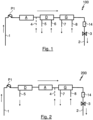
- Fig.1 shows a schematic representation of the basic structure of a first embodiment of a system 100 according to the invention for extracorporeal blood treatment, wherein the system 100 has a first inlet formed by a supply line 1 for introducing a blood stream to be treated into the system 100, three blood treatment devices A, D and G and a first outlet formed by a return line 2 for discharging a treated blood stream from the system 100.
- a first blood treatment device A is an adsorber device A designed for endotoxin adsorption.
- a second blood treatment device D is designed as a dialysis device D, in particular for hemodialysis.
- a third blood treatment device G is an oxygenator for removing carbon dioxide (CO2) from the blood stream to be treated and for enriching the blood stream to be treated with oxygen (02).
- CO2 carbon dioxide
- the system 100 according to the invention shown is designed to be introduced into a human or animal bloodstream to produce an extracorporeal bloodstream, wherein for this purpose the supply line 1 can be connected to a first blood vessel of the patient to be treated or of an animal to be treated, in particular a vein or an artery, for removing a bloodstream to be treated and the return line 2 can be connected to the first blood vessel or a second blood vessel, in particular a vein, for returning a treated bloodstream to the intracorporeal bloodstream of the patient or the animal.
- the system can preferably be connected to a double-lumen cannula which allows the creation of a veno-venous, extracorporeal blood circulation with just one vascular access. This means that the burden on the patient or animal being treated is extremely low, as two separate accesses to two separate vessels do not have to be created. Furthermore, the risk of infection is reduced.
- the three blood treatment devices A, D and G are connected in series, ie sequentially, with respect to a blood flow direction of a blood stream flowing through the system 100, which is indicated by the arrows in Fig.1
- the individual blood treatment devices A, D and G are part of a common treatment device according to the invention and are held by a common base, in particular fastened to a common carrier, the individual components of the system 100 being connected to one another by corresponding hose lines in such a way that blood can flow through them sequentially, ie one after the other.
- an adsorber device A a dialysis device D and a gas exchange device G enables combined blood treatment, in particular the combination of adsorption therapy, in the present case the combination of sepsis therapy with dialysis therapy and the removal of CO2 from the blood and/or enrichment of the blood with oxygen (02) in a single, common extracorporeal blood circuit.
- a system 100 according to the invention thus enables simultaneous blood treatment by means of adsorption, dialysis and gas exchange with the blood volume of just one extracorporeal blood circuit.
- the adsorber device A is designed in this embodiment of a system 100 according to the invention for sepsis therapy.
- Adsorber devices as such for this purpose are basically known from the prior art. Since volume fractions are removed from the blood mass flow during blood treatment by means of the adsorber device A, a further, in particular fourth, inlet 4, for supplying a substitution agent to compensate for this volume loss, whereby in particular a liquid substitution agent, in particular an electrolyte solution, can be supplied.
- the dialysis device D has a dialyzer for hemodialysis, to which a dialysate or a dialysis fluid can be fed via a fifth inlet 6 and from which an effluent produced during the dialysis treatment can be discharged via a second outlet 5.
- Dialysis devices of this type are also basically known from the prior art.
- the gas exchange device G is in the Fig.1
- the system 100 according to the invention shown is designed as an oxygenator G, wherein with the aid of the oxygenator G, carbon dioxide (CO2) is removed from the blood flowing through it with the aid of a defined gas which can be fed to the oxygenator via a further, in particular sixth, inlet 8, and which can be discharged via a third outlet 7.
- the blood flowing through the oxygenator G can also be enriched with the defined gas which can be fed to the oxygenator via the sixth inlet 8 and which in this case is oxygen (02).
- Oxygenators of this type are also basically known from the prior art.
- the oxygenator G can, for example, be an iLA ® Membrane Ventilator IL-1000-01 from Novalung GmbH.
- a first pump P1 designed as a blood pump is provided, wherein the first blood pump P1 can be controlled by means of a control device (not shown here), which is also part of the system 100 according to the invention, to control and/or regulate the blood flow.
- the first blood pump P1 can be a hose roller pump.
- the system according to the invention has a centrifugal pump as the first pump.
- This can be a diagonal pump designed as a rotor pump, preferably as in the EN 10 2010 024 650 A1 described.
- the size of the blood pump P1, in particular their connection cross-sections, are selected depending on the blood volume of the patient or the animal to be treated.
- the system has several pressure sensor devices (not shown here), wherein in this embodiment of a system 100 according to the invention a corresponding pressure sensor device is arranged immediately before and immediately after a blood treatment device A, D or G.
- a transmembrane pressure prevailing in the respective blood treatment device A, D and/or G can be determined in this way. Since the efficiency of the respective blood treatment basically depends on the respective transmembrane pressure prevailing and this should be within a certain range for optimal treatment success depending on the respective blood treatment device, the blood flow can be adjusted in this way, in particular by appropriately controlling the blood pump P1, at least for at least one of the three blood treatment devices A, D and G, in such a way that an advantageous transmembrane pressure is established in each case.
- the system 100 further comprises a gas bubble detection device 14 arranged downstream of the three blood treatment devices A, D and G in the direction of blood flow for detecting a gas bubble in the blood stream, as well as a shut-off valve 3 in the return line 2, downstream of the gas bubble detection device 14. If a gas bubble is detected in the blood stream by means of the gas bubble detection device 14, the shut-off valve 3 is closed, the first blood pump P1 is switched off and an alarm is triggered. This can prevent the gas bubble is returned with the bloodstream into the intracorporeal bloodstream of the patient or animal and leads to a life-threatening condition or even death.
- the system 100 according to the invention described here is designed for a blood flow in a range of 0.05 to 5I per minute, in particular for a blood flow in a range of 0.1 to 3I, in particular for a range of 0.2 to 1I per minute, in particular for a range of 0.2 to 0.5I per minute.
- the surfaces of the lumens of the system 100 that come into contact with the bloodstream can be provided with a biocompatible and at least partially with at least one functional coating, in particular with an antibacterial, anticoagulant and/or anti-inflammatory coating.
- the adsorber device A is arranged in the direction of blood flow upstream of the dialysis device D, whereby the dialysis device D is in turn arranged upstream of the gas exchange device G in the direction of blood flow.
- This arrangement has the advantage that an undiluted blood stream can be supplied to the adsorber device A, whereby a high effectiveness of the adsorption treatment can be ensured.
- undesirable, non-specific binding of ions or pH shifts can occur in the adsorber device A, which can be caused by a dialysis treatment carried out downstream of the blood with a Fig.1 shown sequence of the individual blood treatment devices A, D and G can be compensated by the dialysis device D.
- the dialysis device D can act downstream of the adsorber device A in the direction of blood flow as a further safety system against undesirable particle entry from the adsorber device A arranged upstream of the bloodstream.
- the arrangement of the gas exchange device G after the adsorber device A in the direction of blood flow has the advantage that an enrichment of the blood stream with carbon dioxide (CO2) by supplying the substitution product to the adsorber device A (which in the case of Fig.1 shown embodiment via the fourth inlet 4 after the adsorber device and before the dialysis device) and by a dialysis fluid possibly loaded with carbon dioxide (CO2) (which can be supplied to the system 100 in this embodiment via the fifth inlet 6) using the gas exchange device G before the treated blood stream is returned to the intracorporeal bloodstream of the patient or animal.
- CO2 carbon dioxide
- a subsituate in particular an additional amount of subsituate, can preferably also be supplied to the blood stream via the inlet 4 to compensate for the loss of fluid in the dialysis device D.
- the system can also have a further inlet in the direction of blood flow after the dialysis device D for adding the subsituate to compensate for the loss of fluid and/or volume in the adsorber device A and/or the dialysis device D.
- the individual blood treatment devices A, D and G of the system 100 according to the invention each have exchangeable treatment modules, which each comprise the complete treatment path and can be easily replaced like a spare part.
- the system 100 according to the invention can be easily and quickly adapted to the respective required treatment.
- the adsorber device A can be quickly and easily reconfigured from an adsorber device A for endotoxin adsorption to an adsorber device A for cytokine adsorption, for which specifically designed adsorber treatment modules are required depending on the application.
- the dialysis device D of the system 100 can be reconfigured from a dialysis device D designed for hemodialysis into a dialysis device D designed for hemofiltration or hemodiafiltration.
- the gas exchange device G of the system 100 according to the invention can also be adapted, whereby, depending on the required treatment, a gas exchange treatment module can be used which is designed only for the pure removal of CO2 from the blood stream or a gas exchange treatment module which additionally enables the possibility of enriching the blood stream to be treated with oxygen (02) or another gas or a gas mixture.
- the individual inlets and outlets can also be adapted and/or reconfigured, in particular with regard to their arrangement within the system, in particular with regard to their arrangement before and/or after the respective blood treatment devices.
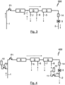
- Fig. 2 shows a second embodiment of a system 200 according to the invention for extracorporeal blood treatment, wherein components with the same functionality have the same reference numerals.
- the second embodiment of a second system 200 according to the invention for extracorporeal blood treatment which is also only shown schematically, is basically similar in structure to that shown in FIG. Fig.1 described first embodiment of a system 100 according to the invention for extracorporeal blood treatment, but differs from the system described with reference to Fig.1 described inventive system 100 that the sequence of the three blood treatment devices A, D and G in the Fig. 2 illustrated inventive system 200 is different and furthermore the dialysis device D is not designed for hemodialysis and accordingly does not have a dialyzer, but only for hemofiltration and accordingly has a hemofilter.
- the system 200 does not have a fifth inlet 6 for supplying a dialysate, since the hemofiltration does not require the supply of an additional dialysis fluid and only an effluent arising during the hemofiltration needs to be drained off, which in the Fig. 2 shown system can also be discharged via the second outlet 5.
- FIG. 2 The embodiment of a system 200 according to the invention for extracorporeal blood treatment, in which the dialysis device D is arranged in the direction of blood flow upstream of the adsorber device A and thus the dialysis device D is flowed through with the blood stream to be treated upstream of the adsorber device A, has the advantage that the blood stream is concentrated by removing the filtration quantity (effluent) in the hemofilter of the dialysis device D and thus a more concentrated blood stream can be supplied to the adsorber device A compared to the system 100 according to the invention from Fig.1 This allows a higher effectiveness of the adsorption treatment to be achieved. Consequently, the Fig. 2 An improved adsorption treatment can be achieved with the inventive system 200 shown.
- an undesirable charging or enrichment of the blood mass flow with carbon dioxide (CO2) as a result of the addition of a CO2-loaded substitute via the fourth inlet 4 can be compensated before it is returned to the intracorporeal bloodstream of the patient or the animal to be treated.
- CO2 carbon dioxide
- the supply of a more concentrated blood stream into adsorber device A may increase the risk of clotting, especially in adsorber device A.
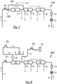
- the pressure sensor devices provided immediately before and immediately after the three blood treatment devices A, D and G can prevent Clotting can, however, be detected quickly and reliably and in particular by the additional addition of an anticoagulant to the bloodstream, for example by adding citrate via inlet 9 (see Fig.4 ), can be largely prevented.
- the respective adsorber device A or the respective blood treatment devices A, D and/or G affected by clotting or their respective treatment module forming a treatment section can be replaced.
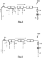
- Fig.3 shows a third embodiment of a system 300 according to the invention for extracorporeal blood treatment, wherein this system 300 is basically constructed similarly to the two previously described systems 100 and 200 according to the invention, but also differs in the order of the arrangement of the individual blood treatment devices A, G and D from the two previously described embodiments of systems 100 and 200 according to the invention for extracorporeal blood treatment.
- the adsorber device A is also the first to be flowed through by the blood mass flow to be treated.
- the gas exchange device G is then flowed through first, and only then the dialysis device D.
- the dialysis device D in the Fig.3 illustrated embodiment of a system 300 according to the invention is also designed only for hemofiltration and not for hemodialysis, the blood flow can no longer be charged after the gas exchange device G due to an exchange with a CO2-laden dialysate, since no dialysate is supplied to this dialysis device, since this is not required for hemofiltration.
- the arrangement of the gas exchange device G downstream of the adsorber device A ensures that a potentially undesirable CO2 loading of the blood mass flow can be compensated by supplying a CO2-loaded substitute via the fourth inlet 4.
- the arrangement downstream of the adsorber device A of the dialysis device D in the direction of blood flow, the dialysis device D can also act in this case as a safety-relevant filter stage against undesirable particle entry into the adsorber device A arranged upstream of the bloodstream.
- undesirable, non-specific, additional ion bonds and/or pH value shifts that may have arisen in the adsorber device A can also be compensated for by means of the dialysis device D with this arrangement or with this system 300 according to the invention.
- the hemofilter downstream of the gas exchange device G generates a dynamic pressure in the gas exchanger G, which has a beneficial effect on the function of the gas exchanger G.
- Fig.4 shows a fourth embodiment of a system 400 according to the invention for extracorporeal blood treatment, this embodiment representing a particularly preferred embodiment of a system according to the invention for extracorporeal blood treatment and also based on the Fig.1 described, first embodiment of a system 100 according to the invention.
- this system 400 has a second inlet 9 and a third inlet 11, via each of which a composition can be supplied to the bloodstream.
- a first composition which is preferably held in a bag 10, can be supplied to the blood mass flow to be treated via the second inlet 9 with the aid of a second pump P2, wherein the system 400 in this case is designed such that the first composition can be supplied to the blood flow immediately after removal from the intracorporeal blood circulation of the patient or animal to be treated, in particular in the direction of blood flow before the first blood pump P1 and in particular before the first blood treatment device through which the blood flow to be treated flows.
- system 400 is designed to supply a liquid citrate solution as an anticoagulant to the blood stream to be treated via the second inlet 9 with the aid of the second pump P2.
- a second composition in particular a calcium solution to compensate for the calcium loss caused during hemodialysis in the dialysis device D, can be supplied to the system via the third inlet 11 by means of a third pump P3.
- the second composition is supplied via the third inlet 11 immediately before the treated blood flow is returned to the patient, in particular after the shut-off valve 3. It is of course also possible to arrange the third inlet in the direction of blood flow before the shut-off valve 3.
- the system 400 according to the invention shown is particularly suitable for treatment in an extracorporeal blood circuit with a veno-venous access, ie in particular for CVVHD, in which the blood stream to be treated is taken from a vein of the patient or animal to be treated and the treated blood stream is returned to a vein.
- a veno-venous access ie in particular for CVVHD
- a substitution agent can be supplied to the blood stream preferably via an additional inlet 4 in the direction of blood flow after the adsorber device A and before the dialysis device D to compensate for the loss of fluid in the adsorber device A and/or the dialysis device D.
- the system can also have an inlet 4 in the direction of blood flow after the dialysis device D for adding the substitution agent to compensate for the loss of fluid and/or volume in the adsorber device A and/or the dialysis device D.
- Such a system is particularly suitable for post-CVVHDF.
- Fig.5 shows a fifth embodiment of a system 500 according to the invention for extracorporeal blood treatment, which is also based on the Fig.1 illustrated inventive system 100, but differs from the system 100 of Fig.1 differs in that the adsorber device A is arranged after the gas exchange device G, in particular after the gas exchange device G and after the dialysis device D.
- This arrangement has the advantage that the increased back pressure generated at the adsorber device A increases the pressure gradient in the gas exchange device G at the gas exchange membrane, whereby an improved gas exchange can be achieved.
- the substitute to compensate for the volume loss in the adsorber device A is preferably, as in Fig.5 shown, is added to the blood stream via the inlet 4 before the gas exchange device G.
- addition before the dialysis device D is also advantageously possible. In this way, an undesirable CO2 charge by the substitution agent can be compensated by means of the gas exchange device G arranged downstream.
- Fig.6 shows a sixth embodiment of a system 600 according to the invention for extracorporeal blood treatment, which is based on the Fig.5 illustrated inventive system 500, but differs from the system 500 in that Fig.5 differs in that the gas exchange device G in this case is arranged in front of the dialysis device D, which in this case is only designed for hemofiltration and not for hemodialysis.
- This arrangement has the advantage that the back pressure in front of the dialysis device D and in front of the adsorber device A each increases the pressure gradient within the gas exchange device G at the gas exchange membrane, whereby the efficiency of the gas exchange can be increased.
- the substituate is also added to the blood stream via the inlet 4 upstream of the gas exchange device G to compensate for the volume loss in the adsorber device A, so that an undesirable CO2 charge by the substituate can be compensated by means of the gas exchange device G arranged downstream.
- the dialysis device D is designed for hemofiltration, which does not require dialysate, an undesirable CO2 build-up by the dialysate can be avoided.
- Fig.7 shows a seventh embodiment of a system 700 according to the invention for extracorporeal blood treatment, which is also based on the Fig.1 shown inventive system 100, but in which a bypass device 13 is additionally present with a bypass line 13A and a bypass valve 13B, which allows the blood flow to be treated to be diverted around the adsorber device A.
- This system 700 has the advantage that blood treatment with or without adsorption treatment is possible. This significantly increases the flexibility with regard to the possible uses of a system according to the invention, since adsorption treatment is not indicated in all cases for blood treatment, or a clotted or almost completely loaded or saturated adsorber can be bypassed.
- the bypass valve 13B is preferably designed such that a blood stream to be treated is guided either completely through the adsorber device downstream of the bypass valve 13B in the direction of blood flow or completely past the adsorber device A via the bypass line 13A.
- the system has a correspondingly designed bypass device for each of the blood treatment devices A, D, G, so that with a system according to the invention, optionally an adsorption treatment, and/or a gas exchange and/or a dialysis treatment is possible.
- Fig.8 shows an eighth embodiment of a system 800 according to the invention, which is based on the system 100 of Fig.1 based, wherein in this embodiment the first blood treatment device, instead of an adsorber device A, is a plasma separation device PT in the form of a plasma filter PT, via which, with the aid of a further, in particular third, pump P3, separated blood plasma can be supplied to a blood plasma disposal container W via a line 16 which forms a fourth outlet for the removal of separated blood plasma.
- the first blood treatment device instead of an adsorber device A, is a plasma separation device PT in the form of a plasma filter PT, via which, with the aid of a further, in particular third, pump P3, separated blood plasma can be supplied to a blood plasma disposal container W via a line 16 which forms a fourth outlet for the removal of separated blood plasma.
- fresh plasma can be supplied to the blood stream as a replacement for the amount of blood plasma removed, in particular with the aid of a further, in particular fourth pump P4.
- Fig.9 shows a ninth embodiment of a system 900 according to the invention, which is based on the system 800 of Fig.8 based, wherein in this embodiment, the separated plasma is not fed to a blood plasma disposal container W, but is guided by means of a hose line, in particular by means of a bypass line, through a blood treatment device in the form of an adsorber device A, wherein the treated plasma is fed back into the remaining blood stream after the adsorption treatment, in particular into the main line.
- Fig.10 shows a tenth embodiment of a system 1000 according to the invention, which is based on the system 900 of Fig.9
- the separated plasma is not fed to the rest of the bloodstream after the adsorption treatment, but to the plasma separation device PT for recirculation in a bypass circuit. This allows improved plasma separation and/or adsorption treatment to be achieved.
Landscapes
- Health & Medical Sciences (AREA)
- Heart & Thoracic Surgery (AREA)
- Vascular Medicine (AREA)
- Life Sciences & Earth Sciences (AREA)
- General Health & Medical Sciences (AREA)
- Anesthesiology (AREA)
- Biomedical Technology (AREA)
- Hematology (AREA)
- Veterinary Medicine (AREA)
- Animal Behavior & Ethology (AREA)
- Engineering & Computer Science (AREA)
- Public Health (AREA)
- Cardiology (AREA)
- Urology & Nephrology (AREA)
- Emergency Medicine (AREA)
- Pulmonology (AREA)
- External Artificial Organs (AREA)
Claims (14)
- Système (100, 200, 300, 400, 500, 600, 700, 800, 900, 1000) pour le traitement extracorporel de sang, dans lequel le système (100, 200, 300, 400, 500, 600, 700, 800, 900, 1000) comporte- une première entrée (1) pour l'introduction d'un flux sanguin à traiter dans le système (100, 200, 300, 400, 500, 600, 700, 800, 900, 1000),- au moins un premier dispositif de traitement de sang (A, PT),- un deuxième dispositif de traitement de sang (D),- un troisième dispositif de traitement de sang (G) et- une première sortie (2) pour l'évacuation d'un flux sanguin traité hors du système (100, 200, 300, 400, 500, 600, 700, 800, 900, 1000),dans lequel le premier dispositif de traitement de sang (A, PT) est ou comporte un dispositif adsorbeur (A) pour l'élimination d'au moins un pathogène étranger au corps et/ou d'au moins un pathogène propre au corps et/ou un dispositif de séparation de plasma (PT) pour la séparation d'un plasma sanguin par rapport aux composants sanguins restants,dans lequel le deuxième dispositif de traitement de sang (D) est conçu en tant que dispositif de dialyse (D), en particulier en tant que dispositif de dialyse (D) pour la thérapie de remplacement rénal, etdans lequel le troisième dispositif de traitement de sang (G) est conçu en tant que dispositif d'échange gazeux (G), en particulier en tant que dispositif d'échange gazeux (G) pour l'élimination au moins partielle de CO2 depuis un flux sanguin s'écoulant à travers le dispositif d'échange gazeux (G) et/ou pour l'introduction d'un gaz ou d'un mélange gazeux jusque dans un flux sanguin s'écoulant à travers le dispositif d'échange gazeux (G), etdans lequel les trois dispositifs de traitement de sang (A et/ou PT, D, G) sont, dans un état d'utilisation fonctionnellement conforme du système (100, 200, 300, 400, 500, 600, 700, 800, 900, 1000) et par rapport à une direction de flux sanguin d'un flux sanguin à traiter, montés séquentiellement en série entre la première entrée (1) et la première sortie (2) du système et peuvent successivement être traversés par écoulement et de façon extracorporelle par un flux sanguin à traiter.
- Système (100, 200, 300, 400, 500, 600, 700, 800, 900, 1000) selon la revendication 1, caractérisé en ce que le premier dispositif de traitement de sang (A) est ou comporte un dispositif adsorbeur (A) conçu pour l'adsorption d'une endotoxine, d'une cytokine et/ou pour l'immuno-adsorption, dans lequel le dispositif adsorbeur (A) est en particulier conçu pour l'élimination d'au moins un médicament et/ou principe actif de remède et/ou d'au moins un poison végétal et/ou d'au moins un poison organique et/ou d'au moins une autre substance toxique et/ou pour l'élimination de bactéries, virus, champignons et/ou autres organismes et/ou d'au moins un complexe immun et/ou d'au moins une globuline immune et/ou d'au moins une substance de la réponse inflammatoire du corps et/ou des anticorps et/ou d'au moins un modèle moléculaire associé à un pathogène et/ou d'au moins une alarmine.
- Système (100, 200, 300, 400, 500, 600, 700, 800, 900, 1000) selon la revendication 1 ou 2, caractérisé en ce que le système (100, 200, 300, 400, 500, 600, 700, 800, 900, 1000) comporte au moins une première pompe (P1), en particulier une pompe (P1) conçue en tant que pompe à sang, pour la stimulation d'au moins une partie d'un flux sanguin à traiter, dans lequel la première pompe (P1) est agencée de préférence dans la direction de flux sanguin entre la première entrée (1) et le premier des trois dispositifs de traitement de sang (A, PT, D, G) dans la direction de flux sanguin et est en particulier conçue pour la stimulation de la totalité du flux sanguin à traiter.
- Système (400) selon l'une des revendications précédentes, caractérisé en ce que le système (400) comporte une autre, en particulier une deuxième, entrée (9), pour l'ajout d'une première composition dans le flux sanguin, en particulier dans le flux sanguin à traiter, dans lequel cette autre entrée (9) est agencée de préférence dans la direction de flux sanguin de sorte que la composition puisse être amenée au flux sanguin dans la direction de flux sanguin avant la première pompe (P1) et/ou avant le premier des trois dispositifs de traitement de sang (A, PT, D, G).
- Système (400) selon l'une des revendications précédentes, caractérisé en ce que le système (400) comporte une autre, en particulier une troisième, entrée (11) pour l'ajout d'une seconde composition dans le flux sanguin, en particulier dans le flux sanguin traité, dans lequel cette autre entrée (11) est agencée de préférence dans la direction de flux sanguin de sorte que la composition puisse être amenée au flux sanguin dans la direction de flux sanguin après le dispositif de dialyse (D), en particulier après le dernier dispositif de traitement de sang (A, PT, D, G) dans la direction de flux sanguin.
- Système (100, 200, 300, 400, 700, 800, 900, 1000) selon l'une des revendications précédentes, caractérisé en ce que le dispositif adsorbeur (A) et/ou le dispositif de séparation de plasma (PT) est agencé dans la direction de flux sanguin avant le dispositif d'échange gazeux (G) ou après le dispositif d'échange gazeux (G) .
- Système (100, 300, 400, 700, 800, 900, 1000) selon l'une des revendications précédentes, caractérisé en ce que le dispositif adsorbeur (A) et/ou le dispositif de séparation de plasma (PT) est agencé dans la direction de flux sanguin avant le dispositif de dialyse (D), dans lequel le dispositif de dialyse (D) est conçu de préférence pour l'hémodialyse et comporte en particulier un dialyseur ou
est caractérisé en ce que le dispositif adsorbeur (A) et/ou le dispositif de séparation de plasma (PT) est agencé dans la direction de flux sanguin après le dispositif de dialyse (D), dans lequel le dispositif de dialyse (D) est conçu de préférence pour l'hémofiltration et comporte en particulier un hémofiltre. - Système (100, 200, 400, 500, 800, 900, 1000) selon l'une des revendications précédentes, caractérisé en ce que le dispositif de dialyse (D) est agencé dans la direction de flux sanguin avant le dispositif d'échange gazeux (G) ou,
en ce que le dispositif de dialyse (D) est agencé dans la direction de flux sanguin après le dispositif d'échange gazeux (G), dans lequel le dispositif de dialyse (D) est conçu de préférence pour l'hémofiltration et comporte un hémofiltre. - Système (100, 200, 300, 400, 500, 600, 700, 800, 900, 1000) selon l'une des revendications précédentes, caractérisé en ce que le système (100, 200, 300, 400, 500, 600, 700, 800, 900, 1000) comporte au moins un équipement de capteur de pression pour l'établissement d'une pression d'écoulement du flux sanguin en un emplacement défini dans le système (100, 200, 300, 400, 500, 600, 700, 800, 900, 1000), dans lequel au moins un équipement de détection de pression est agencé de préférence dans la direction de flux sanguin immédiatement avant et/ou immédiatement après au moins un tronçon de traitement d'un dispositif de traitement de sang (A, PT, D, G).
- Système (100, 200, 300, 400, 500, 600, 700, 800, 900, 1000) selon l'une des revendications précédentes, caractérisé en ce que le système (100, 200, 300, 400, 500, 600, 700, 800, 900, 1000) comporte au moins un équipement de détection de bulle gazeuse (14) pour la détection d'une bulle gazeuse dans le flux sanguin.
- Système (100, 200, 300, 400, 500, 600, 700, 800, 900, 1000) selon l'une des revendications précédentes, caractérisé en ce que, dans le cas d'au moins un dispositif de traitement de sang (A, PT, D, G), un tronçon de traitement est formé au moins partiellement, de préférence entièrement, par un module de traitement interchangeable, en particulier par un module de traitement en forme de cartouche.
- Système (700) selon l'une des revendications précédentes, caractérisé en ce que le système (700) comporte au moins un équipement de contournement (13) qui peut être commuté pour le contournement d'au moins un dispositif de traitement de sang (A, D, G).
- Système (100, 200, 300, 400, 500, 600, 700, 800, 900, 1000) selon l'une des revendications précédentes, caractérisé en ce qu'au moins une composante du système (100, 200, 300, 400, 500, 600, 700, 800, 900, 1000) comporte, sur une surface entrant en contact avec le flux sanguin à traiter, un revêtement biocompatible et de préférence fonctionnel, en particulier un revêtement antibactérien, anticoagulant et/ou anti-inflammatoire.
- Dispositif de traitement pour le traitement extracorporel de sang, caractérisé en ce que le dispositif de traitement comporte un système (100, 200, 300, 400, 500, 600, 700, 800, 900, 1000) qui est conçu selon l'une des revendications 1 à 13, dans lequel le premier, le deuxième et le troisième dispositif de traitement de sang (A, PT, D, G) du système (100, 200, 300, 400, 500, 600, 700, 800, 900, 1000) sont agencés dans un logement commun et/ou sont reçus par une base commune.
Applications Claiming Priority (3)
| Application Number | Priority Date | Filing Date | Title |
|---|---|---|---|
| DE102016014892 | 2016-12-15 | ||
| DE102017210134.2A DE102017210134A1 (de) | 2016-12-15 | 2017-06-16 | System zur extrakorporalen Blutbehandlung, Behandlungsvorrichtung, Kit und Verfahren zum Betreiben eines Systems zur extrakorporalen Blutbehandlung |
| PCT/EP2017/082781 WO2018109070A1 (fr) | 2016-12-15 | 2017-12-14 | Système de traitement extracorporel du sang, dispositif de traitement, kit et procédé pour faire fonctionner un système de traitement extracorporel du sang |
Publications (2)
| Publication Number | Publication Date |
|---|---|
| EP3554577A1 EP3554577A1 (fr) | 2019-10-23 |
| EP3554577B1 true EP3554577B1 (fr) | 2024-08-07 |
Family
ID=60955006
Family Applications (2)
| Application Number | Title | Priority Date | Filing Date |
|---|---|---|---|
| EP17828684.5A Active EP3554578B1 (fr) | 2016-12-15 | 2017-12-14 | Dispositif de conduite de sang destiné à effectuer un traitement de sang extracorporel, système de traitement de sang |
| EP17828682.9A Active EP3554577B1 (fr) | 2016-12-15 | 2017-12-14 | Système de traitement extracorporel du sang et dispositif de traitement |
Family Applications Before (1)
| Application Number | Title | Priority Date | Filing Date |
|---|---|---|---|
| EP17828684.5A Active EP3554578B1 (fr) | 2016-12-15 | 2017-12-14 | Dispositif de conduite de sang destiné à effectuer un traitement de sang extracorporel, système de traitement de sang |
Country Status (5)
| Country | Link |
|---|---|
| US (2) | US11433173B2 (fr) |
| EP (2) | EP3554578B1 (fr) |
| CN (2) | CN110072568B (fr) |
| DE (2) | DE102017210134A1 (fr) |
| WO (2) | WO2018109070A1 (fr) |
Families Citing this family (19)
| Publication number | Priority date | Publication date | Assignee | Title |
|---|---|---|---|---|
| MX2020002828A (es) | 2017-09-17 | 2020-07-22 | Steven Paul Keller | Sistemas, dispositivos, y métodos para la eliminación extracorpórea de dióxido de carbono. |
| HRP20221335T1 (hr) | 2017-11-30 | 2022-12-23 | Regeneron Pharmaceuticals, Inc. | Upotreba antagonista vegf za liječenje angiogenih očnih poremećaja |
| US12064543B2 (en) * | 2018-07-03 | 2024-08-20 | The General Hospital Corporation | System and method for extracorporeal carbon monoxide removal with phototherapy |
| US20220062522A1 (en) * | 2018-12-25 | 2022-03-03 | Asahi Kasei Medical Co., Ltd. | Extracorporeal blood circulation system provided with blood purification device and blood component adjuster |
| DE102019105655A1 (de) | 2019-03-06 | 2020-09-10 | B.Braun Avitum Ag | Extrakorporales Blutleitungsset und Blutbehandlungsmaschine |
| DE102019106651A1 (de) | 2019-03-15 | 2020-09-17 | Fraunhofer-Gesellschaft zur Förderung der angewandten Forschung e.V. | Behandlungsvorrichtung und -verfahren zur extrakorporalen, Immuntoleranz-steigernden Blutbehandlung |
| DE102019115162A1 (de) * | 2019-06-05 | 2020-12-10 | Rheinisch-Westfälische Technische Hochschule (Rwth) Aachen | Vorrichtung für den Stoff- und/oder Energieaustausch zwischen zwei Medien und Verfahren zu dessen Herstellung |
| PL3763400T3 (pl) | 2019-07-09 | 2025-01-20 | Gambro Lundia Ab | Aparat do pozaustrojowego oczyszczania krwi |
| CN111166953A (zh) * | 2020-02-03 | 2020-05-19 | 深圳汉诺医疗科技有限公司 | 一种用于净化血液的体外循环系统及方法 |
| GB202004775D0 (en) * | 2020-03-31 | 2020-05-13 | Ucl Business Ltd | Apparatus |
| EP3900754B1 (fr) * | 2020-04-20 | 2024-10-02 | Gambro Lundia AB | Appareil de traitement sanguin extracorporel |
| DE102020111867A1 (de) | 2020-04-30 | 2021-11-04 | Fresenius Medical Care Deutschland Gmbh | Hämodialysevorrichtung mit Gasaustauscher |
| CN111840780B (zh) * | 2020-06-24 | 2022-07-12 | 安徽通灵仿生科技有限公司 | 适用于ecmo期间血液净化装置的管路适配器 |
| CN113041425A (zh) * | 2021-04-27 | 2021-06-29 | 东劢医疗科技(苏州)有限公司 | 一种用于医疗设备的调节装置 |
| WO2023081449A1 (fr) * | 2021-11-07 | 2023-05-11 | Rce Technologies, Inc. | Système et procédé de détermination de marqueurs infraspectraux à l'aide d'une optique infrarouge transdermique |
| JP2024064862A (ja) * | 2022-10-28 | 2024-05-14 | 株式会社ジェイ・エム・エス | 血液浄化システム及び中間システム |
| CN120731106A (zh) * | 2022-11-07 | 2025-09-30 | 斯塔夫罗医疗公司 | 单腔或双腔系统 |
| DE102023102145A1 (de) * | 2023-01-30 | 2024-08-01 | Fresenius Medical Care Deutschland Gmbh | Blutbehandlungsvorrichtung zum Gasaustausch |
| CN118767235A (zh) * | 2024-06-24 | 2024-10-15 | 恩基(苏州)智慧医疗科技有限公司 | 一种快换式血液透析用透析机 |
Family Cites Families (40)
| Publication number | Priority date | Publication date | Assignee | Title |
|---|---|---|---|---|
| JPH06104122B2 (ja) | 1985-09-19 | 1994-12-21 | 東レ株式会社 | β▲下2▼−ミクログロブリン除去カラム |
| US5368555A (en) * | 1992-12-29 | 1994-11-29 | Hepatix, Inc. | Organ support system |
| DE19622184A1 (de) | 1996-06-03 | 1997-12-04 | Joern Martens | Tragbares Gerät zur Langzeit-Perfusion von menschlichen und tierischen Geweben, als Herz-Lungen-Nieren-Leber-Maschine, für die umfassende, funktionell stützende Behandlung und besonders auch für die lebenserhaltende Notfall-Perfusion, zur Notfall-Versorgung von Patienten |
| EP1693402A3 (fr) | 1997-01-07 | 2009-05-27 | Kaneka Corporation | Particules cellulosiques, objets sphériques comportant des particules de polymère reticule et agent adsorbant de purification de fluides corporels |
| WO2000064510A1 (fr) * | 1999-04-23 | 2000-11-02 | Nephros Therapeutics, Inc. | Circuit extra-corporel et methodes correspondantes |
| BR0207303A (pt) * | 2001-02-07 | 2004-06-15 | Nephros Inc | Método e aparelho para um módulo de fornecimento de hemodiafiltração |
| DE10224750A1 (de) * | 2002-06-04 | 2003-12-24 | Fresenius Medical Care De Gmbh | Vorrichtung zur Behandlung einer medizinischen Flüssigkeit |
| US8029454B2 (en) * | 2003-11-05 | 2011-10-04 | Baxter International Inc. | High convection home hemodialysis/hemofiltration and sorbent system |
| WO2005074657A2 (fr) * | 2004-02-02 | 2005-08-18 | The General Hospital Corporation | Dispositifs de support d'organe modifies |
| CN101005871A (zh) | 2004-04-27 | 2007-07-25 | 生命治疗有限公司 | 代谢性解毒系统和方法 |
| DE102004023080B4 (de) * | 2004-05-11 | 2009-01-15 | Fresenius Medical Care Deutschland Gmbh | Verfahren und Vorrichtung zur Überwachung der Zufuhr von Substitutionsflüssigkeit während einer extrakorporalen Blutbehandlung |
| US7955504B1 (en) | 2004-10-06 | 2011-06-07 | State Of Oregon Acting By And Through The State Board Of Higher Education On Behalf Of Oregon State University | Microfluidic devices, particularly filtration devices comprising polymeric membranes, and method for their manufacture and use |
| DE102005039446B4 (de) | 2005-08-18 | 2009-06-25 | Ilias-Medical Gmbh | Vorrichtung zur An- und Abreicherung von Stoffen in einer Flüssigkeit |
| EP2155284B1 (fr) | 2007-06-06 | 2018-10-17 | Georgia Tech Research Corporation | Nouveau système de gestion de fluide pour hémofiltration continue précise |
| EP2246080B1 (fr) * | 2007-10-12 | 2016-02-10 | DEKA Products Limited Partnership | Système de circulation sanguine extracorporel |
| DE102008024835A1 (de) * | 2008-05-23 | 2009-12-10 | Maquet Cardiopulmonary Ag | Universell anwendbares optimiertes Perfusionssystem |
| DE102008045621A1 (de) | 2008-09-03 | 2010-03-04 | Novalung Gmbh | Gastransfervorrichtung und Verwendung einer strukturierten Membran |
| CN201320317Y (zh) | 2008-12-26 | 2009-10-07 | 南京大学医学院附属鼓楼医院 | 混合型生物人工肝体外支持装置 |
| DE102009037015A1 (de) | 2009-08-07 | 2011-02-17 | Michael Hajek | Vorrichtung und Verfahren zur Eliminierung von bioschädlichen Stoffen aus Körperflüssigkeiten |
| DE102009051806A1 (de) * | 2009-11-03 | 2011-05-05 | Gambro Lundia Ab | Vorrichtung zur Unterstützung der Leberfunktion |
| DE102009060668A1 (de) * | 2009-12-28 | 2011-06-30 | Fresenius Medical Care Deutschland GmbH, 61352 | Vorrichtung und Verfahren zur Überwachung einer extrakorporalen Blutbehandlung |
| NL1038359C2 (en) * | 2010-03-31 | 2012-06-27 | Aquamarijn Res B V | Device and method for separation of circulating tumor cells. |
| DE102010024650A1 (de) | 2010-05-04 | 2011-11-10 | Medos Medizintechnik Ag | Blutpumpe mit einem Rotor |
| ITMI20110441A1 (it) | 2011-03-21 | 2012-09-22 | Gambro Lundia Ab | Apparecchiatura per il trattamento extracorporeo di sangue. |
| WO2013019994A2 (fr) * | 2011-08-02 | 2013-02-07 | Medtronic, Inc. | Système d'hémodialyse possédant un circuit de flux avec un volume à conformité régulée |
| FR2980712B1 (fr) | 2011-10-03 | 2013-10-04 | Physidia | Machine de dialyse comprenant des moyens d'ultrafiltration et de retrofiltration |
| CN102500003B (zh) | 2011-11-30 | 2015-06-10 | 虞文魁 | 多功能体外生命支持与治疗系统一体化装置 |
| CN202699682U (zh) * | 2012-02-28 | 2013-01-30 | 旭化成医疗株式会社 | 过滤器 |
| DE102012018628A1 (de) | 2012-09-21 | 2014-03-27 | Fresenius Medical Care Deutschland Gmbh | Vorrichtung und Verfahren zur Erkennung der Rezirkulation während einer extrakorporalen Blutbehandlung |
| PL2735326T3 (pl) | 2012-11-26 | 2017-08-31 | Gambro Lundia Ab | Układ wspomagania wątroby |
| DE102012025052A1 (de) * | 2012-12-20 | 2014-06-26 | Fresenius Medical Care Deutschland Gmbh | Hämodiafiltrationsverfahren |
| US10010663B2 (en) * | 2013-02-01 | 2018-07-03 | Medtronic, Inc. | Fluid circuit for delivery of renal replacement therapies |
| US9302041B2 (en) * | 2013-03-15 | 2016-04-05 | Haemonetics Corporation | Blood-donation system |
| CN103251996B (zh) | 2013-04-02 | 2015-09-30 | 周春华 | 便携式多器官功能支持一体化治疗机 |
| DE102013012366B3 (de) * | 2013-07-25 | 2014-12-31 | Fresenius Medical Care Deutschland Gmbh | Extrakorporale Blutbehandlungsvorrichtung |
| DE102013018444A1 (de) | 2013-11-05 | 2015-05-07 | Novalung Gmbh | Vorrichtung mit einer Fluidpumpe, mindestens zwei Bauchdeckenzugängen und Fluidpumpe und Bauchdecke verbindenden Schläuchen |
| WO2016103290A1 (fr) | 2014-12-22 | 2016-06-30 | Extra Corporeal Solutions S.R.L. | Appareil pour le traitement de sang |
| CN104800902B (zh) * | 2015-04-30 | 2017-02-22 | 北京迈淩医疗技术发展有限公司 | 用于救治多器官功能衰竭的体外循环生命支持设备 |
| EP3090768A1 (fr) | 2015-05-07 | 2016-11-09 | Novalung GmbH | Dispositif doté de section d'admission destiné au traitement d'un liquide biologique |
| EP3090769A1 (fr) | 2015-05-07 | 2016-11-09 | Novalung GmbH | Dispositif portatif d'échange gazeux |
-
2017
- 2017-06-16 DE DE102017210134.2A patent/DE102017210134A1/de not_active Ceased
- 2017-09-20 DE DE102017216689.4A patent/DE102017216689A1/de active Pending
- 2017-12-14 CN CN201780077600.XA patent/CN110072568B/zh active Active
- 2017-12-14 US US16/468,299 patent/US11433173B2/en active Active
- 2017-12-14 WO PCT/EP2017/082781 patent/WO2018109070A1/fr not_active Ceased
- 2017-12-14 EP EP17828684.5A patent/EP3554578B1/fr active Active
- 2017-12-14 WO PCT/EP2017/082783 patent/WO2018109071A1/fr not_active Ceased
- 2017-12-14 US US16/468,297 patent/US11707560B2/en active Active
- 2017-12-14 EP EP17828682.9A patent/EP3554577B1/fr active Active
- 2017-12-14 CN CN201780078055.6A patent/CN110072569B/zh active Active
Also Published As
| Publication number | Publication date |
|---|---|
| WO2018109071A1 (fr) | 2018-06-21 |
| US11433173B2 (en) | 2022-09-06 |
| CN110072568A (zh) | 2019-07-30 |
| US20200069860A1 (en) | 2020-03-05 |
| US20200069859A1 (en) | 2020-03-05 |
| CN110072569A (zh) | 2019-07-30 |
| DE102017210134A1 (de) | 2018-06-21 |
| CN110072568B (zh) | 2022-02-22 |
| EP3554577A1 (fr) | 2019-10-23 |
| WO2018109070A1 (fr) | 2018-06-21 |
| EP3554578B1 (fr) | 2024-08-07 |
| CN110072569B (zh) | 2023-07-28 |
| US11707560B2 (en) | 2023-07-25 |
| DE102017216689A1 (de) | 2018-06-21 |
| EP3554578A1 (fr) | 2019-10-23 |
Similar Documents
| Publication | Publication Date | Title |
|---|---|---|
| EP3554577B1 (fr) | Système de traitement extracorporel du sang et dispositif de traitement | |
| DE60031966T2 (de) | Extrakorporaler kreislauf | |
| DE2827256C2 (de) | Hämodialyse-Vorrichtung | |
| DE69932984T2 (de) | System und Behandlung zur Unterdrückung von Sepsis | |
| DE3101159C2 (de) | Verfahren zur Reinigung von Blut und künstliche Niere zur Durchführung des Verfahrens | |
| EP0587101B1 (fr) | Dispositif pour l'élimination des ions aluminium du sang et solution utilisée dans ce dipositif | |
| DE68926197T2 (de) | Vorrichtung zur Abtrennung von Plasma in vivo | |
| DE60120761T3 (de) | Hämodiafiltration/hämofiltrations-patronen | |
| US6787040B2 (en) | Method and system for colloid exchange therapy | |
| DE60127657T2 (de) | Blutreinigungssystem | |
| EP1244480A1 (fr) | Systeme d'hemodiafiltration | |
| DE69025053T2 (de) | Einrichtung zur Blutreinigung | |
| EP2934619B1 (fr) | Dispositif d'élimination des toxines liées aux protéines dans le plasma sanguin | |
| EP1867354B1 (fr) | Dispositif destiné à l'enlèvement de substances liées aux protéines | |
| EP2190498A1 (fr) | Procédé et dispositif pour faire des économies de diafiltrat | |
| DE69934248T2 (de) | Anlage zur nicht-isosmotischen diafiltration | |
| EP2440265B1 (fr) | Dispositif de dialyse | |
| WO2019122407A2 (fr) | Aspects de traitement pour la réduction de la teneur en dioxyde de carbone dans le sang | |
| DE3147377A1 (de) | Verfahren und vorrichtung zur extrakorporalen entfernung von an eiweisskoerpern gebundenen toxinen | |
| DE4102693C2 (fr) | ||
| EP3185926A1 (fr) | Système d'élimination des médiateurs pro-inflammatoires ainsi que des granulocytes et des monocytes du sang | |
| DE102012020497A1 (de) | Verfahren zur extrakorporalen Behandlung von Blut und Vorrichtung zur Durchführung des Verfahrens | |
| DE19540079A1 (de) | Dialysegerät | |
| DE102021109242A1 (de) | Extrakorporaler Kreislauf zur Decapneisierung von organischen Fluiden | |
| WO2017093553A1 (fr) | Solutions d'hémofiltration pour le traitement d'accidents vasculaires cérébraux |
Legal Events
| Date | Code | Title | Description |
|---|---|---|---|
| STAA | Information on the status of an ep patent application or granted ep patent |
Free format text: STATUS: UNKNOWN |
|
| STAA | Information on the status of an ep patent application or granted ep patent |
Free format text: STATUS: THE INTERNATIONAL PUBLICATION HAS BEEN MADE |
|
| PUAI | Public reference made under article 153(3) epc to a published international application that has entered the european phase |
Free format text: ORIGINAL CODE: 0009012 |
|
| STAA | Information on the status of an ep patent application or granted ep patent |
Free format text: STATUS: REQUEST FOR EXAMINATION WAS MADE |
|
| 17P | Request for examination filed |
Effective date: 20190712 |
|
| AK | Designated contracting states |
Kind code of ref document: A1 Designated state(s): AL AT BE BG CH CY CZ DE DK EE ES FI FR GB GR HR HU IE IS IT LI LT LU LV MC MK MT NL NO PL PT RO RS SE SI SK SM TR |
|
| AX | Request for extension of the european patent |
Extension state: BA ME |
|
| DAV | Request for validation of the european patent (deleted) | ||
| DAX | Request for extension of the european patent (deleted) | ||
| STAA | Information on the status of an ep patent application or granted ep patent |
Free format text: STATUS: EXAMINATION IS IN PROGRESS |
|
| 17Q | First examination report despatched |
Effective date: 20220727 |
|
| P01 | Opt-out of the competence of the unified patent court (upc) registered |
Effective date: 20230514 |
|
| GRAP | Despatch of communication of intention to grant a patent |
Free format text: ORIGINAL CODE: EPIDOSNIGR1 |
|
| STAA | Information on the status of an ep patent application or granted ep patent |
Free format text: STATUS: GRANT OF PATENT IS INTENDED |
|
| INTG | Intention to grant announced |
Effective date: 20240318 |
|
| GRAS | Grant fee paid |
Free format text: ORIGINAL CODE: EPIDOSNIGR3 |
|
| GRAA | (expected) grant |
Free format text: ORIGINAL CODE: 0009210 |
|
| STAA | Information on the status of an ep patent application or granted ep patent |
Free format text: STATUS: THE PATENT HAS BEEN GRANTED |
|
| AK | Designated contracting states |
Kind code of ref document: B1 Designated state(s): AL AT BE BG CH CY CZ DE DK EE ES FI FR GB GR HR HU IE IS IT LI LT LU LV MC MK MT NL NO PL PT RO RS SE SI SK SM TR |
|
| REG | Reference to a national code |
Ref country code: GB Ref legal event code: FG4D Free format text: NOT ENGLISH |
|
| REG | Reference to a national code |
Ref country code: CH Ref legal event code: EP |
|
| REG | Reference to a national code |
Ref country code: DE Ref legal event code: R096 Ref document number: 502017016334 Country of ref document: DE |
|
| REG | Reference to a national code |
Ref country code: IE Ref legal event code: FG4D Free format text: LANGUAGE OF EP DOCUMENT: GERMAN |
|
| REG | Reference to a national code |
Ref country code: LT Ref legal event code: MG9D |
|
| REG | Reference to a national code |
Ref country code: NL Ref legal event code: MP Effective date: 20240807 |
|
| PG25 | Lapsed in a contracting state [announced via postgrant information from national office to epo] |
Ref country code: NO Free format text: LAPSE BECAUSE OF FAILURE TO SUBMIT A TRANSLATION OF THE DESCRIPTION OR TO PAY THE FEE WITHIN THE PRESCRIBED TIME-LIMIT Effective date: 20241107 |
|
| PG25 | Lapsed in a contracting state [announced via postgrant information from national office to epo] |
Ref country code: PT Free format text: LAPSE BECAUSE OF FAILURE TO SUBMIT A TRANSLATION OF THE DESCRIPTION OR TO PAY THE FEE WITHIN THE PRESCRIBED TIME-LIMIT Effective date: 20241209 Ref country code: FI Free format text: LAPSE BECAUSE OF FAILURE TO SUBMIT A TRANSLATION OF THE DESCRIPTION OR TO PAY THE FEE WITHIN THE PRESCRIBED TIME-LIMIT Effective date: 20240807 Ref country code: NL Free format text: LAPSE BECAUSE OF FAILURE TO SUBMIT A TRANSLATION OF THE DESCRIPTION OR TO PAY THE FEE WITHIN THE PRESCRIBED TIME-LIMIT Effective date: 20240807 Ref country code: GR Free format text: LAPSE BECAUSE OF FAILURE TO SUBMIT A TRANSLATION OF THE DESCRIPTION OR TO PAY THE FEE WITHIN THE PRESCRIBED TIME-LIMIT Effective date: 20241108 Ref country code: PL Free format text: LAPSE BECAUSE OF FAILURE TO SUBMIT A TRANSLATION OF THE DESCRIPTION OR TO PAY THE FEE WITHIN THE PRESCRIBED TIME-LIMIT Effective date: 20240807 |
|
| PG25 | Lapsed in a contracting state [announced via postgrant information from national office to epo] |
Ref country code: BG Free format text: LAPSE BECAUSE OF FAILURE TO SUBMIT A TRANSLATION OF THE DESCRIPTION OR TO PAY THE FEE WITHIN THE PRESCRIBED TIME-LIMIT Effective date: 20240807 |
|
| PG25 | Lapsed in a contracting state [announced via postgrant information from national office to epo] |
Ref country code: LV Free format text: LAPSE BECAUSE OF FAILURE TO SUBMIT A TRANSLATION OF THE DESCRIPTION OR TO PAY THE FEE WITHIN THE PRESCRIBED TIME-LIMIT Effective date: 20240807 |
|
| PG25 | Lapsed in a contracting state [announced via postgrant information from national office to epo] |
Ref country code: IS Free format text: LAPSE BECAUSE OF FAILURE TO SUBMIT A TRANSLATION OF THE DESCRIPTION OR TO PAY THE FEE WITHIN THE PRESCRIBED TIME-LIMIT Effective date: 20241207 |
|
| PG25 | Lapsed in a contracting state [announced via postgrant information from national office to epo] |
Ref country code: HR Free format text: LAPSE BECAUSE OF FAILURE TO SUBMIT A TRANSLATION OF THE DESCRIPTION OR TO PAY THE FEE WITHIN THE PRESCRIBED TIME-LIMIT Effective date: 20240807 |
|
| PG25 | Lapsed in a contracting state [announced via postgrant information from national office to epo] |
Ref country code: ES Free format text: LAPSE BECAUSE OF FAILURE TO SUBMIT A TRANSLATION OF THE DESCRIPTION OR TO PAY THE FEE WITHIN THE PRESCRIBED TIME-LIMIT Effective date: 20240807 Ref country code: RS Free format text: LAPSE BECAUSE OF FAILURE TO SUBMIT A TRANSLATION OF THE DESCRIPTION OR TO PAY THE FEE WITHIN THE PRESCRIBED TIME-LIMIT Effective date: 20241107 |
|
| PG25 | Lapsed in a contracting state [announced via postgrant information from national office to epo] |
Ref country code: RS Free format text: LAPSE BECAUSE OF FAILURE TO SUBMIT A TRANSLATION OF THE DESCRIPTION OR TO PAY THE FEE WITHIN THE PRESCRIBED TIME-LIMIT Effective date: 20241107 Ref country code: PT Free format text: LAPSE BECAUSE OF FAILURE TO SUBMIT A TRANSLATION OF THE DESCRIPTION OR TO PAY THE FEE WITHIN THE PRESCRIBED TIME-LIMIT Effective date: 20241209 Ref country code: PL Free format text: LAPSE BECAUSE OF FAILURE TO SUBMIT A TRANSLATION OF THE DESCRIPTION OR TO PAY THE FEE WITHIN THE PRESCRIBED TIME-LIMIT Effective date: 20240807 Ref country code: NO Free format text: LAPSE BECAUSE OF FAILURE TO SUBMIT A TRANSLATION OF THE DESCRIPTION OR TO PAY THE FEE WITHIN THE PRESCRIBED TIME-LIMIT Effective date: 20241107 Ref country code: NL Free format text: LAPSE BECAUSE OF FAILURE TO SUBMIT A TRANSLATION OF THE DESCRIPTION OR TO PAY THE FEE WITHIN THE PRESCRIBED TIME-LIMIT Effective date: 20240807 Ref country code: LV Free format text: LAPSE BECAUSE OF FAILURE TO SUBMIT A TRANSLATION OF THE DESCRIPTION OR TO PAY THE FEE WITHIN THE PRESCRIBED TIME-LIMIT Effective date: 20240807 Ref country code: IS Free format text: LAPSE BECAUSE OF FAILURE TO SUBMIT A TRANSLATION OF THE DESCRIPTION OR TO PAY THE FEE WITHIN THE PRESCRIBED TIME-LIMIT Effective date: 20241207 Ref country code: HR Free format text: LAPSE BECAUSE OF FAILURE TO SUBMIT A TRANSLATION OF THE DESCRIPTION OR TO PAY THE FEE WITHIN THE PRESCRIBED TIME-LIMIT Effective date: 20240807 Ref country code: GR Free format text: LAPSE BECAUSE OF FAILURE TO SUBMIT A TRANSLATION OF THE DESCRIPTION OR TO PAY THE FEE WITHIN THE PRESCRIBED TIME-LIMIT Effective date: 20241108 Ref country code: FI Free format text: LAPSE BECAUSE OF FAILURE TO SUBMIT A TRANSLATION OF THE DESCRIPTION OR TO PAY THE FEE WITHIN THE PRESCRIBED TIME-LIMIT Effective date: 20240807 Ref country code: ES Free format text: LAPSE BECAUSE OF FAILURE TO SUBMIT A TRANSLATION OF THE DESCRIPTION OR TO PAY THE FEE WITHIN THE PRESCRIBED TIME-LIMIT Effective date: 20240807 Ref country code: BG Free format text: LAPSE BECAUSE OF FAILURE TO SUBMIT A TRANSLATION OF THE DESCRIPTION OR TO PAY THE FEE WITHIN THE PRESCRIBED TIME-LIMIT Effective date: 20240807 |
|
| PG25 | Lapsed in a contracting state [announced via postgrant information from national office to epo] |
Ref country code: DK Free format text: LAPSE BECAUSE OF FAILURE TO SUBMIT A TRANSLATION OF THE DESCRIPTION OR TO PAY THE FEE WITHIN THE PRESCRIBED TIME-LIMIT Effective date: 20240807 Ref country code: RO Free format text: LAPSE BECAUSE OF FAILURE TO SUBMIT A TRANSLATION OF THE DESCRIPTION OR TO PAY THE FEE WITHIN THE PRESCRIBED TIME-LIMIT Effective date: 20240807 Ref country code: SM Free format text: LAPSE BECAUSE OF FAILURE TO SUBMIT A TRANSLATION OF THE DESCRIPTION OR TO PAY THE FEE WITHIN THE PRESCRIBED TIME-LIMIT Effective date: 20240807 |
|
| PG25 | Lapsed in a contracting state [announced via postgrant information from national office to epo] |
Ref country code: EE Free format text: LAPSE BECAUSE OF FAILURE TO SUBMIT A TRANSLATION OF THE DESCRIPTION OR TO PAY THE FEE WITHIN THE PRESCRIBED TIME-LIMIT Effective date: 20240807 |
|
| PG25 | Lapsed in a contracting state [announced via postgrant information from national office to epo] |
Ref country code: CZ Free format text: LAPSE BECAUSE OF FAILURE TO SUBMIT A TRANSLATION OF THE DESCRIPTION OR TO PAY THE FEE WITHIN THE PRESCRIBED TIME-LIMIT Effective date: 20240807 |
|
| PG25 | Lapsed in a contracting state [announced via postgrant information from national office to epo] |
Ref country code: SK Free format text: LAPSE BECAUSE OF FAILURE TO SUBMIT A TRANSLATION OF THE DESCRIPTION OR TO PAY THE FEE WITHIN THE PRESCRIBED TIME-LIMIT Effective date: 20240807 |
|
| REG | Reference to a national code |
Ref country code: DE Ref legal event code: R097 Ref document number: 502017016334 Country of ref document: DE |
|
| PLBE | No opposition filed within time limit |
Free format text: ORIGINAL CODE: 0009261 |
|
| STAA | Information on the status of an ep patent application or granted ep patent |
Free format text: STATUS: NO OPPOSITION FILED WITHIN TIME LIMIT |
|
| PG25 | Lapsed in a contracting state [announced via postgrant information from national office to epo] |
Ref country code: MC Free format text: LAPSE BECAUSE OF FAILURE TO SUBMIT A TRANSLATION OF THE DESCRIPTION OR TO PAY THE FEE WITHIN THE PRESCRIBED TIME-LIMIT Effective date: 20240807 |
|
| 26N | No opposition filed |
Effective date: 20250508 |
|
| REG | Reference to a national code |
Ref country code: CH Ref legal event code: PL |
|
| PG25 | Lapsed in a contracting state [announced via postgrant information from national office to epo] |
Ref country code: LU Free format text: LAPSE BECAUSE OF NON-PAYMENT OF DUE FEES Effective date: 20241214 |
|
| GBPC | Gb: european patent ceased through non-payment of renewal fee |
Effective date: 20241214 |
|
| PG25 | Lapsed in a contracting state [announced via postgrant information from national office to epo] |
Ref country code: SE Free format text: LAPSE BECAUSE OF FAILURE TO SUBMIT A TRANSLATION OF THE DESCRIPTION OR TO PAY THE FEE WITHIN THE PRESCRIBED TIME-LIMIT Effective date: 20240807 |
|
| REG | Reference to a national code |
Ref country code: BE Ref legal event code: MM Effective date: 20241231 |
|
| PG25 | Lapsed in a contracting state [announced via postgrant information from national office to epo] |
Ref country code: GB Free format text: LAPSE BECAUSE OF NON-PAYMENT OF DUE FEES Effective date: 20241214 Ref country code: BE Free format text: LAPSE BECAUSE OF NON-PAYMENT OF DUE FEES Effective date: 20241231 |
|
| PG25 | Lapsed in a contracting state [announced via postgrant information from national office to epo] |
Ref country code: FR Free format text: LAPSE BECAUSE OF NON-PAYMENT OF DUE FEES Effective date: 20241231 |
|
| PG25 | Lapsed in a contracting state [announced via postgrant information from national office to epo] |
Ref country code: CH Free format text: LAPSE BECAUSE OF NON-PAYMENT OF DUE FEES Effective date: 20241231 |
|
| PG25 | Lapsed in a contracting state [announced via postgrant information from national office to epo] |
Ref country code: IE Free format text: LAPSE BECAUSE OF NON-PAYMENT OF DUE FEES Effective date: 20241214 |
|
| PGFP | Annual fee paid to national office [announced via postgrant information from national office to epo] |
Ref country code: DE Payment date: 20251126 Year of fee payment: 9 |
|
| PGFP | Annual fee paid to national office [announced via postgrant information from national office to epo] |
Ref country code: IT Payment date: 20251119 Year of fee payment: 9 |
|
| REG | Reference to a national code |
Ref country code: AT Ref legal event code: MM01 Ref document number: 1710224 Country of ref document: AT Kind code of ref document: T Effective date: 20241214 |