EP3553802A1 - Drahtwickelvorrichtung und verfahren zum wickeln von draht - Google Patents
Drahtwickelvorrichtung und verfahren zum wickeln von draht Download PDFInfo
- Publication number
- EP3553802A1 EP3553802A1 EP19165369.0A EP19165369A EP3553802A1 EP 3553802 A1 EP3553802 A1 EP 3553802A1 EP 19165369 A EP19165369 A EP 19165369A EP 3553802 A1 EP3553802 A1 EP 3553802A1
- Authority
- EP
- European Patent Office
- Prior art keywords
- wire
- pipe
- clamp
- winding device
- robot
- Prior art date
- Legal status (The legal status is an assumption and is not a legal conclusion. Google has not performed a legal analysis and makes no representation as to the accuracy of the status listed.)
- Withdrawn
Links
Images

Classifications
-
- H—ELECTRICITY
- H01—ELECTRIC ELEMENTS
- H01F—MAGNETS; INDUCTANCES; TRANSFORMERS; SELECTION OF MATERIALS FOR THEIR MAGNETIC PROPERTIES
- H01F41/00—Apparatus or processes specially adapted for manufacturing or assembling magnets, inductances or transformers; Apparatus or processes specially adapted for manufacturing materials characterised by their magnetic properties
- H01F41/02—Apparatus or processes specially adapted for manufacturing or assembling magnets, inductances or transformers; Apparatus or processes specially adapted for manufacturing materials characterised by their magnetic properties for manufacturing cores, coils, or magnets
- H01F41/04—Apparatus or processes specially adapted for manufacturing or assembling magnets, inductances or transformers; Apparatus or processes specially adapted for manufacturing materials characterised by their magnetic properties for manufacturing cores, coils, or magnets for manufacturing coils
- H01F41/06—Coil winding
- H01F41/071—Winding coils of special form
- H01F41/073—Winding onto elongate formers
-
- B—PERFORMING OPERATIONS; TRANSPORTING
- B21—MECHANICAL METAL-WORKING WITHOUT ESSENTIALLY REMOVING MATERIAL; PUNCHING METAL
- B21F—WORKING OR PROCESSING OF METAL WIRE
- B21F23/00—Feeding wire in wire-working machines or apparatus
-
- B—PERFORMING OPERATIONS; TRANSPORTING
- B21—MECHANICAL METAL-WORKING WITHOUT ESSENTIALLY REMOVING MATERIAL; PUNCHING METAL
- B21F—WORKING OR PROCESSING OF METAL WIRE
- B21F3/00—Coiling wire into particular forms
- B21F3/02—Coiling wire into particular forms helically
- B21F3/04—Coiling wire into particular forms helically externally on a mandrel or the like
-
- B—PERFORMING OPERATIONS; TRANSPORTING
- B65—CONVEYING; PACKING; STORING; HANDLING THIN OR FILAMENTARY MATERIAL
- B65H—HANDLING THIN OR FILAMENTARY MATERIAL, e.g. SHEETS, WEBS, CABLES
- B65H54/00—Winding, coiling, or depositing filamentary material
- B65H54/02—Winding and traversing material on to reels, bobbins, tubes, or like package cores or formers
- B65H54/28—Traversing devices; Package-shaping arrangements
- B65H54/2803—Traversing devices; Package-shaping arrangements with a traversely moving package
-
- H—ELECTRICITY
- H01—ELECTRIC ELEMENTS
- H01F—MAGNETS; INDUCTANCES; TRANSFORMERS; SELECTION OF MATERIALS FOR THEIR MAGNETIC PROPERTIES
- H01F41/00—Apparatus or processes specially adapted for manufacturing or assembling magnets, inductances or transformers; Apparatus or processes specially adapted for manufacturing materials characterised by their magnetic properties
- H01F41/02—Apparatus or processes specially adapted for manufacturing or assembling magnets, inductances or transformers; Apparatus or processes specially adapted for manufacturing materials characterised by their magnetic properties for manufacturing cores, coils, or magnets
- H01F41/04—Apparatus or processes specially adapted for manufacturing or assembling magnets, inductances or transformers; Apparatus or processes specially adapted for manufacturing materials characterised by their magnetic properties for manufacturing cores, coils, or magnets for manufacturing coils
- H01F41/06—Coil winding
- H01F41/082—Devices for guiding or positioning the winding material on the former
-
- B—PERFORMING OPERATIONS; TRANSPORTING
- B65—CONVEYING; PACKING; STORING; HANDLING THIN OR FILAMENTARY MATERIAL
- B65H—HANDLING THIN OR FILAMENTARY MATERIAL, e.g. SHEETS, WEBS, CABLES
- B65H2701/00—Handled material; Storage means
- B65H2701/30—Handled filamentary material
- B65H2701/36—Wires
Definitions
- the present invention relates to a wire winding device adapted to wind a wire on a pipe and a method of winding a wire on a pipe.
- a sensor that includes a glass pipe and a metal wire wound on the glass pipe. During manufacturing the sensor, it needs to wind the metal wire on the glass pipe.
- the metal wire is usually wound on the glass pipe by manual.
- the efficiency of manual wire winding is very low, and the quality of manual wire winding is poor.
- the present invention has been made to overcome or alleviate at least one aspect of the above mentioned disadvantages.
- a wire winding device adapted to wind a wire on a pipe
- the wire winding device comprising: a wire supply mechanism comprising an installation frame and a wire spool rotationally mounted on the installation frame and coiled with the wire; a pipe clamp adapted to clamp one end of the pipe; a first wire clamp fixed to the pipe clamp and adapted to clamp an end of the wire; a rotation driver adapted to drive the pipe clamp to rotate about a rotation axis; and a linear drive mechanism adapted to drive the pipe clamp and the rotation driver to linearly move in a first direction parallel to the rotation axis.
- an output rotation speed of the rotation driver and an output speed of the linear drive mechanism are adjustable, so that a pitch of the wire wound on the pipe is adjustable.
- the wire winding device is adapted to wind a plurality of different wires onto the pipe at the same time.
- the wire comprises a first wire and a second wire different from the first wire
- the wire winding device is adapted to wind the first wire and the second wire onto the pipe at the same time.
- the wire supply mechanism further comprises a wire separation device which is adapted to separate a plurality of wires drawn from the wire spool, so as to ensure that a predetermined spacing is separated between two adjacent wires wound on the pipe.
- the wire separation device comprises a plurality of wire accommodation slots for accommodating the plurality of wires, respectively.
- a spacing between two adjacent wire accommodation slots is equal to the predetermined spacing.
- the pipe is a glass pipe
- the wire is a metal wire
- the wire winding device further comprises a flame burner which is adapted to burn a local area of the pipe corresponding to an end of the wire wound on the pipe until the local area of the pipe is melt, so that the end of the wire is bonded and fixed to the local area of the pipe.
- the wire winding device further comprises a translation mechanism, and the flame burner is mounted on the translation mechanism.
- the translation mechanism is adapted to move the flame burner to the end of the wire wound on the pipe.
- the translation mechanism is adapted to move the flame burner in the first direction and a second direction perpendicular to the first direction.
- the wire winding device further comprises a robot having a first gripper adapted to grip the end of the wire, and the robot is adapted to place the end of the wire gripped by the first gripper onto the first wire clamp by moving the first gripper.
- the robot further comprises a second gripper adapted to grip the pipe, and the robot is adapted to place the gripped pipe to or take the gripped pipe away from the pipe clamp by moving the second gripper.
- the robot further comprises a cutter adapted to cut off the wire, and the robot is adapted to cut off the wire by the cutter, so that the wire wound on the pipe is separated from the unwound wire.
- the wire winding device further comprises a second wire clamp adapted to clamp a cutting end of the unwound wire; and the robot is adapted to grip the cutting end of the unwound wire by the first gripper, and place the cutting end of the unwound wire on the second wire clamp or take it away from the second wire clamp.
- a method of winding a wire comprising steps of:
- the wire winding device may automatically wind the wire onto the pipe, which improves the efficiency of winding the wire and ensures the quality of winding the wire.
- a wire winding device adapted to wind a wire on a pipe
- the wire winding device comprising: a wire supply mechanism comprising an installation frame and a wire spool rotationally mounted on the installation frame and coiled with the wire; a pipe clamp adapted to clamp one end of the pipe; a first wire clamp fixed to the pipe clamp and adapted to clamp an end of the wire; a rotation driver adapted to drive the pipe clamp to rotate about a rotation axis; and a linear drive mechanism adapted to drive the pipe clamp and the rotation driver to linearly move in a first direction parallel to the rotation axis.
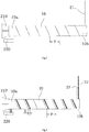
- Fig.1 is an illustrative view of a wire winding device according to an exemplary embodiment of the present invention
- Fig.3 is an illustrative view of a pipe 10 wound with a wire 20 according to an exemplary embodiment of the present invention.
- the wire winding device adapted to wind a wire 20 on a pipe 10.
- the wire winding device mainly comprises a wire supply mechanism 100, a pipe clamp 210, a first wire clamp 220, a rotation driver 200, and a linear drive mechanism 300.
- the wire supply mechanism 100 comprises an installation frame 110 and a wire spool 120 rotationally mounted on the installation frame 110 and coiled with the wire 20.
- the pipe clamp 210 is adapted to clamp one end 10a of the pipe 10.
- the first wire clamp 220 is fixed to the pipe clamp 210 and adapted to clamp an end of the wire 20.
- the rotation driver 200 is adapted to drive the pipe clamp 210 to rotate about a rotation axis R.
- the linear drive mechanism 300 is adapted to drive the pipe clamp 210 and the rotation driver 200 to linearly move in a first direction Y parallel to the rotation axis R.
- an output rotation speed of the rotation driver 200 and an output speed of the linear drive mechanism 300 are adjustable, so that a pitch P of the wire 20 wound on the pipe 10 is adjustable.
- Fig.4 is an illustrative view of a pipe wound with wires according to an exemplary embodiment of the present invention.
- the wire winding device is adapted to wind a plurality of different wires 21, 22 onto the pipe 10 at the same time.
- the wire 20 may comprise a first wire 21 and a second wire 22 different from the first wire 21.
- the wire winding device is adapted to wind the first wire 21 and the second wire 22 onto the pipe 10 at the same time.
- the wire supply mechanism 100 further comprises a wire separation device 130, which is adapted to separate a plurality of wires 21, 22 drawn from the wire spool 120, so as to ensure that a predetermined spacing D is defined between two adjacent wires 21, 22 wound on the pipe 10.
- the wire separation device 130 comprises a plurality of wire accommodation slots for accommodating the plurality of wires 21, 22, respectively.
- a spacing between two adjacent wire accommodation slots is equal to the predetermined spacing D.
- the pipe 10 is a glass pipe
- the wire 20 is a metal wire
- the wire winding device further comprises a flame burner 410, which is adapted to burn a local area of the pipe 10 corresponding to an end of the wire 20 wound on the pipe 10 until the local area of the pipe 10 is melt, so that the end of the wire 20 is bonded and fixed to the local area of the pipe 10.
- a flame burner 410 which is adapted to burn a local area of the pipe 10 corresponding to an end of the wire 20 wound on the pipe 10 until the local area of the pipe 10 is melt, so that the end of the wire 20 is bonded and fixed to the local area of the pipe 10.
- the wire winding device further comprises a translation mechanism 400, and the flame burner 410 is mounted on the translation mechanism 400.
- the translation mechanism 400 is adapted to move the flame burner 410 to the end of the wire 20 wound on the pipe 10. More specifically, the translation mechanism 400 is adapted to move the flame burner 410 to one end of the wire 20 near one end 10a of the pipe 10 and the other end of the wire 20 near the other end 10b of the pipe 10, so that two ends of the wire 20 are fixed to the pipe 10.
- the translation mechanism 400 is adapted to move the flame burner 410 in the first direction Y and a second direction X perpendicular to the first direction Y.
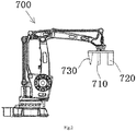
- Fig.2 is an illustrative view of a robot 700 according to an exemplary embodiment of the present invention.
- the wire winding device further comprises a robot 700 having a first gripper 710 adapted to grip the end of the wire 20.
- the robot 700 is adapted to place the end of the wire 20 gripped by the first gripper 710 on the first wire clamp 220 by moving the first gripper 710.
- the robot 700 further has a second gripper 720 adapted to grip the pipe 10, and the robot 700 is adapted to place the gripped pipe 10 onto or take the gripped pipe 10 away from the pipe clamp 210 by moving the second gripper 720.
- the robot 700 further comprises a cutter 730 adapted to cut off the wire 20, and the robot 700 is adapted to cut off the wire 20 by the cutter 730, so that the wire 20 wound on the pipe 10 is separated from the unwound wire 20.
- the wire winding device further comprises a second wire clamp 600 adapted to clamp a cutting end of the unwound wire 20.
- the robot 700 is adapted to grip the cutting end of the unwound wire 20 by the first gripper 710, and place the cutting end of the unwound wire 20 onto the second wire clamp 600 or take the cutting end away from the second wire clamp 600.
- the method mainly comprises steps of:
Landscapes
- Engineering & Computer Science (AREA)
- Power Engineering (AREA)
- Mechanical Engineering (AREA)
- Manufacturing & Machinery (AREA)
- Replacing, Conveying, And Pick-Finding For Filamentary Materials (AREA)
Applications Claiming Priority (1)
| Application Number | Priority Date | Filing Date | Title |
|---|---|---|---|
| CN201810288708.XA CN110340255A (zh) | 2018-04-03 | 2018-04-03 | 绕线装置和绕线方法 |
Publications (1)
| Publication Number | Publication Date |
|---|---|
| EP3553802A1 true EP3553802A1 (de) | 2019-10-16 |
Family
ID=66217672
Family Applications (1)
| Application Number | Title | Priority Date | Filing Date |
|---|---|---|---|
| EP19165369.0A Withdrawn EP3553802A1 (de) | 2018-04-03 | 2019-03-27 | Drahtwickelvorrichtung und verfahren zum wickeln von draht |
Country Status (2)
| Country | Link |
|---|---|
| EP (1) | EP3553802A1 (de) |
| CN (1) | CN110340255A (de) |
Cited By (4)
| Publication number | Priority date | Publication date | Assignee | Title |
|---|---|---|---|---|
| CN110600260A (zh) * | 2019-10-23 | 2019-12-20 | 温州市桑德拉自动化科技有限公司 | 一种全自动边滑式环形绕线机 |
| CN110695252A (zh) * | 2019-11-07 | 2020-01-17 | 南京思脉德医疗科技有限公司 | 医用栓塞弹簧多自由度自动绕线机 |
| CN113145770A (zh) * | 2021-03-22 | 2021-07-23 | 艾玛意自动化技术(南京)有限公司 | 一种液体循环管焊丝一体缠绕装置及缠绕方法 |
| CN120169843A (zh) * | 2025-05-21 | 2025-06-20 | 常州同泰高导新材料有限公司 | 一种铜杆夹持输送机构及连铸连轧生产线 |
Families Citing this family (4)
| Publication number | Priority date | Publication date | Assignee | Title |
|---|---|---|---|---|
| CN110718338B (zh) * | 2019-11-06 | 2021-01-29 | 珠海格力智能装备有限公司 | 绕线装置 |
| CN113928667B (zh) * | 2020-07-13 | 2023-05-12 | 泰科电子(上海)有限公司 | 线缆盘绕系统 |
| CN112605424A (zh) * | 2020-12-04 | 2021-04-06 | 南京纳特通信电子有限公司 | 一种电子器件加工工装和加工方法 |
| CN114235464B (zh) * | 2021-12-21 | 2023-11-17 | 无锡华工大光电智能科技有限公司 | 一种钢帘线取样机及钢帘线检测设备 |
Citations (4)
| Publication number | Priority date | Publication date | Assignee | Title |
|---|---|---|---|---|
| JP2002343238A (ja) * | 2001-05-21 | 2002-11-29 | Harison Toshiba Lighting Corp | 外部電極型蛍光ランプの製造方法 |
| JP2003086091A (ja) * | 2001-09-13 | 2003-03-20 | Harison Toshiba Lighting Corp | 管外周面への金属線捲装方法、外部電極型蛍光ランプの製造方法および管外周面への金属線捲装装置 |
| CN204679202U (zh) * | 2014-10-10 | 2015-09-30 | 北京交通大学 | 一种用于飞行器载人座舱的磁性液体微压差传感器 |
| CN104723574B (zh) * | 2015-03-30 | 2017-03-15 | 台州市黄岩双盛塑模有限公司 | 玻璃纤维复合材料弯管自动数控缠绕机 |
Family Cites Families (5)
| Publication number | Priority date | Publication date | Assignee | Title |
|---|---|---|---|---|
| CN101633452B (zh) * | 2008-07-24 | 2012-09-05 | 泰能机器工业有限公司 | 绕线装置 |
| CN102983689A (zh) * | 2012-11-16 | 2013-03-20 | 倪林木 | 斜绕式空心杯线圈绕线设备 |
| CN103606454B (zh) * | 2013-12-01 | 2015-09-30 | 浙江大学 | 一种单层扁平线圈的自动绕线机 |
| CN104240937B (zh) * | 2014-09-05 | 2017-02-01 | 深圳市有钢机电设备有限公司 | 绕线机及绕线方法 |
| CN105417276B (zh) * | 2015-12-21 | 2019-04-02 | 中山市三乐电子有限公司 | 双轴外绕绕线机 |
-
2018
- 2018-04-03 CN CN201810288708.XA patent/CN110340255A/zh active Pending
-
2019
- 2019-03-27 EP EP19165369.0A patent/EP3553802A1/de not_active Withdrawn
Patent Citations (4)
| Publication number | Priority date | Publication date | Assignee | Title |
|---|---|---|---|---|
| JP2002343238A (ja) * | 2001-05-21 | 2002-11-29 | Harison Toshiba Lighting Corp | 外部電極型蛍光ランプの製造方法 |
| JP2003086091A (ja) * | 2001-09-13 | 2003-03-20 | Harison Toshiba Lighting Corp | 管外周面への金属線捲装方法、外部電極型蛍光ランプの製造方法および管外周面への金属線捲装装置 |
| CN204679202U (zh) * | 2014-10-10 | 2015-09-30 | 北京交通大学 | 一种用于飞行器载人座舱的磁性液体微压差传感器 |
| CN104723574B (zh) * | 2015-03-30 | 2017-03-15 | 台州市黄岩双盛塑模有限公司 | 玻璃纤维复合材料弯管自动数控缠绕机 |
Cited By (4)
| Publication number | Priority date | Publication date | Assignee | Title |
|---|---|---|---|---|
| CN110600260A (zh) * | 2019-10-23 | 2019-12-20 | 温州市桑德拉自动化科技有限公司 | 一种全自动边滑式环形绕线机 |
| CN110695252A (zh) * | 2019-11-07 | 2020-01-17 | 南京思脉德医疗科技有限公司 | 医用栓塞弹簧多自由度自动绕线机 |
| CN113145770A (zh) * | 2021-03-22 | 2021-07-23 | 艾玛意自动化技术(南京)有限公司 | 一种液体循环管焊丝一体缠绕装置及缠绕方法 |
| CN120169843A (zh) * | 2025-05-21 | 2025-06-20 | 常州同泰高导新材料有限公司 | 一种铜杆夹持输送机构及连铸连轧生产线 |
Also Published As
| Publication number | Publication date |
|---|---|
| CN110340255A (zh) | 2019-10-18 |
Similar Documents
| Publication | Publication Date | Title |
|---|---|---|
| EP3553802A1 (de) | Drahtwickelvorrichtung und verfahren zum wickeln von draht | |
| WO2018172470A9 (en) | Heat shrinkable tube assembly system | |
| CN109950003A (zh) | 用于以粘性带全自动缠绕导线束的缠绕设备和方法 | |
| JP2018098176A (ja) | 自動配線処理システムおよび方法 | |
| CN113751619B (zh) | 一种挂线装置及记忆合金马达生产线 | |
| CN108573777A (zh) | 电线处理设备、电线处理方法和电线保持结构 | |
| JP2015224123A (ja) | テープ巻付装置及びテープ巻付方法 | |
| CN110060865B (zh) | 8字绕线系统及8字绕线方法 | |
| JP2008225016A5 (de) | ||
| CN103112758A (zh) | 成品电缆收卷装置 | |
| JP7626671B2 (ja) | ワイヤハーネスに対するテープ巻き付け装置 | |
| JP2003319522A (ja) | 電線切断皮剥装置および方法 | |
| US20180068786A1 (en) | Apparatus and method for manufacturing electronic component | |
| JP2017070135A (ja) | テープ巻付器およびテープ巻付方法 | |
| KR102541681B1 (ko) | 자동 테이핑장치 및 자동 테이핑방법 | |
| WO2017195599A1 (ja) | テープ巻付装置及びテープ巻付方法 | |
| CN113928667B (zh) | 线缆盘绕系统 | |
| JP2007030335A (ja) | スチールコード中継装置およびその使用方法 | |
| CN214541907U (zh) | 一种双线平行并绕绕线设备 | |
| CN113782336A (zh) | 一种旋转变压器定子下线工装以及采用该工装下线的方法 | |
| KR102461987B1 (ko) | 자동 테이프 와인더 반전 장치 | |
| JP7824146B2 (ja) | テープ巻き装置 | |
| JP2011182559A (ja) | ステータコイルの製造方法 | |
| US20250273937A1 (en) | Cable Aluminum Foil Layer Processing Device and Method | |
| JPH066917A (ja) | カセット式電線布線装置 |
Legal Events
| Date | Code | Title | Description |
|---|---|---|---|
| PUAI | Public reference made under article 153(3) epc to a published international application that has entered the european phase |
Free format text: ORIGINAL CODE: 0009012 |
|
| STAA | Information on the status of an ep patent application or granted ep patent |
Free format text: STATUS: THE APPLICATION HAS BEEN PUBLISHED |
|
| AK | Designated contracting states |
Kind code of ref document: A1 Designated state(s): AL AT BE BG CH CY CZ DE DK EE ES FI FR GB GR HR HU IE IS IT LI LT LU LV MC MK MT NL NO PL PT RO RS SE SI SK SM TR |
|
| AX | Request for extension of the european patent |
Extension state: BA ME |
|
| STAA | Information on the status of an ep patent application or granted ep patent |
Free format text: STATUS: REQUEST FOR EXAMINATION WAS MADE |
|
| 17P | Request for examination filed |
Effective date: 20200325 |
|
| RBV | Designated contracting states (corrected) |
Designated state(s): AL AT BE BG CH CY CZ DE DK EE ES FI FR GB GR HR HU IE IS IT LI LT LU LV MC MK MT NL NO PL PT RO RS SE SI SK SM TR |
|
| STAA | Information on the status of an ep patent application or granted ep patent |
Free format text: STATUS: EXAMINATION IS IN PROGRESS |
|
| 17Q | First examination report despatched |
Effective date: 20200820 |
|
| STAA | Information on the status of an ep patent application or granted ep patent |
Free format text: STATUS: THE APPLICATION IS DEEMED TO BE WITHDRAWN |
|
| 18D | Application deemed to be withdrawn |
Effective date: 20230404 |