EP3553599B1 - Membranvorrichtung, objektivtubus und bildgebungsvorrichtung oder projektionsvorrichtung - Google Patents
Membranvorrichtung, objektivtubus und bildgebungsvorrichtung oder projektionsvorrichtung Download PDFInfo
- Publication number
- EP3553599B1 EP3553599B1 EP17878729.7A EP17878729A EP3553599B1 EP 3553599 B1 EP3553599 B1 EP 3553599B1 EP 17878729 A EP17878729 A EP 17878729A EP 3553599 B1 EP3553599 B1 EP 3553599B1
- Authority
- EP
- European Patent Office
- Prior art keywords
- diaphragm
- blade
- hole
- cam groove
- fixing boss
- Prior art date
- Legal status (The legal status is an assumption and is not a legal conclusion. Google has not performed a legal analysis and makes no representation as to the accuracy of the status listed.)
- Active
Links
Images


Classifications
-
- G—PHYSICS
- G03—PHOTOGRAPHY; CINEMATOGRAPHY; ANALOGOUS TECHNIQUES USING WAVES OTHER THAN OPTICAL WAVES; ELECTROGRAPHY; HOLOGRAPHY
- G03B—APPARATUS OR ARRANGEMENTS FOR TAKING PHOTOGRAPHS OR FOR PROJECTING OR VIEWING THEM; APPARATUS OR ARRANGEMENTS EMPLOYING ANALOGOUS TECHNIQUES USING WAVES OTHER THAN OPTICAL WAVES; ACCESSORIES THEREFOR
- G03B9/00—Exposure-making shutters; Diaphragms
- G03B9/02—Diaphragms
- G03B9/06—Two or more co-operating pivoted blades, e.g. iris type
-
- G—PHYSICS
- G03—PHOTOGRAPHY; CINEMATOGRAPHY; ANALOGOUS TECHNIQUES USING WAVES OTHER THAN OPTICAL WAVES; ELECTROGRAPHY; HOLOGRAPHY
- G03B—APPARATUS OR ARRANGEMENTS FOR TAKING PHOTOGRAPHS OR FOR PROJECTING OR VIEWING THEM; APPARATUS OR ARRANGEMENTS EMPLOYING ANALOGOUS TECHNIQUES USING WAVES OTHER THAN OPTICAL WAVES; ACCESSORIES THEREFOR
- G03B7/00—Control of exposure by setting shutters, diaphragms or filters, separately or conjointly
- G03B7/08—Control effected solely on the basis of the response, to the intensity of the light received by the camera, of a built-in light-sensitive device
- G03B7/12—Control effected solely on the basis of the response, to the intensity of the light received by the camera, of a built-in light-sensitive device a hand-actuated member moved from one position to another providing the energy to move the setting member, e.g. depression of shutter release button causes a stepped feeler to co-operate with the pointer of the light-sensitive device to set the diaphragm and thereafter release the shutter
-
- G—PHYSICS
- G03—PHOTOGRAPHY; CINEMATOGRAPHY; ANALOGOUS TECHNIQUES USING WAVES OTHER THAN OPTICAL WAVES; ELECTROGRAPHY; HOLOGRAPHY
- G03B—APPARATUS OR ARRANGEMENTS FOR TAKING PHOTOGRAPHS OR FOR PROJECTING OR VIEWING THEM; APPARATUS OR ARRANGEMENTS EMPLOYING ANALOGOUS TECHNIQUES USING WAVES OTHER THAN OPTICAL WAVES; ACCESSORIES THEREFOR
- G03B17/00—Details of cameras or camera bodies; Accessories therefor
- G03B17/02—Bodies
Definitions
- the present invention relates to an optical diaphragm device, a lens barrel and an imaging device or a projection device.
- an optical diaphragm device is used for adjusting an amount of light from an imaging object which is incident on an imaging plane.
- the optical diaphragm device includes a circular ring-like housing body.
- an aperture diameter of a diaphragm aperture becomes maximum (fully open)
- a diaphragm blade is retracted within a width of the housing body. Accordingly, with respect to a width of the housing body, it is necessary to ensure at least a width equal to or more than a width of the diaphragm blade as a retraction space for the diaphragm blade.
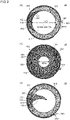
- Fig. 10(a) to Fig. 10(d) are plan views for describing a conventional optical diaphragm device 900.
- Fig. 10(a) is a plan view of the optical diaphragm device 900 as viewed in a plan view along an optical axis OA.
- Fig. 10(a) only a state where light leakage prevention blades 920 protrude is shown, and the illustration of diaphragm blades 910 is omitted.
- Fig. 10(b) is a plan view showing the diaphragm blade 910
- Fig. 10(c) is a plan view showing the light leakage prevention blade 920
- Fig. 10(d) is a plan view showing a housing body 940.
- the conventional optical diaphragm device 900 is an optical diaphragm device 900 for changing an aperture diameter of a diaphragm aperture by advancing or retracting a plurality of blades with respect to the optical axis OA.
- the optical diaphragm device 900 includes: a plurality of diaphragm blades 910 each having a diaphragm blade body 911, a diaphragm blade fixing boss 912 protruding from one surface of the diaphragm blade body 911 toward a side in a first direction along the optical axis OA, and a diaphragm blade moving boss 913 protruding from the other surface of the diaphragm blade body 911 toward a side in a second direction opposite to the first direction; a plurality of light leakage prevention blades 920 each forming a pair with each of the above-mentioned diaphragm blades 910, each light leakage prevention blade 920 having a light leakage prevention blade body 921, a light leakage prevention blade fixing boss 922 protruding from one surface of the light leakage prevention blade body 921 toward the side in the first direction, and a light leakage prevention blade moving boss 923 protruding from the other surface of the light leakage prevention blade
- the optical diaphragm device 900 includes a plurality of pairs each consisting of the diaphragm blade 910 and the light leakage prevention blade 920 (six pairs in the conventional optical diaphragm device 900 shown in Fig. 10 ).
- the cam grooves 933 are formed in the drive ring 930.
- the number of cam grooves 933 corresponds to the number of pairs each consisting of the diaphragm blade 910 and the light leakage prevention blade 920.
- a plurality of pairs each consisting of a first hole 941j and a second hole 942j are formed in the housing body 940 corresponding to the plurality of pairs each consisting of the diaphragm blade 910 and the light leakage prevention blade 920.
- the number of pairs each consisting of the first hole 941j and the second hole 942j corresponds to the number of pairs each consisting of the diaphragm blade and the light leakage prevention blade.
- the diaphragm blade fixing boss 912 and the light leakage prevention blade fixing boss 922 are inserted into the pair of the first hole 941j and the second hole 942j respectively.
- the diaphragm blade moving boss 913 and the light leakage prevention blade moving boss 923 are respectively inserted into one cam groove 933 (j: an integer of 1 or more).
- the light leakage prevention blades 920 can be added while using the existing basic structure for driving the diaphragm blades (the housing body, the drive ring and the like) without modification and hence, leakage of light brought about by narrowing of a width of the diaphragm blade can be prevented.
- Patent literature 2 discloses an optical diaphragm device comprising a plurality of blades (5) and blade (6).
- a cam groove (6b) is formed in the blade (6), and a moving boss (5b) formed in the blade (5) is inserted into the cam groove (6b).
- the conventional optical diaphragm device 900 adopts the structure where the diaphragm blade moving boss 913 and the light leakage prevention blade moving boss 923 are respectively inserted into one cam groove 933.
- two kinds of blades (the diaphragm blade 910 and the light leakage prevention blade 920) are driven by one cam groove 933. Accordingly, as a length of the cam groove 933, a length for driving the light leakage prevention blade 920 also becomes necessary in addition to a length for driving the diaphragm blade 910.
- the cam groove 933 is formed of a groove portion for driving the diaphragm blade 910 and a groove portion for driving the light leakage prevention blade 920. Accordingly, the cam groove 933 becomes necessary where the cam groove 933 has a long total length compared to the configuration where the cam groove 933 is formed of only the groove for driving only either one of the blades.
- the first holes 941j and the second holes 942j are disposed at the positions which are at the same distance from the optical axis OA (the position being away from the optical axis OA by a distance R 9 ).
- the first holes 941j and the second holes 942j are disposed along the same circumference C. That is, the diaphragm blade fixing bosses 912 and the light leakage prevention blade fixing bosses 922 which are respectively inserted into the first holes 941j and the second holes 942j are disposed at the positions which are at the same distance from the optical axis OA (disposed along the same circumference C).
- the diaphragm blade fixing bosses 912 and the light leakage prevention blade fixing bosses 922 are disposed along the same circumference C. Accordingly, it is necessary to keep a required distance between the diaphragm blade fixing boss 912 and the light leakage prevention blade fixing boss 922. Accordingly, there exist many restrictive conditions in increasing the arrangement number of the diaphragm blade fixing bosses 912 and hence, it is difficult to increase the number of the diaphragm blades 910.
- the shape closer to a circle than an angular shape is preferable from a viewpoint of improving quality of imaging, and the shape of the diaphragm aperture can be made as close as possible to a circle by increasing the number of diaphragm blades. Accordingly, it is desirable to increase the number of diaphragm blades from a viewpoint of improving quality of imaging.
- the present invention has been made in view of the above-mentioned circumstances, and it is an object of the present invention to provide an optical diaphragm device where the number of diaphragm blades can be easily increased.
- An optical diaphragm device is an optical diaphragm device capable of changing an aperture diameter of a diaphragm aperture by advancing or retracting a plurality of blades with respect to an optical axis, the optical diaphragm device comprising:
- the second cam groove is further formed in the light leakage prevention blade, the moving boss of the diaphragm blade is inserted into the second cam groove of the light leakage prevention blade and the first cam groove of the drive ring. Accordingly, when the drive ring is rotated, a force acts on the moving boss of the diaphragm blade through the first cam groove of the drive ring, and the first blade portion of the diaphragm blade is rotated using the first fixing boss as a fulcrum (rotary shaft).
- a length of the first cam groove can be set shorter than a length of a cam groove in a conventional optical diaphragm device by an amount that the formation of the cam groove pattern becomes unnecessary. Since the length of the first cam groove can be shortened, the number of first cam grooves formed on the drive ring can be easily increased.
- the set of the first fixing boss and the first hole is disposed at the position which differs from the position where the set of the second fixing boss and the second hole is positioned with respect to a distance from the optical axis. Accordingly, the circumference on which the set of the first fixing boss and the first hole is disposed and the circumference on which the set of the second fixing boss and the second hole is disposed differ from each other with respect to the distance from the optical axis. Accordingly, it is possible to easily increase the number of pairs each consisting of the set of the first fixing boss and the first hole and the set of the second fixing boss and the second hole. As a result, it is possible to easily increase the number of diaphragm blades.
- the optical diaphragm device of the present invention it is possible to provide the optical diaphragm device where the number of diaphragm blades can be easily increased.
- the set of the first fixing boss and the first hole be disposed at a position where the distance from the optical axis to the set of the first fixing boss and the first hole is shorter than the distance from the optical axis to the set of the second fixing boss and the second hole.
- the position where the set of the first fixing boss and the first hole is disposed is the position where the rotary shaft of the diaphragm blade is disposed.
- an attention is focused on a rotation angle of the diaphragm blade which rotates between a position in a state where the aperture diameter of the diaphragm aperture is maximized (fully open state) and a position in a state where the aperture diameter of the diaphragm aperture is minimized (minimum aperture state).
- the nearer the rotary shaft of the diaphragm blade is disposed to the optical axis the larger the rotation angle becomes.
- driving of the diaphragm blade is minimally affected by irregularities in manufacture in positions, sizes or the like of the first fixing boss, the first hole, the moving boss, the first cam groove of the drive ring and the like.
- the length of the diaphragm blade can be decreased by arranging the rotary shaft of the diaphragm blade closer to the optical axis (by arranging the set of the first fixing boss and the first hole at the position closer to the optical axis than the position of the set of the second fixing boss and the second hole).
- inertia of the diaphragm blade during rotation can be decreased and hence, accuracy of rotation and velocity of rotation can be enhanced.
- Downsizing of the optical diaphragm device can be also realized.
- the set of the first fixing boss and the first hole and the set of the second fixing boss and the second hole be arranged on a same straight line extending in a radial direction from the optical axis.
- an angle which the set of the first fixing boss and the first hole and the set of the second fixing boss and the second hole which form a pair occupy (an angle made by a line which connects the set of the first fixing boss and the first hole with the optical axis and a line which connects the set of the second fixing boss and the second hole with the optical axis) can be minimized (o degrees).
- the occupied angle can be minimized and hence, it is possible to arrange the larger number of pairs each consisting of the set of the first fixing boss and the first hole and the set of the second fixing boss and the second hole around the optical axis whereby the degree of freedom in designing the optical diaphragm device can be enhanced.
- the optical diaphragm device which enables easy working (drilling) and inspection of the optical diaphragm device.
- the first holes and the second holes are formed in the housing body by working with reference to the optical axis
- the first holes are formed by working and, thereafter, the second holes are formed by working by changing only a distance in a radial direction without changing an angle with respect to the optical axis. Accordingly, working can be continued without performing a step of changing an angle. Substantially the same manner of operation and advantageous effects can be acquired also in the inspection of the optical diaphragm device.
- a recessed portion be formed by cutting away such that when the diaphragm blade is moved to a position where the aperture diameter of the diaphragm aperture becomes maximum, the moving boss with respect to the diaphragm blade and the light leakage prevention blade which form another pair is disposed inside the recessed portion.
- the first cam groove be formed at an angle inclined in a direction away from the optical axis as the first cam groove extends in the diaphragm rotational direction with respect to the circumferential direction about the optical axis.
- the first cam groove having such inclination when the drive ring is rotated in the diaphragm rotational direction, the position of the moving boss inserted into the first cam groove formed in the drive ring is moved in the direction toward the optical axis.
- a length of the first cam groove can be decreased compared to the configuration where the inclination direction of the first cam groove is reversed.
- an angle of the second cam groove with respect to the circumferential direction be set large compared to an angle of the first cam groove with respect to the circumferential direction.
- the second cam groove is formed with a relatively large (deep) angle with respect to the circumferential direction (compared to an angle of the first cam groove with respect to the circumferential direction).
- a lens barrel according to the present invention is characterized in that the optical diaphragm device described in any one of the above-mentioned [1] to [6] and a lens are housed in the lens barrel.
- An imaging device or a projection device is characterized in that the imaging device or the projection device includes the optical diaphragm device described in any one of the above-mentioned [1] to [6] or the lens barrel described in the above-mentioned [7].
- Fig. 1 to Fig. 2 are views for describing an optical diaphragm device 10 according to the embodiment 1.
- Fig. i(a) is a perspective view showing a state where the optical diaphragm device 10 is disassembled.
- Fig. i(b) is a perspective view of the optical diaphragm device 10 in an assembled state.
- Fig. 2 is a plan view of the optical diaphragm device 10 as viewed in a plan view along an optical axis OA.
- Fig. 2(a) shows a state where a diaphragm blade 100 and a light leakage prevention blade 200 are retracted within a width (a width in a direction orthogonal to the optical axis OA) of a housing body 400.
- Fig. i(a) is a perspective view showing a state where the optical diaphragm device 10 is disassembled.
- Fig. i(b) is a perspective view of the optical diaphragm device
- FIG. 2(a) shows a state where an aperture diameter of a diaphragm aperture (an aperture formed by the diaphragm blades 100) is set to a maximum value (fully open state).
- Fig. 2(c) is a view showing a minimum aperture state where the aperture diameter of the diaphragm aperture is set to a minimum value.
- Fig. 2(b) is a view showing an intermediate aperture state where the diaphragm blades 100 and the light leakage prevention blades 200 are moved to a position between the fully open state and the minimum aperture state.
- a cover 500 is mounted on the housing body 400 for preventing the removal of a drive ring 300.
- the optical diaphragm device 10 has a circular ring shape having an aperture 413 as viewed in a plan view along the optical axis OA.
- An aperture diameter AD of the diaphragm aperture is changed by protruding a plurality of blades (diaphragm blades 100 in this embodiment) toward the inside of the aperture 413 (toward the optical axis OA).
- An amount of light which passes through the diaphragm aperture is adjusted by changing the aperture diameter AD of the diaphragm aperture.
- the optical diaphragm device 10 includes the diaphragm blades 100, the light leakage prevention blades 200, the drive ring 300, and the housing body 400.
- the housing body 400 as a receiving tray, the plurality of diaphragm blades 100 and the plurality of light leakage prevention blades 200 are stacked on the housing body 400 in an overlapping manner, and the drive ring 300 is placed on the diaphragm blades 100 and the light leakage prevention blades 200. Further, the cover 500 is placed on the drive ring 300.
- the aperture diameter AD of the diaphragm is changed in a transcending manner from an aperture diameter ADf to an aperture diameter ADm and, then, from the aperture diameter ADm to the aperture diameter in a minimum aperture state corresponding to a protruding amount of the diaphragm blades 100 toward the inside of the aperture 413.
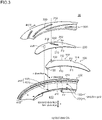
- Fig. 3 is a view for describing a main part of the optical diaphragm device 10 according to the embodiment 1.
- Fig. 3 is a perspective view of the diaphragm blade 100 and the light leakage prevention blade 200 which form a pair, and portions of the drive ring 300 and the housing body 400 which correspond to the diaphragm blade 100 and the light leakage prevention blade 200 by spotlighting these constitutional elements. Other constitutional elements are omitted from the drawing.
- Symbol 112 indicates an outer peripheral edge of a first blade portion 110
- symbol 212 indicates an outer peripheral edge of a second blade portion 210.
- the diaphragm blade 100 has: the first blade portion 110 which is formed of a first planar plate 102, protrudes toward the inside of the aperture 413 thus forming a diaphragm aperture, and shields light incident on the diaphragm aperture of the optical diaphragm device 10 (also see Fig. 2(a) to Fig. 2(c) ); a first fixing boss 120 which protrudes from one surface F1 of the first planar plate 102 toward a side in a first direction along the optical axis OA; and a moving boss 130 which protrudes from the other surface F2 of the first planar plate 102 toward a side in a second direction opposite to the first direction.
- the first planar plate 102 has light shielding property, and is made of a material which allows the first planar plate 102 to mate with and to smoothly slide on other constitutional elements (the light leakage prevention blade 200, the housing body 400 and the like).
- the first fixing boss 120 and the moving boss 130 have a circular cylindrical shape and have a fixed radius respectively.
- the first fixing boss 120 is inserted into a first hole 401j formed in the housing body 400 in a revolvable manner. That is, the position where the set of the first fixing boss 120 and the first hole 401j is disposed is the position where the rotary shaft of the diaphragm blade 100 is disposed. "Fixing" of the first fixing boss 120 means that the position of the boss with respect to the housing body is not moved and is fixed, and the first fixing boss 120 per se is revolvable.
- the light leakage prevention blade 200 has: a second blade portion 210 which is formed of a second planar plate 202 and shields light through light leaking portions other than the diaphragm aperture of the optical diaphragm device 10(also see Fig. 2(c) ); and a second fixing boss 220 which protrudes from one surface F 3 of the second planar plate 202 toward the side in the first direction.
- a light leakage prevention blade 200 forms a pair with the above-mentioned diaphragm blade 100.
- the second planar plate 202 is made of a material which allows the second planar plate 202 to mate with and to smoothly slide on other constitutional elements (the diaphragm blade 100, the housing body 400 and the like).
- the second fixing boss 220 has a circular cylindrical shape and having a fixed radius.
- the second fixing boss 220 is inserted into a second hole 402j formed in the housing body 400 in a revolvable manner. That is, the position where the second fixing boss 220 and the second hole 402j are disposed is the position where the rotary shaft of the light leakage prevention blade 200 is disposed. "fixing" of the second fixing boss 220 means that the position of the boss with respect to the housing body is not moved and is fixed, and the second fixing boss 220 per se is revolvable.
- the drive ring 300 is a ring-like planar plate which has a circular opening on an inner side.
- the moving boss 130 is inserted into the first cam groove 330.
- the first cam groove 300 is formed such that a distance between the first cam groove 330 and the optical axis OA differs corresponding to a position of the cam groove.
- the first cam groove 330 may partially have a zone where the distance between the first cam groove 330 and the optical axis OA is equal when the cam groove is viewed along a circumferential direction.
- the first cam groove 330 is moved in the circumferential direction about the optical axis OA.
- the moving boss 130 inserted into the first cam groove 330 is rotated about the first fixing boss 120 inserted into the first hole 401j. That is, the moving boss 130 is moved in a direction toward the inside of the aperture 413 (hereinafter referred to as -r direction) or in a direction toward the outside of the aperture 413 (hereinafter referred to as r direction) using the first fixing boss 120 as the center of rotation corresponding to a direction that the drive ring 300 is rotated.
- a rotary lever 340 which integrally rotates with a drive ring body 310 is formed on the drive ring 300, and a force is applied to the rotary lever 340 by a rotational force applying unit not shown in the drawing.
- the housing body 400 has a circular ring shape as an overall shape, and has the aperture 413 in the inside thereof. As described previously, the housing body 400 accommodates the diaphragm blades 100, the light leakage prevention blades 200, and the drive ring 300.
- n sets each consisting of the first hole 401j and the second hole 402j (n being the number of pairs each consisting of the diaphragm blade 100 and the light leakage prevention blade 200)(n: an integer of 2 or more) are formed in the housing body 400.
- the first hole 401j and the second hole 402j are formed corresponding to the above-mentioned diaphragm blade 100 and the light leakage prevention blade 200 which form a pair.
- the first fixing boss 120 and the second fixing boss 220 are inserted into the pair of first hole 401j and the second hole 402j respectively.
- the housing body 400 has a notched portion 411.
- the notched portion 411 is formed by cutting away a portion of an outer peripheral wall 410 so as to allow the rotation of the rotary lever 340 of the drive ring 300.
- the optical diaphragm device 10 has n sets (a plurality of pairs) each consisting of the diaphragm blade 100 and the light leakage prevention blade 200. n pieces (a plurality of) first cam grooves 330 are formed in the drive ring 300 such that the first cam grooves 330 respectively correspond to the moving bosses 130 formed on the respective diaphragm blades 100.
- the optical diaphragm device 10 has 11 sets each consisting of the diaphragm blade 100 and the light leakage prevention blade 200 as shown in Fig. 1 to Fig. 3 .
- the diaphragm blade 100 and the light leakage prevention blade 200 which form a pair are stacked on the housing body 400 toward a second direction in order of the diaphragm blade 100 and the light leakage prevention blade 200.
- a second cam groove 230 is formed in the light leakage prevention blade 200.
- the second cam groove 230 is disposed at the position which corresponds to the moving boss 130.
- the moving boss 130 of the diaphragm blade 100 is inserted into the second cam groove 230 of the light leakage prevention blade 200, and is also inserted into the first cam groove 330 of the drive ring 300.
- the moving boss 130 may not be inserted into the first cam groove 330 over a full depth (a thickness of the drive ring 300), or may penetrate the first cam groove 330 in addition to the second cam groove 230.
- the moving boss 130 is in a state where the moving boss 130 substantially penetrates the first cam groove 330.
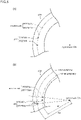
- Fig. 4 is a plan view for describing a positional relationship between the first fixing boss 120, the second fixing boss 220, the moving boss 130, the first cam groove 330, the second cam groove 230 and the like in the optical diaphragm device 10 according to the embodiment 1.
- Fig. 4(a) shows the diaphragm blade 100 and the light leakage prevention blade 200 which form a pair, and the first cam groove 330 and the second cam groove 230 which correspond to these blades 100, 200.
- Fig. 4 also shows the diaphragm blade 100' out of the diaphragm blade and the light leakage prevention blade which form another pair and the moving boss 130' corresponding to the diaphragm blade 100'.
- Fig. 4(b) shows a mode where a plurality of pairs each consisting of the first hole 401j and the second hole 402j (j: an integer of 1 or more) into which the first fixing boss 120 and the second fixing boss 220 are inserted are formed in the housing body 400. Other constitutional elements are omitted from the drawing.
- the first fixing boss 120 and the second fixing boss 220 are disposed at positions which differ from each other in distance from the optical axis OA.
- the first fixing boss 120 and the second fixing boss 220 are disposed in a displaced manner toward an inner peripheral side and an outer peripheral side respectively (also see Fig. 3 and the like).
- the first hole 401j and the second hole 402j which form a pair and into which the first fixing boss 120 and the second fixing boss 220 are inserted are disposed at positions which differ from each other in distance from the optical axis OA.
- Fig. 4(a) shows the example where the first fixing boss 120 is disposed on an inner peripheral side.
- the optical diaphragm device 10 of the embodiment 1 is not limited to such an example. That is, the second fixing boss 220 may be disposed on an inner peripheral side of the first fixing boss 120.
- the optical diaphragm device 10 is an optical diaphragm device which changes an aperture diameter of the diaphragm aperture by advancing or retracting the plurality of blades with respect to the optical axis, and the optical diaphragm device 10 includes: the diaphragm blades 100; the light leakage prevention blades 200 each forms a pair with each corresponding diaphragm blade 100; the drive ring 300; and the housing body 400.
- the diaphragm blade 100 has: the first blade portion 110 which is formed of the first planar plate 102 and shields light incident on the diaphragm aperture (aperture formed by the diaphragm blades 100) of the optical diaphragm device 10; the first fixing boss 120 which protrudes from one surface F1 of the first planar plate 102 toward the side in the first direction along the optical axis OA; and the moving boss 130 which protrudes from the other surface F2 of the first planar plate 102 toward the side in the second direction opposite to the first direction.
- the light leakage prevention blade 200 has: the second blade portion 210 which is formed of the second planar plate 202 and shields light through light leaking portions other than the diaphragm aperture of the optical diaphragm device 10; and the second fixing boss 220 which protrudes from one surface F 3 of the second planar plate 202 toward the side in the first direction.
- the drive ring 300 has the first cam grooves 330 into which the moving bosses 130 are inserted. With respect to the first cam groove 330, a distance between the first cam groove 330 and the optical axis OA differs corresponding to the position of the cam groove.
- the drive ring 300 is rotatable about the optical axis OA. Accordingly, when the drive ring 300 is rotated about the optical axis OA, the first cam grooves 330 are moved in a circumferential direction. Accordingly, the moving bosses 130 inserted into the first cam grooves 330 are moved in an r direction or a -r direction.
- the housing body 400 accommodates the diaphragm blades 100, the light leakage prevention blades 200 and the drive ring 300.
- the optical diaphragm device 10 includes n sets (a plurality of pairs) each consisting of the diaphragm blade 100 and the light leakage prevention blade 200. n pieces of (a plurality of) first cam grooves 330 are formed in the drive ring 300 respectively corresponding to the moving bosses 130 formed on the respective diaphragm blades 100.
- n sets each consisting of the first hole 401j and the second hole 402j (n being the number of pairs each consisting of the diaphragm blade 100 and the light leakage prevention blade 200) are formed in the housing body 400.
- the first fixing boss 120 and the second fixing boss 220 are respectively inserted into each pair consisting of the first hole 401j and the second hole 402j corresponding to the diaphragm blade 100 and the light leakage prevention blade 200 which form a pair.
- the second cam groove 230 is formed in the light leakage prevention blade 200, and the moving boss 130 of the diaphragm blade 100 is inserted into the second cam groove 230 of the light leakage prevention blade 200 and is inserted into the first cam groove 330 of the drive ring 300.
- the second cam groove 230 is further formed in the light leakage prevention blade 200.
- the moving boss 130 of the diaphragm blade 100 is inserted into the second cam groove 230 of the light leakage prevention blade 200 and is inserted into the first cam groove 330 of the drive ring 300.
- the light leakage prevention blade 200 can be also driven in an interlocking manner with driving of the diaphragm blade 100.
- the length of the first cam groove 330 can be made shorter than the length of the cam groove in the conventional optical diaphragm device. In this manner, the length of the first cam groove 330 can be shortened and hence, the number of first cam grooves 330 which can be formed in the drive ring 300 can be easily increased. Because of such an advantageous effect, the number of diaphragm blades 100 can be also easily increased. The number of light leakage prevention blades 200 each forms a pair with the corresponding diaphragm blade 100 can be also easily increased.
- the set of the first fixing boss 120 and the first hole 401j is disposed at the position which differs from the position where the set of the second fixing boss 220 and the second hole 402j is positioned with respect to a distance from the optical axis OA. Accordingly, the plurality of sets of the first fixing boss 120 and the first hole 401j and the plurality of sets of the second fixing boss 220 and the second hole 402j are respectively formed on respective circumferences which differ from each other in distance from the optical axis OA.
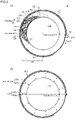
- Fig. 5 is a plan view for describing an advantageous effect acquired by the optical diaphragm device 10 according to the embodiment 1.
- Fig. 5(a) is a view which corresponds to the conventional optical diaphragm device 900
- Fig. 5(b) is a view which corresponds to the optical diaphragm device 10 according to the embodiment 1.
- Fig. 5(a) and Fig. 5(b) only a part of the housing body 400 is shown.
- Fig. 5(a) shows the arrangement relationship between the set of the diaphragm blade fixing boss 912 and the first hole 941j (j: an integer of 1 or more) and the set of the light leakage prevention blade fixing boss 922 and the second hole 942j (j: an integer of 1 or more).
- Fig. 5(b) shows the arrangement relationship between the set of the first fixing boss 120 and the first hole 401j (j: an integer of 1 or more) and the set of the second fixing boss 220 and the second hole 402j (j: an integer of 1 or more).
- Other constitutional elements are not shown in the drawing.
- the set of the diaphragm blade fixing boss 912 and the first hole 941j and the set of the light leakage prevention blade fixing boss 922 and the second hole 942j are disposed at the same position in distance from the optical axis OA. That is, the set of the diaphragm blade fixing boss 912 and the first hole 941j and the set of the light leakage prevention blade fixing boss 922 and the second hole 942j are disposed on the same circumference.
- the set of the first fixing boss 120 and the first hole 401j and the set of the second fixing boss 220 and the second hole 402j are disposed at positions which differ from each other in distance from the optical axis OA.
- the set of the first fixing boss 120 and the first hole 401j and the set of the second fixing boss 220 and the second hole 402j are disposed in a displaced manner toward an inner peripheral side and toward an outer peripheral side.
- the degree of freedom in designing is increased and hence, the number of pairs each consisting of the set of the first fixing boss 120 and the first hole 401j and the set of the second fixing boss 220 and the second hole 402j can be easily increased. As a result, the number of diaphragm blades 100 is easily increased.
- the number of first cam grooves, the number of first fixing bosses and the first holes and the like can be easily increased and hence, it is possible to provide the diaphragm device where the number of diaphragm blades can be easily increased.
- the set of the first fixing boss 120 and the first hole 401j is disposed at the position where the distance between the set of the first fixing boss 120 and the first hole 401j and the optical axis OA is shorter than the distance between the set of the second fixing boss 220 and the second hole 402j and the optical axis OA. That is, the set of the first fixing boss 120 and the first hole 401j is disposed on an inner peripheral side of the set of the second fixing boss 220 and the second hole 402j.
- the position where the set of the first fixing boss 120 and the first hole 401j is disposed is, in other words, the position where the rotary shaft of the diaphragm blade 100 is disposed.
- a rotation angle of the diaphragm blade 100 which rotates between a position in a state where the aperture diameter AD of the diaphragm aperture is maximized (fully open state) and a position in a state where the aperture diameter AD of the diaphragm aperture is minimized (minimum aperture state).
- the nearer the rotary shaft of the diaphragm blade 100 is disposed to the optical axis OA the larger the rotation angle becomes.
- the diaphragm aperture with high accuracy as a whole by arranging the set of the first fixing boss 120 and the first hole 401j at a position where the distance from the optical axis OA to the set of the first fixing boss 120 and the first hole 401j is shorter than the distance from the optical axis OA to the set of the second fixing boss 220 and the second hole 402j, that is, by arranging the rotary shaft of the diaphragm blade 100 at the position closer to the optical axis OA.
- the length of the diaphragm blade 100 can be decreased by arranging the rotary shaft of the diaphragm blade 100 closer to the optical axis OA (by arranging the set of the first fixing boss 120 and the first hole 401j at the position closer to the optical axis OA than the position of the set of the second fixing boss 220 and the second hole 402j).
- the length of the diaphragm blade 100 By decreasing the length of the diaphragm blade 100, inertia of the diaphragm blade 100 during rotation can be decreased and hence, accuracy of rotation and velocity can be enhanced. Downsizing of the optical diaphragm device 10 can be also realized.
- the set of the first fixing boss 120 and the first hole 401j, and the set of the second fixing boss 220 and the second hole 402j are arranged on the same straight line extending in a radial direction (r direction) from the optical axis OA. That is, the optical axis OA, the set of the first fixing boss 120 and the first hole 401j, and the set of the second fixing boss 220 and the second hole 402j are arranged on the same straight line.
- an angle which the set of the first fixing boss and the first hole 401j and the set of the second fixing boss and the second hole 402j which form a pair occupy (an angle made by a line which connects the set of the first fixing boss and the first hole 401j with the optical axis OA and a line which connects the set of the second fixing boss and the second hole 402j with the optical axis OA) can be minimized. That is, such an occupied angle can be set to 0°
- the occupied angle can be minimized and hence, it is possible to arrange the larger number of pairs each consisting of the set of the first fixing boss 120 and the first hole 401j and the set of the second fixing boss 220 and the second hole 402j around the optical axis OA whereby the degree of freedom in designing the optical diaphragm device can be enhanced.
- the optical diaphragm device which enables easy working (drilling) and inspection of the optical diaphragm device 10.
- the first holes 401j and the second holes 401j are formed in the housing body 400 by working with reference to the optical axis OA
- the first holes 401j are formed by working and, thereafter, the second holes 402j are formed by working while changing a distance only in a radial direction without changing an angle with respect to the optical axis OA. Accordingly, working can be continued without performing a step of changing an angle. Substantially the same manner of operation and advantageous effects can be acquired also in the inspection of the optical diaphragm device.
- a recessed portion 114 is formed on an outer peripheral edge 112 of the diaphragm blade 100.
- the recessed portion 114 is formed so as to allow the moving boss 130' relating to the diaphragm blade 100' (see double-dashed chain line in Fig. 4 (a) ) and a light leakage prevention blade (not shown in the drawing) which form another pair to be disposed in the recessed portion 114 when the diaphragm blade 100 is moved to the position where the aperture diameter of the diaphragm aperture becomes maximum.
- a width of the diaphragm blade 100 is decided depending on designing of the optical diaphragm device.
- the outer peripheral edge 112 of the diaphragm blade 100 interferes with the moving boss relating to the diaphragm blade and the light leakage prevention blade which form another pair which is the neighboring pair in a plan-view layout.
- a design may be considered where the moving boss is disposed at the position which is further shifted in a radial direction(r direction) so as to move the moving boss away from the outer peripheral edge 112.
- the optical diaphragm device becomes large-sized by an amount that the moving boss is shifted.
- the recessed portion 114 is formed on the outer peripheral edge 112 of the diaphragm blade 100. Accordingly, it is possible to avoid the interference between the diaphragm blade 100 out of the diaphragm blade 100 and the light leakage prevention blade 200 which form a pair with the moving boss 130' relating to the diaphragm blade 100' and the light leakage prevention blade (not shown in drawing) which form another pair. As a result, large-sizing of the optical diaphragm device can be suppressed.
- the first cam groove 330 is formed at an angle which is inclined in a direction away from the optical axis OA toward a diaphragm rotational direction ROT with respect to a circumferential direction about the optical axis OA.
- a direction along which the diaphragm blade 100 is moved toward the optical axis OA by moving the first cam groove 330 due to the rotation of the drive ring 300 is assumed as the diaphragm rotational direction ROT.
- the first cam grooves 330 having such inclination are formed. Accordingly, when the drive ring 300 is rotated in the diaphragm rotational directional ROT, the position of the moving boss 130 inserted into the first cam groove 330 formed in the drive ring 300 is moved in a direction that the moving boss 130 approaches the optical axis OA. Due to such a configuration, a length of the first cam groove 330 can be shortened compared to the configuration where the inclination direction of the first cam groove 330 is set in an opposite manner.
- the first cam grooves 330 are formed in the following direction.
- Fig. 6 is a view for describing an arrangement direction of the first cam groove 330 according to the embodiment 1.
- Fig. 6 is a view of the first cam groove 330/330' and the diaphragm blade 100 as viewed in a plan view along the optical axis OA in a state where the first cam groove 330/330' and the diaphragm blade 100 overlap with each other.
- Fig. 6 an outer extension (a profile) of the drive ring 300 is not indicated, and only the first cam groove is indicated.
- the diaphragm blade 100 is disposed at the position where the optical diaphragm device 10 is in a fully open state.
- symbol 330 indicates a preferred arrangement example of the first cam groove.
- Symbol 330' indicates an arrangement example of the first cam groove in a comparison example in a state where the first cam groove overlaps with the diaphragm blade 100 together with the indication of symbol 330.
- DIR1 is a direction directed from a fulcrum (the first fixing boss 120 and the first hole 401j) when the diaphragm blade 100 is rotated to a point where a force is applied (moving boss 130) when the diaphragm blade 100 is rotated.
- the first cam groove is disposed so as to extend in a direction opposite to DIR1 using the position of the moving boss 130 as a start point (the first cam groove being preferably disposed in a mode indicated by symbol 330 in Fig. 6 ). That is, it is preferable that the first cam groove be disposed so as to extend in a direction opposite to the direction directed from a fulcrum (the first fixing boss 120 and the first hole 401j) when the diaphragm blade 100 is rotated to the point where the force is applied (moving boss 130) when the diaphragm blade 100 is rotated. It is not always necessary that the direction opposite to the DIR1 is the direction completely opposite to DIR1.
- Fig. 6 also shows the first cam groove 330' which is disposed so as to extend in the direction following DIR1 using the position of the moving boss 130 as a start point.
- Fig. 6 shows a mode where the first cam groove 330' is disposed at the position opposite to the first cam groove 330 described previously on the premise that the shapes of the optical diaphragm blade 100 and the light leakage prevention blade 200, widths of the drive ring 300 and the like are equal to the shapes, the widths and the like of the corresponding members shown in Fig. 4 .
- the first cam groove 330' of the comparison example is indicated in a state where the indication of the first cam groove 330' is synthesized with the indication of the preferred first cam groove 330.
- the first cam groove 330' of the comparison example is disposed so as to extend in a forward direction on the same side as DIR1 using the position of the moving boss 130 as a start point.
- the first cam groove 330' of the comparison example is disposed so as to extend in a direction from a fulcrum (the first fixing boss 120 and the first hole 401j) when the diaphragm blade 100 is rotated toward a point where a force is applied (moving boss 130) when the diaphragm blade 100 is rotated.
- a surplus length (stroke) of the first cam groove becomes necessary. Accordingly, the length (stroke) of the first cam groove 330' necessary for moving the moving boss 130 becomes larger than the length of the previously described preferred first cam groove 330.
- the length (stroke) of the first cam groove 330 can be further shortened. Accordingly, the number of the first cam grooves 330 can be easily increased. As a result, it is possible to provide diaphragm device where the number of diaphragm blades can be further easily increased.
- an angle made by the second cam groove 230 and the circumferential direction is set larger than an angle made by the first cam groove 330 and the circumferential direction. That is, the second cam groove 230 makes a large (deep) angle with respect to the circumferential direction, and the first cam groove 330 makes a small (shallow) angle with respect to the circumferential direction.
- an extension length of the second cam groove 230 is shorter than an extension length of the first cam groove 330.
- the second cam groove 230 having a required minimum length and hence, the light leakage prevention blade 200 can be also formed in a compact shape. Such structure contributes to downsizing of the optical diaphragm device 10.
- Fig. 7 is a plan view for describing the optical diaphragm devices 10a, 10a' according to the embodiment 2.
- Fig. 7(a) and Fig. 7(b) only a housing body 400 is shown.
- Fig. 7(a) and Fig. 7(b) show the arrangement relationship of a first hole 401j and a second hole 402j (j: an integer of 1 or more) into which a first fixing boss 120 and a second fixing boss 220 are inserted respectively.
- Other constitutional elements are omitted from the drawing.
- the optical diaphragm devices 10a, 10a' according to the embodiment 2 have basically substantially the same configuration as the optical diaphragm device 10 according to the embodiment 1. However, the optical diaphragm devices 10a, 10a' according to the embodiment 2 differ from the optical diaphragm device 10 according to the embodiment 1 with respect to the relative arrangement relationship between a set of the first fixing boss 120 and the first hole 401j and a set of the second fixing boss 220 and the second hole 402j which form a pair.
- the set of the first fixing boss 120 and the first hole 401j and the set of the second fixing boss 220 and the second hole 402j which form a pair are not disposed on the same straight line extending from an optical axis OA in a radial direction, and the set of the first fixing boss 120 and the first hole 401j and the set of the second fixing boss 220 and the second hole 402j are disposed in a state where these sets are offset from each other in the circumferential direction.
- the set of the first fixing boss 120 and the second hole 402j and the set of the second fixing boss 220 and the second hole 402j which form a pair are disposed in a shape where an angle ⁇ p ( ⁇ p being an angle other than o°) is occupied by the set of the first fixing boss 120 and the first hole 401j and the set of the second fixing boss 220 and the second hole 402j which form a pair.
- the desired optical diaphragm device 10a can be acquired by designing the optical diaphragm device 10a with the configuration where the set of the first fixing boss 120 and the first hole 401j and the set of the second fixing boss 220 and the second hole 402j are suitably offset from each other in the circumferential direction corresponding to premise conditions such as lengths, shapes, and the number of pieces of diaphragm blades 100 and light leakage prevention blades 200, a width of the drive ring 300 and the like.
- a set of a first fixing boss 120 and a first hole 401j and a set of a second fixing boss 220 and a second hole 402j are disposed in a state where these sets are offset from each other in a circumferential direction, and a portion of the set of the first fixing boss 120 and the first hole 401j disposed on an inner peripheral side overlaps with the inside of an angular region surrounded by two lines 222 which connect a profile of a set of the second fixing bosses 220 and the second holes 402j disposed on an outer peripheral side and the optical axis OA to each other.
- the optical diaphragm device 10a' has such a configuration. Accordingly, it is possible to further decrease an angle which is occupied by the set of the first fixing boss 120 and the first hole 401j and the set of the second fixing boss 220 and the second hole 402j which form a pair compared to the diaphragm device 10a while designing the optical diaphragm device 10a' with the configuration where the set of the first fixing boss 120 and the first hole 401j and the set of the second fixing boss 220 and the second hole 402j are offset from each other in a circumferential direction. Accordingly, in the optical diaphragm device 10a', the larger number of pairs each consisting of the first fixing boss 120 and the first hole 401j can be disposed compared to the optical diaphragm device 10a according to the embodiment 2.
- the optical diaphragm devices 10a, 10a' according to the embodiment 2 have substantially the same configurations as the optical diaphragm device 10 according to the embodiment 1 except for the arrangement relationship between the set of the first fixing boss 120 and the first hole 401j and the set of the second fixing boss 220 and the second hole 402j which form a pair. Accordingly, the optical diaphragm devices 10a, 10a' according to the embodiment 2 acquire the corresponding advantageous effects found amongst all advantageous effects which the optical diaphragm device 10 according to the embodiment 1 acquires.
- Fig. 8 is a plan view for describing the optical diaphragm device 10b according to the embodiment 3.
- Fig. 8 only a housing body 400 is shown.
- Fig. 8 shows the arrangement relationship between a set of a first fixing boss 120 and a first hole 401j and a set of a second fixing boss 220 and a second hole 402j.
- Other constitutional elements are omitted from the drawing.
- the optical diaphragm device 10b according to the embodiment 3 has basically substantially the same configuration as the optical diaphragm device 10 according to the embodiment 1 and the optical diaphragm device 10a according to the embodiment 2.
- the optical diaphragm device 10b according to the embodiment 3 differs from the optical diaphragm device 10 according to the embodiment 1 and the optical diaphragm device 10a according to the embodiment 2 with respect to the arrangement relationship between a set of the first fixing boss 120 and the first hole 401j and a set of the second fixing boss 220 and the second hole 402j which form a pair.
- the boss and the hole of either one of the sets are at least partially overlap with the inside of an angular region AR1 occupied by the set of the first fixing boss 120 and the first hole 401j and the set of the second fixing boss 220 and the second hole 402j which form a pair.
- the optical diaphragm device 10b has such a configuration. Accordingly, in the optical diaphragm device 10b, the larger number of pairs each consisting of the first fixing boss 120 and the first hole 401j can be disposed compared to the optical diaphragm device 10a according to the embodiment 2 while designing the optical diaphragm device 10b with the configuration where the set of the first fixing boss 120 and the first hole 401j and the set of the second fixing boss 220 and the second hole 402j are offset from each other in a circumferential direction.
- the optical diaphragm device 10b according to the embodiment 3 has substantially the same configuration as the optical diaphragm device 10 according to the embodiment 1 and the optical diaphragm device 10a according to the embodiment 2 except for the arrangement relationship between the set of the first fixing boss 120 and the first hole 401j and the set of the second fixing boss 220 and the second hole 402j which form a pair. Accordingly, the optical diaphragm device 10b according to the embodiment 3 acquires the corresponding advantageous effects found amongst all advantageous effects which the optical diaphragm device 10 according to the embodiment 1 and the optical diaphragm device 10a according to the embodiment 2 acquire in the same manner.
- Fig. 9 is a schematic view for describing a lens barrel 20 according to an embodiment 4 and an imaging device 30 or a projection device 35 according to an embodiment 5.
- the optical diaphragm device 10 according to the embodiment 1 and a plurality of lenses 24 are housed.
- the lens barrel 20 according to the embodiment 4 includes the optical diaphragm device 10 according to the embodiment 1 and hence, it is possible to provide the lens barrel 20 where large-sizing of the lens barrel 20 can be suppressed, and a favorable imaging state can be acquired.
- the optical diaphragm device 10a, 10a' according to the embodiment 2, or the optical diaphragm device 10b according to the embodiment 3 can be adopted in place of the optical diaphragm device 10 according to the embodiment 1.
- an imaging device 30 according to the embodiment 5 includes: the optical diaphragm device 10 according to the embodiment 1 or the lens barrel 20 according to the embodiment 4, and an imaging device body 32.
- the imaging device 30 according to the embodiment 5 is applicable to a camera or the like, for example.
- a projection device 35 according to the embodiment 5 includes the optical diaphragm device 10 according to the embodiment 1 or the lens barrel 20 according to the embodiment 4; and a projection device body 37.
- the projection device 35 according to the embodiment 5 is applicable to a projector or the like, for example.
- the imaging device 30 or the projection device 35 according to the embodiment 5 includes: the optical diaphragm device 10 according to the embodiment 1 or the lens barrel 20 according to the embodiment 3. With such a configuration, large-sizing of the imaging device 30 or the projection device 35 can be suppressed. It is also possible to provide the imaging device 30 where a favorable imaging state can be acquired, or the projection device 35 where a favorable projection state can be acquired.
- the optical diaphragm device 10a, 10a' according to the embodiment 2 or the optical diaphragm device 10b according to the embodiment 3 may be applicable in place of the optical diaphragm device 10 according to the embodiment 1.
Landscapes
- Physics & Mathematics (AREA)
- General Physics & Mathematics (AREA)
- Diaphragms For Cameras (AREA)
Claims (8)
- Optische Blendenvorrichtung, die in der Lage ist, durch Aus- oder Einfahren mehrerer Lamellen in Bezug auf eine optische Achse (OA) einen Öffnungsdurchmesser einer Blendenöffnung zu ändern, wobei die optische Blendenvorrichtung Folgendes umfasst:mehrere Blendenlamellen (100), die jeweils Folgendes aufweisen: einen ersten Lamellenabschnitt (110), der aus einer ersten planaren Platte (102) gebildet ist und auf die Blendenöffnung der optischen Blendenvorrichtung fallendes Licht abschirmt, einen ersten Befestigungsvorsprung (120), der von einer Oberfläche der ersten planaren Platte (102) aus zu einer Seite in einer ersten Richtung entlang der optischen Achse (OA) vorsteht, und einen Bewegungsvorsprung (130),mehrere Lichtverlust verhindernde Lamellen (200), die jeweils Folgendes aufweisen: einen zweiten Lamellenabschnitt (210), der aus einer zweiten planaren Platte (202) gebildet ist und durch sich von der Blendenöffnung der optischen Blendenvorrichtung unterscheidende, Licht durchlassende Abschnitte fallendes Licht abschirmt, und einen zweiten Befestigungsvorsprung (220), wobei die Lichtverlust verhindernde Lamelle mit der Blendenlamelle (100) ein Paar bildet,einen Antriebsring (300) mit mehreren ersten Kurvennuten (330), in die jeweils der Bewegungsvorsprung (130) eingeführt ist, wobei sich ein Abstand zwischen der ersten Kurvennut (330) und der optischen Achse (OA) einer Position der ersten Kurvennut (330) entsprechend unterscheidet und die erste Kurvennut (330) durch Drehen des Antriebsrings (300) um die optische Achse (OA) in einer Umfangsrichtung um die optische Achse (OA) bewegbar ist, undeinen Gehäusekörper (400), der in der Lage ist, die Blendenlamellen (100), die Lichtverlust verhindernden Lamellen (200) und den Antriebsring (300) aufzunehmen, wobei die optische Blendenvorrichtung mehrere Paare aufweist, die jeweils aus der Blendenlamelle (100) und der Lichtverlust verhindernden Lamelle bestehen, und mehrere erste Kurvennuten (330), von denen jede jedem Bewegungsvorsprung (130) entspricht, in dem Antriebsring (300) ausgebildet sind, dadurch gekennzeichnet, dassder Bewegungsvorsprung (130) von der anderen Oberfläche der ersten planaren Platte (102) aus zu einer Seite in einer der ersten Richtung entgegengesetzten zweiten Richtung vorsteht, der zweite Befestigungsvorsprung (220) von einer Oberfläche der zweiten planaren Platte (202) aus zu der Seite in der ersten Richtung vorsteht,mehrere Paare, die jeweils aus einem ersten Loch (401j) und einem zweiten Loch (402j) bestehen, den mehreren Paaren entsprechend, die jeweils aus der Blendenlamelle (100) und der Lichtverlust verhindernden Lamelle bestehen, in dem Gehäusekörper (400) ausgebildet sind, wobei die Anzahl Paare, die jeweils aus dem ersten Loch (401j) und dem zweiten Loch (402j) bestehen, der Anzahl Paare entspricht, die jeweils aus der Blendenlamelle (100) und der Lichtverlust verhindernden Lamelle bestehen, wobei der erste Befestigungsvorsprung (120) und der zweite Befestigungsvorsprung (220) jeweils in das Paar aus dem ersten Loch (401j) und dem zweiten Loch (402j) eingeführt sind,eine zweite Kurvennut (230) in der Lichtverlust verhindernden Lamelle ausgebildet ist, der Bewegungsvorsprung (130) der Blendenlamelle (100) in die zweite Kurvennut (230) der Lichtverlust verhindernden Lamelle und in die erste Kurvennut (330) des Antriebsrings (300) eingeführt ist undsich eine Position, in der ein Satz aus dem ersten Befestigungsvorsprung (120) und dem ersten Loch (401j) angeordnet ist, und eine Position, in der ein Satz aus dem zweiten Befestigungsvorsprung (220) und dem zweiten Loch (402j) angeordnet ist, durch einen Abstand zur optischen Achse (OA) voneinander unterscheiden.
- Optische Blendenvorrichtung nach Anspruch 1, wobei der Satz aus dem ersten Befestigungsvorsprung (120) und dem ersten Loch (401j) in einer Position angeordnet ist, in der der Abstand von der optischen Achse (OA) zu dem Satz aus dem ersten Befestigungsvorsprung (120) und dem ersten Loch (401j) geringer ist als der Abstand von der optischen Achse (OA) zu dem Satz aus dem zweiten Befestigungsvorsprung (220) und dem zweiten Loch (402j).
- Optische Blendenvorrichtung nach Anspruch 1 oder 2, wobei der Satz aus dem ersten Befestigungsvorsprung (120) und dem ersten Loch (401j) und der Satz aus dem zweiten Befestigungsvorsprung (220) und dem zweiten Loch (402j) auf der gleichen von der optischen Achse (OA) aus in einer radialen Richtung verlaufenden Gerade angeordnet sind.
- Optische Blendenvorrichtung nach einem der Ansprüche 1 bis 3, wobei an einer Außenumfangskante der Blendenlamelle (100) durch derartiges Wegschneiden ein ausgesparter Abschnitt gebildet ist, dass der Bewegungsvorsprung (130) in Bezug auf die Blendenlamelle (100) und die Lichtverlust verhindernde Lamelle, die ein weiteres Paar bilden, in dem ausgesparten Abschnitt angeordnet ist, wenn die Blendenlamelle (100) in eine Position bewegt wird, in der der Öffnungsdurchmesser der Blendenöffnung maximal ist.
- Optische Blendenvorrichtung nach einem der Ansprüche 1 bis 4, wobei in Bezug auf eine Drehrichtung des Antriebsrings (300) unter Annahme einer Richtung, in der die Blendenlamelle (100) durch Bewegen der ersten Kurvennut (330) aufgrund eines Drehens des Antriebsrings (300) zur optischen Achse (OA) hin bewegt wird, als Blendendrehrichtung die erste Kurvennut (330) in einem Winkel aus gebildet ist, der in eine Richtung von der optischen Achse (OA) weg geneigt ist, da die erste Kurvennut (330) in Bezug auf die Umfangsrichtung um die optische Achse (OA) in Blendendrehrichtung verläuft.
- Optische Blendenvorrichtung nach einem der Ansprüche 1 bis 5, wobei ein Winkel der zweiten Kurvennut (230) in Bezug auf die Umfangsrichtung im Vergleich zu einem Winkel der ersten Kurvennut (330) in Bezug auf die Umfangsrichtung groß eingestellt ist.
- Objektivtubus, in dem die optische Blendenvorrichtung nach einem der Ansprüche 1 bis 6 und eine Linse untergebracht sind.
- Bilderzeugungsvorrichtung oder Projektionsvorrichtung, die Folgendes umfasst:
die optische Blendenvorrichtung nach einem der Ansprüche 1 bis 6 oder den Objektivtubus nach Anspruch 7.
Applications Claiming Priority (2)
| Application Number | Priority Date | Filing Date | Title |
|---|---|---|---|
| JP2016239583 | 2016-12-09 | ||
| PCT/JP2017/042022 WO2018105401A1 (ja) | 2016-12-09 | 2017-11-22 | 絞り装置、レンズ鏡筒及び撮像装置又は投影装置 |
Publications (3)
| Publication Number | Publication Date |
|---|---|
| EP3553599A1 EP3553599A1 (de) | 2019-10-16 |
| EP3553599A4 EP3553599A4 (de) | 2020-07-22 |
| EP3553599B1 true EP3553599B1 (de) | 2022-09-21 |
Family
ID=62492228
Family Applications (1)
| Application Number | Title | Priority Date | Filing Date |
|---|---|---|---|
| EP17878729.7A Active EP3553599B1 (de) | 2016-12-09 | 2017-11-22 | Membranvorrichtung, objektivtubus und bildgebungsvorrichtung oder projektionsvorrichtung |
Country Status (5)
| Country | Link |
|---|---|
| US (1) | US10884317B2 (de) |
| EP (1) | EP3553599B1 (de) |
| JP (1) | JP6857917B2 (de) |
| CN (1) | CN110036338B (de) |
| WO (1) | WO2018105401A1 (de) |
Families Citing this family (8)
| Publication number | Priority date | Publication date | Assignee | Title |
|---|---|---|---|---|
| JP6892121B2 (ja) | 2017-12-21 | 2021-06-18 | 株式会社nittoh | 絞り装置、レンズ鏡筒及び撮像装置又は投影装置 |
| US11169430B2 (en) * | 2018-05-10 | 2021-11-09 | Samsung Electro-Mechanics Co., Ltd. | Stop module and camera module including the same |
| CN110602367B (zh) * | 2019-09-26 | 2020-11-17 | 维沃移动通信有限公司 | 摄像头模组及电子设备 |
| CN110460764A (zh) * | 2019-09-26 | 2019-11-15 | 维沃移动通信有限公司 | 摄像头模组及电子设备 |
| CN112513731B (zh) * | 2020-02-28 | 2022-04-12 | 深圳市大疆创新科技有限公司 | 曝光单元、镜头组件、拍摄设备及曝光单元的组装方法 |
| CN111596500A (zh) * | 2020-06-22 | 2020-08-28 | 睿恩光电有限责任公司 | 光圈装置、相机装置及电子设备 |
| WO2025095469A1 (ko) * | 2023-11-02 | 2025-05-08 | 엘지이노텍 주식회사 | 카메라 장치 및 광학기기 |
| USD1072030S1 (en) * | 2024-10-25 | 2025-04-22 | Tianming Gu | Adjustable iris aperture |
Family Cites Families (29)
| Publication number | Priority date | Publication date | Assignee | Title |
|---|---|---|---|---|
| JPS4326691B1 (de) * | 1961-09-15 | 1968-11-16 | ||
| JPH02201428A (ja) * | 1989-01-31 | 1990-08-09 | Nikon Corp | 7枚羽根開口形状不変全閉型絞り装置 |
| JPH05113591A (ja) | 1991-10-21 | 1993-05-07 | Nikon Corp | 絞り機構 |
| KR20050102841A (ko) * | 2004-04-23 | 2005-10-27 | 삼성전자주식회사 | 조리개 장치 및 조리개 구동장치 및 이를 가지는카메라유닛과 조리개 제어방법 |
| US7553094B2 (en) * | 2004-07-01 | 2009-06-30 | Canon Kabushiki Kaisha | Light quantity adjusting apparatus, image pickup apparatus and optical apparatus |
| JP4147214B2 (ja) * | 2004-10-08 | 2008-09-10 | キヤノン株式会社 | 光量調節装置および光学機器 |
| JP2006154312A (ja) * | 2004-11-29 | 2006-06-15 | Seiko Precision Inc | セクタ駆動装置 |
| JP4902384B2 (ja) * | 2007-02-08 | 2012-03-21 | キヤノン株式会社 | 光量調節装置及び光学機器及び光量調節装置の製造方法。 |
| US7907321B2 (en) * | 2007-02-08 | 2011-03-15 | Canon Kabushiki Kaisha | Light-amount adjusting apparatus, optical apparatus, and method for manufacturing the light-amount adjusting apparatus |
| JP4735996B2 (ja) * | 2008-12-18 | 2011-07-27 | ソニー株式会社 | 光量調整装置、レンズ鏡筒および撮像装置 |
| JP5330107B2 (ja) * | 2009-06-03 | 2013-10-30 | オリンパスイメージング株式会社 | 絞り装置 |
| JP5461278B2 (ja) * | 2010-03-31 | 2014-04-02 | 日本電産コパル株式会社 | カメラ用絞り装置 |
| JP5604246B2 (ja) * | 2010-09-28 | 2014-10-08 | 日本電産コパル株式会社 | カメラ用羽根駆動装置 |
| EP3267234B1 (de) * | 2011-07-05 | 2019-02-27 | Nittoh Inc. | Optisches projektionssystem und projektorvorrichtung |
| WO2013005436A1 (ja) * | 2011-07-07 | 2013-01-10 | キヤノン電子株式会社 | 光量調節装置および光学機器 |
| JP6071249B2 (ja) * | 2012-05-24 | 2017-02-01 | オリンパス株式会社 | 光調節装置 |
| CN103034018A (zh) * | 2012-12-27 | 2013-04-10 | 苏州新成光电器件厂 | 一种摄像头用手动光圈 |
| CN203101800U (zh) * | 2013-03-07 | 2013-07-31 | 曾福英 | 一种控制投影仪光圈大小的装置 |
| JP6173098B2 (ja) * | 2013-07-30 | 2017-08-02 | キヤノン株式会社 | 光学機器 |
| CN103538397B (zh) * | 2013-10-18 | 2015-04-08 | 仇政 | 一种虹膜式画圆装置 |
| JP6494015B2 (ja) * | 2014-11-18 | 2019-04-03 | セイコープレシジョン株式会社 | 絞り装置および光学機器 |
| JP2016114631A (ja) * | 2014-12-11 | 2016-06-23 | キヤノン電子株式会社 | 羽根駆動装置及び絞り装置並びに撮像装置 |
| JP6584070B2 (ja) * | 2014-12-17 | 2019-10-02 | キヤノン株式会社 | レンズ鏡筒および光学機器 |
| JP6624786B2 (ja) * | 2015-01-20 | 2019-12-25 | キヤノン株式会社 | 絞り装置及びそれを有するレンズ装置及び撮像装置 |
| JP2016133627A (ja) * | 2015-01-20 | 2016-07-25 | キヤノン株式会社 | 絞り装置及びそれを有するレンズ装置及び撮像装置 |
| JP6924009B2 (ja) * | 2015-09-16 | 2021-08-25 | キヤノン電子株式会社 | 羽根駆動装置及び光学装置 |
| CN205157821U (zh) * | 2015-10-30 | 2016-04-13 | 中山联合光电科技股份有限公司 | 一种手动调节的多叶片光圈系统 |
| CN205353451U (zh) * | 2016-01-18 | 2016-06-29 | 南京江南永新光学有限公司 | 一种显微镜的光阑调节机构 |
| JP6810443B2 (ja) * | 2016-06-22 | 2021-01-06 | 株式会社nittoh | 絞り装置、レンズ鏡筒及び撮像装置又は投影装置 |
-
2017
- 2017-11-22 JP JP2018554917A patent/JP6857917B2/ja active Active
- 2017-11-22 WO PCT/JP2017/042022 patent/WO2018105401A1/ja not_active Ceased
- 2017-11-22 CN CN201780073820.5A patent/CN110036338B/zh active Active
- 2017-11-22 US US16/467,653 patent/US10884317B2/en active Active
- 2017-11-22 EP EP17878729.7A patent/EP3553599B1/de active Active
Also Published As
| Publication number | Publication date |
|---|---|
| JP6857917B2 (ja) | 2021-04-14 |
| CN110036338A (zh) | 2019-07-19 |
| WO2018105401A1 (ja) | 2018-06-14 |
| JPWO2018105401A1 (ja) | 2019-10-24 |
| EP3553599A1 (de) | 2019-10-16 |
| US20200089080A1 (en) | 2020-03-19 |
| EP3553599A4 (de) | 2020-07-22 |
| US10884317B2 (en) | 2021-01-05 |
| CN110036338B (zh) | 2021-03-30 |
Similar Documents
| Publication | Publication Date | Title |
|---|---|---|
| EP3553599B1 (de) | Membranvorrichtung, objektivtubus und bildgebungsvorrichtung oder projektionsvorrichtung | |
| US10503051B2 (en) | Optical diaphragm device, lens barrel, and imaging device or projection device | |
| CN108027546B (zh) | 叶片驱动装置和光学装置 | |
| US8845090B2 (en) | Ink jet printer, object-to-be-printed holding member, and printing method | |
| JP6624786B2 (ja) | 絞り装置及びそれを有するレンズ装置及び撮像装置 | |
| CN104583859B (zh) | 光量调节装置以及光学器件 | |
| EP3731012B1 (de) | Optische blendenvorrichtung, objektivtubus und bildaufnahmevorrichtung oder projektionsvorrichtung | |
| JP2010066294A (ja) | ズームレンズ鏡筒及び撮像装置 | |
| JP5253056B2 (ja) | ズームレンズ鏡筒及び撮像装置 | |
| JP2016102830A (ja) | 羽根駆動装置及び撮像装置 | |
| JP2004294678A (ja) | 絞り機構 | |
| US9671674B2 (en) | Stop mechanism, lens apparatus using the same, and image pickup apparatus | |
| CN102681137B (zh) | 固定凸轮筒 | |
| JP2020012999A (ja) | 絞り装置、レンズ装置、および撮像装置 | |
| JP2018077273A (ja) | レンズ鏡筒 |
Legal Events
| Date | Code | Title | Description |
|---|---|---|---|
| STAA | Information on the status of an ep patent application or granted ep patent |
Free format text: STATUS: THE INTERNATIONAL PUBLICATION HAS BEEN MADE |
|
| PUAI | Public reference made under article 153(3) epc to a published international application that has entered the european phase |
Free format text: ORIGINAL CODE: 0009012 |
|
| STAA | Information on the status of an ep patent application or granted ep patent |
Free format text: STATUS: REQUEST FOR EXAMINATION WAS MADE |
|
| 17P | Request for examination filed |
Effective date: 20190701 |
|
| AK | Designated contracting states |
Kind code of ref document: A1 Designated state(s): AL AT BE BG CH CY CZ DE DK EE ES FI FR GB GR HR HU IE IS IT LI LT LU LV MC MK MT NL NO PL PT RO RS SE SI SK SM TR |
|
| AX | Request for extension of the european patent |
Extension state: BA ME |
|
| DAV | Request for validation of the european patent (deleted) | ||
| DAX | Request for extension of the european patent (deleted) | ||
| A4 | Supplementary search report drawn up and despatched |
Effective date: 20200622 |
|
| RIC1 | Information provided on ipc code assigned before grant |
Ipc: G03B 9/06 20060101AFI20200616BHEP |
|
| GRAP | Despatch of communication of intention to grant a patent |
Free format text: ORIGINAL CODE: EPIDOSNIGR1 |
|
| STAA | Information on the status of an ep patent application or granted ep patent |
Free format text: STATUS: GRANT OF PATENT IS INTENDED |
|
| INTG | Intention to grant announced |
Effective date: 20220419 |
|
| GRAS | Grant fee paid |
Free format text: ORIGINAL CODE: EPIDOSNIGR3 |
|
| GRAA | (expected) grant |
Free format text: ORIGINAL CODE: 0009210 |
|
| STAA | Information on the status of an ep patent application or granted ep patent |
Free format text: STATUS: THE PATENT HAS BEEN GRANTED |
|
| AK | Designated contracting states |
Kind code of ref document: B1 Designated state(s): AL AT BE BG CH CY CZ DE DK EE ES FI FR GB GR HR HU IE IS IT LI LT LU LV MC MK MT NL NO PL PT RO RS SE SI SK SM TR |
|
| REG | Reference to a national code |
Ref country code: GB Ref legal event code: FG4D |
|
| REG | Reference to a national code |
Ref country code: CH Ref legal event code: EP |
|
| REG | Reference to a national code |
Ref country code: DE Ref legal event code: R096 Ref document number: 602017062048 Country of ref document: DE |
|
| REG | Reference to a national code |
Ref country code: IE Ref legal event code: FG4D |
|
| REG | Reference to a national code |
Ref country code: AT Ref legal event code: REF Ref document number: 1520230 Country of ref document: AT Kind code of ref document: T Effective date: 20221015 |
|
| REG | Reference to a national code |
Ref country code: LT Ref legal event code: MG9D |
|
| REG | Reference to a national code |
Ref country code: NL Ref legal event code: MP Effective date: 20220921 |
|
| PG25 | Lapsed in a contracting state [announced via postgrant information from national office to epo] |
Ref country code: SE Free format text: LAPSE BECAUSE OF FAILURE TO SUBMIT A TRANSLATION OF THE DESCRIPTION OR TO PAY THE FEE WITHIN THE PRESCRIBED TIME-LIMIT Effective date: 20220921 Ref country code: RS Free format text: LAPSE BECAUSE OF FAILURE TO SUBMIT A TRANSLATION OF THE DESCRIPTION OR TO PAY THE FEE WITHIN THE PRESCRIBED TIME-LIMIT Effective date: 20220921 Ref country code: NO Free format text: LAPSE BECAUSE OF FAILURE TO SUBMIT A TRANSLATION OF THE DESCRIPTION OR TO PAY THE FEE WITHIN THE PRESCRIBED TIME-LIMIT Effective date: 20221221 Ref country code: LV Free format text: LAPSE BECAUSE OF FAILURE TO SUBMIT A TRANSLATION OF THE DESCRIPTION OR TO PAY THE FEE WITHIN THE PRESCRIBED TIME-LIMIT Effective date: 20220921 Ref country code: LT Free format text: LAPSE BECAUSE OF FAILURE TO SUBMIT A TRANSLATION OF THE DESCRIPTION OR TO PAY THE FEE WITHIN THE PRESCRIBED TIME-LIMIT Effective date: 20220921 Ref country code: FI Free format text: LAPSE BECAUSE OF FAILURE TO SUBMIT A TRANSLATION OF THE DESCRIPTION OR TO PAY THE FEE WITHIN THE PRESCRIBED TIME-LIMIT Effective date: 20220921 |
|
| REG | Reference to a national code |
Ref country code: AT Ref legal event code: MK05 Ref document number: 1520230 Country of ref document: AT Kind code of ref document: T Effective date: 20220921 |
|
| PG25 | Lapsed in a contracting state [announced via postgrant information from national office to epo] |
Ref country code: HR Free format text: LAPSE BECAUSE OF FAILURE TO SUBMIT A TRANSLATION OF THE DESCRIPTION OR TO PAY THE FEE WITHIN THE PRESCRIBED TIME-LIMIT Effective date: 20220921 Ref country code: GR Free format text: LAPSE BECAUSE OF FAILURE TO SUBMIT A TRANSLATION OF THE DESCRIPTION OR TO PAY THE FEE WITHIN THE PRESCRIBED TIME-LIMIT Effective date: 20221222 |
|
| PG25 | Lapsed in a contracting state [announced via postgrant information from national office to epo] |
Ref country code: SM Free format text: LAPSE BECAUSE OF FAILURE TO SUBMIT A TRANSLATION OF THE DESCRIPTION OR TO PAY THE FEE WITHIN THE PRESCRIBED TIME-LIMIT Effective date: 20220921 Ref country code: RO Free format text: LAPSE BECAUSE OF FAILURE TO SUBMIT A TRANSLATION OF THE DESCRIPTION OR TO PAY THE FEE WITHIN THE PRESCRIBED TIME-LIMIT Effective date: 20220921 Ref country code: PT Free format text: LAPSE BECAUSE OF FAILURE TO SUBMIT A TRANSLATION OF THE DESCRIPTION OR TO PAY THE FEE WITHIN THE PRESCRIBED TIME-LIMIT Effective date: 20230123 Ref country code: ES Free format text: LAPSE BECAUSE OF FAILURE TO SUBMIT A TRANSLATION OF THE DESCRIPTION OR TO PAY THE FEE WITHIN THE PRESCRIBED TIME-LIMIT Effective date: 20220921 Ref country code: CZ Free format text: LAPSE BECAUSE OF FAILURE TO SUBMIT A TRANSLATION OF THE DESCRIPTION OR TO PAY THE FEE WITHIN THE PRESCRIBED TIME-LIMIT Effective date: 20220921 Ref country code: AT Free format text: LAPSE BECAUSE OF FAILURE TO SUBMIT A TRANSLATION OF THE DESCRIPTION OR TO PAY THE FEE WITHIN THE PRESCRIBED TIME-LIMIT Effective date: 20220921 |
|
| PG25 | Lapsed in a contracting state [announced via postgrant information from national office to epo] |
Ref country code: SK Free format text: LAPSE BECAUSE OF FAILURE TO SUBMIT A TRANSLATION OF THE DESCRIPTION OR TO PAY THE FEE WITHIN THE PRESCRIBED TIME-LIMIT Effective date: 20220921 Ref country code: PL Free format text: LAPSE BECAUSE OF FAILURE TO SUBMIT A TRANSLATION OF THE DESCRIPTION OR TO PAY THE FEE WITHIN THE PRESCRIBED TIME-LIMIT Effective date: 20220921 Ref country code: IS Free format text: LAPSE BECAUSE OF FAILURE TO SUBMIT A TRANSLATION OF THE DESCRIPTION OR TO PAY THE FEE WITHIN THE PRESCRIBED TIME-LIMIT Effective date: 20230121 Ref country code: EE Free format text: LAPSE BECAUSE OF FAILURE TO SUBMIT A TRANSLATION OF THE DESCRIPTION OR TO PAY THE FEE WITHIN THE PRESCRIBED TIME-LIMIT Effective date: 20220921 |
|
| REG | Reference to a national code |
Ref country code: DE Ref legal event code: R097 Ref document number: 602017062048 Country of ref document: DE |
|
| PG25 | Lapsed in a contracting state [announced via postgrant information from national office to epo] |
Ref country code: NL Free format text: LAPSE BECAUSE OF FAILURE TO SUBMIT A TRANSLATION OF THE DESCRIPTION OR TO PAY THE FEE WITHIN THE PRESCRIBED TIME-LIMIT Effective date: 20220921 Ref country code: MC Free format text: LAPSE BECAUSE OF FAILURE TO SUBMIT A TRANSLATION OF THE DESCRIPTION OR TO PAY THE FEE WITHIN THE PRESCRIBED TIME-LIMIT Effective date: 20220921 Ref country code: AL Free format text: LAPSE BECAUSE OF FAILURE TO SUBMIT A TRANSLATION OF THE DESCRIPTION OR TO PAY THE FEE WITHIN THE PRESCRIBED TIME-LIMIT Effective date: 20220921 |
|
| REG | Reference to a national code |
Ref country code: CH Ref legal event code: PL |
|
| REG | Reference to a national code |
Ref country code: BE Ref legal event code: MM Effective date: 20221130 |
|
| PLBE | No opposition filed within time limit |
Free format text: ORIGINAL CODE: 0009261 |
|
| STAA | Information on the status of an ep patent application or granted ep patent |
Free format text: STATUS: NO OPPOSITION FILED WITHIN TIME LIMIT |
|
| PG25 | Lapsed in a contracting state [announced via postgrant information from national office to epo] |
Ref country code: LI Free format text: LAPSE BECAUSE OF NON-PAYMENT OF DUE FEES Effective date: 20221130 Ref country code: DK Free format text: LAPSE BECAUSE OF FAILURE TO SUBMIT A TRANSLATION OF THE DESCRIPTION OR TO PAY THE FEE WITHIN THE PRESCRIBED TIME-LIMIT Effective date: 20220921 Ref country code: CH Free format text: LAPSE BECAUSE OF NON-PAYMENT OF DUE FEES Effective date: 20221130 |
|
| GBPC | Gb: european patent ceased through non-payment of renewal fee |
Effective date: 20221221 |
|
| 26N | No opposition filed |
Effective date: 20230622 |
|
| PG25 | Lapsed in a contracting state [announced via postgrant information from national office to epo] |
Ref country code: SI Free format text: LAPSE BECAUSE OF FAILURE TO SUBMIT A TRANSLATION OF THE DESCRIPTION OR TO PAY THE FEE WITHIN THE PRESCRIBED TIME-LIMIT Effective date: 20220921 Ref country code: LU Free format text: LAPSE BECAUSE OF NON-PAYMENT OF DUE FEES Effective date: 20221122 |
|
| PG25 | Lapsed in a contracting state [announced via postgrant information from national office to epo] |
Ref country code: IE Free format text: LAPSE BECAUSE OF NON-PAYMENT OF DUE FEES Effective date: 20221122 Ref country code: GB Free format text: LAPSE BECAUSE OF NON-PAYMENT OF DUE FEES Effective date: 20221221 |
|
| PG25 | Lapsed in a contracting state [announced via postgrant information from national office to epo] |
Ref country code: FR Free format text: LAPSE BECAUSE OF NON-PAYMENT OF DUE FEES Effective date: 20221130 Ref country code: BE Free format text: LAPSE BECAUSE OF NON-PAYMENT OF DUE FEES Effective date: 20221130 |
|
| PG25 | Lapsed in a contracting state [announced via postgrant information from national office to epo] |
Ref country code: HU Free format text: LAPSE BECAUSE OF FAILURE TO SUBMIT A TRANSLATION OF THE DESCRIPTION OR TO PAY THE FEE WITHIN THE PRESCRIBED TIME-LIMIT; INVALID AB INITIO Effective date: 20171122 |
|
| PG25 | Lapsed in a contracting state [announced via postgrant information from national office to epo] |
Ref country code: CY Free format text: LAPSE BECAUSE OF FAILURE TO SUBMIT A TRANSLATION OF THE DESCRIPTION OR TO PAY THE FEE WITHIN THE PRESCRIBED TIME-LIMIT Effective date: 20220921 |
|
| PG25 | Lapsed in a contracting state [announced via postgrant information from national office to epo] |
Ref country code: MK Free format text: LAPSE BECAUSE OF FAILURE TO SUBMIT A TRANSLATION OF THE DESCRIPTION OR TO PAY THE FEE WITHIN THE PRESCRIBED TIME-LIMIT Effective date: 20220921 Ref country code: IT Free format text: LAPSE BECAUSE OF FAILURE TO SUBMIT A TRANSLATION OF THE DESCRIPTION OR TO PAY THE FEE WITHIN THE PRESCRIBED TIME-LIMIT Effective date: 20220921 |
|
| PG25 | Lapsed in a contracting state [announced via postgrant information from national office to epo] |
Ref country code: TR Free format text: LAPSE BECAUSE OF FAILURE TO SUBMIT A TRANSLATION OF THE DESCRIPTION OR TO PAY THE FEE WITHIN THE PRESCRIBED TIME-LIMIT Effective date: 20220921 |
|
| PG25 | Lapsed in a contracting state [announced via postgrant information from national office to epo] |
Ref country code: BG Free format text: LAPSE BECAUSE OF FAILURE TO SUBMIT A TRANSLATION OF THE DESCRIPTION OR TO PAY THE FEE WITHIN THE PRESCRIBED TIME-LIMIT Effective date: 20220921 |
|
| PG25 | Lapsed in a contracting state [announced via postgrant information from national office to epo] |
Ref country code: MT Free format text: LAPSE BECAUSE OF FAILURE TO SUBMIT A TRANSLATION OF THE DESCRIPTION OR TO PAY THE FEE WITHIN THE PRESCRIBED TIME-LIMIT Effective date: 20220921 |
|
| PGFP | Annual fee paid to national office [announced via postgrant information from national office to epo] |
Ref country code: DE Payment date: 20251119 Year of fee payment: 9 |