EP3553463A1 - Verfahren zur beurteilung der schlackenmenge auf der oberfläche von geschmolzenem metall - Google Patents
Verfahren zur beurteilung der schlackenmenge auf der oberfläche von geschmolzenem metall Download PDFInfo
- Publication number
- EP3553463A1 EP3553463A1 EP17879407.9A EP17879407A EP3553463A1 EP 3553463 A1 EP3553463 A1 EP 3553463A1 EP 17879407 A EP17879407 A EP 17879407A EP 3553463 A1 EP3553463 A1 EP 3553463A1
- Authority
- EP
- European Patent Office
- Prior art keywords
- slag
- molten metal
- container
- volume
- scraping
- Prior art date
- Legal status (The legal status is an assumption and is not a legal conclusion. Google has not performed a legal analysis and makes no representation as to the accuracy of the status listed.)
- Withdrawn
Links
Images




Classifications
-
- B—PERFORMING OPERATIONS; TRANSPORTING
- B22—CASTING; POWDER METALLURGY
- B22D—CASTING OF METALS; CASTING OF OTHER SUBSTANCES BY THE SAME PROCESSES OR DEVICES
- B22D2/00—Arrangement of indicating or measuring devices, e.g. for temperature or viscosity of the fused mass
- B22D2/001—Arrangement of indicating or measuring devices, e.g. for temperature or viscosity of the fused mass for the slag appearance in a molten metal stream
-
- B—PERFORMING OPERATIONS; TRANSPORTING
- B22—CASTING; POWDER METALLURGY
- B22D—CASTING OF METALS; CASTING OF OTHER SUBSTANCES BY THE SAME PROCESSES OR DEVICES
- B22D37/00—Controlling or regulating the pouring of molten metal from a casting melt-holding vessel
-
- B—PERFORMING OPERATIONS; TRANSPORTING
- B22—CASTING; POWDER METALLURGY
- B22D—CASTING OF METALS; CASTING OF OTHER SUBSTANCES BY THE SAME PROCESSES OR DEVICES
- B22D43/00—Mechanical cleaning, e.g. skimming of molten metals
-
- C—CHEMISTRY; METALLURGY
- C21—METALLURGY OF IRON
- C21C—PROCESSING OF PIG-IRON, e.g. REFINING, MANUFACTURE OF WROUGHT-IRON OR STEEL; TREATMENT IN MOLTEN STATE OF FERROUS ALLOYS
- C21C5/00—Manufacture of carbon-steel, e.g. plain mild steel, medium carbon steel or cast steel or stainless steel
- C21C5/28—Manufacture of steel in the converter
- C21C5/42—Constructional features of converters
- C21C5/46—Details or accessories
- C21C5/4673—Measuring and sampling devices
-
- F—MECHANICAL ENGINEERING; LIGHTING; HEATING; WEAPONS; BLASTING
- F27—FURNACES; KILNS; OVENS; RETORTS
- F27D—DETAILS OR ACCESSORIES OF FURNACES, KILNS, OVENS OR RETORTS, IN SO FAR AS THEY ARE OF KINDS OCCURRING IN MORE THAN ONE KIND OF FURNACE
- F27D21/00—Arrangement of monitoring devices; Arrangement of safety devices
-
- F—MECHANICAL ENGINEERING; LIGHTING; HEATING; WEAPONS; BLASTING
- F27—FURNACES; KILNS; OVENS; RETORTS
- F27D—DETAILS OR ACCESSORIES OF FURNACES, KILNS, OVENS OR RETORTS, IN SO FAR AS THEY ARE OF KINDS OCCURRING IN MORE THAN ONE KIND OF FURNACE
- F27D21/00—Arrangement of monitoring devices; Arrangement of safety devices
- F27D21/02—Observation or illuminating devices
-
- G—PHYSICS
- G01—MEASURING; TESTING
- G01B—MEASURING LENGTH, THICKNESS OR SIMILAR LINEAR DIMENSIONS; MEASURING ANGLES; MEASURING AREAS; MEASURING IRREGULARITIES OF SURFACES OR CONTOURS
- G01B11/00—Measuring arrangements characterised by the use of optical techniques
-
- G—PHYSICS
- G01—MEASURING; TESTING
- G01B—MEASURING LENGTH, THICKNESS OR SIMILAR LINEAR DIMENSIONS; MEASURING ANGLES; MEASURING AREAS; MEASURING IRREGULARITIES OF SURFACES OR CONTOURS
- G01B11/00—Measuring arrangements characterised by the use of optical techniques
- G01B11/02—Measuring arrangements characterised by the use of optical techniques for measuring length, width or thickness
- G01B11/06—Measuring arrangements characterised by the use of optical techniques for measuring length, width or thickness for measuring thickness ; e.g. of sheet material
-
- G—PHYSICS
- G01—MEASURING; TESTING
- G01F—MEASURING VOLUME, VOLUME FLOW, MASS FLOW OR LIQUID LEVEL; METERING BY VOLUME
- G01F17/00—Methods or apparatus for determining the capacity of containers or cavities, or the volume of solid bodies
-
- G—PHYSICS
- G01—MEASURING; TESTING
- G01F—MEASURING VOLUME, VOLUME FLOW, MASS FLOW OR LIQUID LEVEL; METERING BY VOLUME
- G01F22/00—Methods or apparatus for measuring volume of fluids or fluent solid material, not otherwise provided for
-
- G—PHYSICS
- G01—MEASURING; TESTING
- G01N—INVESTIGATING OR ANALYSING MATERIALS BY DETERMINING THEIR CHEMICAL OR PHYSICAL PROPERTIES
- G01N21/00—Investigating or analysing materials by the use of optical means, i.e. using sub-millimetre waves, infrared, visible or ultraviolet light
- G01N21/84—Systems specially adapted for particular applications
-
- G—PHYSICS
- G01—MEASURING; TESTING
- G01N—INVESTIGATING OR ANALYSING MATERIALS BY DETERMINING THEIR CHEMICAL OR PHYSICAL PROPERTIES
- G01N33/00—Investigating or analysing materials by specific methods not covered by groups G01N1/00 - G01N31/00
- G01N33/20—Metals
-
- G—PHYSICS
- G01—MEASURING; TESTING
- G01N—INVESTIGATING OR ANALYSING MATERIALS BY DETERMINING THEIR CHEMICAL OR PHYSICAL PROPERTIES
- G01N33/00—Investigating or analysing materials by specific methods not covered by groups G01N1/00 - G01N31/00
- G01N33/20—Metals
- G01N33/205—Metals in liquid state, e.g. molten metals
-
- G—PHYSICS
- G06—COMPUTING OR CALCULATING; COUNTING
- G06T—IMAGE DATA PROCESSING OR GENERATION, IN GENERAL
- G06T7/00—Image analysis
- G06T7/0002—Inspection of images, e.g. flaw detection
- G06T7/0004—Industrial image inspection
- G06T7/001—Industrial image inspection using an image reference approach
-
- G—PHYSICS
- G06—COMPUTING OR CALCULATING; COUNTING
- G06T—IMAGE DATA PROCESSING OR GENERATION, IN GENERAL
- G06T7/00—Image analysis
- G06T7/60—Analysis of geometric attributes
- G06T7/62—Analysis of geometric attributes of area, perimeter, diameter or volume
-
- B—PERFORMING OPERATIONS; TRANSPORTING
- B22—CASTING; POWDER METALLURGY
- B22D—CASTING OF METALS; CASTING OF OTHER SUBSTANCES BY THE SAME PROCESSES OR DEVICES
- B22D43/00—Mechanical cleaning, e.g. skimming of molten metals
- B22D43/005—Removing slag from a molten metal surface
- B22D43/007—Removing slag from a molten metal surface by using scrapers
-
- C—CHEMISTRY; METALLURGY
- C21—METALLURGY OF IRON
- C21B—MANUFACTURE OF IRON OR STEEL
- C21B3/00—General features in the manufacture of pig-iron
- C21B3/04—Recovery of by-products, e.g. slag
-
- C—CHEMISTRY; METALLURGY
- C21—METALLURGY OF IRON
- C21C—PROCESSING OF PIG-IRON, e.g. REFINING, MANUFACTURE OF WROUGHT-IRON OR STEEL; TREATMENT IN MOLTEN STATE OF FERROUS ALLOYS
- C21C5/00—Manufacture of carbon-steel, e.g. plain mild steel, medium carbon steel or cast steel or stainless steel
- C21C5/52—Manufacture of steel in electric furnaces
- C21C2005/5288—Measuring or sampling devices
-
- C—CHEMISTRY; METALLURGY
- C21—METALLURGY OF IRON
- C21C—PROCESSING OF PIG-IRON, e.g. REFINING, MANUFACTURE OF WROUGHT-IRON OR STEEL; TREATMENT IN MOLTEN STATE OF FERROUS ALLOYS
- C21C2300/00—Process aspects
- C21C2300/06—Modeling of the process, e.g. for control purposes; CII
-
- F—MECHANICAL ENGINEERING; LIGHTING; HEATING; WEAPONS; BLASTING
- F27—FURNACES; KILNS; OVENS; RETORTS
- F27D—DETAILS OR ACCESSORIES OF FURNACES, KILNS, OVENS OR RETORTS, IN SO FAR AS THEY ARE OF KINDS OCCURRING IN MORE THAN ONE KIND OF FURNACE
- F27D21/00—Arrangement of monitoring devices; Arrangement of safety devices
- F27D21/02—Observation or illuminating devices
- F27D2021/026—Observation or illuminating devices using a video installation
-
- F—MECHANICAL ENGINEERING; LIGHTING; HEATING; WEAPONS; BLASTING
- F27—FURNACES; KILNS; OVENS; RETORTS
- F27D—DETAILS OR ACCESSORIES OF FURNACES, KILNS, OVENS OR RETORTS, IN SO FAR AS THEY ARE OF KINDS OCCURRING IN MORE THAN ONE KIND OF FURNACE
- F27D3/00—Charging; Discharging; Manipulation of charge
- F27D3/15—Tapping equipment; Equipment for removing or retaining slag
- F27D3/1545—Equipment for removing or retaining slag
-
- G—PHYSICS
- G06—COMPUTING OR CALCULATING; COUNTING
- G06T—IMAGE DATA PROCESSING OR GENERATION, IN GENERAL
- G06T2207/00—Indexing scheme for image analysis or image enhancement
- G06T2207/30—Subject of image; Context of image processing
- G06T2207/30108—Industrial image inspection
- G06T2207/30136—Metal
-
- Y—GENERAL TAGGING OF NEW TECHNOLOGICAL DEVELOPMENTS; GENERAL TAGGING OF CROSS-SECTIONAL TECHNOLOGIES SPANNING OVER SEVERAL SECTIONS OF THE IPC; TECHNICAL SUBJECTS COVERED BY FORMER USPC CROSS-REFERENCE ART COLLECTIONS [XRACs] AND DIGESTS
- Y02—TECHNOLOGIES OR APPLICATIONS FOR MITIGATION OR ADAPTATION AGAINST CLIMATE CHANGE
- Y02P—CLIMATE CHANGE MITIGATION TECHNOLOGIES IN THE PRODUCTION OR PROCESSING OF GOODS
- Y02P10/00—Technologies related to metal processing
- Y02P10/20—Recycling
-
- Y—GENERAL TAGGING OF NEW TECHNOLOGICAL DEVELOPMENTS; GENERAL TAGGING OF CROSS-SECTIONAL TECHNOLOGIES SPANNING OVER SEVERAL SECTIONS OF THE IPC; TECHNICAL SUBJECTS COVERED BY FORMER USPC CROSS-REFERENCE ART COLLECTIONS [XRACs] AND DIGESTS
- Y02—TECHNOLOGIES OR APPLICATIONS FOR MITIGATION OR ADAPTATION AGAINST CLIMATE CHANGE
- Y02P—CLIMATE CHANGE MITIGATION TECHNOLOGIES IN THE PRODUCTION OR PROCESSING OF GOODS
- Y02P10/00—Technologies related to metal processing
- Y02P10/25—Process efficiency
-
- Y—GENERAL TAGGING OF NEW TECHNOLOGICAL DEVELOPMENTS; GENERAL TAGGING OF CROSS-SECTIONAL TECHNOLOGIES SPANNING OVER SEVERAL SECTIONS OF THE IPC; TECHNICAL SUBJECTS COVERED BY FORMER USPC CROSS-REFERENCE ART COLLECTIONS [XRACs] AND DIGESTS
- Y02—TECHNOLOGIES OR APPLICATIONS FOR MITIGATION OR ADAPTATION AGAINST CLIMATE CHANGE
- Y02W—CLIMATE CHANGE MITIGATION TECHNOLOGIES RELATED TO WASTEWATER TREATMENT OR WASTE MANAGEMENT
- Y02W30/00—Technologies for solid waste management
- Y02W30/50—Reuse, recycling or recovery technologies
Definitions
- the present invention relates to a slag volume evaluation method for a molten metal surface.
- Slag floats on a surface of a molten metal, such as a molten iron taken out to a molten iron ladle from a blast furnace or a molten steel taken out to a ladle from a converter furnace, contained in a container.
- a molten metal such as a molten iron taken out to a molten iron ladle from a blast furnace or a molten steel taken out to a ladle from a converter furnace
- a slag scraping operation for removing slag is generally performed using a slag scraping apparatus configured to scrape off slag from the container before the molten metal is sent to the post-process.
- Patent Document 1 discloses a method of discriminating between slag and a molten metal by obtaining a luminance histogram from image data obtained by capturing an image of a molten metal surface in a molten metal container using an image capturing device installed in the vicinity of the molten metal container, determining the stage of slag scraping, among an early stage, an intermediate stage, and a later stage, from a pattern of this luminance histogram, obtaining a slag determination threshold value from a luminance histogram peak position in each of these stages, and binarizing the luminance according to the set threshold value.
- the present invention has been made in consideration of the foregoing circumstances, and an object thereof is to provide a slag volume evaluation method for a molten metal surface, in which the volume of slag floating on the surface of the molten metal in the container can be evaluated more accurately and more promptly.
- the inventors have focused on that slag, which floats on a surface of a molten metal in a container and is cooled and solidified by being exposed to the atmosphere, absorbs radiation heat radiated from the molten metal through heat radiation, and the absorption degree of radiation heat varies in accordance with the thickness of slag. Then, the inventors have found that when an image of a molten metal surface is captured in a state where a plurality of pieces of slag differing from each other in thickness float on a surface of a molten metal, and when the relationship between the thickness and the density (luminance) of the slag are calculated in advance, the volume of the slag can be calculated according to the captured image of the molten metal surface which is an evaluation target.
- the present invention employs the following aspects according to the knowledge described above.
- a slag volume evaluation method for a molten metal surface (which will hereinafter be simply referred to as a "slag volume evaluation method" as well) according to an embodiment of the present invention will be described.
- the same reference signs are applied to constituent elements having substantially the same functional configuration, and duplicated description thereof will be omitted.
- the temperature of the molten metal M contained in the container 4 is within a range of 1,200°C to 1,400°C, for example, and the molten metal M emits light due to heat radiation (that is, the molten metal M is self-illuminating due to heat radiation).
- the slag S floating on the surface of the molten metal M contained in the container 4 is cooled by being exposed to the atmosphere and a part near the surface is solidified, so that it is not substantially self-illuminating and is shielding the molten metal from emitting light.
- the slag volume evaluation apparatus 100 includes a first image capturing unit 1 that captures an image of a molten metal surface in the container 4 from above in a vertical direction, a second image capturing unit 3 that captures an image of a molten metal surface in the container 4 from above oblique to the vertical direction, and an image processor 2 that is connected to the first image capturing unit 1 and the second image capturing unit 3.
- molten metal surface means not only a surface of the molten metal M but also means a surface of slag in a case where slag is floating on the surface of a molten metal. That is, it means the outermost surface (uppermost surface) of the contents in the container 4.
- a CCD camera having main sensitivity in a visible light region or a thermal imaging camera (thermography) having main sensitivity in an infrared light region can be used as the first image capturing unit 1.
- a CCD camera is used as the first image capturing unit 1.
- a value of the density in a pixel region corresponding to slag in a captured image can be calculated.
- a value of the temperature or the density (density before being converted into a temperature) in the pixel region can be calculated.
- the image processor 2 is constituted of a general purpose personal computer in which a predetermined program for executing a slag volume calculating step ST3 and a slag residual ratio calculating step ST7 (which will be described below) is installed.
- the image processor 2 has a monitor for displaying captured images obtained by the first image capturing unit 1 and the second image capturing unit 3.
- a CCD camera having main sensitivity in a visible light region or a thermal imaging camera (thermography) having main sensitivity in an infrared light region can be used as the second image capturing unit 3.
- a CCD camera is used as the second image capturing unit 3.
- the slag volume evaluation method according to the present embodiment is executed by using the slag volume evaluation apparatus 100.
- the slag volume evaluation method according to the present embodiment will be described.
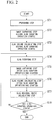
- FIG. 2 is a flowchart showing the slag volume evaluation method according to the present embodiment.
- the slag volume evaluation method according to the present embodiment is a method of evaluating the volume of the slag S floating on the surface of the molten metal M according to a captured image obtained by the first image capturing unit 1 capturing an image of a molten metal surface in the container 4 containing the molten metal M. As shown in FIG.
- the slag volume evaluation method has a preparing step ST1, an image capturing step ST2, the slag volume calculating step ST3, a slag scraping step ST4, an image capturing step ST5, a slag volume calculating step ST6, the slag residual ratio calculating step ST7, and a determining step ST8 of determining whether or not to end slag scraping operations.
- an image of a molten metal surface in a state where a plurality of pieces of the slag S differing from each other in thickness are simultaneously floating on the surface of the molten metal M is captured by using the first image capturing unit 1.
- images of a plurality of molten metal surfaces obtained in different stages of slag scraping operation (partial slag scraping) using the slag scraping apparatus 5 may be captured.
- an image of a single molten metal surface at a certain point of time during slag scraping operation may be captured.
- a plurality of molten metal surfaces which can be obtained in different stages of slag scraping operation can include a molten metal surface before slag scraping operation of the slag S starts (molten metal surface assumed to have the thickest slag S), a molten metal surface in an intermediate stage of slag scraping operation, and a molten metal surface after slag scraping operation ends (molten metal surface assumed to have the thinnest slag S), for example.
- the visual field of the first image capturing unit 1 is set such that not only the molten metal surface of the container 4 but also the container 4 and a background B are included within the visual field.
- the visual field of the first image capturing unit 1 may be set such that only the molten metal surface of the container 4 is included within the visual field.
- the value of a density parameter correlated to the density in a pixel region corresponding to the slag S1 to the slag S3 in the captured image shown in FIG. 3 is calculated.
- the density parameter the temperature can be included as an example, in addition to the density itself. However, in the present embodiment, the density itself is used as a density parameter.
- the average density for the pixel regions corresponding to the slag S1 to the slag S3 is calculated.
- the pixel regions corresponding to the slag S1 to the slag S3 can be recognized by an operator causing the monitor of the image processor 2 to display a captured image and visually recognizing the image.
- the image processor 2 can automatically calculate the average density for the pixel regions corresponding to the slag S1 to the slag S3 when the operator designates the contour of each piece of the slag S1 to the slag S3 while visually recognizing the monitor.
- an approximation curve indicating the correspondence between the thickness and the density of the slag S is calculated by using the value of the average density for the pixel regions corresponding to the slag S1 to the slag S3.
- an approximation curve is calculated by applying a least-squares method, for example, using the values of the thicknesses of a plurality of pieces of the slag S (in the example shown in FIG. 3 , the slag S1 to the slag S3) differing from each other in thickness and the average density for the pixel regions corresponding to the pieces of slag S.
- each piece of slag S can be measured by comparing the dimension of the scraping plate 51 of the slag scraping apparatus 5 in the vertical direction with the slag S, for example.
- a lower surface of the scraping plate 51 is caused to substantially coincide with a lower surface of the slag S (upper surface of the molten metal M) by driving (turning) the arm 52 of the slag scraping apparatus 5 such that a lower end portion of the scraping plate 51 to be buried in the slag S.
- an image of a molten metal surface in the container 4 is captured by the second image capturing unit 3 from above oblique to the vertical direction. Accordingly, a captured image in which both the slag S and the scraping plate 51 are photographed can be obtained.
- a distance HI between a lower surface of the arm 52 and an upper surface of the slag S is calculated.
- the image processor 2 can automatically calculate the distance H1 by designating two points between the lower surface of the arm 52 and the upper surface of the slag S while an operator visually recognizes the monitor.
- the foregoing procedure is executed by sequentially burying the lower end portion of the scraping plate 51 in each piece of the slag S1 to the slag S3, and the thickness of each piece of the slag S1 to the slag S3 is measured.
- I 0 means the value of the density in the pixel region corresponding to the molten metal M (255, in the present embodiment) in a captured image obtained in the preparing step ST1
- e means a base of a natural logarithm
- a means a positive coefficient, respectively.
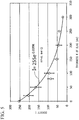
- FIG. 5 is a view showing an example of an approximation curve calculated in the preparing step ST1.
- Data circularly plotted in FIG. 5 indicates the density I in the thickness K of the slag S used in calculating an approximation curve, and a vertically extending bar indicates a fluctuation (standard deviation 1 ⁇ ) in the density of the same thickness K.
- R 2 0.9413
- the preparing step ST1 described above is executed before evaluating the volume of the slag S on the molten metal surface which will actually become an evaluation target. Then, the correspondence (approximation curve) between the thickness K and the density I of the slag S obtained in the preparing step ST1 is stored in the image processor 2, thereby being used in the slag volume calculating step ST3, which will be described below. Specifically, the following Expression (2) is stored in the image processor 2.
- the image processor 2 calculates the thickness K of the slag S for each of pixels constituting a captured image obtained in the image capturing step ST2 according to the value of the density I of each of the pixels constituting the captured image obtained in the image capturing step ST2, and the approximation curve calculated in the preparing step ST1.
- the calculated thickness K of the slag S is adopted as the function of the density I, the following Expression (2) obtained by modifying the foregoing Expression (1) is used.
- the factor "In” in the following Expression (2) means a natural logarithm.
- K I ⁇ 1 / a ⁇ ln I / I 0
- the coefficient a and the density I 0 are stored in the image processor 2. Therefore, the image processor 2 can automatically calculate the thickness K of the slag S corresponding to this density I by substituting the value of the density I of each of the pixels in the foregoing Expression (2).
- FIGS. 6A to 6C are views showing a procedure of calculating the thickness K of the slag S in the slag volume calculating step ST3.
- FIG. 6A is a view schematically showing an example of a captured image obtained in the image capturing step ST2.
- FIG. 6B is an enlarged view (diagram on the left) of a pixel region surrounded by a dotted line A in FIG. 6A , and is a graph (diagram on the right) for calculating the thickness of slag from the density in the pixel region using the approximation curve shown in FIG. 5 .
- FIG. 6C is a view showing the calculated thickness K of the slag S in the pixel region shown in FIG. 6B .
- the foregoing processing described in regard to the pixel region surrounded by the dotted line A is executed for each of the pixels constituting the captured image obtained in the image capturing step ST2.
- the thicknesses of only the pixels positioned on an inner side of the pixel region can be calculated by setting and storing the coordinates of the pixels positioned on an inner side of the pixel region corresponding to the container 4 in the captured image in the image processor 2 in advance.
- the thicknesses of the pixels positioned on an inner side of the pixel region corresponding to the container 4 may be integrated after the thicknesses of all of the pixels constituting the captured image (also including the pixels corresponding to the container 4 and the background B) are calculated.
- the densities in the pixel regions corresponding to the container 4 and the background B are lower than the densities in the pixel regions corresponding to the molten metal M and the slag S. Therefore, for example, only the pixels having a density with a predetermined threshold value or higher may be adopted as a target.
- the visual field of the first image capturing unit 1 may be adjusted in advance such that only an image of the molten metal surface in the container 4 is captured.
- the visual field is adjusted as large as a range in which the container 4 is not photographed.
- the volume of the slag S is calculated by integrating the calculated thickness for each of the pixels.
- an image of the molten metal surface in the container 4 after the slag scraping step ST4 is captured.
- the image capturing conditions and the like are similar to those in the image capturing step ST2.
- the volume of slag in the container 4 after the slag scraping step ST4 is calculated according to the captured image obtained in the image capturing step ST5.
- a calculation method is similar to that in the slag volume calculating step ST3 described above.
- an operator visually recognizes the residual ratio Ps(t) of the slag S displayed in the monitor, determines whether or not it has arrived a desired residual ratio, and decides whether or not to end the slag scraping operation of the slag S (ST8 of FIG. 2 ).
- the slag volume evaluation method according to the present embodiment is completed.
- the slag scraping step ST4 the image capturing step ST5, the slag volume calculating step ST6, and the slag residual ratio calculating step ST7 are repetitively executed.
- an approximation curve indicating the correspondence between the thickness and the density of the slag S is calculated in advance, and the thickness of slag is calculated for each of the pixels constituting a captured image of a molten metal surface which is obtained in the image capturing step ST2 according to this approximation curve and will become an evaluation target. Accordingly, the volume of the slag S can be evaluated more accurately and promptly. Therefore, in the process of the slag scraping operation of the slag S, the slag scraping operation can be optimized by successively evaluating the volume of the slag S remaining in the container 4 such that the slag S does not remain in the container 4 more than necessary.
- the residual ratio of the slag S in the container 4 is calculated in the slag residual ratio calculating step ST7. If this residual ratio is used, when the molten metal M in the container 4 is processed in a post-process, the amount of a sulfur component included in this molten metal M can be estimated. Accordingly, adjustment of the component in the molten metal M in the post-process can be optimized.
- the residual ratio of slag in the container 4 can be calculated in the slag residual ratio calculating step ST7. Therefore, the sulfur component content in slag in a container after the slag scraping operation has started can be calculated according to the calculate residual ratio of the slag and the sulfur component content in the slag in the container before the slag scraping operation starts, which is calculated as described above.
- the sulfur component content in the molten metal when being processed in a post-process can be estimated by using this calculated sulfur component content in the slag in the container after the slag scraping operation has started and the sulfur component content in the molten metal after desulfurization refining calculated by using the sample analysis as described above, in consideration of the returning rate of sulfur from the slag to the molten metal when being processed in the post-process.
- the present embodiment has an advantage in which adjustment of the component in the molten metal in the post-process can be optimized.
- a skilled operator performed a slag scraping operation such that the slag scraping rate of the slag S when the the slag scraping operation ended was within 0.7 to 0.8, while checking the molten metal surface in the container 4 in a visually recognizing manner.
- the residual ratio Ps(t) of the slag S when the the slag scraping operation ended was calculated by using the slag volume evaluation method according to the present embodiment, and the slag scraping rate of the slag S was obtained by the foregoing Expression (5).
- the residual ratio of the slag S was calculated according to the areas of the slag S before the slag scraping operation started and when the slag scraping operation ended, which were calculated by using the method disclosed in Patent Document 1, and the slag scraping rate of the slag S was obtained by the foregoing Expression (5).
- FIG. 7 shows the results.
- FIG. 7 shows standardized values of the slag scraping rate of the slag S obtained by using the slag volume evaluation method according to the present embodiment and the slag scraping rate of the slag S obtained by using the method disclosed in Patent Document 1 while having the slag scraping rate of the slag S determined by an operator in a visually recognizing manner as the standard.
- a value in a bar graph indicates the average value of the tests performed three times, and the bars vertically extending in the bar graph indicate the fluctuations (standard deviation 1 ⁇ ).
- the slag scraping rate of the slag S obtained by using the method disclosed in Patent Document 1 was 0.70 ⁇ 0.08.
- the slag scraping rate of the slag S obtained by using the slag volume evaluation method according to the present embodiment was 0.98 ⁇ 0.06. That is, it was assumed that the slag scraping rate of the slag S by the slag volume evaluation method according to the present embodiment was closer to that obtained by the sense of the skilled operator and was more accurate than the slag scraping rate by the method disclosed in Patent Document 1.
- the foregoing embodiment shows a case where the approximation curve (refer to FIG. 5 ) expressed by the foregoing Expression (1) is calculated in the preparing step ST1. Since the relationship between the thickness K and the density I of slag as shown in FIG. 5 is obtained in the preparing step ST1 according to radiation light of the molten metal M which is incident on the first image capturing unit 1 and is transmitted through the slag S, there are many cases where the thickness K and the density I can be approximated with the exponential function as in Expression (1).
- the approximation curve is not limited to Expression (1) and need only to be capable of fitting the measurement data of the thickness and the density of slag.
- I I 0 / aK 3 + bK 2 + cK + 1
- the foregoing embodiment shows a case where the thickness K of the slag S is measured in the preparing step ST1 (refer to FIG. 1 ) according to an image captured by the second image capturing unit 3, in a state where the lower surface of the scraping plate 51 substantially coincides with the lower surface of the slag S (upper surface of the molten metal M).
- a pair of laser distance meters which are non-contact distance meters disposed at the same height as each other above the scraping plate 51 may be used. In this case, the distance to the upper surface of the slag S is measured by one laser distance meter, and the distance to the upper surface of the arm 52 is measured by the other laser distance meter.
- the measurement result of the other laser distance meter is subtracted from the measurement result of one laser distance meter, and the dimension of the arm 52 in the vertical direction is subtracted, so that the distance HI between the lower surface of the arm 52 and the upper surface of the slag S can be calculated.
- the thickness K of the slag S may be measured by subtracting the distance HI calculated in this manner from H0.
- the thickness K of the slag S may be measured according to the difference between these measurement results by measuring the distance to the upper surface of the slag S using one laser distance meter and measuring the distance to the surface of the molten metal M using the other laser distance meter.
- the thickness K of the slag S may be measured by using a measuring rod. In these cases, there is no need to measure the distance HI.
- the foregoing embodiment is separately provided with the first image capturing unit 1 which is used for the purpose of obtaining a captured image for evaluating the volume of the slag S in the slag volume calculating step ST3, and the second image capturing unit 3 which is used for the purpose of calculating the thickness K of the slag S in the preparing step ST1.
- the second image capturing unit 3 may be used for the purpose of calculating the thickness K of the slag S and may be simultaneously used for purpose of obtaining a captured image for evaluating the volume of the slag S.
- the second image capturing unit 3 to perform image capturing from above oblique to the vertical direction in order to calculate the distance HI between the lower surface of the arm 52 and the upper surface of the slag S. Therefore, there is concern that when the visual-line angle ⁇ increases, the difference in resolution per pixel between a part on a side closer to the second image capturing unit 3 and a part on a side farther therefrom on the molten metal surface of the container 4 will increase, and even if the thickness of the slag S is the same as each other, a difference will be caused between the densities in the pixel regions. In this manner, since there is concern that the calculation accuracy in the volume of slag will be adversely affected, it is preferable to use the first image capturing unit 1 and the second image capturing unit 3 as in the foregoing embodiment.
- the first image capturing unit 1 may be adjusted such that the density in the pixel region corresponding to the molten metal M is within 250 to 255 (such that the densities other than the absolute maximum value are also included).
- the density I 0 in the foregoing Expression (1), Expression (2), and Expression (3) the minimum value (250 in the foregoing example) of the density in the pixel region corresponding to the molten metal M may be used.
- the approximation curve expressed by the foregoing Expression (1) is calculated.
- the coefficient a in Expression (1) the thickness and the density of slag are measured while changing the component of the slag and the temperature of a molten steel. Consequently, it has been ascertained that the coefficient a is approximately uniform without depending on the component of slag and the temperature of a molten steel. Therefore, when an approximation curve indicating the correspondence between the thickness K and the density I of slag are obtained once, even if the component of slag and the temperature of a molten steel change, the approximation curve can be used.
Landscapes
- Engineering & Computer Science (AREA)
- Physics & Mathematics (AREA)
- General Physics & Mathematics (AREA)
- Chemical & Material Sciences (AREA)
- Mechanical Engineering (AREA)
- Health & Medical Sciences (AREA)
- Life Sciences & Earth Sciences (AREA)
- Analytical Chemistry (AREA)
- Biochemistry (AREA)
- General Health & Medical Sciences (AREA)
- Immunology (AREA)
- Pathology (AREA)
- Fluid Mechanics (AREA)
- General Engineering & Computer Science (AREA)
- Food Science & Technology (AREA)
- Medicinal Chemistry (AREA)
- Materials Engineering (AREA)
- Organic Chemistry (AREA)
- Theoretical Computer Science (AREA)
- Computer Vision & Pattern Recognition (AREA)
- Manufacturing & Machinery (AREA)
- Metallurgy (AREA)
- Quality & Reliability (AREA)
- Geometry (AREA)
- Waste-Gas Treatment And Other Accessory Devices For Furnaces (AREA)
- Measurement Of Levels Of Liquids Or Fluent Solid Materials (AREA)
- Length Measuring Devices By Optical Means (AREA)
- Casting Support Devices, Ladles, And Melt Control Thereby (AREA)
- Carbon Steel Or Casting Steel Manufacturing (AREA)
- Investigating Or Analysing Materials By Optical Means (AREA)
Applications Claiming Priority (2)
| Application Number | Priority Date | Filing Date | Title |
|---|---|---|---|
| JP2016236936 | 2016-12-06 | ||
| PCT/JP2017/043809 WO2018105652A1 (ja) | 2016-12-06 | 2017-12-06 | 溶融金属表面のスラグ体積評価方法 |
Publications (2)
| Publication Number | Publication Date |
|---|---|
| EP3553463A1 true EP3553463A1 (de) | 2019-10-16 |
| EP3553463A4 EP3553463A4 (de) | 2020-07-29 |
Family
ID=62492296
Family Applications (1)
| Application Number | Title | Priority Date | Filing Date |
|---|---|---|---|
| EP17879407.9A Withdrawn EP3553463A4 (de) | 2016-12-06 | 2017-12-06 | Verfahren zur beurteilung der schlackenmenge auf der oberfläche von geschmolzenem metall |
Country Status (8)
| Country | Link |
|---|---|
| US (1) | US10845352B2 (de) |
| EP (1) | EP3553463A4 (de) |
| JP (1) | JP6687125B2 (de) |
| KR (1) | KR102189118B1 (de) |
| CN (2) | CN110036257A (de) |
| CA (1) | CA3045408A1 (de) |
| TW (1) | TWI657880B (de) |
| WO (1) | WO2018105652A1 (de) |
Families Citing this family (17)
| Publication number | Priority date | Publication date | Assignee | Title |
|---|---|---|---|---|
| WO2019227224A1 (en) * | 2018-06-01 | 2019-12-05 | Dynamic Concept Inc. | System for measuring level and quality of a metal in a furnace |
| JP7256365B2 (ja) * | 2019-01-11 | 2023-04-12 | 日本製鉄株式会社 | スラグの定量化方法 |
| TWI700372B (zh) * | 2019-09-11 | 2020-08-01 | 中國鋼鐵股份有限公司 | 高爐設備及高爐爐渣液位之監測方法 |
| KR102251035B1 (ko) * | 2019-09-30 | 2021-05-12 | 주식회사 포스코 | 슬래그 배재 장치 및 슬래그 배재 방법 |
| CN110666150A (zh) * | 2019-10-09 | 2020-01-10 | 长沙有色冶金设计研究院有限公司 | 金属铸锭扒渣系统及方法 |
| JP7472536B2 (ja) * | 2020-02-25 | 2024-04-23 | スズキ株式会社 | 溶解炉湯面検出方法及び装置 |
| CN112828275B (zh) * | 2020-12-30 | 2022-08-09 | 北京首钢自动化信息技术有限公司 | 一种自动扒渣方法、装置及系统 |
| CN113033335B (zh) * | 2021-03-08 | 2021-10-08 | 柳州钢铁股份有限公司 | 一种基于炉渣智能分析及三维模型的转炉留渣量计算方法 |
| CN113096083B (zh) * | 2021-03-30 | 2022-11-01 | 湖南镭目科技有限公司 | 一种对炉口钢渣的识别方法、装置、设备及存储介质 |
| AU2022305124A1 (en) * | 2021-07-02 | 2024-02-15 | Noda Technologies Ab | A method for determining at least one property of an aluminium production bath in of an aluminium production cell, a system for determining the at least one property, and a probe for capturing a sample from the aluminium production cell |
| CN113986896B (zh) * | 2021-10-14 | 2024-07-23 | 中冶南方工程技术有限公司 | 一种渣皮厚度数据滤波的方法和装置 |
| KR102670728B1 (ko) * | 2022-05-11 | 2024-05-30 | 주식회사 포스코 | 슬래그의 식별 방법, 슬래그의 배재 방법 및 슬래그 배재 장치 |
| CN117165733A (zh) * | 2022-05-27 | 2023-12-05 | 宝山钢铁股份有限公司 | 一种转炉自动倒渣的渣量实时识别方法及系统 |
| CN115631164B (zh) * | 2022-10-23 | 2025-11-28 | 甘肃东兴铝业有限公司 | 一种铝熔体炉内精炼工艺水平的评价方法 |
| CN117428183B (zh) * | 2023-12-20 | 2024-03-26 | 苏州朗信智能科技有限公司 | 基于图像识别的扒渣控制方法、系统、设备及介质 |
| CN119489184B (zh) * | 2024-09-27 | 2025-10-31 | 武汉钢铁有限公司 | 一种中包水口的检测方法、装置、电子设备及存储介质 |
| CN119979949A (zh) * | 2025-04-10 | 2025-05-13 | 宁波得鑫科技有限公司 | 一种镁铝合金生产方法及系统 |
Family Cites Families (26)
| Publication number | Priority date | Publication date | Assignee | Title |
|---|---|---|---|---|
| US3080755A (en) * | 1960-10-12 | 1963-03-12 | Percy James Ward | Metallurgical process control |
| US5301621A (en) * | 1993-05-17 | 1994-04-12 | Rollins Environmental Services, Inc. | Slag viscosity detection through image analysis of dripping slag within rotary incineration kilns |
| US5694480A (en) * | 1995-08-30 | 1997-12-02 | Tsukishima Kikai Co., Ltd. | Molten slag flow rate measuring device and furnace facilities using the same |
| DE19614760A1 (de) * | 1996-04-02 | 1997-10-09 | Mannesmann Ag | Verfahren zur Optimierung der Strangoberflächenqualität |
| US6197086B1 (en) * | 1997-11-13 | 2001-03-06 | Bethlehem Steel Corporation | System and method for minimizing slag carryover during the production of steel |
| US5968227A (en) * | 1997-11-13 | 1999-10-19 | Bethlehem Steel Corporation | System and method for minimizing slag carryover during the tapping of a BOF converter in the production of steel |
| US6130637A (en) * | 1998-08-18 | 2000-10-10 | Usx Corporation | Measuring the thickness of hot slag in steelmaking |
| US6166681A (en) * | 1998-08-18 | 2000-12-26 | Usx Corporation | Measuring the thickness of materials |
| US6562285B1 (en) * | 2000-11-15 | 2003-05-13 | Metallurgical Sensors, Inc. | Method and apparatus for detecting slag carryover |
| US6576039B2 (en) * | 2001-07-02 | 2003-06-10 | Tetron, Inc. | Method and apparatus for metal pouring |
| JP3565340B2 (ja) | 2001-07-03 | 2004-09-15 | Jfeスチール株式会社 | スラグ検知方法、スラグ検知装置及び除滓装置 |
| JP3778015B2 (ja) * | 2001-07-03 | 2006-05-24 | Jfeスチール株式会社 | スラグ検知方法、スラグ検知装置、及び除滓装置 |
| EP1424543B1 (de) * | 2001-07-27 | 2014-05-21 | Nippon Steel & Sumitomo Metal Corporation | Instrument zur messung der temperatur von geschmolzenem metall |
| JP2004144652A (ja) * | 2002-10-25 | 2004-05-20 | Fuji Photo Film Co Ltd | 被検物測定装置 |
| CN1238138C (zh) * | 2002-12-20 | 2006-01-25 | 宝山钢铁股份有限公司 | 自动扒渣方法 |
| JP4648820B2 (ja) * | 2005-10-27 | 2011-03-09 | 新日本製鐵株式会社 | 極低硫含クロム溶鋼の製造方法 |
| US7468090B2 (en) * | 2005-11-28 | 2008-12-23 | Nupro Corporation | Method for tapping a steel making furnace |
| JP5448669B2 (ja) * | 2009-09-17 | 2014-03-19 | 三菱重工業株式会社 | 石炭ガス化炉のスラグ監視装置及び石炭ガス化炉 |
| CN102183288B (zh) * | 2011-03-03 | 2013-01-02 | 浙江大学 | 基于远程红外监测的精炼铝用量控制方法 |
| EP2760610A4 (de) * | 2011-09-29 | 2015-08-05 | Ramchandra Harisa Tupkary | Schlackenpfanne zur trennung und wiedergewinnung von eisenschmelze aus schlacke |
| JP5692109B2 (ja) * | 2012-02-03 | 2015-04-01 | 新日鐵住金株式会社 | 高炉出銑温度測定方法、高炉出銑温度測定システム、コンピュータプログラム、及びコンピュータ読み取り可能な記憶媒体 |
| DE102012211714A1 (de) * | 2012-07-05 | 2014-05-22 | Siemens Vai Metals Technologies Gmbh | Verfahren und Vorrichtung zur Detektion des Schlackepegels in einem metallurgischen Gefäß |
| CN103063150A (zh) * | 2012-12-19 | 2013-04-24 | 浙江大学 | 基于数字图像处理技术的灰渣厚度监测方法及装置 |
| KR101704982B1 (ko) * | 2013-07-29 | 2017-02-08 | 제이에프이 스틸 가부시키가이샤 | 이상 검지 방법 및 고로 조업 방법 |
| CN104232837B (zh) * | 2014-09-24 | 2016-08-24 | 杭州谱诚泰迪实业有限公司 | 一种转炉/电炉出钢监测装置及控制方法 |
| CN105160683B (zh) * | 2015-09-29 | 2019-01-15 | 田陆 | 一种基于人工干预的铁水扒渣检测与控制系统及其方法 |
-
2017
- 2017-12-06 WO PCT/JP2017/043809 patent/WO2018105652A1/ja not_active Ceased
- 2017-12-06 KR KR1020197015565A patent/KR102189118B1/ko active Active
- 2017-12-06 CN CN201780075201.XA patent/CN110036257A/zh active Pending
- 2017-12-06 CA CA3045408A patent/CA3045408A1/en not_active Abandoned
- 2017-12-06 US US16/466,154 patent/US10845352B2/en active Active
- 2017-12-06 EP EP17879407.9A patent/EP3553463A4/de not_active Withdrawn
- 2017-12-06 CN CN202410005339.4A patent/CN117804568A/zh active Pending
- 2017-12-06 JP JP2018555038A patent/JP6687125B2/ja active Active
- 2017-12-06 TW TW106142738A patent/TWI657880B/zh not_active IP Right Cessation
Also Published As
| Publication number | Publication date |
|---|---|
| US20200064326A1 (en) | 2020-02-27 |
| JPWO2018105652A1 (ja) | 2019-06-24 |
| US10845352B2 (en) | 2020-11-24 |
| TW201827143A (zh) | 2018-08-01 |
| TWI657880B (zh) | 2019-05-01 |
| JP6687125B2 (ja) | 2020-04-22 |
| CN117804568A (zh) | 2024-04-02 |
| CA3045408A1 (en) | 2018-06-14 |
| KR102189118B1 (ko) | 2020-12-09 |
| CN110036257A (zh) | 2019-07-19 |
| WO2018105652A1 (ja) | 2018-06-14 |
| EP3553463A4 (de) | 2020-07-29 |
| BR112019010774A2 (pt) | 2019-10-01 |
| KR20190077049A (ko) | 2019-07-02 |
Similar Documents
| Publication | Publication Date | Title |
|---|---|---|
| US10845352B2 (en) | Slag volume evaluation method for molten metal surface | |
| EP3182060B1 (de) | Formkontrollvorrichtung für einen metallkörper und formkontrollverfahren für einen metallkörper | |
| EP3584329A1 (de) | Verfahren zur detektion von schlacke in stahlschmelzefluss | |
| JP5381565B2 (ja) | 画像処理装置、画像処理用プログラムおよび画像処理方法 | |
| CN106670449A (zh) | 一种铁水扒渣测控方法 | |
| JP2006119110A (ja) | 高炉出銑温度測定方法及び測定装置 | |
| TW201600223A (zh) | 工具檢查方法及工具檢查裝置 | |
| JP7256365B2 (ja) | スラグの定量化方法 | |
| JP4669420B2 (ja) | 高炉出銑温度測定システム、高炉出銑温度測定方法、及びコンピュータプログラム | |
| EP2554959A1 (de) | Verfahren und Vorrichtung zum Messen der Temperatur von heißem geschmolzenem Metall | |
| JP2005532557A (ja) | 溶融相のオンライン測定のための方法 | |
| JP2012026820A (ja) | ブラスト後の除錆度検査システム | |
| JP2007246959A (ja) | 高炉出銑流測定システム、高炉出銑流測定方法、及びコンピュータプログラム | |
| KR101590552B1 (ko) | 곡선형 스프링 형상 검사 방법 | |
| KR20220154345A (ko) | 가우시안 가중치 최소 자승법을 이용하는 영상 처리 장치 및 그것의 윤곽선 검출 방법 | |
| CN108986080B (zh) | 一种射线数字图像调制度确定方法及应用 | |
| EP3584328A1 (de) | Verfahren zur erkennung von schlacke in einem stahlschmelzefluss | |
| JP6010972B2 (ja) | 地金付着度測定方法および地金付着度測定装置 | |
| JPH0720059A (ja) | 透視歪の測定方法および装置 | |
| WO2023286519A1 (ja) | デブリ判定方法 | |
| BR112019010774B1 (pt) | Método de avaliação do volume de escória para uma superfície de metal fundido | |
| Huang et al. | A digital analysis approach for estimating decarburization layer depth of carbon steel via a portable device | |
| CN109874009A (zh) | 一种基于主目标区域约束的射线底片图像曝光质量评定方法 | |
| JP2009288135A (ja) | 欠陥計数装置及び欠陥計数方法 |
Legal Events
| Date | Code | Title | Description |
|---|---|---|---|
| STAA | Information on the status of an ep patent application or granted ep patent |
Free format text: STATUS: THE INTERNATIONAL PUBLICATION HAS BEEN MADE |
|
| PUAI | Public reference made under article 153(3) epc to a published international application that has entered the european phase |
Free format text: ORIGINAL CODE: 0009012 |
|
| STAA | Information on the status of an ep patent application or granted ep patent |
Free format text: STATUS: REQUEST FOR EXAMINATION WAS MADE |
|
| 17P | Request for examination filed |
Effective date: 20190628 |
|
| AK | Designated contracting states |
Kind code of ref document: A1 Designated state(s): AL AT BE BG CH CY CZ DE DK EE ES FI FR GB GR HR HU IE IS IT LI LT LU LV MC MK MT NL NO PL PT RO RS SE SI SK SM TR |
|
| AX | Request for extension of the european patent |
Extension state: BA ME |
|
| DAV | Request for validation of the european patent (deleted) | ||
| DAX | Request for extension of the european patent (deleted) | ||
| A4 | Supplementary search report drawn up and despatched |
Effective date: 20200630 |
|
| RIC1 | Information provided on ipc code assigned before grant |
Ipc: B22D 37/00 20060101ALI20200624BHEP Ipc: G01N 33/205 20190101ALI20200624BHEP Ipc: F27D 21/00 20060101ALI20200624BHEP Ipc: G01B 11/00 20060101ALI20200624BHEP Ipc: F27D 21/02 20060101ALI20200624BHEP Ipc: G01B 11/06 20060101AFI20200624BHEP Ipc: G01F 17/00 20060101ALI20200624BHEP Ipc: G01N 33/20 20190101ALI20200624BHEP Ipc: B22D 43/00 20060101ALI20200624BHEP Ipc: G06T 7/00 20170101ALI20200624BHEP Ipc: C21B 3/04 20060101ALI20200624BHEP |
|
| STAA | Information on the status of an ep patent application or granted ep patent |
Free format text: STATUS: THE APPLICATION IS DEEMED TO BE WITHDRAWN |
|
| 18D | Application deemed to be withdrawn |
Effective date: 20210128 |