EP3553300A1 - Startsteuergerät und startsteuerungsverfahren - Google Patents
Startsteuergerät und startsteuerungsverfahren Download PDFInfo
- Publication number
- EP3553300A1 EP3553300A1 EP19163369.2A EP19163369A EP3553300A1 EP 3553300 A1 EP3553300 A1 EP 3553300A1 EP 19163369 A EP19163369 A EP 19163369A EP 3553300 A1 EP3553300 A1 EP 3553300A1
- Authority
- EP
- European Patent Office
- Prior art keywords
- engine
- motor generator
- angle
- stopping
- crank
- Prior art date
- Legal status (The legal status is an assumption and is not a legal conclusion. Google has not performed a legal analysis and makes no representation as to the accuracy of the status listed.)
- Granted
Links
Images


Classifications
-
- B—PERFORMING OPERATIONS; TRANSPORTING
- B60—VEHICLES IN GENERAL
- B60W—CONJOINT CONTROL OF VEHICLE SUB-UNITS OF DIFFERENT TYPE OR DIFFERENT FUNCTION; CONTROL SYSTEMS SPECIALLY ADAPTED FOR HYBRID VEHICLES; ROAD VEHICLE DRIVE CONTROL SYSTEMS FOR PURPOSES NOT RELATED TO THE CONTROL OF A PARTICULAR SUB-UNIT
- B60W20/00—Control systems specially adapted for hybrid vehicles
- B60W20/40—Controlling the engagement or disengagement of prime movers, e.g. for transition between prime movers
-
- F—MECHANICAL ENGINEERING; LIGHTING; HEATING; WEAPONS; BLASTING
- F02—COMBUSTION ENGINES; HOT-GAS OR COMBUSTION-PRODUCT ENGINE PLANTS
- F02D—CONTROLLING COMBUSTION ENGINES
- F02D41/00—Electrical control of supply of combustible mixture or its constituents
- F02D41/02—Circuit arrangements for generating control signals
- F02D41/04—Introducing corrections for particular operating conditions
- F02D41/06—Introducing corrections for particular operating conditions for engine starting or warming up
- F02D41/062—Introducing corrections for particular operating conditions for engine starting or warming up for starting
- F02D41/065—Introducing corrections for particular operating conditions for engine starting or warming up for starting at hot start or restart
-
- B—PERFORMING OPERATIONS; TRANSPORTING
- B60—VEHICLES IN GENERAL
- B60K—ARRANGEMENT OR MOUNTING OF PROPULSION UNITS OR OF TRANSMISSIONS IN VEHICLES; ARRANGEMENT OR MOUNTING OF PLURAL DIVERSE PRIME-MOVERS IN VEHICLES; AUXILIARY DRIVES FOR VEHICLES; INSTRUMENTATION OR DASHBOARDS FOR VEHICLES; ARRANGEMENTS IN CONNECTION WITH COOLING, AIR INTAKE, GAS EXHAUST OR FUEL SUPPLY OF PROPULSION UNITS IN VEHICLES
- B60K6/00—Arrangement or mounting of plural diverse prime-movers for mutual or common propulsion, e.g. hybrid propulsion systems comprising electric motors and internal combustion engines
- B60K6/20—Arrangement or mounting of plural diverse prime-movers for mutual or common propulsion, e.g. hybrid propulsion systems comprising electric motors and internal combustion engines the prime-movers consisting of electric motors and internal combustion engines, e.g. HEVs
- B60K6/22—Arrangement or mounting of plural diverse prime-movers for mutual or common propulsion, e.g. hybrid propulsion systems comprising electric motors and internal combustion engines the prime-movers consisting of electric motors and internal combustion engines, e.g. HEVs characterised by apparatus, components or means specially adapted for HEVs
- B60K6/24—Arrangement or mounting of plural diverse prime-movers for mutual or common propulsion, e.g. hybrid propulsion systems comprising electric motors and internal combustion engines the prime-movers consisting of electric motors and internal combustion engines, e.g. HEVs characterised by apparatus, components or means specially adapted for HEVs characterised by the combustion engines
-
- B—PERFORMING OPERATIONS; TRANSPORTING
- B60—VEHICLES IN GENERAL
- B60K—ARRANGEMENT OR MOUNTING OF PROPULSION UNITS OR OF TRANSMISSIONS IN VEHICLES; ARRANGEMENT OR MOUNTING OF PLURAL DIVERSE PRIME-MOVERS IN VEHICLES; AUXILIARY DRIVES FOR VEHICLES; INSTRUMENTATION OR DASHBOARDS FOR VEHICLES; ARRANGEMENTS IN CONNECTION WITH COOLING, AIR INTAKE, GAS EXHAUST OR FUEL SUPPLY OF PROPULSION UNITS IN VEHICLES
- B60K6/00—Arrangement or mounting of plural diverse prime-movers for mutual or common propulsion, e.g. hybrid propulsion systems comprising electric motors and internal combustion engines
- B60K6/20—Arrangement or mounting of plural diverse prime-movers for mutual or common propulsion, e.g. hybrid propulsion systems comprising electric motors and internal combustion engines the prime-movers consisting of electric motors and internal combustion engines, e.g. HEVs
- B60K6/22—Arrangement or mounting of plural diverse prime-movers for mutual or common propulsion, e.g. hybrid propulsion systems comprising electric motors and internal combustion engines the prime-movers consisting of electric motors and internal combustion engines, e.g. HEVs characterised by apparatus, components or means specially adapted for HEVs
- B60K6/26—Arrangement or mounting of plural diverse prime-movers for mutual or common propulsion, e.g. hybrid propulsion systems comprising electric motors and internal combustion engines the prime-movers consisting of electric motors and internal combustion engines, e.g. HEVs characterised by apparatus, components or means specially adapted for HEVs characterised by the motors or the generators
-
- B—PERFORMING OPERATIONS; TRANSPORTING
- B60—VEHICLES IN GENERAL
- B60W—CONJOINT CONTROL OF VEHICLE SUB-UNITS OF DIFFERENT TYPE OR DIFFERENT FUNCTION; CONTROL SYSTEMS SPECIALLY ADAPTED FOR HYBRID VEHICLES; ROAD VEHICLE DRIVE CONTROL SYSTEMS FOR PURPOSES NOT RELATED TO THE CONTROL OF A PARTICULAR SUB-UNIT
- B60W10/00—Conjoint control of vehicle sub-units of different type or different function
- B60W10/04—Conjoint control of vehicle sub-units of different type or different function including control of propulsion units
- B60W10/06—Conjoint control of vehicle sub-units of different type or different function including control of propulsion units including control of combustion engines
-
- B—PERFORMING OPERATIONS; TRANSPORTING
- B60—VEHICLES IN GENERAL
- B60W—CONJOINT CONTROL OF VEHICLE SUB-UNITS OF DIFFERENT TYPE OR DIFFERENT FUNCTION; CONTROL SYSTEMS SPECIALLY ADAPTED FOR HYBRID VEHICLES; ROAD VEHICLE DRIVE CONTROL SYSTEMS FOR PURPOSES NOT RELATED TO THE CONTROL OF A PARTICULAR SUB-UNIT
- B60W10/00—Conjoint control of vehicle sub-units of different type or different function
- B60W10/04—Conjoint control of vehicle sub-units of different type or different function including control of propulsion units
- B60W10/08—Conjoint control of vehicle sub-units of different type or different function including control of propulsion units including control of electric propulsion units, e.g. motors or generators
-
- B—PERFORMING OPERATIONS; TRANSPORTING
- B60—VEHICLES IN GENERAL
- B60W—CONJOINT CONTROL OF VEHICLE SUB-UNITS OF DIFFERENT TYPE OR DIFFERENT FUNCTION; CONTROL SYSTEMS SPECIALLY ADAPTED FOR HYBRID VEHICLES; ROAD VEHICLE DRIVE CONTROL SYSTEMS FOR PURPOSES NOT RELATED TO THE CONTROL OF A PARTICULAR SUB-UNIT
- B60W20/00—Control systems specially adapted for hybrid vehicles
- B60W20/10—Controlling the power contribution of each of the prime movers to meet required power demand
-
- B—PERFORMING OPERATIONS; TRANSPORTING
- B60—VEHICLES IN GENERAL
- B60W—CONJOINT CONTROL OF VEHICLE SUB-UNITS OF DIFFERENT TYPE OR DIFFERENT FUNCTION; CONTROL SYSTEMS SPECIALLY ADAPTED FOR HYBRID VEHICLES; ROAD VEHICLE DRIVE CONTROL SYSTEMS FOR PURPOSES NOT RELATED TO THE CONTROL OF A PARTICULAR SUB-UNIT
- B60W30/00—Purposes of road vehicle drive control systems not related to the control of a particular sub-unit, e.g. of systems using conjoint control of vehicle sub-units
- B60W30/18—Propelling the vehicle
- B60W30/18009—Propelling the vehicle related to particular drive situations
- B60W30/18054—Propelling the vehicle related to particular drive situations at stand still, e.g. engine in idling state
-
- F—MECHANICAL ENGINEERING; LIGHTING; HEATING; WEAPONS; BLASTING
- F02—COMBUSTION ENGINES; HOT-GAS OR COMBUSTION-PRODUCT ENGINE PLANTS
- F02D—CONTROLLING COMBUSTION ENGINES
- F02D41/00—Electrical control of supply of combustible mixture or its constituents
- F02D41/0002—Controlling intake air
-
- F—MECHANICAL ENGINEERING; LIGHTING; HEATING; WEAPONS; BLASTING
- F02—COMBUSTION ENGINES; HOT-GAS OR COMBUSTION-PRODUCT ENGINE PLANTS
- F02D—CONTROLLING COMBUSTION ENGINES
- F02D41/00—Electrical control of supply of combustible mixture or its constituents
- F02D41/02—Circuit arrangements for generating control signals
- F02D41/04—Introducing corrections for particular operating conditions
- F02D41/042—Introducing corrections for particular operating conditions for stopping the engine
-
- F—MECHANICAL ENGINEERING; LIGHTING; HEATING; WEAPONS; BLASTING
- F02—COMBUSTION ENGINES; HOT-GAS OR COMBUSTION-PRODUCT ENGINE PLANTS
- F02D—CONTROLLING COMBUSTION ENGINES
- F02D41/00—Electrical control of supply of combustible mixture or its constituents
- F02D41/02—Circuit arrangements for generating control signals
- F02D41/04—Introducing corrections for particular operating conditions
- F02D41/06—Introducing corrections for particular operating conditions for engine starting or warming up
- F02D41/062—Introducing corrections for particular operating conditions for engine starting or warming up for starting
-
- F—MECHANICAL ENGINEERING; LIGHTING; HEATING; WEAPONS; BLASTING
- F02—COMBUSTION ENGINES; HOT-GAS OR COMBUSTION-PRODUCT ENGINE PLANTS
- F02D—CONTROLLING COMBUSTION ENGINES
- F02D41/00—Electrical control of supply of combustible mixture or its constituents
- F02D41/02—Circuit arrangements for generating control signals
- F02D41/04—Introducing corrections for particular operating conditions
- F02D41/12—Introducing corrections for particular operating conditions for deceleration
- F02D41/123—Introducing corrections for particular operating conditions for deceleration the fuel injection being cut-off
-
- F—MECHANICAL ENGINEERING; LIGHTING; HEATING; WEAPONS; BLASTING
- F02—COMBUSTION ENGINES; HOT-GAS OR COMBUSTION-PRODUCT ENGINE PLANTS
- F02D—CONTROLLING COMBUSTION ENGINES
- F02D41/00—Electrical control of supply of combustible mixture or its constituents
- F02D41/30—Controlling fuel injection
- F02D41/3094—Controlling fuel injection the fuel injection being effected by at least two different injectors, e.g. one in the intake manifold and one in the cylinder
-
- F—MECHANICAL ENGINEERING; LIGHTING; HEATING; WEAPONS; BLASTING
- F02—COMBUSTION ENGINES; HOT-GAS OR COMBUSTION-PRODUCT ENGINE PLANTS
- F02D—CONTROLLING COMBUSTION ENGINES
- F02D9/00—Controlling engines by throttling air or fuel-and-air induction conduits or exhaust conduits
- F02D9/02—Controlling engines by throttling air or fuel-and-air induction conduits or exhaust conduits concerning induction conduits
-
- F—MECHANICAL ENGINEERING; LIGHTING; HEATING; WEAPONS; BLASTING
- F02—COMBUSTION ENGINES; HOT-GAS OR COMBUSTION-PRODUCT ENGINE PLANTS
- F02N—STARTING OF COMBUSTION ENGINES; STARTING AIDS FOR SUCH ENGINES, NOT OTHERWISE PROVIDED FOR
- F02N11/00—Starting of engines by means of electric motors
-
- F—MECHANICAL ENGINEERING; LIGHTING; HEATING; WEAPONS; BLASTING
- F02—COMBUSTION ENGINES; HOT-GAS OR COMBUSTION-PRODUCT ENGINE PLANTS
- F02N—STARTING OF COMBUSTION ENGINES; STARTING AIDS FOR SUCH ENGINES, NOT OTHERWISE PROVIDED FOR
- F02N11/00—Starting of engines by means of electric motors
- F02N11/04—Starting of engines by means of electric motors the motors being associated with current generators
-
- F—MECHANICAL ENGINEERING; LIGHTING; HEATING; WEAPONS; BLASTING
- F02—COMBUSTION ENGINES; HOT-GAS OR COMBUSTION-PRODUCT ENGINE PLANTS
- F02N—STARTING OF COMBUSTION ENGINES; STARTING AIDS FOR SUCH ENGINES, NOT OTHERWISE PROVIDED FOR
- F02N11/00—Starting of engines by means of electric motors
- F02N11/08—Circuits specially adapted for starting of engines
- F02N11/0814—Circuits specially adapted for starting of engines comprising means for controlling automatic idle-start-stop
- F02N11/0818—Conditions for starting or stopping the engine or for deactivating the idle-start-stop mode
- F02N11/0825—Conditions for starting or stopping the engine or for deactivating the idle-start-stop mode related to prevention of engine restart failure, e.g. disabling automatic stop at low battery state
-
- F—MECHANICAL ENGINEERING; LIGHTING; HEATING; WEAPONS; BLASTING
- F02—COMBUSTION ENGINES; HOT-GAS OR COMBUSTION-PRODUCT ENGINE PLANTS
- F02N—STARTING OF COMBUSTION ENGINES; STARTING AIDS FOR SUCH ENGINES, NOT OTHERWISE PROVIDED FOR
- F02N11/00—Starting of engines by means of electric motors
- F02N11/08—Circuits specially adapted for starting of engines
- F02N11/0848—Circuits specially adapted for starting of engines with means for detecting successful engine start, e.g. to stop starter actuation
-
- F—MECHANICAL ENGINEERING; LIGHTING; HEATING; WEAPONS; BLASTING
- F02—COMBUSTION ENGINES; HOT-GAS OR COMBUSTION-PRODUCT ENGINE PLANTS
- F02N—STARTING OF COMBUSTION ENGINES; STARTING AIDS FOR SUCH ENGINES, NOT OTHERWISE PROVIDED FOR
- F02N19/00—Starting aids for combustion engines, not otherwise provided for
- F02N19/005—Aiding engine start by starting from a predetermined position, e.g. pre-positioning or reverse rotation
-
- B—PERFORMING OPERATIONS; TRANSPORTING
- B60—VEHICLES IN GENERAL
- B60W—CONJOINT CONTROL OF VEHICLE SUB-UNITS OF DIFFERENT TYPE OR DIFFERENT FUNCTION; CONTROL SYSTEMS SPECIALLY ADAPTED FOR HYBRID VEHICLES; ROAD VEHICLE DRIVE CONTROL SYSTEMS FOR PURPOSES NOT RELATED TO THE CONTROL OF A PARTICULAR SUB-UNIT
- B60W2510/00—Input parameters relating to a particular sub-units
- B60W2510/06—Combustion engines, Gas turbines
- B60W2510/0685—Engine crank angle
-
- B—PERFORMING OPERATIONS; TRANSPORTING
- B60—VEHICLES IN GENERAL
- B60W—CONJOINT CONTROL OF VEHICLE SUB-UNITS OF DIFFERENT TYPE OR DIFFERENT FUNCTION; CONTROL SYSTEMS SPECIALLY ADAPTED FOR HYBRID VEHICLES; ROAD VEHICLE DRIVE CONTROL SYSTEMS FOR PURPOSES NOT RELATED TO THE CONTROL OF A PARTICULAR SUB-UNIT
- B60W2710/00—Output or target parameters relating to a particular sub-units
- B60W2710/06—Combustion engines, Gas turbines
-
- B—PERFORMING OPERATIONS; TRANSPORTING
- B60—VEHICLES IN GENERAL
- B60W—CONJOINT CONTROL OF VEHICLE SUB-UNITS OF DIFFERENT TYPE OR DIFFERENT FUNCTION; CONTROL SYSTEMS SPECIALLY ADAPTED FOR HYBRID VEHICLES; ROAD VEHICLE DRIVE CONTROL SYSTEMS FOR PURPOSES NOT RELATED TO THE CONTROL OF A PARTICULAR SUB-UNIT
- B60W2710/00—Output or target parameters relating to a particular sub-units
- B60W2710/08—Electric propulsion units
- B60W2710/083—Torque
-
- B—PERFORMING OPERATIONS; TRANSPORTING
- B60—VEHICLES IN GENERAL
- B60Y—INDEXING SCHEME RELATING TO ASPECTS CROSS-CUTTING VEHICLE TECHNOLOGY
- B60Y2300/00—Purposes or special features of road vehicle drive control systems
- B60Y2300/18—Propelling the vehicle
- B60Y2300/18008—Propelling the vehicle related to particular drive situations
- B60Y2300/1805—Propelling the vehicle related to particular drive situations at stand still, e.g. engine in idling state
-
- F—MECHANICAL ENGINEERING; LIGHTING; HEATING; WEAPONS; BLASTING
- F02—COMBUSTION ENGINES; HOT-GAS OR COMBUSTION-PRODUCT ENGINE PLANTS
- F02D—CONTROLLING COMBUSTION ENGINES
- F02D41/00—Electrical control of supply of combustible mixture or its constituents
- F02D41/0002—Controlling intake air
- F02D2041/002—Controlling intake air by simultaneous control of throttle and variable valve actuation
-
- F—MECHANICAL ENGINEERING; LIGHTING; HEATING; WEAPONS; BLASTING
- F02—COMBUSTION ENGINES; HOT-GAS OR COMBUSTION-PRODUCT ENGINE PLANTS
- F02D—CONTROLLING COMBUSTION ENGINES
- F02D2200/00—Input parameters for engine control
- F02D2200/02—Input parameters for engine control the parameters being related to the engine
- F02D2200/04—Engine intake system parameters
- F02D2200/0404—Throttle position
-
- F—MECHANICAL ENGINEERING; LIGHTING; HEATING; WEAPONS; BLASTING
- F02—COMBUSTION ENGINES; HOT-GAS OR COMBUSTION-PRODUCT ENGINE PLANTS
- F02D—CONTROLLING COMBUSTION ENGINES
- F02D2200/00—Input parameters for engine control
- F02D2200/50—Input parameters for engine control said parameters being related to the vehicle or its components
- F02D2200/503—Battery correction, i.e. corrections as a function of the state of the battery, its output or its type
-
- F—MECHANICAL ENGINEERING; LIGHTING; HEATING; WEAPONS; BLASTING
- F02—COMBUSTION ENGINES; HOT-GAS OR COMBUSTION-PRODUCT ENGINE PLANTS
- F02N—STARTING OF COMBUSTION ENGINES; STARTING AIDS FOR SUCH ENGINES, NOT OTHERWISE PROVIDED FOR
- F02N11/00—Starting of engines by means of electric motors
- F02N11/08—Circuits specially adapted for starting of engines
- F02N11/0862—Circuits specially adapted for starting of engines characterised by the electrical power supply means, e.g. battery
- F02N11/0866—Circuits specially adapted for starting of engines characterised by the electrical power supply means, e.g. battery comprising several power sources, e.g. battery and capacitor or two batteries
-
- F—MECHANICAL ENGINEERING; LIGHTING; HEATING; WEAPONS; BLASTING
- F02—COMBUSTION ENGINES; HOT-GAS OR COMBUSTION-PRODUCT ENGINE PLANTS
- F02N—STARTING OF COMBUSTION ENGINES; STARTING AIDS FOR SUCH ENGINES, NOT OTHERWISE PROVIDED FOR
- F02N11/00—Starting of engines by means of electric motors
- F02N11/08—Circuits specially adapted for starting of engines
- F02N2011/0881—Components of the circuit not provided for by previous groups
- F02N2011/0888—DC/DC converters
-
- F—MECHANICAL ENGINEERING; LIGHTING; HEATING; WEAPONS; BLASTING
- F02—COMBUSTION ENGINES; HOT-GAS OR COMBUSTION-PRODUCT ENGINE PLANTS
- F02N—STARTING OF COMBUSTION ENGINES; STARTING AIDS FOR SUCH ENGINES, NOT OTHERWISE PROVIDED FOR
- F02N11/00—Starting of engines by means of electric motors
- F02N11/08—Circuits specially adapted for starting of engines
- F02N2011/0881—Components of the circuit not provided for by previous groups
- F02N2011/0896—Inverters for electric machines, e.g. starter-generators
-
- F—MECHANICAL ENGINEERING; LIGHTING; HEATING; WEAPONS; BLASTING
- F02—COMBUSTION ENGINES; HOT-GAS OR COMBUSTION-PRODUCT ENGINE PLANTS
- F02N—STARTING OF COMBUSTION ENGINES; STARTING AIDS FOR SUCH ENGINES, NOT OTHERWISE PROVIDED FOR
- F02N2200/00—Parameters used for control of starting apparatus
- F02N2200/02—Parameters used for control of starting apparatus said parameters being related to the engine
- F02N2200/021—Engine crank angle
-
- F—MECHANICAL ENGINEERING; LIGHTING; HEATING; WEAPONS; BLASTING
- F02—COMBUSTION ENGINES; HOT-GAS OR COMBUSTION-PRODUCT ENGINE PLANTS
- F02N—STARTING OF COMBUSTION ENGINES; STARTING AIDS FOR SUCH ENGINES, NOT OTHERWISE PROVIDED FOR
- F02N2300/00—Control related aspects of engine starting
- F02N2300/10—Control related aspects of engine starting characterised by the control output, i.e. means or parameters used as a control output or target
- F02N2300/104—Control of the starter motor torque
-
- F—MECHANICAL ENGINEERING; LIGHTING; HEATING; WEAPONS; BLASTING
- F02—COMBUSTION ENGINES; HOT-GAS OR COMBUSTION-PRODUCT ENGINE PLANTS
- F02N—STARTING OF COMBUSTION ENGINES; STARTING AIDS FOR SUCH ENGINES, NOT OTHERWISE PROVIDED FOR
- F02N2300/00—Control related aspects of engine starting
- F02N2300/20—Control related aspects of engine starting characterised by the control method
- F02N2300/2002—Control related aspects of engine starting characterised by the control method using different starting modes, methods, or actuators depending on circumstances, e.g. engine temperature or component wear
-
- Y—GENERAL TAGGING OF NEW TECHNOLOGICAL DEVELOPMENTS; GENERAL TAGGING OF CROSS-SECTIONAL TECHNOLOGIES SPANNING OVER SEVERAL SECTIONS OF THE IPC; TECHNICAL SUBJECTS COVERED BY FORMER USPC CROSS-REFERENCE ART COLLECTIONS [XRACs] AND DIGESTS
- Y02—TECHNOLOGIES OR APPLICATIONS FOR MITIGATION OR ADAPTATION AGAINST CLIMATE CHANGE
- Y02T—CLIMATE CHANGE MITIGATION TECHNOLOGIES RELATED TO TRANSPORTATION
- Y02T10/00—Road transport of goods or passengers
- Y02T10/60—Other road transportation technologies with climate change mitigation effect
- Y02T10/62—Hybrid vehicles
Definitions
- the present disclosure relates to a start controller and a start controlling method that are employed in a hybrid system of a vehicle.
- a start controller of a hybrid system disclosed by Japanese Laid-Open Patent Publication No. 2013-252725 detects a crank angle when an engine is stopped. Additionally, in the start controller, a predetermined angular range is set to the range of a crank angle in which a starting torque required to restart the engine becomes a predetermined value or less. If the crank angle in a state in which the engine is in a stopped state is outside the predetermined angular range when the engine is restarted, the start controller, first of all, reversely rotates the crankshaft by means of a motor generator, and sets the crank angle so as to fall within the predetermined angular range. Thereafter, the start controller normally rotates the crankshaft by means of the motor generator, and then starts fuel injection to restart the engine.
- a start controller is provided that is employed in a hybrid system including an engine serving as a driving source of a vehicle and a motor generator drivably connected to the engine.
- the start controller includes a drive control section and a stopping-angle detection section.
- the drive control section automatically stops the engine and limits an intake air amount into the engine by stopping fuel injection in the engine when a predetermined specified condition is satisfied.
- the stopping-angle detection section detects a crank angle of a crankshaft when the engine is automatically stopped as a stopping angle.
- the drive control section is configured such that, if the stopping angle is outside a stopping-angle range of the crank angle in which it is possible to restart the engine by cranking the engine by means of the motor generator, the drive control section cranks the engine by means of the motor generator or to restart the engine by resuming fuel injection in the engine before an in-cylinder negative pressure period, which is defined as a period of time in which pressure in a cylinder of the engine is negative pressure relative to an atmospheric pressure, elapses after starting to automatically stop the engine.
- a start controller is provided that is employed in a hybrid system including an engine serving as a driving source of a vehicle and a motor generator drivably connected to the engine.
- the start controller includes a drive control section and an allowable-angle calculating section.
- the drive control section automatically stops the engine and limits an intake air amount into the engine by stopping fuel injection in the engine when a predetermined specified condition is satisfied.
- the allowable-angle calculating section calculates, as an allowable crank-angle range, a stopping-angle range of a crank angle in a crankshaft in which it is possible to restart the engine by cranking the engine by means of the motor generator.
- the drive control section is configured such that, if the allowable crank-angle range is smaller than or equal to a predetermined specified range, the drive control section cranks the engine by means of the motor generator or to restart the engine by resuming the fuel injection in the engine before an in-cylinder negative pressure period, which is defined as a period of time in which pressure in a cylinder of the engine is negative pressure relative to an atmospheric pressure, elapses after starting to automatically stop the engine.
- a start controlling method is provided that is employed in a hybrid system including an engine serving as a driving source of a vehicle and a motor generator drivably connected to the engine.
- the start controlling method includes: automatically stopping the engine and limiting an intake air amount into the engine by stopping fuel injection in the engine when a predetermined specified condition is satisfied; detecting a crank angle of a crankshaft when the engine is automatically stopped as a stopping angle; and if the stopping angle is outside a stopping-angle range of the crank angle in which it is possible to restart the engine by cranking the engine by means of the motor generator, cranking the engine by means of the motor generator or restarting the engine by resuming the fuel injection in the engine before an in-cylinder negative pressure period, which is defined as a period of time in which pressure in a cylinder of the engine is negative pressure relative to an atmospheric pressure, elapses after starting to automatically stop the engine.
- a start controlling method is provided that is employed in a hybrid system including an engine serving as a driving source of a vehicle and a motor generator drivably connected to the engine.
- the start controlling method includes: automatically stopping the engine and limiting an intake air amount into the engine by stopping fuel injection in the engine when a predetermined specified condition is satisfied; calculating, as an allowable crank-angle range, a stopping-angle range of a crank angle in a crankshaft in which it is possible to restart the engine by cranking the engine by means of the motor generator; and if the allowable crank-angle range is smaller than or equal to a predetermined specified range, cranking the engine by means of the motor generator or restarting the engine by resuming the fuel injection in the engine before an in-cylinder negative pressure period, which is defined as a period of time in which pressure in a cylinder of the engine is negative pressure relative to an atmospheric pressure, elapses after starting to automatically stop the engine.
- Exemplary embodiments may have different forms, and are not limited to the examples described. However, the examples described are thorough and complete, and convey the full scope of the disclosure to one of ordinary skill in the art.
- the hybrid system includes a four-cylinder engine 10 that serves as a driving source.
- fuel injection and fuel combustion are performed by turns in each cylinder.
- a cycle from the start of an intake stroke in the cylinders of the engine 10 to the end of an exhaust stroke through a compression stroke and an expansion stroke (combustion stroke) is defined as one combustion cycle (720 CA).
- the combustion cycles of the four cylinders are shifted from each other by a quarter of a cycle (180 CA).
- the engine 10 has a crankshaft 10a drivably connected to the driven wheels through a transmission 11 and the like.
- the crankshaft 10a is drivably connected to a first pulley 12.
- a transmission belt 13 is looped over the first pulley 12.
- the crankshaft 10a is also drivably connected to a hydraulic pump that generates oil pressure, an air-conditioning compressor, and the like, through a belt, a pulley, a gear (sprocket), a chain, and the like (not shown).
- the hybrid system includes a motor generator 20 serving as a driving source that differs from the engine 10.
- the motor generator 20 is what-is-called a three-phase alternating current electric motor.
- the motor generator 20 has an output shaft 20a drivably connected to a second pulley 14.
- the transmission belt 13 is looped over the second pulley 14. Therefore, the motor generator 20 is drivably connected to the crankshaft 10a through the second pulley 14, the transmission belt 13, and the first pulley 12.
- the motor generator 20 When the motor generator 20 functions as an electric motor, the motor generator 20 applies rotational torque to the second pulley 14, and its rotational torque is input to the crankshaft 10a through the transmission belt 13 and the first pulley 12.
- the motor generator 20 assists the driving of the engine 10.
- the motor generator 20 functions as a power generator
- the rotational torque of the crankshaft 10a is input to the output shaft 20a of the motor generator 20 through the first pulley 12, the transmission belt 13, and the second pulley 14. Thereafter, the motor generator 20 generates electricity in accordance with the rotation of the output shaft 20a.
- a sensor section 20b that detects the state of the motor generator 20 is incorporated in the motor generator 20.
- the sensor section 20b detects an input voltage that is input into the motor generator 20, an input current, temperature, the rotation speed of the output shaft 20a, and the like, and then outputs these detection results as a signal indicating state information IM of the motor generator 20.
- the motor generator 20 is connected to a high-voltage battery 22 through an inverter 21.
- the inverter 21 is a bidirectional inverter, and converts an AC voltage generated by the motor generator 20 into a DC voltage, and then outputs it to the high-voltage battery 22, and converts the DC voltage output by the high-voltage battery 22 into an AC voltage, and then outputs it to the motor generator 20.
- Fig. 1 depicts the inverter 21 as a component differing from the motor generator 20, the inverter 21 is built inside the housing of the motor generator 20 in some cases.
- the high-voltage battery 22 is a lithium-ion battery. When the motor generator 20 functions as an electric motor, the high-voltage battery 22 supplies electric power to the motor generator 20. Additionally, when the motor generator 20 functions as a power generator, the high-voltage battery 22 is supplied and charged with electric power from the motor generator 20.
- a sensor section 22a that detects the state of the high-voltage battery 22 is incorporated in the high-voltage battery 22.
- the sensor section 22a detects the terminal-to-terminal voltage, the output current, the temperature, and the like, of the high-voltage battery 22, and outputs these detection results as a signal indicating state information IHb of the high-voltage battery 22.
- the motor generator 20 is connected to a DC/DC converter 23 through the inverter 21.
- the DC/DC converter 23 is connected also to the high-voltage battery 22.
- the DC/DC converter 23 lowers the DC voltage output from the inverter 21 or from the high-voltage battery 22 to 12 V to 15 V, and outputs it.
- the DC/DC converter 23 is connected to a low-voltage battery 24.
- the low-voltage battery 24 is a 12-voltage lead-acid battery that is lower in voltage than the high-voltage battery 22.
- the low-voltage battery 24 outputs a DC voltage of 12 V when the DC/DC converter 23 is not operating or when the output voltage of the DC/DC converter 23 is 12 V.
- OCV open-circuit voltage
- a sensor section 24a that detects the state of the low-voltage battery 24 is incorporated in the low-voltage battery 24.
- the sensor section 24a detects the terminal-to-terminal voltage, the output current, the temperature, and the like, of the low-voltage battery 24, and outputs these detection results as a signal indicating state information ILb of the low-voltage battery 24.
- the DC/DC converter 23 and the low-voltage battery 24 are connected to various auxiliary devices 25.
- the auxiliary devices 25 include lights of the vehicle such as the headlights, the turn signals, and the interior light, and interior devices such as a car navigation system and speakers.
- the auxiliary devices 25 are supplied with electric power from the low-voltage battery 24.
- the output voltage of the DC/DC converter 23 is higher than the open-circuit voltage (OCV) of the low-voltage battery 24, the auxiliary devices 25 are supplied with electric power from the DC/DC converter 23.
- OCV open-circuit voltage
- the hybrid system includes an electronic control unit 30 serving as a start controller that controls the engine 10, the motor generator 20, and the like.
- the electronic control unit 30 is processing circuitry (computer) that includes an arithmetic section that executes various programs (applications), a nonvolatile memory section in which programs and the like are stored, a volatile memory in which pieces of data are temporarily stored when a program is executed, and the like.
- the electronic control unit 30 receives signals that indicate the states of respective parts of the vehicle from various sensors or the like that are mounted on the vehicle.
- the electronic control unit 30 receives a signal indicating the crank angle CA of the crankshaft 10a from a crank angle sensor 31.
- the crank angle sensor 31 detects the crank angle CA of the crankshaft 10a per unit time.
- the electronic control unit 30 calculates the engine rotation speed Ne of the engine 10 on the basis of the crank angle CA detected by the crank angle sensor 31.
- the electronic control unit 30 detects the crank angle CA detected by the crank angle sensor 31 when the crankshaft 10a is stopped, and detects this crank angle CA as a stopping angle CAs.
- the electronic control unit 30 functions as a stopping-angle detection section 30a.
- the electronic control unit 30 receives a signal indicating a vehicle speed SP from a vehicle speed sensor 32. Additionally, the electronic control unit 30 receives a signal indicating the coolant temperature THW of the engine 10 from a coolant temperature sensor 33.
- the coolant temperature sensor 33 is attached to the outlet of the water jacket defined in the cylinder block or the cylinder head of the engine 10. The coolant temperature sensor 33 detects the temperature of coolant in the outlet of the water jacket as the coolant temperature THW.
- the electronic control unit 30 receives state information IHb from the sensor section 22a of the high-voltage battery 22.
- the electronic control unit 30 calculates the state of charge (SOC) of the high-voltage battery 22 based on pieces of information of the terminal-to-terminal voltage, the output current, the temperature, and the like, of the high-voltage battery 22, which are included in the state information IHb.
- the state of charge of the high-voltage battery 22 refers to the ratio of electric energy with which the high-voltage battery 22 is charged when the state information IHb is input in relation to the fully-charged electric energy of the high-voltage battery 22, and is represented as, for example, percentage (%).
- the electronic control unit 30 receives state information ILb from the sensor section 24a of the low-voltage battery 24.
- the electronic control unit 30 calculates the state of charge of the low-voltage battery 24 based on information included in the state information ILb.
- the electronic control unit 30 receives the state information IM from the sensor section 20b of the motor generator 20.
- the electronic control unit 30 calculates an available torque Tmg of the motor generator 20 based on pieces of information, such as the input voltage, the input current, the temperature of the motor generator 20, and the rotation speed of the output shaft 20a, that are included in the state information IM and based on the state of charge of the high-voltage battery 22.
- the electronic control unit 30 functions as a torque calculating section 30b.
- the electronic control unit 30 calculates a stopping-angle range of the crank angle CA, within which the engine 10 can be restarted by being cranked by the motor generator 20 as an allowable crank-angle range CAa.
- the electronic control unit 30 functions as an allowable-angle calculating section 30c.
- the electronic control unit 30 Based on signals input from various sensors and the like, the electronic control unit 30 generates a manipulation signal MSen to control the engine 10, and outputs the manipulation signal MSen to the engine 10.
- the fuel injection amount from fuel injection valve through which fuel is injected into the cylinder and the opening degree of the throttle valve by which the intake air amount into the engine 10 is adjusted are adjusted in accordance with the manipulation signal MSen.
- the engine 10 receives a manipulation signal MSen that instructs automatic stopping of the engine 10
- the fuel injection in the engine 10 is stopped, and the throttle valve is closed, which in turn limits, the intake air amount into the engine 10.
- the electronic control unit 30 Based on signals input from various sensors and the like, the electronic control unit 30 generates a manipulation signal MSmg to control the motor generator 20, and outputs the manipulation signal MSmg to the motor generator 20.
- the motor generator 20 the amount of discharge when the motor generator 20 functions as a motor or the amount of power generation when the motor generator 20 functions as a power generator are controlled on the basis of the manipulation signal MSmg.
- the electronic control unit 30 outputs a manipulation signal MSmg that instructs cranking of the engine 10 prior to the start of fuel injection. As thus described, the electronic control unit 30 functions as a drive control section 30d that controls the automatic stop and the restart of the engine 10.
- the fuel injection amount required to allow idling of the engine 10 is stored in the memory section of the electronic control unit 30 on the assumption that the engine 10 is in a factory default state in which the engine 10 has no deterioration or the like and that the engine 10 is in the ideal state in which the engine 10 has been produced without errors according to specifications.
- the term "idling” denotes a state of operating the engine 10 at the minimum engine rotation speed Ne at which the engine 10 can be operated independently and continuously without being assisted by the motor generator 20.
- the fuel injection amount in the ideal state and in an idling operation is pre-calculated by performing tests, simulations, and the like.
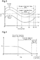
- the relationship between a stopping angle of the crankshaft 10a of the engine 10 being in the ideal state and a starting torque required to restart the engine 10, which has been stopped, is stored in the memory section of the electronic control unit 30. As shown in Figs. 2 and 3 , the relationship between the stopping angle of the crankshaft 10a and the starting torque of the engine 10 repeatedly changes every 180 CA.
- the starting torque of the engine 10 gradually becomes greater in proportion to increase from 0 CA of the stopping angle of the crankshaft 10a, and reaches its largest value at a predetermined stopping angle.
- the stopping angle of the crankshaft 10a at which the starting torque is maximized is, for example, near the crank angle CA at which the intake valve of a cylinder that is in a compression stroke when the engine 10 is stopped is closed.
- the starting torque of the engine 10 gradually becomes smaller in proportion to increase in the stopping angle of the crankshaft 10a, and becomes the minimum starting torque Ts at a predetermined stopping angle.
- the stopping angle of the crankshaft 10a at which the starting torque becomes the minimum starting torque Ts is, for example, slightly before the crank angle CA at which the exhaust valve of a cylinder that is in an expansion stroke when the engine 10 is stopped is opened. Thereafter, the starting torque of the engine 10 gradually becomes greater in proportion to an approach to 180 CA of the stopping angle of the crankshaft 10a.
- the relationship between the stopping angle of the crankshaft 10a being in the ideal state and a starting torque is pre-calculated by performing tests, simulations, and the like.
- the electronic control unit 30 calculates the starting torque required to restart the engine on the basis of the fuel injection amount Qf of the engine 10 or on the basis of the relationship between the stopping angle of the crankshaft 10a and the starting torque of the engine 10. In other words, the electronic control unit 30 functions as a starting-torque calculating section 30e.
- Specified time X1 which is to calculate an in-cylinder negative pressure period in which the pressure in a cylinder of the engine 10 is negative pressure relative to the atmospheric pressure after starting the automatic stop of the engine 10, is stored in the memory section of the electronic control unit 30.
- fresh intake air is not supplied into the cylinder of the engine 10 after a point in time t1, at which the automatic stop of the engine 10 is started so that fuel injection is stopped and at which the throttle valve is closed.
- the crankshaft 10a continues turning for a while because of inertia, and the gas in the cylinder is discharged as exhaust gas. Therefore, when the automatic stop of the engine 10 is started, the pressure in the cylinder becomes negative pressure relative to the atmospheric pressure.
- a period of time from the point in time t2, at which the rotation of the crankshaft 10a is completely stopped so that the engine rotation speed Ne of the engine 10 reaches zero until the pressure in the cylinder becomes equal to the atmospheric pressure is stored in the memory section of the electronic control unit 30 as the specified time X1.
- a point in time at which the specified time X1 has elapsed from the point in time t2, at which the engine rotation speed Ne of the engine 10 reaches zero is a cranking time limit t3.
- the specified time X1 (cranking time limit t3) is appropriately determined in accordance with the specifications of the engine 10, the specifications of the motor generator 20, and a combination of the engine 10 and the motor generator 20.
- the specified time X1 is pre-calculated by performing tests, simulations, and the like, and is, for example, several seconds.
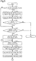
- step S11 the electronic control unit 30 determines whether the engine 10 is in idle operation. In detail, the electronic control unit 30 determines that the engine 10 is in idle operation when satisfying the condition that the engine rotation speed Ne of the engine 10 is lower than or equal to a predetermined rotation speed, the condition that the coolant temperature THW is higher than or equal to a predetermined temperature, the condition that the state of charge of the high-voltage battery 22 is higher than or equal to a predetermined value, the condition that the state of charge of the low-voltage battery 24 is higher than or equal to a predetermined value, the condition that the load of a non-electric auxiliary devices (e.g., air-conditioning compressor) drivably connected to the crankshaft 10a is smaller than or equal to a predetermined value, and the like.
- a non-electric auxiliary devices e.g., air-conditioning compressor
- step S11 If the electronic control unit 30 determines that the engine 10 is not in idle operation (NO in step S11), the process of the electronic control unit 30 skips step S12 to step S14 described later, and shifts to step S15. If the electronic control unit 30 determines that the engine 10 is in idle operation (YES in step S11), the process of the electronic control unit 30 shifts to step S12.
- step S12 based on the fuel injection amount Qf of the engine 10 when step S12 is performed, the electronic control unit 30 calculates the minimum starting torque Ts required to restart the engine 10 if the engine 10 is automatically stopped.
- the relationship between the stopping angle of the crankshaft 10a of the engine 10 that is in the ideal state and the starting torque required to restart the engine 10, which has been stopped, is stored in the memory section of the electronic control unit 30, and the minimum starting torque Ts1 is also pre-stored therein.
- the fuel injection amount required to idle the engine 10 being in the ideal state is stored in the memory section of the electronic control unit 30.
- the minimum starting torque Ts required to restart the engine 10 becomes greater than the minimum starting torque Ts1 in the ideal state as shown in Fig. 3 (shown in Fig. 3 as the minimum starting torques Ts2 and Ts3). Additionally, the fuel injection amount required to idle the engine 10 also becomes greater. Additionally, there is a positive correlation between the increment of the minimum starting torque Ts and the increment of the fuel injection amount required to idle the engine 10.
- the electronic control unit 30 calculates the minimum starting torque Ts such that the greater the excess of the fuel injection amount Qf of the engine 10 when the step S12 is performed in relation to the pre-stored fuel injection amount, the greater becomes the excess of the minimum starting torque Ts in relation to the pre-stored minimum starting torque Ts1 in the ideal state. After calculating the minimum starting torque Ts, the process of the electronic control unit 30 shifts to step S13.
- step S13 the electronic control unit 30 calculates an available torque Tmg of the motor generator 20 on the basis of the state information IM sent from the sensor section 20b of the motor generator 20 and the state information IHb sent from the sensor section 22a of the high-voltage battery 22.
- the electronic control unit 30 based on the state information IM, the electronic control unit 30 identifies the relationship between the rotation speed of the output shaft 20a of the motor generator 20 and the input current. For example, the available torque Tmg calculated by the electronic control unit 30 becomes smaller in proportion to a decrease in the rotation speed of the output shaft 20a for a certain input current.
- the electronic control unit 30 calculates the state of charge of the high-voltage battery 22.
- the available torque Tmg calculated by the electronic control unit 30 becomes smaller in proportion to a decrease in the state of charge. After calculating the available torque Tmg, the process of the electronic control unit 30 shifts to step S14.
- step S14 the electronic control unit 30 determines whether the value obtained by subtracting the minimum starting torque Ts from the available torque Tmg is greater than or equal to a threshold value Tx. Even if a calculating error in the available torque Tmg or in the minimum starting torque Ts occurs, the threshold value Tx is pre-set to a positive value so that the electronic control unit 30 can determine that the available torque Tmg is greater than the minimum starting torque Ts. If the electronic control unit 30 determines that the value obtained by subtracting the minimum starting torque Ts from the available torque Tmg is less than the threshold value Tx (NO in step S14), the series of steps of the automatic-stop restart process are ended.
- step S14 If the electronic control unit 30 determines that the value obtained by subtracting the minimum starting torque Ts from the available torque Tmg is greater than or equal to the threshold value Tx (YES in step S14), the process of the electronic control unit 30 shifts to step S15.
- step S15 the electronic control unit 30 determines whether all conditions to automatically stop the engine 10 are satisfied.
- the conditions to automatically stop the engine 10 include the condition that the vehicle speed SP detected by the vehicle speed sensor 32 is lower than or equal to a predetermined speed, the condition that the engine rotation speed Ne of the engine 10 is lower than or equal to a predetermined rotation speed, the condition that the accelerator pedal of the vehicle is not depressed, the condition that the load of a non-electric auxiliary device drivably connected to the crankshaft 10a is smaller or equal to a predetermined value, the condition that the state of charge of the high-voltage battery 22 is higher than or equal to a certain value, the condition that the state of charge of the low-voltage battery 24 is higher than or equal to a certain value, and the like.
- step S15 If the electronic control unit 30 determines that at least one of the conditions to automatically stop the engine 10 is not satisfied (NO in step S15), the series of steps of the automatic-stop restart process are ended. In other words, in this case, the engine 10 is not automatically stopped. If the electronic control unit 30 determines that all conditions to automatically stop the engine 10 are satisfied (YES in step S15), the process of the electronic control unit 30 shifts to step S16.
- step S16 the electronic control unit 30 outputs a manipulation signal MSen to the engine 10, and, as a result, fuel injection in the engine 10 is stopped, and the throttle valve is closed. In other words, the electronic control unit 30 starts an automatic stop of the engine 10. After step S16 is started, the engine 10 does not operate, and therefore step S11 is never started even if a predetermined control period has elapsed. After step S16 is performed, the process of the electronic control unit 30 shifts to step S17.
- step S17 the electronic control unit 30 outputs a manipulation signal MSmg to the motor generator 20, and applies torque to the motor generator 20 or to the crankshaft 10a, and, as a result, the stopping angle of the crankshaft 10a is adjusted.
- the behavior of the crankshaft 10a displayed when the engine 10 is stopped varies because of a slight time-dependent change of the engine 10, a slight change in the external environment, and the like. Therefore, in some cases, the stopping angle at which stopping actually occurs deviates about several degrees to about tens of degrees from the targeted stopping angle even if the stopping angle of the crankshaft 10a is adjusted as described above.
- step S17 the process of the electronic control unit 30 shifts to step S18.
- step S18 based on the crank angle CA detected by the crank angle sensor 31, the electronic control unit 30 calculates the absolute value of the amount of decrease of the engine rotation speed Ne of the engine 10 per unit time as a change amount ⁇ Ne. Thereafter, based on the calculated change amount ⁇ Ne, the electronic control unit 30 re-calculates the minimum starting torque Ts. In detail, the electronic control unit 30 calculates the minimum starting torque Ts as a greater value in proportion to an increase in the change amount ⁇ Ne (in proportion to an increase in the reduced speed of the engine rotation speed Ne). In step S19 subsequent to step S18, the electronic control unit 30 calculates the available torque Tmg of the motor generator 20. The calculation method of the available torque Tmg in step S19 is the same as the calculation method described in step S13. After calculating the available torque Tmg, the process of the electronic control unit 30 shifts to step S20.
- step S20 based on the minimum starting torque Ts calculated in step S18 and based on the available torque Tmg calculated in step S19, the electronic control unit 30 calculates the stopping-angle range of the crank angle CA, in which the engine 10 can be restarted by cranking by means of the motor generator 20, as an allowable crank-angle range CAa.
- the electronic control unit 30 calculates the difference between the minimum starting torque Ts1 in the ideal state, which is stored in the memory section, and the minimum starting torque Ts calculated in step S18.
- the electronic control unit 30 calculates a value obtained by translating the relationship between the stopping angle of the crankshaft 10a and the starting torque in the ideal state so that the torque becomes greater in proportion to the aforementioned difference as the relationship between the stopping angle of the crankshaft 10a and the starting torque when step S20 is performed. Furthermore, the electronic control unit 30 compares the relationship between the stopping angle of the crankshaft 10a and the starting torque calculated as above with the available torque Tmg, and calculates a range in which the starting torque becomes smaller than or equal to the available torque Tmg as an allowable crank-angle range CAa. Thereafter, the process of the electronic control unit 30 shifts to step S21 shown in Fig. 6 .
- step S21 the electronic control unit 30 determines whether the allowable crank-angle range CAa calculated in step S20 is larger than a predetermined specified range CAx.
- the specified range CAx is fixed in view of detection errors of the crank angle sensor 31 or the like, and is, for example, several degrees to tens of degrees.
- step S21 If the electronic control unit 30 determines that the allowable crank-angle range CAa is smaller than or equal to the specified range CAx (NO in step S21), the process of the electronic control unit 30 shifts to step S22.
- step S22 the electronic control unit 30 allows the motor generator 20 to function as a motor, and cranks the engine 10 (rotates the crankshaft 10a) by outputting a manipulation signal MSmg to the motor generator 20 not later than the cranking time limit t3.
- each process step is performed in units of several milliseconds to several hundred milliseconds at the longest.
- approximately one second to several seconds are taken from the start of the automatic stop of the engine 10 to the complete stop of the crankshaft 10a. Therefore, when the process reaches step S22 through step S21, the crankshaft 10a has not yet been stopped or, alternatively, has just been stopped.
- the specified time X1 is set to several seconds.
- step S22 is performed, and, as a result, the engine 10 is reliably cranked not later than the cranking time limit t3.
- step S23 subsequent thereto the electronic control unit 30 outputs a manipulation signal MSen to the engine 10, and, as a result, fuel injection is resumed in the engine 10.
- the throttle valve is also opened in response to the resumption of the fuel injection.
- the series of steps of the automatic-stop restart process are ended. In this case, the engine 10 is restarted before the crankshaft 10a is completely stopped although the automatic stop of the engine 10 is started.
- step S21 determines in step S21 that the allowable crank-angle range CAa is larger than the specified range CAx (YES in step S21)
- the process of the electronic control unit 30 shifts to step S24.
- step S24 the electronic control unit 30 waits for the crankshaft 10a to be stopped. Thereafter, the crank angle CA when the crankshaft 10a is stopped is detected as a stopping angle CAs. If the stopping angle CAs has been detected (YES in step S24), the process of the electronic control unit 30 shifts to step S25.
- step S25 the electronic control unit 30 compares the stopping angle CAs detected in step S24 with the allowable crank-angle range CAa calculated in step S20. Thereafter, the electronic control unit 30 determines whether the stopping angle CAs falls within the allowable crank-angle range CAa. If the electronic control unit 30 determines that the stopping angle CAs falls within the allowable crank-angle range CAa (YES in step S25), the process of the electronic control unit 30 shifts to step S26.
- step S26 the electronic control unit 30 determines whether there is a request to restart the engine 10, which has been automatically stopped.
- a request to restart the engine 10 is made on account of the fact that at least any one of the aforementioned conditions for automatically stopping the engine 10 is no longer satisfied. If the electronic control unit 30 determines that there is not a request to restart the engine 10 (NO in step S26), the electronic control unit 30 performs step S26 again. In other words, the electronic control unit 30 waits until a request to restart the engine 10 is made. On the other hand, if the electronic control unit 30 determines that there is a request to restart the engine 10 (YES in step S26), the process of the electronic control unit 30 shifts to step S27.
- step S27 the electronic control unit 30 allows the motor generator 20 to function as a motor, and cranks the engine 10 (rotates the crankshaft 10a) by outputting a manipulation signal MSmg to the motor generator 20.
- the electronic control unit 30 outputs a manipulation signal MSen to the engine 10, and, as a result, fuel injection is resumed in the engine 10, and the throttle valve is opened.
- the electronic control unit 30 restarts the engine 10, which has been automatically stopped. Thereafter, the series of steps of the automatic-stop restart process are ended.
- step S24 if the stopping angle CAs cannot be detected in step S24 (NO in step S24), the process of the electronic control unit 30 shifts to step S28.
- a case in which a signal from the crank angle sensor 31 is lost because the crank angle sensor 31 is out of order or a case in which a noticeably abnormal value is shown because noises are superimposed on the signal emitted from the crank angle sensor 31 can be assumed as a situation in which the stopping angle CAs cannot be calculated.
- step S25 determines in step S25 that the stopping angle CAs is outside the allowable crank-angle range CAa, (NO in step S25), the process of the electronic control unit 30 shifts to step S28.
- step S28 the electronic control unit 30 allows the motor generator 20 to function as a motor, and cranks the engine 10 by outputting a manipulation signal MSmg to the motor generator 20 not later than the cranking time limit t3.
- step S28 is performed without waiting time subsequent to step S24 or subsequent to step S25. Additionally, each process step is performed in units of several milliseconds to several hundred milliseconds at the longest. On the other hand, the specified time X1 is set to several seconds. Therefore, in the present embodiment, step S28 is performed, and, as a result, the engine 10 is reliably cranked not later than the cranking time limit t3. Subsequent to step S28, the process of the electronic control unit 30 shifts to step S29.
- step S29 the electronic control unit 30 determines whether there is a request to restart the engine 10, which has been automatically stopped. This determination content is the same as in the process performed in step S26. If the electronic control unit 30 determines that there is a request to restart the engine 10 (YES in step S29), the process of the electronic control unit 30 shifts to step S30.
- step S30 the electronic control unit 30 outputs a manipulation signal MSen to the engine 10, and, as a result, fuel injection is resumed in the engine 10.
- the throttle valve is also opened in response to the resumption of the fuel injection.
- the series of steps of the automatic-stop restart process are ended. In this case, the engine 10 is restarted in a state in which the crankshaft 10a is rotated by the motor generator 20 although the automatic stop of the engine 10 is executed.
- step S31 the electronic control unit 30 determines whether negative pressure can be generated in each cylinder of the engine 10 by allowing the motor generator 20 to crank the engine 10. In detail, the electronic control unit 30 determines that negative pressure can be generated if the state of charge of the high-voltage battery 22 is higher than or equal to a predetermined certain value. If the electronic control unit 30 determines that negative pressure cannot be generated, the process of the electronic control unit 30 shifts to step S30, and the engine 10 is restarted. In other words, in this case, the engine 10 is restarted regardless of the presence or absence of a request to restart the engine 10.
- step S31 determines in step S31 that negative pressure can be generated (YES in step S31)
- step S32 the cranking of the engine 10 by means of the motor generator 20, which has been started in step S28 mentioned above, is continuously performed. Thereafter, the process of the electronic control unit 30 shifts to step S33.
- step S33 the electronic control unit 30 determines whether a negative-pressure state relative to the atmospheric pressure has been regenerated in each cylinder of the engine 10.
- the electronic control unit 30 determines whether a specified period of time has elapsed after starting the cranking of the engine 10 by means of the motor generator 20 in step S28.
- the specified period is defined as a period of time from when the engine 10 is cranked by the motor generator 20 until when the crankshaft 10a rotates by a certain angle. This certain angle is, for example, several hundred to several thousand degrees (equal to several rotations of the crankshaft 10a).
- step S33 the electronic control unit 30 determines that negative pressure has not yet been generated (NO in step S33), and the process of the electronic control unit 30 returns to step S31.
- the electronic control unit 30 determines that negative pressure has been generated (YES in step S33), and the process of the electronic control unit 30 shifts to step S17 shown in Fig. 5 . Thereafter, the electronic control unit 30 re-performs the process of step S17 and the steps subsequent to step S17.
- the motor generator 20 is generally designed such that the available torque Tmg1 of the motor generator 20 exceeds the starting torque regardless of the stopping angle CAs of the crankshaft 10a when deterioration has not occurred in the output characteristics of the motor generator 20 and when the state of charge of the high-voltage battery 22, which supplies electric power to the motor generator 20, is sufficient (for example, not less than 50%) as shown in Fig. 2 .
- the available torque Tmg of the motor generator 20 is lowered to a smaller available torque Tmg3.
- the difference between the available torque Tmg3 and the minimum starting torque Ts becomes even smaller.
- the available torque Tmg3 exceeds the starting torque only within the allowable crank-angle range CAa2 of the stopping angle A3 to the stopping angle A4, and the allowable crank-angle range CAa becomes even narrower.
- the starting torque becomes greater than the starting torque in the ideal state if deposits accumulate on various parts, such as cylinders and pistons of the engine 10, so that the frictional resistance becomes greater as shown in Fig. 3 .
- the minimum starting torque Ts of the engine 10 increases from the minimum starting torque Ts1 in the ideal state in proportion to an increase in the amount of accumulation of deposits as shown by the minimum starting torque Ts2 and by the minimum starting torque Ts3.
- the difference between the available torque Tmg and the minimum starting torque Ts becomes smaller.
- the allowable crank-angle range CAa becomes narrower as shown by the allowable crank-angle range CAa3 of a stopping angle B1 to a stopping angle B2 and by the allowable crank-angle range CAa4 of a stopping angle B3 to a stopping angle B4.
- the engine 10 is not automatically stopped if the value obtained by subtracting the minimum starting torque Ts from the available torque Tmg is less than the threshold value Tx (see step S14 in Fig. 5 ).
- the automatic stop of the engine 10 is prohibited if the allowable crank-angle range CAa is extremely narrow or does not exist. Therefore, the automatic stop of the engine 10 does not occur in spite of the fact that the engine 10 cannot be cranked by the motor generator 20.
- the engine 10 can be cranked by the motor generator 20 if the stopping angle CAs of the crankshaft 10a when the engine 10 is stopped is within the allowable crank-angle range CAa.
- the allowable crank-angle range CAa is extremely narrow, the possibility that the stopping angle CAs will fall within the allowable crank-angle range CAa is low. Additionally, a certain error might occur when the stopping angle CAs is detected as described above.
- the engine 10 is cranked by the motor generator 20 if the allowable crank-angle range CAa is smaller than or equal to the specified range CAx (see step S21 and step S22 in Fig. 6 ). Therefore, the crankshaft 10a is restrained from being stopped at a stopping angle CAs at which the engine 10 cannot be cranked by the motor generator 20.
- the stopping angle CAs it is determined whether the stopping angle CAs falls within the allowable crank-angle range CAa when the allowable crank-angle range CAa is wider than the specified range CAx. If the stopping angle CAs is outside the allowable crank-angle range CAa, it becomes impossible to start the cranking of the engine 10 by means of the motor generator 20.
- the engine 10 is cranked by the motor generator 20 before an in-cylinder negative pressure period elapses from when the automatic stop of the engine 10 is started. If the engine 10 is cranked in this way, the crankshaft 10a is never stopped at a stopping angle CAs at which restart cannot be performed by the motor generator 20. Therefore, time is not taken to adjust the stopping position of the crankshaft 10a. As a result, if there is a request to restart the engine 10, it is possible to swiftly restart the engine 10.
- the pressure in the cylinder of the engine 10 is negative pressure relative to the atmospheric pressure. Therefore, it is possible to rotate the crankshaft 10a by using the negative pressure of the inside of the cylinder. Therefore, if the period is within this in-cylinder negative pressure period, it is possible to start the cranking of the engine 10 by means of the motor generator 20 even if the stopping angle CAs of the crankshaft 10a is outside the allowable crank-angle range CAa.
- the minimum starting torque Ts is calculated on the basis of the fuel injection amount Qf before starting the automatic stop of the engine 10 (prior to step S16).
- the minimum starting torque Ts is calculated by using a change amount ⁇ Ne per unit time of the engine rotation speed Ne.
- the change amount ⁇ Ne of the engine rotation speed Ne more directly reflects friction or the like between the piston and the cylinder in the engine 10 in comparison with the fuel injection amount Qf.
- the change amount ⁇ Ne of the engine rotation speed Ne has a high correlation with respect to the starting torque. Grounding on the thus characterized change amount ⁇ Ne of the engine rotation speed Ne makes it possible to more accurately calculate the allowable crank-angle range CAa.
- cranking of the engine 10 by means of the motor generator 20 is started within the in-cylinder negative pressure period of the engine 10
- cranking is continuously performed, and negative pressure is re-generated in the cylinder of the engine 10 if there is room in the state of charge of the high-voltage battery 22.
- negative pressure is re-generated in the cylinder of the engine 10 by continuously performing cranking for or beyond the specified time, the cranking is stopped. Therefore, the state of charge of the high-voltage battery 22 is restrained from being excessively lowered in order for the motor generator 20 to continuously crank the engine 10.
- negative pressure is re-generated as described above, and therefore it is possible to again create a situation in which the engine 10 has been automatically stopped.
- the thus performed control makes it possible to again perform the series of steps of the process subsequent to the start of the automatic stop of the engine 10.
- the present embodiment may be modified as follows.
- the present embodiment and the following modifications can be combined as long as the combined modifications remain technically consistent with each other.
- the mode in which the engine 10 and the motor generator 20 are drivably connected together is not limited to the aforementioned embodiment. Additionally, a decelerating mechanism composed of, for example, a plurality of gears, a clutch that connects/disconnects a driving-force transmission path, and the like, in addition to the first pulley 12, the transmission belt 13, and the second pulley 14, may be interposed between the engine 10 and the motor generator 20.
- the output voltage of the high-voltage battery 22 and that of the low-voltage battery 24 do not matter. Additionally, the output voltage of the low-voltage battery 24 is not necessarily required to be lower than the output voltage of the high-voltage battery 22, and both output voltages may be equal to each other.
- the kind of the high-voltage battery 22 and that of the low-voltage battery 24 are not limited to the examples of the aforementioned embodiment.
- a nickel hydrogen battery, a NAS battery, an all solid-state battery, and the like, besides a lithium-ion battery and a lead-acid battery, may be employed as the high-voltage battery 22 and as the low-voltage battery 24.
- a motor generator that chiefly assists the traveling torque of the engine 10 and a motor generator that chiefly generates electricity by torque from the engine 10 may be provided separately. In this case, it is recommended to apply the automatic-stop restart process of the aforementioned embodiment onto the motor generator that assists the traveling torque of the engine 10.
- the stopping angle CAs of the crankshaft 10a may be a predictive stopping angle CAs without being limited to the detection of the crank angle CA when the crankshaft 10a is actually stopped.
- the predictive stopping angle CAs may be a stopping angle CAs detected by the stopping-angle detection section 30a of the electronic control unit 30.
- step S21 to step S23 in the aforementioned embodiment may be omitted, and it may be determined whether the stopping angle CAs falls within the allowable crank-angle range CAa regardless of the size of the allowable crank-angle range CAa (step S25 may be performed). If high accuracy can be expected as the detection accuracy of the stopping angle CAs, it might be preferable to reduce a processing burden of the electronic control unit 30 by omitting the process of step S21 to step S23 in some cases.
- step S31 in the aforementioned embodiment may be omitted, and the cranking of the engine 10 by means of the motor generator 20 may be continuously performed regardless of the state of charge of the high-voltage battery 22.
- the period of time of the automatic stop of the engine 10 assumed in the aforementioned embodiment is approximately several minutes to ten-odd minutes at the longest.
- the state of charge of the high-voltage battery 22 is controlled so as to fall within a certain range (e.g., 40% to 70%) while the engine 10 is operating.
- the maximum state of charge (full state of charge) of the high-voltage battery 22 is suitably large, it is possible to restrain the state of charge of the high-voltage battery 22 from being excessively lowered even if the cranking of the engine 10 by means of the motor generator 20 is continuously performed. Additionally, if an electric auxiliary device driven by the high-voltage battery 22 does not exert a great influence on vehicle traveling even if the state of charge of the high-voltage battery 22 is excessively lowered, a problem will not arise even if the cranking of the engine 10 by means of the motor generator 20 is continuously performed.
- the threshold value Tx can be appropriately changed if the threshold value Tx is a zero or more. If the threshold value Tx is set to a large value, the possibility that an actual stopping angle of the crankshaft 10a will be placed outside the allowable crank-angle range CAa will be lowered in spite of the fact that the determination of step S14 is affirmative. On the other hand, if the threshold value Tx is set to a small value, the opportunity of enabling the automatic stop of the engine 10 will be increased.
- step S14 of the aforementioned embodiment it is permissible to subtract the maximum value (maximum starting torque) of the starting torque of the engine 10 from the available torque Tmg of the motor generator 20 and to make a comparison between the resultant subtraction value and another threshold value differing from the threshold value Tx.
- the starting torque is translated toward the high-torque side because of accumulation of deposits and the like in the engine 10 as shown in Fig. 3 . Therefore, the minimum starting torque and the maximum starting torque of the engine 10 vary in conjunction with each other. Therefore, it is also possible to make an indirect comparison between the minimum starting torque Ts and the threshold value Tx by comparing the value obtained by subtracting the maximum starting torque from the available torque Tmg with the threshold value.
- the minimum starting torque may be calculated on the basis of the fuel injection amount Qf when the engine 10 is in a predetermined drive state exclusive of being in idle operation, instead of calculating the minimum starting torque Ts on the basis of the fuel injection amount Qf when the engine 10 is in idle operation.
- the predetermined drive state includes a state in which parameters, such as the opening degree of the throttle valve and the engine rotation speed Ne in the engine 10, that affect a combustion state in the engine 10 are made constant. Based on the fuel injection amount Qf in this state, the minimum starting torque Ts can also be calculated.
- step S11 to step S14 may be omitted.
- the omission of the process of step S11 to step S14 will not cause a problem if it is unlikely that the available torque Tmg will become smaller than the minimum starting torque Ts even if the available torque Tmg of the motor generator 20 or the starting torque of the engine 10 varies somewhat, because the difference between the available torque Tmg of the motor generator 20 and the starting torque of the engine 10 is large.
- the calculation method of the minimum starting torque Ts is not limited to the example of the aforementioned embodiment.
- the engine rotation speed Ne of the engine 10 is set to a predetermined rotation speed by applying torque to the crankshaft 10a from the motor generator 20 in a state in which the fuel injection amount in the engine 10 is constant without being changed. If the friction in the engine 10 is large and therefore the minimum starting torque Ts is large, the output torque of the motor generator 20 when a control operation is performed as above also becomes large. Therefore, it is also possible to calculate the minimum starting torque Ts based on the output voltage or the output current of the motor generator 20 at this time.
- any calculation method of the allowable crank-angle range CAa can be employed. For example, it is permissible to divert the minimum starting torque Ts calculated in step S12 and to calculate the allowable crank-angle range CAa on the basis of the resultant diversion value, instead of calculating the minimum starting torque Ts in step S18 on the basis of the change amount ⁇ Ne of the engine rotation speed Ne.
- the allowable crank-angle range CAa may be calculated on the basis of an integration value of vehicle traveling distance. It is conceivable that the amount of accumulation of deposits in the engine 10 or deterioration in the output characteristics of the motor generator 20 has a correlation with the integration value of vehicle traveling distance. Therefore, a certain degree of accuracy can be expected even when the allowable crank-angle range CAa is calculated on the basis of the integration value of traveling distance.
- the allowable crank-angle range CAa may fall within a predetermined fixed range if the process of step S21 to step S23 is omitted.
- the allowable crank-angle range CAa is not necessarily required to be calculated.
- a relational expression or the like in which the minimum starting torque Ts of the engine 10, the available torque Tmg of the motor generator 20, and the stopping angle CAs of the crankshaft 10a are defined as variables is pre-stored in the memory section of the electronic control unit 30. Thereafter, based on a value derived by this relational expression, it may be determined whether the stopping angle CAs is within or outside the stopping-angle range of the crank angle in which the engine 10 can be cranked and restarted by the motor generator 20.
- the in-cylinder negative pressure period may be fixed as a specified time from the point in time t1, at which fuel injection is stopped and the throttle valve is closed in the engine 10, instead of fixing the in-cylinder negative pressure period on the basis of the specified time X1, from point in time t2 at which the crankshaft 10a is stopped.
- the specified time X1 is set to a period of time elapsing from the point in time t2 at which the crankshaft 10a is stopped in the aforementioned embodiment, the present invention is not limited to this.
- the specified time X1 may be defined as a period of time after the rotation speed of the crankshaft 10a (the engine rotation speed Ne) has reached a predetermined rotation speed.
- the specified time X1 is set to a period of time until the pressure in the cylinder of the engine 10 becomes equal to the atmospheric pressure in the aforementioned embodiment, the present invention is not limited to this.
- the specified time X1 may be set to a period of time until the pressure in the cylinder of the engine 10 becomes lower by prescribed pressure than the atmospheric pressure.
- the engine 10 can be reliably cranked by setting the specified time X1 as in this modification.
- the specified period in which the pressure in the cylinder of the engine 10 again becomes negative pressure is defined as a period of time until the crankshaft 10a is rotated by a certain angle in the aforementioned embodiment, this may be set defined by time. If the specified period is defined by time, it is preferable to employ, for example, approximately several hundred milliseconds to several seconds.
- the cranking of the engine 10 by means of the motor generator 20 can be omitted. For example, if it is immediately after starting the automatic stop of the engine 10, the crankshaft 10a is still being rotated. If it is a period of time in which the crankshaft 10a has not yet been completely stopped as above, there is room for the engine 10 to be restarted only by resuming fuel injection without cranking.
- step S24 If it is determined that the allowable crank-angle range CAa is larger than the specified range CAx in step S21 of the aforementioned embodiment, the process of step S24 to step S33 subsequent thereto may be omitted. In this case, if it is determined that the allowable crank-angle range CAa is larger than the specified range CAx, it is recommended to stop the crankshaft 10a as it is and to restart the engine 10 in accordance with a restart request.
- the engine 10 there is a configuration, such as an electric intake valve, that is capable of controlling the opening degree (amount of lift) of the intake valve, which differs from the revolution of the crankshaft 10a. If the engine 10 is a thus configured engine, it is also possible to limit the intake air amount into the engine 10 by reducing the opening degree of the intake valve, instead of or in addition to closing the throttle valve when the engine 10 is automatically stopped.
- the vehicle may be allowed to travel by means of torque from the motor generator 20, instead of resuming fuel injection after the engine 10 is cranked by the motor generator 20.
- the electronic control unit 30 is not limited to one that performs software processing on all processes executed by itself.
- the electronic control unit 30 may include at least part of the processes executed by the software in the present embodiment as one that is executed by hardware circuits dedicated to execution of these processes (such as ASIC). That is, the electronic control unit 30 may be modified as long as it has any one of the following configurations (a) to (c).
- a plurality of software processing circuits each including a processor and a program storage device and a plurality of dedicated hardware circuits may be provided. That is, the above processes may be executed in any manner as long as the processes are executed by processing circuitry that includes at least one of a set of one or more software processing circuits and a set of one or more dedicated hardware circuits.
Landscapes
- Engineering & Computer Science (AREA)
- Chemical & Material Sciences (AREA)
- Combustion & Propulsion (AREA)
- Mechanical Engineering (AREA)
- General Engineering & Computer Science (AREA)
- Transportation (AREA)
- Automation & Control Theory (AREA)
- Control Of Vehicle Engines Or Engines For Specific Uses (AREA)
- Hybrid Electric Vehicles (AREA)
- Electric Propulsion And Braking For Vehicles (AREA)
- Combined Controls Of Internal Combustion Engines (AREA)
Applications Claiming Priority (1)
| Application Number | Priority Date | Filing Date | Title |
|---|---|---|---|
| JP2018076237A JP7073870B2 (ja) | 2018-04-11 | 2018-04-11 | 始動制御装置 |
Publications (2)
| Publication Number | Publication Date |
|---|---|
| EP3553300A1 true EP3553300A1 (de) | 2019-10-16 |
| EP3553300B1 EP3553300B1 (de) | 2024-04-17 |
Family
ID=65818281
Family Applications (1)
| Application Number | Title | Priority Date | Filing Date |
|---|---|---|---|
| EP19163369.2A Active EP3553300B1 (de) | 2018-04-11 | 2019-03-18 | Startsteuergerät und startsteuerungsverfahren |
Country Status (6)
| Country | Link |
|---|---|
| US (1) | US10696293B2 (de) |
| EP (1) | EP3553300B1 (de) |
| JP (1) | JP7073870B2 (de) |
| KR (1) | KR102195718B1 (de) |
| CN (1) | CN110356384B (de) |
| RU (1) | RU2707162C1 (de) |
Families Citing this family (10)
| Publication number | Priority date | Publication date | Assignee | Title |
|---|---|---|---|---|
| JP7474657B2 (ja) * | 2020-08-18 | 2024-04-25 | 株式会社Subaru | アイドリングストップ制御装置 |
| WO2022067619A1 (zh) * | 2020-09-30 | 2022-04-07 | 舍弗勒技术股份两合公司 | 混合动力汽车换档过程中的发动机启动控制方法及装置 |
| JP7647226B2 (ja) * | 2021-03-25 | 2025-03-18 | マツダ株式会社 | エンジンの始動制御装置 |
| US11661914B2 (en) * | 2021-06-07 | 2023-05-30 | Ford Global Technologies, Llc | Methods and system for starting an engine |
| JP7662450B2 (ja) * | 2021-08-06 | 2025-04-15 | トヨタ自動車株式会社 | 車両の制御装置 |
| JP7559741B2 (ja) * | 2021-12-02 | 2024-10-02 | トヨタ自動車株式会社 | 制御装置 |
| JP7513047B2 (ja) * | 2022-03-23 | 2024-07-09 | トヨタ自動車株式会社 | 車両の制御装置 |
| JP7601044B2 (ja) * | 2022-04-01 | 2024-12-17 | トヨタ自動車株式会社 | 車両の制御装置 |
| CN114810387B (zh) * | 2022-05-16 | 2023-04-07 | 中国第一汽车股份有限公司 | 发动机的控制方法与车载ecu |
| JP7771996B2 (ja) | 2023-01-11 | 2025-11-18 | トヨタ自動車株式会社 | 内燃機関の始動装置 |
Citations (4)
| Publication number | Priority date | Publication date | Assignee | Title |
|---|---|---|---|---|
| EP1588047A1 (de) * | 2003-01-27 | 2005-10-26 | Toyota Jidosha Kabushiki Kaisha | Steuervorrichtung für verbrennungsmotor |
| JP2013252725A (ja) | 2012-06-05 | 2013-12-19 | Nissan Motor Co Ltd | ハイブリッド車両のエンジン始動制御装置 |
| US20140172219A1 (en) * | 2011-07-28 | 2014-06-19 | Toyota Jidosha Kabushiki Kaisha | Engine stop control device for hybrid vehicle |
| US20170089314A1 (en) * | 2014-07-02 | 2017-03-30 | Cummins Inc. | Engine start/stop function management |
Family Cites Families (10)
| Publication number | Priority date | Publication date | Assignee | Title |
|---|---|---|---|---|
| JP3894272B2 (ja) | 2000-05-29 | 2007-03-14 | 三菱自動車工業株式会社 | ハイブリッド車 |
| JP3852389B2 (ja) * | 2002-09-30 | 2006-11-29 | マツダ株式会社 | エンジンの始動装置 |
| JP3794389B2 (ja) * | 2003-01-27 | 2006-07-05 | トヨタ自動車株式会社 | 内燃機関の停止制御装置 |
| JP4683304B2 (ja) | 2006-11-29 | 2011-05-18 | マツダ株式会社 | エンジン停止制御装置 |
| JP2010274739A (ja) | 2009-05-27 | 2010-12-09 | Toyota Motor Corp | 内燃機関装置およびハイブリッド車 |
| US9097200B2 (en) * | 2010-06-30 | 2015-08-04 | Mazda Motor Corporation | Starter and starting method of compression self-ignition engine |
| US9068546B2 (en) * | 2012-05-04 | 2015-06-30 | Ford Global Technologies, Llc | Methods and systems for engine cranking |
| US9322380B2 (en) * | 2012-05-04 | 2016-04-26 | Ford Global Technologies, Llc | Methods and systems for engine starting during a shift |
| US9261040B2 (en) * | 2013-03-14 | 2016-02-16 | Ford Global Technologies, Llc | Method for improving engine starting |
| JP2015033914A (ja) * | 2013-08-09 | 2015-02-19 | いすゞ自動車株式会社 | ハイブリッドシステム、ハイブリッド車両、及びハイブリッドシステムの動力伝達方法 |
-
2018
- 2018-04-11 JP JP2018076237A patent/JP7073870B2/ja active Active
-
2019
- 2019-03-18 EP EP19163369.2A patent/EP3553300B1/de active Active
- 2019-03-20 US US16/359,955 patent/US10696293B2/en active Active
- 2019-04-08 KR KR1020190040771A patent/KR102195718B1/ko active Active
- 2019-04-09 CN CN201910278925.5A patent/CN110356384B/zh active Active
- 2019-04-09 RU RU2019110487A patent/RU2707162C1/ru active
Patent Citations (4)
| Publication number | Priority date | Publication date | Assignee | Title |
|---|---|---|---|---|
| EP1588047A1 (de) * | 2003-01-27 | 2005-10-26 | Toyota Jidosha Kabushiki Kaisha | Steuervorrichtung für verbrennungsmotor |
| US20140172219A1 (en) * | 2011-07-28 | 2014-06-19 | Toyota Jidosha Kabushiki Kaisha | Engine stop control device for hybrid vehicle |
| JP2013252725A (ja) | 2012-06-05 | 2013-12-19 | Nissan Motor Co Ltd | ハイブリッド車両のエンジン始動制御装置 |
| US20170089314A1 (en) * | 2014-07-02 | 2017-03-30 | Cummins Inc. | Engine start/stop function management |
Also Published As
| Publication number | Publication date |
|---|---|
| KR102195718B1 (ko) | 2020-12-28 |
| KR20190118970A (ko) | 2019-10-21 |
| RU2707162C1 (ru) | 2019-11-22 |
| BR102019006357A2 (pt) | 2019-10-29 |
| JP7073870B2 (ja) | 2022-05-24 |
| CN110356384A (zh) | 2019-10-22 |
| CN110356384B (zh) | 2022-04-05 |
| US10696293B2 (en) | 2020-06-30 |
| US20190315339A1 (en) | 2019-10-17 |
| JP2019182239A (ja) | 2019-10-24 |
| EP3553300B1 (de) | 2024-04-17 |
Similar Documents
| Publication | Publication Date | Title |
|---|---|---|
| EP3553300B1 (de) | Startsteuergerät und startsteuerungsverfahren | |
| US9458813B2 (en) | Vehicle electric power supply apparatus | |
| CN110159440B (zh) | 车辆的发动机启动控制装置 | |
| WO2019026545A1 (ja) | トルク監視装置および内燃機関制御システム | |
| US20190226440A1 (en) | Driving system and driving method for vehicle | |
| US10557429B2 (en) | Engine control apparatus | |
| US20190242352A1 (en) | Engine control apparatus | |
| US20140222316A1 (en) | Control apparatus and control method for internal combustion engine | |
| JP6195870B2 (ja) | エンジン始動制御装置およびエンジン始動制御方法 | |
| US10655587B2 (en) | Engine stop/start control apparatus | |
| JP5578336B2 (ja) | ハイブリッド車両の制御装置 | |
| JP4075508B2 (ja) | 内燃機関の制御装置 | |
| EP2396530B1 (de) | Steuerung eines verbrennungsmotors | |
| JP2018084219A (ja) | 始動制御装置、始動装置及び始動制御システム | |
| JP6515786B2 (ja) | エンジンの始動制御装置 | |
| US7948240B2 (en) | Abnormality diagnosing apparatus for a glow plug | |
| JP2020128186A (ja) | ハイブリッドシステムの制御装置 | |
| JP7800456B2 (ja) | ハイブリッド車両の制御装置 | |
| BR102019006357B1 (pt) | Controlador de partida e método de controle de partida | |
| WO2015159876A1 (ja) | 車両用制御装置 | |
| JP7110718B2 (ja) | 内燃機関の始動制御装置 | |
| JP2017061883A (ja) | エンジン停止制御装置 | |
| JP5729258B2 (ja) | 車両の制御装置 | |
| KR20210152793A (ko) | Cvvt 장치 진단 방법 | |
| JP2019188869A (ja) | 車両のエンジン始動制御装置 |
Legal Events
| Date | Code | Title | Description |
|---|---|---|---|
| PUAI | Public reference made under article 153(3) epc to a published international application that has entered the european phase |
Free format text: ORIGINAL CODE: 0009012 |
|
| STAA | Information on the status of an ep patent application or granted ep patent |
Free format text: STATUS: REQUEST FOR EXAMINATION WAS MADE |
|
| 17P | Request for examination filed |
Effective date: 20190318 |
|
| AK | Designated contracting states |
Kind code of ref document: A1 Designated state(s): AL AT BE BG CH CY CZ DE DK EE ES FI FR GB GR HR HU IE IS IT LI LT LU LV MC MK MT NL NO PL PT RO RS SE SI SK SM TR |
|
| AX | Request for extension of the european patent |
Extension state: BA ME |
|
| GRAP | Despatch of communication of intention to grant a patent |
Free format text: ORIGINAL CODE: EPIDOSNIGR1 |
|
| STAA | Information on the status of an ep patent application or granted ep patent |
Free format text: STATUS: GRANT OF PATENT IS INTENDED |
|
| INTG | Intention to grant announced |
Effective date: 20201222 |
|
| GRAJ | Information related to disapproval of communication of intention to grant by the applicant or resumption of examination proceedings by the epo deleted |
Free format text: ORIGINAL CODE: EPIDOSDIGR1 |
|
| STAA | Information on the status of an ep patent application or granted ep patent |
Free format text: STATUS: REQUEST FOR EXAMINATION WAS MADE |
|
| INTC | Intention to grant announced (deleted) | ||
| RIN1 | Information on inventor provided before grant (corrected) |
Inventor name: SATO, HIROSHI Inventor name: OKUMURA, SHIN Inventor name: MURAKAMI, KOJI |
|
| STAA | Information on the status of an ep patent application or granted ep patent |
Free format text: STATUS: EXAMINATION IS IN PROGRESS |
|
| 17Q | First examination report despatched |
Effective date: 20210326 |
|
| GRAP | Despatch of communication of intention to grant a patent |
Free format text: ORIGINAL CODE: EPIDOSNIGR1 |
|
| STAA | Information on the status of an ep patent application or granted ep patent |
Free format text: STATUS: GRANT OF PATENT IS INTENDED |
|
| INTG | Intention to grant announced |
Effective date: 20240117 |
|
| GRAS | Grant fee paid |
Free format text: ORIGINAL CODE: EPIDOSNIGR3 |
|
| GRAA | (expected) grant |
Free format text: ORIGINAL CODE: 0009210 |
|
| STAA | Information on the status of an ep patent application or granted ep patent |
Free format text: STATUS: THE PATENT HAS BEEN GRANTED |
|
| AK | Designated contracting states |
Kind code of ref document: B1 Designated state(s): AL AT BE BG CH CY CZ DE DK EE ES FI FR GB GR HR HU IE IS IT LI LT LU LV MC MK MT NL NO PL PT RO RS SE SI SK SM TR |
|
| REG | Reference to a national code |
Ref country code: GB Ref legal event code: FG4D |
|
| REG | Reference to a national code |
Ref country code: CH Ref legal event code: EP |
|
| REG | Reference to a national code |
Ref country code: DE Ref legal event code: R096 Ref document number: 602019050314 Country of ref document: DE |
|
| REG | Reference to a national code |
Ref country code: IE Ref legal event code: FG4D |
|
| P01 | Opt-out of the competence of the unified patent court (upc) registered |
Effective date: 20240419 |
|
| REG | Reference to a national code |
Ref country code: LT Ref legal event code: MG9D |
|
| REG | Reference to a national code |
Ref country code: NL Ref legal event code: MP Effective date: 20240417 |
|
| REG | Reference to a national code |
Ref country code: DE Ref legal event code: R084 Ref document number: 602019050314 Country of ref document: DE |
|
| REG | Reference to a national code |
Ref country code: AT Ref legal event code: MK05 Ref document number: 1677462 Country of ref document: AT Kind code of ref document: T Effective date: 20240417 |
|
| PG25 | Lapsed in a contracting state [announced via postgrant information from national office to epo] |
Ref country code: NL Free format text: LAPSE BECAUSE OF FAILURE TO SUBMIT A TRANSLATION OF THE DESCRIPTION OR TO PAY THE FEE WITHIN THE PRESCRIBED TIME-LIMIT Effective date: 20240417 |
|
| PG25 | Lapsed in a contracting state [announced via postgrant information from national office to epo] |
Ref country code: NL Free format text: LAPSE BECAUSE OF FAILURE TO SUBMIT A TRANSLATION OF THE DESCRIPTION OR TO PAY THE FEE WITHIN THE PRESCRIBED TIME-LIMIT Effective date: 20240417 |
|
| PG25 | Lapsed in a contracting state [announced via postgrant information from national office to epo] |
Ref country code: IS Free format text: LAPSE BECAUSE OF FAILURE TO SUBMIT A TRANSLATION OF THE DESCRIPTION OR TO PAY THE FEE WITHIN THE PRESCRIBED TIME-LIMIT Effective date: 20240817 |
|
| PG25 | Lapsed in a contracting state [announced via postgrant information from national office to epo] |
Ref country code: BG Free format text: LAPSE BECAUSE OF FAILURE TO SUBMIT A TRANSLATION OF THE DESCRIPTION OR TO PAY THE FEE WITHIN THE PRESCRIBED TIME-LIMIT Effective date: 20240417 |
|
| PG25 | Lapsed in a contracting state [announced via postgrant information from national office to epo] |
Ref country code: HR Free format text: LAPSE BECAUSE OF FAILURE TO SUBMIT A TRANSLATION OF THE DESCRIPTION OR TO PAY THE FEE WITHIN THE PRESCRIBED TIME-LIMIT Effective date: 20240417 Ref country code: FI Free format text: LAPSE BECAUSE OF FAILURE TO SUBMIT A TRANSLATION OF THE DESCRIPTION OR TO PAY THE FEE WITHIN THE PRESCRIBED TIME-LIMIT Effective date: 20240417 |
|
| PG25 | Lapsed in a contracting state [announced via postgrant information from national office to epo] |
Ref country code: GR Free format text: LAPSE BECAUSE OF FAILURE TO SUBMIT A TRANSLATION OF THE DESCRIPTION OR TO PAY THE FEE WITHIN THE PRESCRIBED TIME-LIMIT Effective date: 20240718 |
|
| PG25 | Lapsed in a contracting state [announced via postgrant information from national office to epo] |
Ref country code: PT Free format text: LAPSE BECAUSE OF FAILURE TO SUBMIT A TRANSLATION OF THE DESCRIPTION OR TO PAY THE FEE WITHIN THE PRESCRIBED TIME-LIMIT Effective date: 20240819 |
|
| REG | Reference to a national code |
Ref country code: GB Ref legal event code: 746 Effective date: 20240920 |
|
| PG25 | Lapsed in a contracting state [announced via postgrant information from national office to epo] |
Ref country code: ES Free format text: LAPSE BECAUSE OF FAILURE TO SUBMIT A TRANSLATION OF THE DESCRIPTION OR TO PAY THE FEE WITHIN THE PRESCRIBED TIME-LIMIT Effective date: 20240417 |
|
| PG25 | Lapsed in a contracting state [announced via postgrant information from national office to epo] |
Ref country code: AT Free format text: LAPSE BECAUSE OF FAILURE TO SUBMIT A TRANSLATION OF THE DESCRIPTION OR TO PAY THE FEE WITHIN THE PRESCRIBED TIME-LIMIT Effective date: 20240417 |
|
| PG25 | Lapsed in a contracting state [announced via postgrant information from national office to epo] |
Ref country code: PL Free format text: LAPSE BECAUSE OF FAILURE TO SUBMIT A TRANSLATION OF THE DESCRIPTION OR TO PAY THE FEE WITHIN THE PRESCRIBED TIME-LIMIT Effective date: 20240417 |
|
| PG25 | Lapsed in a contracting state [announced via postgrant information from national office to epo] |
Ref country code: LV Free format text: LAPSE BECAUSE OF FAILURE TO SUBMIT A TRANSLATION OF THE DESCRIPTION OR TO PAY THE FEE WITHIN THE PRESCRIBED TIME-LIMIT Effective date: 20240417 |
|
| PG25 | Lapsed in a contracting state [announced via postgrant information from national office to epo] |
Ref country code: PT Free format text: LAPSE BECAUSE OF FAILURE TO SUBMIT A TRANSLATION OF THE DESCRIPTION OR TO PAY THE FEE WITHIN THE PRESCRIBED TIME-LIMIT Effective date: 20240819 Ref country code: PL Free format text: LAPSE BECAUSE OF FAILURE TO SUBMIT A TRANSLATION OF THE DESCRIPTION OR TO PAY THE FEE WITHIN THE PRESCRIBED TIME-LIMIT Effective date: 20240417 Ref country code: NO Free format text: LAPSE BECAUSE OF FAILURE TO SUBMIT A TRANSLATION OF THE DESCRIPTION OR TO PAY THE FEE WITHIN THE PRESCRIBED TIME-LIMIT Effective date: 20240717 Ref country code: LV Free format text: LAPSE BECAUSE OF FAILURE TO SUBMIT A TRANSLATION OF THE DESCRIPTION OR TO PAY THE FEE WITHIN THE PRESCRIBED TIME-LIMIT Effective date: 20240417 Ref country code: IS Free format text: LAPSE BECAUSE OF FAILURE TO SUBMIT A TRANSLATION OF THE DESCRIPTION OR TO PAY THE FEE WITHIN THE PRESCRIBED TIME-LIMIT Effective date: 20240817 Ref country code: HR Free format text: LAPSE BECAUSE OF FAILURE TO SUBMIT A TRANSLATION OF THE DESCRIPTION OR TO PAY THE FEE WITHIN THE PRESCRIBED TIME-LIMIT Effective date: 20240417 Ref country code: GR Free format text: LAPSE BECAUSE OF FAILURE TO SUBMIT A TRANSLATION OF THE DESCRIPTION OR TO PAY THE FEE WITHIN THE PRESCRIBED TIME-LIMIT Effective date: 20240718 Ref country code: FI Free format text: LAPSE BECAUSE OF FAILURE TO SUBMIT A TRANSLATION OF THE DESCRIPTION OR TO PAY THE FEE WITHIN THE PRESCRIBED TIME-LIMIT Effective date: 20240417 Ref country code: ES Free format text: LAPSE BECAUSE OF FAILURE TO SUBMIT A TRANSLATION OF THE DESCRIPTION OR TO PAY THE FEE WITHIN THE PRESCRIBED TIME-LIMIT Effective date: 20240417 Ref country code: BG Free format text: LAPSE BECAUSE OF FAILURE TO SUBMIT A TRANSLATION OF THE DESCRIPTION OR TO PAY THE FEE WITHIN THE PRESCRIBED TIME-LIMIT Effective date: 20240417 Ref country code: AT Free format text: LAPSE BECAUSE OF FAILURE TO SUBMIT A TRANSLATION OF THE DESCRIPTION OR TO PAY THE FEE WITHIN THE PRESCRIBED TIME-LIMIT Effective date: 20240417 Ref country code: RS Free format text: LAPSE BECAUSE OF FAILURE TO SUBMIT A TRANSLATION OF THE DESCRIPTION OR TO PAY THE FEE WITHIN THE PRESCRIBED TIME-LIMIT Effective date: 20240717 |
|
| PG25 | Lapsed in a contracting state [announced via postgrant information from national office to epo] |
Ref country code: DK Free format text: LAPSE BECAUSE OF FAILURE TO SUBMIT A TRANSLATION OF THE DESCRIPTION OR TO PAY THE FEE WITHIN THE PRESCRIBED TIME-LIMIT Effective date: 20240417 |
|
| REG | Reference to a national code |
Ref country code: DE Ref legal event code: R097 Ref document number: 602019050314 Country of ref document: DE |
|
| PG25 | Lapsed in a contracting state [announced via postgrant information from national office to epo] |
Ref country code: EE Free format text: LAPSE BECAUSE OF FAILURE TO SUBMIT A TRANSLATION OF THE DESCRIPTION OR TO PAY THE FEE WITHIN THE PRESCRIBED TIME-LIMIT Effective date: 20240417 |
|
| PG25 | Lapsed in a contracting state [announced via postgrant information from national office to epo] |
Ref country code: CZ Free format text: LAPSE BECAUSE OF FAILURE TO SUBMIT A TRANSLATION OF THE DESCRIPTION OR TO PAY THE FEE WITHIN THE PRESCRIBED TIME-LIMIT Effective date: 20240417 |
|
| PG25 | Lapsed in a contracting state [announced via postgrant information from national office to epo] |
Ref country code: SK Free format text: LAPSE BECAUSE OF FAILURE TO SUBMIT A TRANSLATION OF THE DESCRIPTION OR TO PAY THE FEE WITHIN THE PRESCRIBED TIME-LIMIT Effective date: 20240417 Ref country code: RO Free format text: LAPSE BECAUSE OF FAILURE TO SUBMIT A TRANSLATION OF THE DESCRIPTION OR TO PAY THE FEE WITHIN THE PRESCRIBED TIME-LIMIT Effective date: 20240417 |
|
| PG25 | Lapsed in a contracting state [announced via postgrant information from national office to epo] |
Ref country code: SM Free format text: LAPSE BECAUSE OF FAILURE TO SUBMIT A TRANSLATION OF THE DESCRIPTION OR TO PAY THE FEE WITHIN THE PRESCRIBED TIME-LIMIT Effective date: 20240417 |
|
| PG25 | Lapsed in a contracting state [announced via postgrant information from national office to epo] |
Ref country code: SM Free format text: LAPSE BECAUSE OF FAILURE TO SUBMIT A TRANSLATION OF THE DESCRIPTION OR TO PAY THE FEE WITHIN THE PRESCRIBED TIME-LIMIT Effective date: 20240417 Ref country code: SK Free format text: LAPSE BECAUSE OF FAILURE TO SUBMIT A TRANSLATION OF THE DESCRIPTION OR TO PAY THE FEE WITHIN THE PRESCRIBED TIME-LIMIT Effective date: 20240417 Ref country code: RO Free format text: LAPSE BECAUSE OF FAILURE TO SUBMIT A TRANSLATION OF THE DESCRIPTION OR TO PAY THE FEE WITHIN THE PRESCRIBED TIME-LIMIT Effective date: 20240417 Ref country code: EE Free format text: LAPSE BECAUSE OF FAILURE TO SUBMIT A TRANSLATION OF THE DESCRIPTION OR TO PAY THE FEE WITHIN THE PRESCRIBED TIME-LIMIT Effective date: 20240417 Ref country code: DK Free format text: LAPSE BECAUSE OF FAILURE TO SUBMIT A TRANSLATION OF THE DESCRIPTION OR TO PAY THE FEE WITHIN THE PRESCRIBED TIME-LIMIT Effective date: 20240417 Ref country code: CZ Free format text: LAPSE BECAUSE OF FAILURE TO SUBMIT A TRANSLATION OF THE DESCRIPTION OR TO PAY THE FEE WITHIN THE PRESCRIBED TIME-LIMIT Effective date: 20240417 |
|
| PG25 | Lapsed in a contracting state [announced via postgrant information from national office to epo] |
Ref country code: IT Free format text: LAPSE BECAUSE OF FAILURE TO SUBMIT A TRANSLATION OF THE DESCRIPTION OR TO PAY THE FEE WITHIN THE PRESCRIBED TIME-LIMIT Effective date: 20240417 |
|
| PLBE | No opposition filed within time limit |
Free format text: ORIGINAL CODE: 0009261 |
|
| STAA | Information on the status of an ep patent application or granted ep patent |
Free format text: STATUS: NO OPPOSITION FILED WITHIN TIME LIMIT |
|
| 26N | No opposition filed |
Effective date: 20250120 |
|
| PG25 | Lapsed in a contracting state [announced via postgrant information from national office to epo] |
Ref country code: SI Free format text: LAPSE BECAUSE OF FAILURE TO SUBMIT A TRANSLATION OF THE DESCRIPTION OR TO PAY THE FEE WITHIN THE PRESCRIBED TIME-LIMIT Effective date: 20240417 |
|
| PG25 | Lapsed in a contracting state [announced via postgrant information from national office to epo] |
Ref country code: SE Free format text: LAPSE BECAUSE OF FAILURE TO SUBMIT A TRANSLATION OF THE DESCRIPTION OR TO PAY THE FEE WITHIN THE PRESCRIBED TIME-LIMIT Effective date: 20240417 |
|
| PG25 | Lapsed in a contracting state [announced via postgrant information from national office to epo] |
Ref country code: MC Free format text: LAPSE BECAUSE OF FAILURE TO SUBMIT A TRANSLATION OF THE DESCRIPTION OR TO PAY THE FEE WITHIN THE PRESCRIBED TIME-LIMIT Effective date: 20240417 |
|
| REG | Reference to a national code |
Ref country code: CH Ref legal event code: H13 Free format text: ST27 STATUS EVENT CODE: U-0-0-H10-H13 (AS PROVIDED BY THE NATIONAL OFFICE) Effective date: 20251023 |
|
| PG25 | Lapsed in a contracting state [announced via postgrant information from national office to epo] |
Ref country code: LU Free format text: LAPSE BECAUSE OF NON-PAYMENT OF DUE FEES Effective date: 20250318 |
|
| REG | Reference to a national code |
Ref country code: BE Ref legal event code: MM Effective date: 20250331 |
|
| PG25 | Lapsed in a contracting state [announced via postgrant information from national office to epo] |
Ref country code: BE Free format text: LAPSE BECAUSE OF NON-PAYMENT OF DUE FEES Effective date: 20250331 |
|
| PG25 | Lapsed in a contracting state [announced via postgrant information from national office to epo] |
Ref country code: CH Free format text: LAPSE BECAUSE OF NON-PAYMENT OF DUE FEES Effective date: 20250331 |
|
| PG25 | Lapsed in a contracting state [announced via postgrant information from national office to epo] |
Ref country code: IE Free format text: LAPSE BECAUSE OF NON-PAYMENT OF DUE FEES Effective date: 20250318 |
|
| PGFP | Annual fee paid to national office [announced via postgrant information from national office to epo] |
Ref country code: GB Payment date: 20260202 Year of fee payment: 8 |
|
| PGFP | Annual fee paid to national office [announced via postgrant information from national office to epo] |
Ref country code: DE Payment date: 20260128 Year of fee payment: 8 |
|
| PGFP | Annual fee paid to national office [announced via postgrant information from national office to epo] |
Ref country code: FR Payment date: 20260209 Year of fee payment: 8 |