EP3553237B1 - Profilsystem für eine sanitäre anlage - Google Patents
Profilsystem für eine sanitäre anlage Download PDFInfo
- Publication number
- EP3553237B1 EP3553237B1 EP18166342.8A EP18166342A EP3553237B1 EP 3553237 B1 EP3553237 B1 EP 3553237B1 EP 18166342 A EP18166342 A EP 18166342A EP 3553237 B1 EP3553237 B1 EP 3553237B1
- Authority
- EP
- European Patent Office
- Prior art keywords
- profile
- floor
- wall
- area
- sealing
- Prior art date
- Legal status (The legal status is an assumption and is not a legal conclusion. Google has not performed a legal analysis and makes no representation as to the accuracy of the status listed.)
- Active
Links
Images








Classifications
-
- E—FIXED CONSTRUCTIONS
- E04—BUILDING
- E04F—FINISHING WORK ON BUILDINGS, e.g. STAIRS, FLOORS
- E04F19/00—Other details of constructional parts for finishing work on buildings
- E04F19/02—Borders; Finishing strips, e.g. beadings; Light coves
- E04F19/06—Borders; Finishing strips, e.g. beadings; Light coves specially designed for securing panels or masking the edges of wall- or floor-covering elements
- E04F19/062—Borders; Finishing strips, e.g. beadings; Light coves specially designed for securing panels or masking the edges of wall- or floor-covering elements used between similar elements
-
- E—FIXED CONSTRUCTIONS
- E04—BUILDING
- E04B—GENERAL BUILDING CONSTRUCTIONS; WALLS, e.g. PARTITIONS; ROOFS; FLOORS; CEILINGS; INSULATION OR OTHER PROTECTION OF BUILDINGS
- E04B1/00—Constructions in general; Structures which are not restricted either to walls, e.g. partitions, or floors or ceilings or roofs
- E04B1/62—Insulation or other protection; Elements or use of specified material therefor
- E04B1/66—Sealings
- E04B1/665—Sheets or foils impervious to water and water vapor
-
- A—HUMAN NECESSITIES
- A47—FURNITURE; DOMESTIC ARTICLES OR APPLIANCES; COFFEE MILLS; SPICE MILLS; SUCTION CLEANERS IN GENERAL
- A47K—SANITARY EQUIPMENT; ACCESSORIES THEREFOR, e.g. TOILET ACCESSORIES
- A47K3/00—Baths; Showers; Appurtenances therefor
- A47K3/28—Showers or bathing douches
- A47K3/30—Screens or collapsible cabinets for showers or baths
-
- A—HUMAN NECESSITIES
- A47—FURNITURE; DOMESTIC ARTICLES OR APPLIANCES; COFFEE MILLS; SPICE MILLS; SUCTION CLEANERS IN GENERAL
- A47K—SANITARY EQUIPMENT; ACCESSORIES THEREFOR, e.g. TOILET ACCESSORIES
- A47K3/00—Baths; Showers; Appurtenances therefor
- A47K3/28—Showers or bathing douches
- A47K3/30—Screens or collapsible cabinets for showers or baths
- A47K3/36—Articulated screens
-
- E—FIXED CONSTRUCTIONS
- E03—WATER SUPPLY; SEWERAGE
- E03F—SEWERS; CESSPOOLS
- E03F5/00—Sewerage structures
- E03F5/04—Gullies inlets, road sinks, floor drains with or without odour seals or sediment traps
- E03F5/0407—Floor drains for indoor use
- E03F5/0408—Floor drains for indoor use specially adapted for showers
-
- E—FIXED CONSTRUCTIONS
- E04—BUILDING
- E04B—GENERAL BUILDING CONSTRUCTIONS; WALLS, e.g. PARTITIONS; ROOFS; FLOORS; CEILINGS; INSULATION OR OTHER PROTECTION OF BUILDINGS
- E04B1/00—Constructions in general; Structures which are not restricted either to walls, e.g. partitions, or floors or ceilings or roofs
- E04B1/18—Structures comprising elongated load-supporting parts, e.g. columns, girders, skeletons
- E04B1/24—Structures comprising elongated load-supporting parts, e.g. columns, girders, skeletons the supporting parts consisting of metal
-
- E—FIXED CONSTRUCTIONS
- E04—BUILDING
- E04B—GENERAL BUILDING CONSTRUCTIONS; WALLS, e.g. PARTITIONS; ROOFS; FLOORS; CEILINGS; INSULATION OR OTHER PROTECTION OF BUILDINGS
- E04B1/00—Constructions in general; Structures which are not restricted either to walls, e.g. partitions, or floors or ceilings or roofs
- E04B1/18—Structures comprising elongated load-supporting parts, e.g. columns, girders, skeletons
- E04B1/24—Structures comprising elongated load-supporting parts, e.g. columns, girders, skeletons the supporting parts consisting of metal
- E04B1/2403—Connection details of the elongated load-supporting parts
-
- E—FIXED CONSTRUCTIONS
- E04—BUILDING
- E04B—GENERAL BUILDING CONSTRUCTIONS; WALLS, e.g. PARTITIONS; ROOFS; FLOORS; CEILINGS; INSULATION OR OTHER PROTECTION OF BUILDINGS
- E04B1/00—Constructions in general; Structures which are not restricted either to walls, e.g. partitions, or floors or ceilings or roofs
- E04B1/38—Connections for building structures in general
-
- E—FIXED CONSTRUCTIONS
- E04—BUILDING
- E04F—FINISHING WORK ON BUILDINGS, e.g. STAIRS, FLOORS
- E04F19/00—Other details of constructional parts for finishing work on buildings
- E04F19/02—Borders; Finishing strips, e.g. beadings; Light coves
- E04F19/06—Borders; Finishing strips, e.g. beadings; Light coves specially designed for securing panels or masking the edges of wall- or floor-covering elements
- E04F19/061—Borders; Finishing strips, e.g. beadings; Light coves specially designed for securing panels or masking the edges of wall- or floor-covering elements used to finish off an edge or corner of a wall or floor covering area
-
- E—FIXED CONSTRUCTIONS
- E05—LOCKS; KEYS; WINDOW OR DOOR FITTINGS; SAFES
- E05C—BOLTS OR FASTENING DEVICES FOR WINGS, SPECIALLY FOR DOORS OR WINDOWS
- E05C19/00—Other devices specially designed for securing wings, e.g. with suction cups
- E05C19/16—Devices holding the wing by magnetic or electromagnetic attraction
-
- A—HUMAN NECESSITIES
- A47—FURNITURE; DOMESTIC ARTICLES OR APPLIANCES; COFFEE MILLS; SPICE MILLS; SUCTION CLEANERS IN GENERAL
- A47K—SANITARY EQUIPMENT; ACCESSORIES THEREFOR, e.g. TOILET ACCESSORIES
- A47K3/00—Baths; Showers; Appurtenances therefor
- A47K3/008—Sealing between wall and bathtub or shower tray
-
- A—HUMAN NECESSITIES
- A47—FURNITURE; DOMESTIC ARTICLES OR APPLIANCES; COFFEE MILLS; SPICE MILLS; SUCTION CLEANERS IN GENERAL
- A47K—SANITARY EQUIPMENT; ACCESSORIES THEREFOR, e.g. TOILET ACCESSORIES
- A47K3/00—Baths; Showers; Appurtenances therefor
- A47K3/16—Devices for fastening baths to floors or walls; Adjustable bath feet ; Lining panels or attachments therefor
-
- A—HUMAN NECESSITIES
- A47—FURNITURE; DOMESTIC ARTICLES OR APPLIANCES; COFFEE MILLS; SPICE MILLS; SUCTION CLEANERS IN GENERAL
- A47K—SANITARY EQUIPMENT; ACCESSORIES THEREFOR, e.g. TOILET ACCESSORIES
- A47K3/00—Baths; Showers; Appurtenances therefor
- A47K3/28—Showers or bathing douches
- A47K3/40—Pans or trays
- A47K3/405—Pans or trays flush with the surrounding floor, e.g. for easy access
-
- E—FIXED CONSTRUCTIONS
- E03—WATER SUPPLY; SEWERAGE
- E03F—SEWERS; CESSPOOLS
- E03F5/00—Sewerage structures
- E03F5/04—Gullies inlets, road sinks, floor drains with or without odour seals or sediment traps
- E03F5/0407—Floor drains for indoor use
- E03F5/0409—Devices for preventing seepage around the floor drain
-
- E—FIXED CONSTRUCTIONS
- E04—BUILDING
- E04F—FINISHING WORK ON BUILDINGS, e.g. STAIRS, FLOORS
- E04F19/00—Other details of constructional parts for finishing work on buildings
- E04F19/02—Borders; Finishing strips, e.g. beadings; Light coves
- E04F19/06—Borders; Finishing strips, e.g. beadings; Light coves specially designed for securing panels or masking the edges of wall- or floor-covering elements
- E04F19/065—Finishing profiles with a T-shaped cross-section or the like
Definitions
- the invention relates to a profile system according to the preamble of claim 1.
- profile systems for sanitary facilities are known in different designs and can be designed for different tasks.
- profile systems are known for use as shower channel arrangements.
- Profile systems are also known for the clamped storage of panels, such as a shower wall, in wet rooms.
- profiles for holding wall cladding panels or decorative profiles, such as a gradient wedge for sanitary installations are known. It is also known to bring profile systems for sanitary facilities into an installation position in such a way that the required watertightness is ensured.
- the DE 10 2006 007 471 B4 shows a shower floor element made of rigid foam for a floor-level shower.
- the shower floor element has a film that is foamed on at least the top, which in turn can have a fabric.
- the film serves as an adhesive layer onto which a shower floor covering can be applied directly.
- the film can also cover a channel profile molded into the shower floor element, into which a channel frame is inserted.
- the EP 2 184 415 B1 shows a floor-level drain device for installation in a shower or wet room.
- the device consists of a drain channel that has a longitudinal collar, with a movable frame arranged under the longitudinal collar.
- a flexible sealing strip is arranged in the area of the longitudinal collar and is attached to a vertical surface of the frame.
- the DE 10 2012 107 269 A1 shows an assembly kit for achieving a sealing effect between a permanently mounted device (e.g. a bathtub) and a vertical wall section.
- the assembly kit comprises a connecting strip with a wall finishing strip that is arranged on the wall side.
- an insulation strip is connected to the wall finishing strip and the device in the assembled state by means of an adhesive connection.
- the DE 10 2010 016 816 A1 shows a sealing system for floor drains, such as those used in showers.
- the sealing system includes a sealing strip that can be glued to the edge of a drain.
- the profile system comprises at least one profile element that is intended as a collecting profile for shower water.
- the profile element can have a prefabricated raw material form that has a basic geometric shape.
- the profile element can be an elongated workpiece, i.e. the length of the profile element is many times greater than the height or depth.
- the profile element can have a U-shape, L-shape or other symmetrical or asymmetrical shape in its cross-section.
- the profile element can also be a corner profile or curved profile.
- the profile system can also comprise a large number of profile elements. These can be arranged in a straight line, in a curve or even at a corner.
- the profile element can be an extruded profile.
- the profile element can be made of any material that is suitable for forming a specific profile shape.
- the profile element can be a metal profile, such as stainless steel, and is preferably made of aluminum, as aluminum is lightweight, can be easily formed and at the same time has sufficient dimensional stability.
- the profile element can be made partly of aluminum or an aluminum alloy. However, any other material that is easy to form and lightweight can also be used. An extruded or pressed plastic profile can also be used as a profile element.
- the profile system also comprises at least one flat and flexible sealing element for sealing between the profile element and a wall and/or floor area adjacent to the profile element.
- the sealing element can be a film, a tape, a membrane or other flat design.
- the sealing element can be rectangular, round or in another flat shape.
- the sealing element can be a waterproof sealing film, which can be made of different plastics.
- the sealing element can comprise rubber-like material such as rubber or silicone.
- the sealing element can also be made of a soft plastic.
- the sealing element can be made of any material that is impermeable to water and can therefore be used for sealing.
- the sealing element can be made of any material that has a sealing effect and at the same time has a tensile strength that is sufficient to safely bear the weight of a profile element.
- the sealing element can comprise a large number of pieces of sealing film.
- the sealing element can have a fleece-like coating for better adhesion of other sealants or adhesives.
- the sealant can be a polyethylene film with polypropylene fleece on it.
- the sealing element of the profile system according to the invention is not only suitable for sealing between the profile element and an adjacent wall and/or floor area.
- the sealing element can also be designed to seal any areas located under, next to and/or above a profile element.
- the sealing element of the profile system further comprises a fastening region which, in a non-installed state, is fastened to the profile element by a fastening means.
- the fastening region corresponds to a partial surface of the sealing element which is connected to a surface of the at least one profile element.
- the fastening region is connected to the profile element in a planar manner, i.e. the partial surface is essentially completely fastened to the profile element.
- the fastening region can be a continuous surface, but it can also comprise a plurality of partial surfaces of the sealing element. If a plurality of sealing elements are used, each of the plurality of sealing elements can comprise a fastening region.
- the fastening region can be rectangular, round or in another suitable shape. From the perspective of the profile element, the fastening region is the region which is in planar connection with the sealing element.
- the non-installed state is a state in which the profile system is in a factory delivery arrangement, i.e. the sealing element is already attached to the profile element, but it is neither in a sealing state nor in an installation location such as a wall and/or floor area.
- the sealing element is therefore only connected to the profile element via the fastening surface in the non-installed state.
- the remaining non-attached area of the sealing element is therefore loose.
- the sealing element is attached to the profile element. This is done via a fastening means.
- the fastening means can also be a variety of fastening means.
- the fastening means can comprise an adhesive, a screw and/or other means suitable for attaching the fastening surface to the profile element.
- the sealing means can also be molded on.
- the sealing means is preferably glued to the profile element.
- the profile element can comprise an adhesive or bonding layer to which the sealing means is glued or adhered.
- the fastening area is then defined by the places where the sealing means is connected to the profile element.
- the sealing means can also be glued and additionally screwed.
- the fastening area is advantageously designed to be large enough that the profile element cannot detach from the fastening area without external influences, even when the sealing means is in a vertical position.
- the fastening area is advantageously designed to be at least large enough that an area to be sealed that borders the profile element (e.g. a joint underneath) is securely sealed.
- the sealing element has at least one region overlapping the profile element, wherein the overlap region is designed to fix the profile element in its installation position.
- the overlapping area extends completely over the edge of the surface of the profile element to be attached.
- the overlapping area is advantageously large enough to be able to reliably attach the profile element to a wall or floor without additional mounting devices.
- the flat overlapping area is flexible, loose or movable.
- the profile element can therefore be cut to the required length.
- the profile system according to the invention not only enables a profile element to be reliably attached to or in a wall or floor, but also allows the height of the profile element to be variably adjusted during installation.
- the size adjustment (e.g. cutting to length) of the profile system is also very easy to carry out depending on the structural conditions.
- a sealant such as a sealing film.
- the profile system according to the invention is primarily intended for a sanitary facility, such as a floor-level shower, but it should in no way be limited to this application.
- the installation position of the profile element can be variably adjusted vertically and/or horizontally by means of the overlap area.
- the installation position is understood to be the position in which the profile element is loosely arranged on a floor, wall and/or ceiling surface, i.e. in which the profile system is not yet fixed.
- the overlap area is at least large enough to hold the profile element stable in a certain position when installed.
- the overlapping area extends on at least two opposite sides of the fastening area in the form of two partial overlapping areas, which are intended for mounting the profile element on at least one wall, ceiling and/or floor surface, and/or a covering connected thereto.
- the two partial overlapping areas function as fixing devices, ie when the profile system is in the installation position, the partial overlapping areas are attached to a wall, ceiling and/or floor surface using tiles and/or tile adhesive in order to keep the profile element attached to the fastening area stable. Accordingly the partial overlap areas are sufficiently dimensioned to safely hold the weight of the profile element, i.e. tipping or twisting of the profile element is not possible.
- the profile element and/or the sealing element are designed to be cut to size.
- the profile element can only be partially covered by the sealing element in its longitudinal direction.
- the profile element can have an end section to which the sealing element is not attached.
- the profile element can also have both end sections without a sealant attached to it.
- the profile element can be individually shortened according to a customer's request using a saw or another cutting tool in the section area where there is no glued-on sealing film. In this way, the profile element can be optimally adapted to a tile or floor panel format or a joint grid in the area of sanitary facilities.
- the profile element is preferably not covered with the sealing element at its longitudinal ends. The profile element can therefore advantageously be cut to size at both ends. This enables the profile element length to be individually adapted to the structural conditions at the installation site.
- the cuttable profile element can also have at least one profile end piece that can be detachably connected to an open end of the profile element.
- the profile element can have two open ends, each of which is sealed liquid-tight by means of a profile end piece.
- the profile end pieces or end caps are preferably inserted after the profile element has been cut to the installation length.
- the profile element is intended as a collecting profile for shower water for installation in or attachment to a wall.
- the collecting profile according to the invention is not limited to this application.
- the collecting profile can also comprise a drain channel or a channel body.
- the collecting profile can be fully or partially integrated into a wall.
- the collecting profile can also be integrated into the floor in front of a wall.
- the profile system consisting of a collecting profile and sealing element can be arranged anywhere in a shower cubicle where water collects that is to be directed to a drain.
- the profile element has at least one inlet opening for letting shower water into the collection profile.
- the inlet opening can be arranged laterally.
- the inlet opening can preferably extend over the entire length of the collection profile.
- the inlet opening can be provided with a cover that is designed to continue to let water through, but prevents small parts or body parts from getting into the collection profile.
- the profile element has at least one outlet opening for discharging shower water into a siphon.
- the outlet opening corresponds to a drain.
- the outlet opening can be arranged in the collecting opening in such a way that it can be easily reached for cleaning using a shower jet.
- the outlet opening is preferably arranged in the base, i.e. in a lower surface of the collecting profile.
- the outlet opening can be arranged in such a way that surfaces inclined towards the outlet opening are arranged thereon in order to improve the water drainage. There can also be several outlet openings.
- the profile element has at least one inlet opening and one outlet opening.
- the inlet opening is arranged at a higher level than the outlet opening in the installed position in order to improve water drainage.
- the collecting profile is U-shaped with a base, a rear wall and a top.
- the collecting profile can also have a different cross-sectional profile design (e.g. a C-profile or L-profile).
- the collecting profile can also have a collecting profile end piece at each of its longitudinal ends for lateral sealing. The collecting profile can thus be designed to be closed apart from the inlet opening and the outlet opening.
- the inlet opening is provided on the side facing away from the rear wall. Accordingly, the opening can be opposite the rear wall, ie it can be a lateral inlet opening.
- the opening can extend over the entire height of the U-shaped profile.
- the opening can be closed by a further Leg that extends vertically from the end of the floor opposite the rear wall over a height that is less than the total height of the U-shaped profile. This further leg can extend to a height that corresponds to a floor covering level in the installed position of the profile system, so that the water inflow into the inlet opening is ensured.
- the outlet opening is formed in the base.
- the outlet opening can be formed as a round, square or other suitable opening that allows the water in the collection profile to be drained into a siphon or the like.
- the collecting profile is U-shaped with a bottom, a rear wall and a top floor, the opening is provided on the side facing away from the rear wall and the outlet opening is formed in the bottom.
- an inwardly inclined inlet slope extends along the floor in the direction of the side facing away from the rear wall.
- the inlet slope and the collecting profile can be formed in one piece.
- the inlet slope and the collecting profile can be detachably connected to one another.
- the inlet slope can be made of the same material as the collecting profile.
- the inlet slope can have a gradient that points in the direction of the outlet opening. At its highest point, the inlet slope can have a maximum of the surface level of the shower floor when installed.
- the inlet slope can also be designed without a gradient, i.e. horizontal when installed.
- the inlet slope has at least one drainage channel.
- the at least one drainage channel extends through the inlet slope with a gradient towards the outlet opening.
- the drainage channel is designed to guide water to the drain that has collected between the front surface of the inlet slope and the floor covering in the installed state.
- the inlet slope preferably has a plurality of drainage channels.
- the fastening area is connected to the rear wall and the base of the collecting profile in a planar manner, with the fastening area partially covering the rear wall and the base.
- a partial area of the sealing element that extends from the fastening area is not connected to the base and the rear wall of the profile element.
- the fastening area is preferably arranged in such a way that the profile element has end sections to which the sealing element is not connected. The profile element can advantageously be cut to size at these end sections.
- the inlet opening of the collecting profile is configured to form a gap as a water drain between a wall covering, in particular tiles, and a floor covering, in particular tiles, in the installed position.
- the gap preferably has a height that is large enough that the collecting profile can be cleaned with the shower head in the installed state.
- the gap is preferably designed in such a way that no small parts or body parts such as toes can penetrate.
- a siphon can be designed with the profile system according to the invention.
- the siphon can be a drainage system through which waste water or shower water can pass.
- the siphon can be connected to the profile at the factory.
- a film is firmly connected between the siphon and the profile.
- the siphon is preferably a flow-optimized, self-cleaning siphon.
- the inlet opening of the profile system can be designed to be very narrow.
- a shower element can be designed with the profile system according to the invention.
- All versions of the profile element can seal an adjacent wall, ceiling or floor area very well by attaching it to the sealing element while also having a loose overlap area.
- joint areas behind the sealing element can also be sealed.
- Position designations used below such as top, bottom, front, back, right and left, refer from the perspective of an observer to a profile system according to the invention arranged in front of him in the installation position.
- the structure of the profile system according to the invention is first described using the Figures 1 to 4 for a first embodiment.
- the Figures 1 and 2 show the first embodiment of the profile system according to the invention in a non-installed state, whereas the Figure 3 the first embodiment in a partially installed state and Figure 4 show the first embodiment of the profile system according to the invention in an installation position or in an installed state.
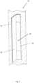
- the profile system 1 of the first embodiment comprises a collecting profile 3 and a sealing element 5, which are fastened together.
- the collecting profile 3 is a collecting profile for shower water.
- the collecting profile 3 is intended for installation in a wall or on a wall.
- the collecting profile 3 is U-shaped and has a base 7, a rear wall 9 and an upper base 11. Furthermore, an inlet slope 13 extends along the base 7 in the direction of the side facing away from the rear wall 9, integral with the U-profile. The inlet slope has a gradient towards the base 7 of the collecting profile 3. The base 7 thus forms a drainage channel. Between the floating edge of the upper base 11 and the inlet slope 13 there is a lateral opening 14 or a gap through which water can flow from a shower base over the inlet slope 13 to the base 7 of the collecting profile 3.
- the collecting profile 3 also has three drainage channels 17 in the area of the inlet slope 13, which open from the outside above the film 5 into the outlet opening 15.
- the drainage channels which extend through the extension-like inlet slope, serve as secondary drainage if water gets into the area between the inlet slope 13 and a covering, such as tiles (see also Fig. 4 ).
- the cuttable collective profile 3 can also have at least one profile end piece (not shown) that can be detachably connected to an open end of the collective profile 3.
- the collective profile 3 can have two open ends, each of which is sealed liquid-tight by means of a profile end piece.
- the profile end pieces or end caps are preferably inserted after the collective profile 3 has been cut to the installation length.
- the sealing element 5 is flat and flexible and is designed as a film or the like.
- the film has a fastening area 19. This area serves to fasten the film to the collecting profile 3.
- the film can be glued or otherwise fastened to the collecting profile 3 in the fastening area 19.
- the collecting profile 3 can have an area that contains a fastening means, such as an adhesive, whereby the collecting profile 3 is glued to the sealant 5 at the factory.
- the fastening area 19, i.e. the area of the film that is glued to the collecting profile 3, extends over the base 7 and the rear wall 11 of the collecting profile 3.
- the fastening area 19 does not extend over the entire length of the collecting profile 3.
- the collecting profile 3 has a section at both ends of the base 7 and the rear wall 9 that is not connected or glued to the film, but is overlapped by the film.
- the sealing element 5 of the first embodiment overlaps the bottom 7 and the rear wall 9 of the collecting profile 3 in the longitudinal and transverse direction thereof. This is particularly evident from the Figures 1 and 2 out.
- Fig. 2 shows the profile system, which consists of the collecting profile 3 and the sealing element 5, wherein the collecting profile is shown in a top view through the top floor 11 with the outlet opening 15 and the inlet slope 13.
- the sealing element 5 is divided into the fastening area 19 and an overlap area 21.
- the fastening area does not extend over the entire length of the collecting profile 3.
- the overlap area 21 of the film is movable and loose when not installed. Due to the extension of the fastening area 19 lengthwise less than the collecting profile length, not the entire area of the movable overlap area 21 overlaps the collecting profile 3.
- the overlap area 21 is shaped in such a way that at least part of the overlap area 21 overlaps over one side of the collecting profile 3 when the overlap area 21 rests against the rear wall 9.
- the total length of the sealing element 5 is greater than the total length of the collecting profile 3, which is why there is an overlap.
- the total width of the sealing element 5 is greater than the width of the collecting profile 3.
- the overlapping area 21 can be folded away, which allows the collecting profile 3 to be cut to a specific length (the vertical dashed lines in Fig. 2 are examples of cutting markings).
- the collecting profile 3 can be shortened at both ends so that the collecting profile 3 can be cut to a precise length for use in a shower.
- the film can also be cut accordingly.
- Fig. 3 shows the first embodiment of the profile system, in which the collecting profile 3 is arranged on a wall surface 23.
- the rear wall 11 of the collecting profile 3 is located parallel to the wall surface on the wall 23.
- the overlap area 21 is applied or sealed to the wall surface via an existing sealing film 25.
- the base 7 of the collecting profile 3 is located parallel to a base surface 27. The corresponding part of the overlap area 21 is placed on the base surface 27.
- the collecting profile 3 can be positioned vertically flexibly in this arrangement. For example, it is possible to adjust the height of the collecting profile 3 when the profile system 1 is already in the installation position. This has the advantage that the profile system 1 with its inlet slope 13 can be easily adjusted to the existing floor covering level.
- the specific arrangement of the collecting profile 3 in the vertical can be achieved by vertically moving the overlapping area 21.
- the film can be moved in an adhesive located on the floor! of the wall for attachment to a floor covering/wall covering in order to achieve alignment of the profile system.
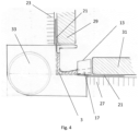
- Fig. 4 now shows the first embodiment of the profile system 1 in the installation position or in the assembled state.
- the collecting profile 3 of the first embodiment is in a wall installation position, ie the U-shaped part of the collecting profile 3 is located substantially beneath a wall covering 29.
- the floor 7 runs parallel to the floor surface, the rear wall 9 parallel to the wall surface 23 and the top floor 11 parallel to a side surface of the wall covering 29.
- the wall covering 29 is attached to the wall surface 23 on the overlapping area 21 in the form of tiles.
- the overlapping area is thus at least partially secured by the tile adhesive.
- the upper surface of the top floor 11 borders on the side surface of the wall covering 29.
- the top floor has a width such that it is approximately flush with the wall covering surface 29.
- the inlet slope 13 extends from the floor 7 to a floor covering 31. This allows water that is on the floor covering 31 to flow into the collection profile 3 via the slope of the inlet slope 13.
- the floor covering 31 can have a slope in the direction of the inlet slope 13 to ensure better drainage of the water. Water that collects between the inlet slope 13 and the floor covering 31 due to a leak or a material defect is drained to the siphon 33 via the drainage channels 17.
- the floor covering 31 is attached to the floor surface 27 above the overlap area 21 in the form of tiles.
- the overlapping area 21 is at least partially enclosed between the floor 31 or wall covering 29 and the floor 27 or wall surface 23 and thus fixed.
- the fixation is achieved by partially bonding the overlapping area 21 with tile adhesive and by pressing the overlapping area 21 against the respective wall or floor surface by the weight of the covering.
- a siphon 33 is shown that is connected to the profile system.
- the siphon 33 can be firmly connected to the profile system at the factory with foil in between.
- the siphon 33 can also be loosely connected to the profile system.
- the outlet opening 15 in the collecting profile 3 is used to drain or flow water into a drain pipe of the siphon 33.
- the foil encloses the outlet opening 15 all around, as it is firmly glued, so that there is a continuous foil seal behind/under/next to the collecting profile 3.
- Figure 5 shows a second embodiment of the profile system according to the invention in a non-installed state
- Figure 6 the second embodiment, which is not covered by the scope of protection of the patent claims, of the profile system in the installed position or in the installed state.
- the profile system 35 of the second embodiment comprises a decorative strip 41 or a gradient wedge and a sealing element 37, which are fastened to one another.
- the sealing element 37 is flat and flexible, designed as a film or the like.
- the film has a fastening area 39. This area is used to fasten the film to the decorative strip 41.
- the film is glued or otherwise fastened to the decorative strip 41 in the fastening area 39.
- the decorative strip 41 can have an area that contains a fastening means, such as adhesive, whereby the decorative strip 41 is glued to the sealing element 37.
- the fastening area 39 i.e. the area of the film that is glued to the decorative strip 41, extends at least partially over a side surface of the decorative strip 41.
- the fastening area 39 does not extend over the entire length of the decorative strip 41.
- the decorative strip 41 therefore has a section at each end that is not connected or glued to the film.
- the sealing element 37 of the second embodiment overlaps the decorative strip 41 in the longitudinal and transverse directions.
- Fig. 5 shows the profile system 35 consisting of decorative strip 41 and the sealing element 37, with the decorative strip 41 shown in a top view.
- the sealing element 37 is divided into the fastening area 39 and an overlap area 43.
- the fastening area 39 does not extend over the entire length of the decorative strip 41.
- the overlap area 43 of the film is movable when not installed. Due to the length of the fastening area 39 being less than the length of the decorative strip, the entire area of the movable overlap area 43 does not overlap the decorative strip 41.
- the overlap area 43 is shaped in such a way that at least part of the overlap area 43 overlaps one side of the decorative strip 41 when the overlap area 43 rests against the side wall of the decorative strip 41.
- the total length of the sealing element 37 is greater than the total length of the decorative strip 41, which is why there is an overlap.
- the overlap area 43 can be folded away, which allows the trim strip 41 to be cut to a specific length (the horizontal dashed lines in Fig. 5 are examples of cutting markings).
- the decorative strip 41 can be shortened at both ends so that the decorative strip 41 can be cut to a precise length for use in a shower.
- the film can also be cut accordingly.
- Fig. 6 shows an installed state of the second embodiment of the profile system 35.
- the decorative strip 41 is installed in a shower with a sloped floor.
- the floor covering 49 has a slope. This creates a height offset compared to the floor covering 51 next to the shower area.
- the floor covering 49, 51 can be provided in the form of tiles.
- the slope in the floor 45 creates a height difference compared to the floor 47 within the shower area. As the slope in the floor 45 continues, the height difference compared to the floor 47 increases.
- the floor 45 is the floor in the shower area, whereas the floor 47 is the floor next to the shower.
- the decorative strip 41 has a wedge-shaped form that essentially corresponds to the vertical surface of the height offset. When installed, the decorative strip 41 is arranged parallel to the vertical surface.
- the overlap area 43 is located between the respective floor covering 49, 51 and the respective floor 45, 47. Before the floor covering 49, 51 is attached to the floor 45, 47, the height of the decorative strip 41 can be varied by gluing the overlap area 43 to different heights.
- the Figures 7 and 8 show a third embodiment of the profile system according to the invention in a non-installed state, whereas the Figures 9 and 10 show the third embodiment of the profile system in a partially installed state.
- the Figures 11 to 13 show the third embodiment of the profile system in the installed state.
- the profile system 57 of the third embodiment comprises an L-profile 55 and a sealing element 53, which are fastened together.
- the L-profile 55 has a base 61 and a leg 59, which have an L-shape in profile.
- the width of the leg 59 can differ from the width of the base 61.
- the sealing element 53 is flat and flexible and is designed as a film or the like.
- the film has a fastening area 65. This area serves to fasten the film to the L-profile 55.
- the film is glued or otherwise fastened to the L-profile 55 in the fastening area 65.
- the L-profile 55 can have an area that contains a fastening means, such as adhesive, whereby the L-profile 55 is glued to the sealing element 53.
- the fastening area 65 ie the area of the film that is glued to the L-profile 55, extends at least partially over the base 61 of the L-profile 55 (see horizontal dashed lines in Fig. 7 ).
- the fastening area 65 does not extend over the entire length of the L-profile 55.
- the L-profile 55 has a section at each end that is not connected or glued to the film (see Figures 7 and 8 ).
- the sealing element 53 of the third embodiment overlaps the bottom 61 of the L-profile 55 in the longitudinal and transverse directions.
- Fig. 9 shows the profile system 57 consisting of the L-profile 55 and the sealing element 53, whereby the L-profile 55 is shown in a top view.
- the sealing element 53 is divided into the fastening area 65 and an overlap area 63.
- the fastening area 65 does not extend over the entire length of the L-profile 55 (see also Fig. 8 ).
- the overlapping area 63 of the film is movable when not installed. Due to the extension of the fastening area 65 lengthwise less than the L-profile length, not the entire area of the movable overlapping area 63 overlaps the L-profile 55.
- the overlapping area 63 is shaped in such a way that at least a part of the overlap region 63 overlaps over one side of the L-profile 55 when the overlap region 63 rests against the bottom of the L-profile 55.
- the total length of the sealing element 53 is greater than the total length and width of the bottom of the L-profile 55, which is why an overlap is present.
- the overlap area 63 can be folded away, which allows the L-profile 55 to be cut to a specific length.
- the L-profile 55 can be shortened at both ends so that the L-profile 55 can be cut to a precise length for use in a shower.
- the film can also be cut accordingly.
- the profile system according to the invention is arranged on a wall or on a floor 67.
- the bottom of the L-profile 55 is located on the wall or on the floor 67.
- the loose overlap area 63 of the sealing element 53 is sealed above or below an existing sealing film or seal 69.
- the L-profile 55 is in the Fig. 9 shown arrangement can be positioned flexibly vertically and horizontally. For example, it is possible to adjust the L-profile 55 vertically when the profile system is already in the installation position. This has the advantage that the profile system can be adjusted in height with ease.
- the specific arrangement of the L-profile 55 vertically can be achieved by vertically moving the overlap area 63.
- the film can be moved in an adhesive that is on the floor! of the wall for attachment to a floor covering/wall covering in order to achieve an alignment of the profile system of the third embodiment.
- the overlap area 63 is now sealed parallel to the wall or floor. This can be done by gluing.
- the L-profile 55 can still be moved in the adhesive bed in this state.
- the aforementioned structure of the profile system from the L-profile 55, to which the sealing element 53 is attached, thus enables the L-profile 55 to be easily aligned during assembly.
- the L-profile 55 can be designed as a support profile.
- An additional clamping profile 71 is attached to the L-profile 55.
- the clamping profile 71 is depth-adjustable depending on how far it is attached over the leg of the L-profile 55.
- the clamping profile 71 also has a tab that presses against an object received in the clamping profile 71 and thereby holds it in place.
- a clamping profile arranged in this way enables glass, for example, to be held between the floor or wall covering 73.
- the leg of the L-profile 55 can extend through a covering joint (e.g. a joint between two tiles 73).
- the clamping profile 71 then sits on the covering surface.
- the clamping profile 71 is also depth-adjustable and can therefore be adjusted in depth depending on the covering thickness.
- the clamping profile 71 differs in that it further comprises a plastic profile insert 75 for protecting glass 77 clamped in the clamping profile 71.
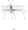
- Fig. 13 shows a further application based on the embodiment of a profile system, which is not covered by the scope of protection of the patent claims, with an L-profile 55.
- the L-profile 55 is arranged on a wall or floor surface 67 in such a way that it seals a joint in the floor (e.g. an expansion joint) or in a wall. This is done by the film of the profile system being completely attached over the joint.
- a height-adjustable splash bar profile 81 is arranged on the leg of the L-profile 55.
- Fig. 14 shows a further embodiment of a profile system, which is not covered by the scope of protection of the patent claims.
- the profile system consists of a U-profile 83 and a sealing element 85 attached to it.
- the sealing element 85 can be a film that has a fastening area that is glued to the bottom of the U-profile 83 and that has an overlap area that is arranged between a wall or floor 67 and a wall or floor covering 73.
- the film sealing is achieved by applying an existing sealing film 87 over the film 83 of the profile system.
- the U-profile 83 serves to hold an object 79 such as glass. This arrangement of the profile system also enables the sealing of a wall or floor joint 89.
- Fig. 15 shows a further embodiment of a profile system, which is not covered by the scope of protection of the patent claims.
- the profile system consists of a magnetic strip 91 and a sealing element 85 attached to it.
- the magnetic strip 91 is located between the floor covering 73 when installed.
- a magnetic profile 93 can be connected to the magnetic strip 91, which is attached to a glass 79 that functions as a shower door.
- Fig. 16 a perspective view of an application of the profile system with the embodiment as L-profile 55 in the installation position.
- the profile system consists of the L-profile 55 and a sealing element 63 attached to it. This system is attached to a wall, as described above, among other things.
- the L-profile 55 is used in conjunction with a clamping profile to accommodate a fixed glass part 103, which in turn is connected to a glass door 95 via a hinge 97.
- a screw-on cuboid 99 is located on the L-profile 55.
- a rubber intermediate layer is attached between the cuboid and the L-profile 55.
- the fixed cuboid 99 prevents the fixed glass part 103 from tipping forward out of the profile.
Landscapes
- Engineering & Computer Science (AREA)
- Architecture (AREA)
- Health & Medical Sciences (AREA)
- Public Health (AREA)
- Structural Engineering (AREA)
- Civil Engineering (AREA)
- Electromagnetism (AREA)
- Physics & Mathematics (AREA)
- General Health & Medical Sciences (AREA)
- Epidemiology (AREA)
- Water Supply & Treatment (AREA)
- Hydrology & Water Resources (AREA)
- Life Sciences & Earth Sciences (AREA)
- Mechanical Engineering (AREA)
- Residential Or Office Buildings (AREA)
- Building Environments (AREA)
- Finishing Walls (AREA)
Description
- Die Erfindung betrifft ein Profilsystem gemäß dem Oberbegriff von Anspruch 1.
- Im Allgemeinen sind Profilsysteme für sanitäre Anlagen in unterschiedlichen Ausführungen bekannt und können für verschiedene Aufgaben ausgestaltet sein. So sind zum Beispiel Profilsysteme für die Anwendung als Duschrinnenanordnung bekannt. Weiterhin sind Profilsysteme für die eingespannte Lagerung von Scheiben, wie eine Duschwand, im Bereich von Nasszellen bekannt. Darüber hinaus sind Profile zur Aufnahme von Wandverblendungspaneelen oder Zierprofile, wie ein Gefällekeil für Sanitärinstallationen bekannt. Es ist weiterhin bekannt, Profilsysteme für sanitäre Anlagen derart in eine Einbauposition zu bringen, dass eine erforderliche Dichtigkeit gegenüber Wasser gegeben ist.
- Die
DE 10 2006 007 471 B4 zeigt ein Duschbodenelement aus Hartschaumstoff für eine bodengleiche Dusche. Das Duschbodenelement weist eine zumindest oberseitig angeschäumte Folie auf, die wiederum ein Gewebe aufweisen kann. Die Folie dient als Klebevermittlungsschicht, auf die direkt ein Duschbodenbelag aufgebracht werden kann. Die Folie kann auch ein in das Duschbodenelement eingeformtes Rinnenprofil überziehen, in das ein Rinnenrahmen eingesetzt wird. - Die
EP 2 184 415 B1 zeigt eine bodengleiche Ablaufvorrichtung für den Einbau in eine Dusche oder Nasszelle. Die Vorrichtung besteht aus einer Ablaufrinne, die einen Längskragen aufweist, wobei unter dem Längskragen eine verschiebbare Zarge angeordnet ist. Im Bereich des Längskragens ist ein flexibler Dichtstreifen angeordnet, der an einer Vertikalfläche der Zarge befestigt ist. - Die
DE 10 2012 107 269 A1 zeigt einen Montagesatz zum Erzielen einer Dichtwirkung zwischen einer fest montierten Vorrichtung (z.B. eine Badewanne) und einem senkrechten Wandabschnitt. Der Montagesatz umfasst ein Anschlussband mit einem Wandabschlussstreifen, der wandseitig angeordnet wird. Weiterhin ist ein Isolationsstreifen im montierten Zustand mittels einer Klebeverbindung mit dem Wandabschlussstreifen und der Vorrichtung verbunden. - Die
DE 10 2010 016 816 A1 zeigt ein Dichtungssystem für Bodenablaufrinnen, wie sie in Duschen verwendet werden. Das Dichtungssystem weist unter anderem einen Dichtungsstreifen auf, der auf den Rand einer Rinne aufgeklebt werden kann. - Es ist somit bekannt, Profilsysteme dadurch abzudichten, indem ein Profil, wie eine Ablaufrinne, im Zuge der Montage an einem Dichtstreifen oder dergleichen angebracht wird. Die bekannten Maßnahmen zur Abdichtung von Profilsystemen sind jedoch umständlich und unflexibel in der Handhabung, da unter anderem mehrere Schritte erforderlich sind, nämlich das Anbringen eines Dichtmaterials am Montageort sowie des Montierens des Profils. Weiterhin erfordern die bekannten Systeme aufwändige bauliche Konstruktionen, um das Profil zuverlässig befestigen zu können. Schließlich ist eine Anpassung des Profils an die umgebenden Wand- und/oder Bodenbeläge in sanitären Anlagen schwierig oder gar nicht möglich.
- Vor diesem Hintergrund ist es Aufgabe der Erfindung, ein Profilsystem bereit zu stellen, das die obigen Nachteile zumindest teilweise überwindet.
- Diese Aufgabe wird durch den Gegenstand des unabhängigen Anspruchs 1 gelöst.
- Demnach umfasst das Profilsystem wenigstens ein Profilelement, das als Sammelprofil für Duschwasse vorgesehen ist. Das Profilelement kann eine vorgefertigte Rohmaterialform aufweisen, die eine grundlegende geometrische Form aufweist. Das Profilelement kann ein längliches Werkstück darstellen, das heißt die Länge des Profilelements ist um ein Vielfaches größer, als die Höhe bzw. die Tiefe.
- Das Profilelement kann in seinem Querschnitt eine U-Form, L-Form oder sonstige symmetrische oder asymmetrische Form aufweisen. Bei dem Profilelement kann es sich auch um ein Eckprofil oder kurvenförmiges Profil handeln. Das Profilsystem kann auch eine Vielzahl von Profilelementen umfassen. Diese können in einer Geraden, in einer Kurve oder auch über Eck angeordnet sein. Das Profilelement kann ein stranggepresstes oder extrudiertes Profil sein.
- Das Profilelement kann aus einem beliebigen Material hergestellt sein, das sich eignet, eine bestimmte Profilform auszubilden. Das Profilelement kann ein Metallprofil, wie Edelstahl, sein und ist bevorzugt aus Aluminium hergestellt, da Aluminium ein geringes Gewicht aufweist, sehr gut formbar ist und gleichzeitig eine ausreichende Formstabilität aufweist. Das Profilelement kann teilweise aus Aluminium oder einer Aluminiumlegierung bestehen. Es kann aber auch jedes andere Material Verwendung finden, das eine gute Formbarkeit und ein geringes Gewicht aufweist. Ebenso kann als Profilelement auch ein stranggepresstes oder extrudiertes Kunststoffprofil verwendet werden.
- Das Profilsystem umfasst neben dem wenigstens einen Profilelement auch wenigstens ein flächiges und flexibles Dichtelement zur Abdichtung zwischen Profilelement und einem an das Profilelement angrenzenden Wand- und/oder Bodenbereich. Bei dem Dichtelement kann es sich um eine Folie, ein Band, eine Membran oder sonstige flächige Ausgestaltung handeln. Das Dichtelement kann rechteckig, rund oder in einer sonstigen flächigen Form ausgestaltet sein. Bei dem Dichtelement kann es sich um eine wasserdichte Dichtfolie handeln, die aus unterschiedlichen Kunststoffen bestehen kann. Das Dichtelement kann gummiartiges Material wie beispielsweise Kautschuk oder Silikon aufweisen. Das Dichtelement kann auch aus einem Weichkunststoff bestehen. Das Dichtelement kann aus jedem Material hergestellt sein, das eine Wasserundurchlässigkeit aufweist und damit zur Dichtung geeignet ist. Das Dichtelement kann aus einem beliebigen Material hergestellt sein, das dichtend wirkt und gleichzeitig eine Zugfestigkeit aufweist, die ausreichend ist, das Gewicht eines Profilelements sicher zu tragen. Das Dichtelement kann eine Vielzahl von Dichtfolienstücke umfassen. Das Dichtelement kann eine vliesartige Beschichtung zur besseren Anhaftung von weiteren Dichtmitteln oder Klebern aufweisen. Das Dichtmittel kann eine Polyethylenfolie mit Polypropylenvlies darauf sein.
- Das Dichtelement des erfindungsgemäßen Profilsystems ist nicht nur zur Abdichtung zwischen Profilelement und einem daran angrenzenden Wand- und/oder Bodenbereich geeignet. Das Dichtelement kann auch ausgestaltet sein, jegliche unter, neben und/oder über einem Profilelement befindliche Stellen abzudichten.
- Das Dichtelement des erfindungsgemäßen Profilsystems weist weiterhin einen Befestigungsbereich auf, der in einem nicht eingebauten Zustand an dem Profilelement durch ein Befestigungsmittel befestigt ist. Der Befestigungsbereich entspricht einer Teilfläche des Dichtelements, die mit einer Oberfläche des wenigstens einen Profilelements verbunden ist. In manchen Ausführungsformen ist der Befestigungsbereich flächig mit dem Profilelement verbunden, d.h. die Teilfläche ist im Wesentlichen vollständig auf dem Profilelement befestigt. Der Befestigungsbereich kann eine zusammenhängende Fläche sein, er kann jedoch auch eine Vielzahl von Teilflächen des Dichtelements umfassen. Wenn eine Vielzahl von Dichtelementen verwendet wird, kann jedes der Vielzahl von Dichtelementen einen Befestigungsbereich aufweisen. Der Befestigungsbereich kann rechteckig, rund oder in einer sonstigen geeigneten Form ausgebildet sein. Aus der Sicht des Profilelements ist der Befestigungsbereich derjenige Bereich, der mit dem Dichtelement in flächiger Verbindung steht.
- Bei dem nicht eingebauten Zustand handelt es sich um einen Zustand, in dem sich das Profilsystem in einer werksseitigen Lieferungsanordnung befindet, d.h. das Dichtelement ist bereits an dem Profilelement befestigt, jedoch befindet es sich weder in einem abdichtenden Zustand noch an einem Montageort wie ein Wand- und/oder Bodenbereich. Das Dichtelement ist daher im nicht eingebauten Zustand nur über die Befestigungsfläche mit dem Profilelement verbunden. Der verbleibende nicht befestigte Bereich des Dichtelements ist daher lose.
- Das Dichtelement ist erfindungsgemäß an dem Profilelement befestigt. Dies erfolgt über ein Befestigungsmittel. Bei dem Befestigungsmittel kann es sich auch um eine Vielzahl von Befestigungsmitteln handeln. Das Befestigungsmittel kann ein Kleber, eine Schraube und/oder sonstige zur Anbringung der Befestigungsfläche an das Profilelement geeignete Mittel aufweisen. Das Dichtmittel kann auch angespritzt sein. Bevorzugt ist das Dichtmittel an das Profilelement geklebt. Gleichermaßen kann das Profilelement eine Klebe- bzw. Haftschicht aufweisen, an die das Dichtmittel geklebt bzw. angehaftet wird. Der Befestigungsbereich wird dann durch die Stellen definiert, wo das Dichtmittel mit dem Profilelement verbunden ist. Das Dichtmittel kann auch geklebt und zusätzlich verschraubt sein. Vorteilhafterweise ist der Befestigungsbereich so groß ausgestaltet, dass sich das Profilelement auch in senkrechter Position des Dichtmittels nicht vom Befestigungsbereich ohne Fremdeinwirkung ablösen kann. Gleichzeitig ist der Befestigungsbereich vorteilhafterweise wenigstens so groß ausgestaltet, dass ein abzudichtender Bereich, der an das Profilelement angrenzt (z.B. eine darunter liegende Fuge) sicher abgedichtet wird. Erfindungsgemäß weist das Dichtelement wenigstens einen das Profilelement überlappenden Bereich auf, wobei der Überlappungsbereich ausgestaltet ist, um das Profilelement in seiner Einbauposition zu fixieren.
- Der Überlappungsbereich steht vollständig über den Rand der zu befestigenden Fläche des Profilelements über. Vorteilhafterweise entspricht der Überlappungsbereich einer Fläche, die ausreichend groß ist, um das Profilelement zuverlässig ohne weitere Halterungseinrichtungen an einer Wand oder einem Boden befestigen zu können. Im nicht eingebauten Zustand ist der flächige Überlappungsbereich flexibel, lose bzw. beweglich.
- Vorteilhafterweise kann das Profilelement daher auf eine benötigte Länge zugeschnitten werden.
- Das erfindungsgemäße Profilsystem ermöglicht neben der zuverlässigen Befestigung eines Profilelements an bzw. in einer Wand oder auf einem Boden auch eine variable Anpassung der Höhe des Profilelements während der Montage. Zudem ist auch eine Größenanpassung (z.B. Ablängung) des Profilsystems je nach baulicher Gegebenheit sehr einfach durchzuführen. Gleichzeitig ist eine hohe Abdichtungswirkung durch die Verwendung eines Dichtmittels, wie eine Dichtfolie, sichergestellt.
- Das erfindungsgemäße Profilsystem ist in erster Linie für eine sanitäre Anlage, wie eine bodengleiche Dusche gedacht, jedoch soll es in keiner Weise auf diese Anwendung beschränkt sein.
- In manchen Ausführungsformen ist die Einbauposition des Profilelements durch den Überlappungsbereich variabel in der Vertikalen und/oder Horizontalen anpassbar. Unter Einbauposition wird diejenige Position verstanden, in der das Profilelement an einer Boden-, Wand- und/oder Deckenfläche lose angeordnet ist, d.h. in der das Profilsystem noch nicht fixiert ist. Vorteilhafterweise ist der Überlappungsbereich wenigstens so groß, dass dieser Bereich ausreicht, das Profilelement im eingebauten Zustand in einer bestimmten Position stabil zu halten.
- In manchen Ausführungsformen erstreckt sich der Überlappungsbereich an zumindest zwei gegenüberliegenden Seiten des Befestigungsbereichs in Form von zwei Teilüberlappungsbereichen, die zur Montage des Profilelements an wenigstens einer Wand-, Deckenund/oder Bodenfläche, und/oder eines jeweils damit verbundenen Belags vorgesehen sind. Die zwei Teilüberlappungsbereiche fungieren als Fixierungsvorrichtungen, d.h. wenn sich das Profilsystem in Einbauposition befindet, sind die Teilüberlappungsbereiche an einer Wand-, Decken- und/oder Bodenfläche etwas mittels Fliesen und/oder Fliesenkleber befestigt, um das am Befestigungsbereich befestigte Profilelement stabil zu halten. Entsprechend sind die Teilüberlappungsbereiche ausreichend dimensioniert, um das Gewicht des Profilelements sicher zu halten, d.h. ein Kippen oder eine Verdrehung des Profilelements ist nicht möglich.
- In manchen Ausführungsformen ist das Profilelement und/oder das Dichtelement zuschneidbar ausgeführt. Das Profilelement kann im nicht eingebauten Zustand in seiner Längsrichtung nur teilweise von dem Dichtelement bedeckt sein. Das Profilelement kann einen Endabschnitt aufweisen, an dem das Dichtelement nicht befestigt ist. Das Profilelement kann auch beide Endabschnitte ohne daran befestigtes Dichtmittel aufweisen. Das Profilelement kann entsprechend einem Kundenwunsch mittels einer Säge oder eines anderen Schneidwerkzeugs in dem Abschnittsbereich, wo sich keine angeklebte Dichtfolie befindet, individuell gekürzt werden. Das Profilelement kann auf diese Weise optimal an ein Fliesen- oder Bodenplattenformat bzw. ein Fugenraster im Bereich von sanitären Anlagen angepasst werden. Bevorzugt ist das Profilelement an seinen Längsenden nicht mit dem Dichtelement bedeckt. Vorteilhafterweise kann das Profilelement somit an beiden Enden zugeschnitten werden. Dies ermöglicht eine individuelle Anpassung der Profilelementlänge an die baulichen Gegebenheiten am Montageort.
- Das zuschneidbare Profilelement kann auch wenigstens ein Profilendstück aufweisen, das mit einem offenen Ende des Profilelements lösbar verbindbar ist. Das Profilelement kann zwei offene Ende aufweisen, die jeweils mittels eines Profilendstücks flüssigkeitsdicht abgesperrt werden. Die Profilendstücke bzw. Endkappen werden bevorzugt nach dem Zuschneiden des Profilelements auf die Einbaulänge eingesetzt.
- Das Profilelement ist als Sammelprofil für Duschwasser zum Einbau in oder Anbau an eine Wand vorgesehen. Das erfindungsgemäße Sammelprofil ist nicht auf diese Anwendung beschränkt. Das Sammelprofil kann auch eine Ablaufrinne oder einen Rinnenkörper umfassen. Das Sammelprofil kann ganz oder teilweise in eine Wand integriert werden. Das Sammelprofil kann auch in den Boden vor einer Wand integriert werden. Das Profilsystem bestehend aus Sammelprofil und Dichtelement kann überall in einer Duschzelle angeordnet werden, wo sich Wasser ansammelt, das zu einem Abfluss geleitet werden soll.
- In manchen Ausführungsformen weist das Profilelement wenigstens eine Einlassöffnung zum Einlassen von Duschwasser in das Sammelprofil auf. Die Einlassöffnung kann seitlich angeordnet sein. Die Einlassöffnung kann sich vorzugsweise über die gesamte Länge des Sammelprofils erstrecken. Es können auch mehrere Einlassöffnungen vorhanden sein. Die Einlassöffnung kann mit einer Abdeckung vorgesehen sein, die ausgestaltet ist, um weiterhin Wasser hindurchzulassen, jedoch verhindert, dass Kleinteile oder Körperteile in das Sammelprofil gelangen können.
- In manchen Ausführungsformen weist das Profilelement wenigstens eine Auslassöffnung zum Auslassen von Duschwasser in einen Siphon auf. Die Auslassöffnung entspricht einem Abfluss. Die Auslassöffnung kann in der Sammelöffnung derart angeordnet sein, dass diese einfach zur Reinigung mittels eines Duschstrahls zu erreichen ist. Bevorzugt ist die Auslassöffnung im Boden, d.h. in einer unteren Fläche des Sammelprofils angeordnet. Die Auslassöffnung kann so angeordnet sein, dass zur Auslassöffnung hin geneigte Flächen daran angeordnet sind, um den Wasserablauf zu verbessern. Es können auch mehrere Auslassöffnungen vorhanden sein.
- In manchen Ausführungsformen weist das Profilelement wenigstens eine Einlassöffnung und eine Auslassöffnung auf. Vorzugsweise ist die Einlassöffnung in Einbauposition auf einem höheren Niveau als die Auslassöffnung angeordnet, um den Wasserablauf zu verbessern
- In manchen Ausführungsformen ist das Sammelprofil U-förmig mit einem Boden, einer Rückwand und einem Oberboden vorgesehen. Das Sammelprofil kann auch eine andere Querschnittsprofilausgestaltung (z.B. ein C-Profil oder L-Profil) aufweisen. Das Sammelprofil kann an seinen Längsenden zudem jeweils ein Sammelprofilendstück zur seitlichen Abdichtung aufweisen. Das Sammelprofil kann somit abgesehen von der Einlassöffnung und der Auslassöffnung geschlossen ausgebildet sein.
- In manchen Ausführungsformen ist die Einlassöffnung auf der von der Rückwand abgewandten Seite vorgesehen. Demnach kann die Öffnung gegenüber der Rückwand liegen, d.h. es kann sich um eine seitliche Einlassöffnung handeln. Die Öffnung kann sich über die gesamte Höhe des U-förmigen Profils erstrecken. Die Öffnung kann durch einen weiteren Schenkel, der sich ausgehend von dem Ende des Bodens gegenüber der Rückwand senkrecht über eine Höhe erstreckt, die kleiner ist als die gesamte Höhe des U-förmigen Profils, verkleinert sein. Dieser weitere Schenkel kann sich bis auf eine Höhe erstrecken, die in der Einbauposition des Profilsystems einem Bodenbelagsniveau entspricht, so dass der Wassereinlauf in die Einlassöffnung sichergestellt ist.
- In manchen Ausführungsformen ist die Auslassöffnung im Boden ausgebildet. Die Auslassöffnung kann als eine runde, eine eckige oder sonstige geeignete Form aufweisende Öffnung ausgebildet sein, die ein Ableiten des Wassers, das sich in dem Sammelprofil befindet, in einen Siphon oder dergleichen ermöglicht.
- In manchen Ausführungsformen ist das Sammelprofil U-förmig mit einem Boden, einer Rückwand und einem Oberboden vorgesehen, die Öffnung auf der von der Rückwand abgewandten Seite vorgesehen und die Auslassöffnung im Boden ausgebildet.
- In manchen Ausführungsformen erstreckt sich bei dem erfindungsgemäßen Profilsystem entlang des Bodens in Richtung der von der Rückwand abgewandten Seite eine nach innen geneigte Einlaufschräge. Die Einlaufschräge und das Sammelprofil können einstückig ausgeformt sein. Die Einlaufschräge und das Sammelprofil können lösbar miteinander verbunden sein. Die Einlaufschräge kann aus dem gleichen Material wie das Sammelprofil hergestellt sein. Die Einlaufschräge kann ein Gefälle aufweisen, das in Richtung der Auslassöffnung zeigt. An seinem höchsten Punkt darf die Einlaufschräge im eingebauten Zustand maximal das Oberflächenniveau des Duschbodens aufweisen. Die Einlaufschräge kann auch ohne eine Steigung, sprich horizontal im eingebauten Zustand, ausgebildet sein.
- In manchen Ausführungsformen weist die Einlaufschräge wenigstens einen Drainagekanal auf. Der wenigstens eine Drainagekanal erstreckt sich mit einem Gefälle hin zur Auslassöffnung durch die Einlaufschräge. Der Drainagekanal ist ausgebildet, um Wasser zum Ablauf zu leiten, das sich im eingebauten Zustand zwischen der vorderen Fläche der Einlaufschräge und dem Bodenbelag angesammelt. Bevorzugt weist die Einlaufschräge eine Vielzahl von Drainagekanälen auf.
- In manchen Ausführungsformen ist der Befestigungsbereich mit der Rückwand und dem Boden des Sammelprofils flächig verbunden, wobei der Befestigungsbereich die Rückwand und den Boden teilweise bedeckt. Dadurch ist ein Teilbereich des Dichtelements, das sich von dem Befestigungsbereich aus erstreckt, nicht mit dem Boden und der Rückwand des Profilelements verbunden. Bevorzugt ist der Befestigungsbereich derart angeordnet, dass das Profilelement Endabschnitte aufweist, mit denen das Dichtelement nicht verbunden ist. An diesen Endabschnitten kann das Profilelement vorteilhafterweise zugeschnitten sein.
- In manchen Ausführungsformen ist die Einlassöffnung des Sammelprofils konfiguriert, in der Einbauposition einen Spalt als Wasserablauf zwischen einem Wandbelag, insbesondere von Fliesen, und einem Bodenbelag, insbesondere von Fliesen, zu bilden. Bevorzugt weist der Spalt eine Höhe auf, die ausreichend groß ist, dass das Sammelprofil mit der Duschkopfbrause in montiertem Zustand gereinigt werden kann. Bevorzugt ist der Spalt derart ausgestaltet, dass keine Kleinteile oder Körperteile wie Zehen eindringen können.
- Ein Siphon kann mit dem erfindungsgemäßen Profilsystem ausgestaltet sein. Der Siphon kann ein Ablaufsystem sein, durch das Abwasser oder Duschwasser hindurchtreten kann. Der Siphon kann werkseitig mit dem Profil verbunden sein. Bevorzugt ist dabei eine Folie fest zwischen Siphon und Profil verbunden. Bei dem Siphon handelt es sich bevorzugt um einen strömungsoptimierten, selbstreinigenden Siphon. Vorteilhafterweise kann bei der Verwendung eines selbstreinigenden Siphons die Einlassöffnung des Profilsystems sehr schmal ausgestaltet sein.
- Ein Duschelement kann mit dem erfindungsgemäßen Profilsystem ausgestaltet sein.
- Sämtliche Ausführungsformen des Profilelements können durch die Befestigung mit dem Dichtelement bei gleichzeitig aufweisenden losen Überlappungsbereich einen angrenzenden Wand-, Decken oder Bodenbereich sehr gut abdichten. Insbesondere können auch Fugenbereiche hinter dem Dichtelement abgedichtet sein.
- Weitere Ausgestaltungen der Erfindung ergeben sich im Rahmen der nachfolgenden Ansprüche sowie der nachfolgenden Figurenbeschreibung und Zeichnungen.
- Ausführungsbeispiele der Erfindung sind im Folgenden unter Bezugnahme auf die beigefügten, schematischen Zeichnungen näher erläutert. Dabei zeigt:
- Fig. 1
- eine perspektivische Darstellung eines Profilsystems gemäß einer ersten Ausführungsform in einer Ansicht schräg von vorne;
- Fig. 2
- eine Draufsicht des Profilsystems gemäß der ersten Ausführungsform von oben,
- Fig. 3
- einen Querschnitt des Profilsystems gemäß der ersten Ausführungsform an einer Wandfläche angeordnet;
- Fig. 4
- einen Querschnitt des Profilsystems gemäß der ersten Ausführungsform in Einbauposition;
- Fig. 5
- eine Draufsicht des Profilsystems gemäß einer zweiten Ausführungsform;
- Fig. 6
- eine perspektivische Querschnittsansicht des Profilsystems gemäß der zweiten Ausführungsform,
- Fig. 7
- eine perspektivische Darstellung eines Profilsystems gemäß einer dritten Ausführungsform, die nicht von dem Schutzumfang der Patentansprüche umfasst wird, in einer Ansicht von vorne;
- Fig. 8
- eine perspektivische Darstellung des Profilsystems gemäß der dritten Ausführungsform in einer Ansicht schräg von vorne;
- Fig. 9
- einen Querschnitt des Profilsystems gemäß der dritten Ausführungsform an einer Fläche angeordnet;
- Fig. 10
- einen Querschnitt des Profilsystems gemäß der dritten Ausführungsform in teilweise eingebauter Position;
- Fig. 11
- einen Querschnitt eines Profilsystems gemäß der dritten Ausführungsform in einer Anwendung;
- Fig. 12
- einen Querschnitt eines Profilsystems gemäß der dritten Ausführungsform in einer weiteren Anwendung;
- Fig. 13
- einen Querschnitt eines Profilsystems gemäß der dritten Ausführungsform in einer weiteren Anwendung;
- Fig. 14
- einen Querschnitt eines Profilsystems gemäß einer weiteren Ausführungsform, die nicht von dem Schutzumfang der Patentansprüche umfasst wird, in Einbauposition;
- Fig. 15
- einen Querschnitt eines Profilsystems gemäß einer weiteren Ausführungsform, die nicht von dem Schutzumfang der Patentansprüche umfasst wird, in Einbauposition; und
- Fig. 16
- eine perspektivische Darstellung des Profilsystems gemäß der dritten Ausführungsform, die nicht von dem Schutzumfang der Patentansprüche umfasst wird, in einer weiteren Anwendung.
- In der Folge verwendete Lagebezeichnungen, wie oben, unten, vorne, hinten, rechts und links beziehen sich aus der Sicht eines Betrachters auf ein vor ihm angeordnetes erfindungsgemäßes Profilsystem in Einbauposition.
- Der Aufbau des erfindungsgemäßen Profilsystems wird zunächst anhand der
Figuren 1 bis 4 für eine erste Ausführungsform erläutert. DieFiguren 1 und2 zeigen dabei die erste Ausführungsform des erfindungsgemäßen Profilsystems in einem nicht eingebauten Zustand, wohingegen dieFigur 3 die erste Ausführungsform in einem teilweise eingebauten Zustand undFigur 4 die erste Ausführungsform des erfindungsgemäßen Profilsystems in einer Einbauposition bzw. im einem eingebauten Zustand zeigen. - Wie in
Fig. 1 gezeigt, umfasst das Profilsystem 1 der ersten Ausführungsform ein Sammelprofil 3 und ein Dichtelement 5, die miteinander befestigt sind. Bei dem Sammelprofil 3 handelt es sich um ein Sammelprofil für Duschwasser. Das Sammelprofil 3 ist für den Einbau in eine Wand oder an eine Wand vorgesehen. - Das Sammelprofil 3 ist U-förmig ausgebildet und weist einen Boden 7, eine Rückwand 9 und einen Oberboden 11 auf. Weiterhin erstreckt sich entlang des Bodens 7 in Richtung der von der Rückwand 9 abgewandten Seite einstückig mit dem U-Profil eine Einlaufschräge 13. Die Einlaufschräge weist ein Gefälle zum Boden 7 des Sammelprofils 3 hin auf. Der Boden 7 bildet somit eine Ablaufrinne. Zwischen der schwebenden Kante des Oberbodens 11 und der Einlaufschräge 13 befindet sich eine seitliche Öffnung 14 bzw. ein Spalt, durch den Wasser von einem Duschboden über die Einlaufschräge 13 auf den Boden 7 des Sammelprofils 3 fließen kann.
- Der Boden 7 weist zudem eine Auslassöffnung 15 auf, durch die Wasser beispielsweise in einen Siphon abfließen kann. Die Auslassöffnung 15 ist schlitzförmig ausgebildet und mittig des Sammelprofils 3 angeordnet. Der Boden 7 kann ein Gefälle hin zur Auslassöffnung 15 aufweisen, um den Wasserablauf zu verbessern. Durch die Auslassöffnung 15 wird Wasser in einen Ablauf bzw. ein Siphon abgeleitet (wie in
Fig. 4 gezeigt). - Das Sammelprofil 3 weist weiterhin drei Drainagekanäle 17 im Bereich der Einlaufschräge 13 auf, die von außen oberhalb der Folie 5 in die Auslassöffnung 15 münden. Die Drainagekanäle, die sich durch die fortsatzartige Einlaufschräge erstrecken dienen als Sekundärentwässerung, falls Wasser in den Bereich zwischen der Einlaufschräge 13 und einem Belag, wie Fliesen, gelangt (siehe auch
Fig. 4 ). - Das zuschneidbare Sammelprofil 3 kann auch wenigstens ein Profilendstück (nicht gezeigt) aufweisen, das mit einem offenen Ende des Sammelprofils 3 lösbar verbindbar ist. Das Sammelprofil 3 kann zwei offene Ende aufweisen, die jeweils mittels eines Profilendstücks flüssigkeitsdicht abgesperrt werden. Die Profilendstücke bzw. Endkappen werden bevorzugt nach dem Zuschneiden des Sammelprofils 3 auf die Einbaulänge eingesetzt.
- Das Dichtelement 5 ist flächig und flexibel als eine Folie oder dergleichen ausgestaltet. Gemäß der in den
Figuren 1 und2 gezeigten Ausführungsform, weist die Folie einen Befestigungsbereich 19 auf. Dieser Bereich dient zu Befestigung der Folie mit dem Sammelprofil 3. Die Folie kann in dem Befestigungsbereich 19 an das Sammelprofil 3 geklebt oder anderweitig befestigt sein. Gleichermaßen kann das Sammelprofil 3 einen Bereich aufweisen, der ein Befestigungsmittel, wie einen Kleber enthält, wodurch das Sammelprofil 3 an das Dichtmittel 5 werkseitig geklebt ist. Der Befestigungsbereich 19, d.h. der Bereich der Folie, der mit dem Sammelprofil 3 verklebt ist, erstreckt sich über den Boden 7 und die Rückwand 11 des Sammelprofils 3. Der Befestigungsbereich 19 erstreckt sich nicht über die gesamte Länge des Sammelprofils 3. Somit weist das Sammelprofil 3 an beiden Enden des Bodens 7 und der Rückwand 9 jeweils einen Abschnitt auf, der nicht mit der Folie verbunden bzw. verklebt ist, aber von der Folie überlappt wird.. - Das Dichtelement 5 der ersten Ausführungsform überlappt den Boden 7 und die Rückwand 9 des Sammelprofils 3 in Längs- und Querrichtung dessen. Dies geht insbesondere aus den
Figuren 1 und2 hervor.Fig. 2 zeigt das Profilsystem, das aus Sammelprofil 3 und dem Dichtelement 5 besteht, wobei das Sammelprofil durch den Oberboden 11 mit der Auslassöffnung 15 und die Einlaufschräge 13 in einer Draufsicht dargestellt ist. Das Dichtelement 5 ist in den Befestigungsbereich 19 sowie in einen Überlappungsbereich 21 aufgeteilt. Der Befestigungsbereich erstreckt sich nicht über die gesamte Länge des Sammelprofils 3. Der Überlappungsbereich 21 der Folie ist im nicht eingebauten Zustand beweglich und lose. Aufgrund der Ausdehnung des Befestigungsbereichs 19 der Länge nach weniger als die Sammelprofillänge, überlappt nicht der gesamte Bereich des beweglichen Überlappungsbereichs 21 das Sammelprofil 3. Der Überlappungsbereich 21 ist derart ausgeformt, dass jedenfalls ein Teil des Überlappungsbereichs 21 über eine Seite des Sammelprofils 3 überlappt, wenn der Überlappungsbereich 21 an der Rückwand 9 anliegt. Mit anderen Worten ausgedrückt, ist die Gesamtlänge des Dichtelements 5 größer als die Gesamtlänge des Sammelprofils 3, weshalb ein Überlapp vorhanden ist. Wie inFig. 1 gezeigt, ist zudem die Gesamtbreite des Dichtelements 5 größer als die Breite des Sammelprofils 3. - Der Überlappungsbereich 21 kann weggeklappt sein, wodurch ein Zuschneiden des Sammelprofils 3 auf eine bestimmte Länge ermöglicht ist (die senkrechten gestrichelten Linien in
Fig. 2 stehen beispielhaft für Zuschnittmarkierungen). Das Sammelprofil 3 kann an beiden Enden gekürzt sein, so dass eine passgenaue Länge des Sammelprofils 3 für den Einsatz in einer Dusche erfolgen kann. Entsprechend kann auch die Folie zugeschnitten sein. -
Fig. 3 zeigt die erste Ausführungsform des Profilsystems, bei dem das Sammelprofil 3 an einer Wandfläche 23 angeordnet ist. Dabei befindet sich die Rückwand 11 des Sammelprofils 3 parallel zur Wandoberfläche an der Wand 23. Der Überlappungsbereich 21 ist über eine bestehende Abdichtungsfolie 25 an die Wandoberfläche angelegt bzw. angedichtet. Der Boden 7 des Sammelprofils 3 befindet sich parallel zu einer Bodenfläche 27. Der entsprechende Teil des Überlappungsbereichs 21 ist auf die Bodenfläche 27 gelegt. - Das Sammelprofil 3 ist in dieser Anordnung vertikal flexibel positionierbar. So ist es zum Beispiel möglich, das Sammelprofil 3 in der Höhe anzupassen, wenn sich das Profilsystem 1 bereits in der Einbauposition befindet. Dies hat den Vorteil, dass das Profilsystem 1 mit seiner Einlaufschräge 13 in einfacher Handhabung an das bestehende Bodenbelagsniveau angepasst werden kann. Die konkrete Anordnung des Sammelprofils 3 in der Vertikalen kann durch vertikales Verschieben des Überlappungsbereichs 21 bewirkt werden. Insbesondere kann die Folie in einem Kleber, der sich auf dem Boden! der Wand zur Befestigung mit einem Bodenbelag/ Wandbelag befindet, verschoben werden, um damit eine Ausrichtung des Profilsystems zu erreichen.
-
Fig. 4 zeigt nun die erste Ausführungsform des Profilsystems 1 in Einbauposition bzw. im montierten Zustand. Das Sammelprofil 3 der ersten Ausführungsform befindet sich in einer Wandeinbauposition, d.h. der U-förmige Teil des Sammelprofils 3 befindet sich im Wesentlichen unterhalb eines Wandbelags 29. Der Boden 7 verläuft parallel zur Bodenfläche, die Rückwand 9 parallel zur Wandfläche 23 und der Oberboden 11 parallel zu einer Seitenfläche des Wandbelags 29. Der Wandbelag 29 ist an der Wandoberfläche 23 auf dem Überlappungsbereich 21 in Form von Fliesen angebracht. Der Überlappungsbereich ist somit zumindest teilweise durch den Fliesenkleber befestigt. Die obere Fläche des Oberbodens 11 grenzt an die Seitenfläche des Wandbelags 29 an. Weiterhin weist der Oberboden eine Breite auf, so dass dieser in etwa bündig mit der Wandbelagsoberfläche 29 ist. Vorteilhafterweise wird durch den flächigen Überlappungsbereich 21 und den Befestigungsbereich 19 der werkseitig an das Profilelement 3 angebracht ist, eine Abdichtung und zuverlässige Befestigung des Profilelements 3 zugleich erreicht. - Vom Boden 7 erstreckt sich die Einlaufschräge 13 hin zu einem Bodenbelag 31. Somit kann Wasser, dass sich auf dem Bodenbelag 31 befindet über das Gefälle der Einlaufschräge 13 in das Sammelprofil 3 hineinfließen. Der Bodenbelag 31 kann ein Gefälle in Richtung der Einlaufschräge 13 aufweisen, damit ein besserer Ablauf des Wassers gewährleistet ist. Wasser, dass sich aufgrund einer Undichtigkeit oder eines Materialfehlers zwischen Einlaufschräge 13 und Bodenbelag 31 ansammelt, wird über die Drainagekanäle 17 zum Siphon 33 abgeleitet.
- Der Bodenbelag 31 ist an der Bodenfläche 27 über dem Überlappungsbereich 21 in Form von Fliesen angebracht. In dem eingebauten Zustand, wie in
Fig. 4 gezeigt, ist der Überlappungsbereich 21 jedenfalls teilweise fest zwischen dem Boden- 31 bzw. Wandbelag 29 und der Boden- 27 bzw. Wandoberfläche 23 eingeschlossen und damit fixiert. Die Fixierung entsteht durch die teilweise Verklebung des Überlappungsbereichs 21 mit Fliesenkleber sowie durch Anpressen des Überlappungsbereichs 21 durch das Gewicht des Belags an die jeweilige Wand- bzw. Bodenoberfläche. - Weiterhin ist in
Fig. 4 ein Siphon 33 dargestellt, der mit dem Profilsystem verbunden ist. Der Siphon 33 kann werkseitig mit Folie dazwischen fest mit dem Profilsystem verbunden sein. Der Siphon 33 kann aber auch lose an das Profilsystem anschließen. Die Auslassöffnung 15 im Sammelprofil 3 dient dazu, dass Wasser in ein Abflussrohr des Siphons 33 abgeleitet wird bzw. fließt. Die Folie umschließt die Auslassöffnung 15 rundum, da diese fest verklebt ist, so dass eine durchgehende Folienabdichtung hinter/unter/neben dem Sammelprofil 3 besteht. -
Figur 5 zeigt eine zweite Ausführungsform des erfindungsgemäßen Profilsystems in nicht eingebautem Zustand, wohingegenFigur 6 die zweite Ausführungsform, die nicht von dem Schutzumfang der Patentansprüche umfasst wird, des Profilsystems in Einbauposition bzw. im eingebauten Zustand zeigt. - Wie in
Fig. 5 gezeigt, umfasst das Profilsystem 35 der zweiten Ausführungsform eine Zierleiste 41 bzw. ein Gefällekeil und ein Dichtelement 37, die miteinander befestigt sind. - Das Dichtelement 37 ist flächig und flexibel als eine Folie oder dergleichen ausgestaltet. Die Folie weist einen Befestigungsbereich 39 auf. Dieser Bereich dient zu Befestigung der Folie mit der Zierleiste 41. Die Folie ist in dem Befestigungsbereich 39 an die Zierleiste 41 geklebt oder anderweitig befestigt. Gleichermaßen kann die Zierleiste 41 einen Bereich aufweisen, der ein Befestigungsmittel, wie Kleber enthält, wodurch die Zierleiste 41 an das Dichtelement 37 geklebt wird. Der Befestigungsbereich 39, d.h. der Bereich der Folie, der mit der Zierleiste 41 verklebt ist, erstreckt sich zumindest teilweise über eine Seitenfläche der Zierleiste 41. Der Befestigungsbereich 39 erstreckt sich nicht über die gesamte Länge der Zierleiste 41. Somit weist die Zierleiste 41 an beiden Enden jeweils einen Abschnitt auf, der nicht mit der Folie verbunden bzw. verklebt ist.
- Das Dichtelement 37 der zweiten Ausführungsform überlappt die Zierleiste 41 in Längsund Querrichtung.
Fig. 5 zeigt das Profilsystem 35 bestehend aus Zierleiste 41 und dem Dichtelement 37, wobei die Zierleiste 41 in einer Draufsicht dargestellt ist. Das Dichtelement 37 ist in den Befestigungsbereich 39 sowie in einen Überlappungsbereich 43 aufgeteilt. Der Befestigungsbereich 39 erstreckt sich nicht über die gesamte Länge der Zierleiste 41. Der Überlappungsbereich 43 der Folie ist im nicht eingebauten Zustand beweglich. Aufgrund der Ausdehnung des Befestigungsbereichs 39 der Länge nach weniger als die Zierleistenlänge, überlappt nicht der gesamte Bereich des beweglichen Überlappungsbereichs 43 die Zierleiste 41. Der Überlappungsbereich 43 ist derart ausgeformt, dass jedenfalls ein Teil des Überlappungsbereichs 43 über eine Seite der Zierleiste 41 überlappt, wenn der Überlappungsbereich 43 an der Seitenwand der Zierleiste 41 anliegt. Mit anderen Worten ausgedrückt, ist die Gesamtlänge des Dichtelements 37 größer als die Gesamtlänge der Zierleiste 41, weshalb ein Überlapp vorhanden ist. - Der Überlappungsbereich 43 kann weggeklappt sein, wodurch ein Zuschneiden der Zierleiste 41 auf eine bestimmte Länge ermöglicht wird (die waagrechten gestrichelten Linien in
Fig. 5 stehen beispielhaft für Zuschnittmarkierungen). Die Zierleiste 41 kann an beiden Enden gekürzt sein, so dass eine passgenaue Länge der Zierleiste 41 für den Einsatz in einer Dusche erfolgen kann. Entsprechend kann auch die Folie zugeschnitten sein. -
Fig. 6 zeigt einen eingebauten Zustand der zweiten Ausführungsform des Profilsystems 35. Die Zierleiste 41 ist in einer Dusche mit Bodengefälle eingebaut. Dabei weist der Bodenbelag 49 ein Gefälle auf. Dadurch entsteht ein Höhenversatz gegenüber dem Bodenbelag 51 neben dem Duschbereich. Der Bodenbelag 49, 51 kann in Form von Fliesen vorgesehen sein. Gleichermaßen entsteht durch das Gefälle im Boden 45 ein Höhenunterschied gegenüber dem Boden 47 innerhalb des Duschbereichs. Mit Fortlauf des Gefälles im Boden 45 nimmt der Höhenunterschied gegenüber dem Boden 47 zu. Bei dem Boden 45 handelt es sich um den Boden im Duschbereich, wohingegen es sich bei dem Boden 47 um den Boden neben der Dusche handelt. - Die Zierleiste 41 weist eine keilförmige Form auf, die im Wesentlichen der vertikalen Fläche des Höhenversatzes entspricht. Im eingebauten Zustand befindet sich die Zierleiste 41 parallel zur vertikalen Fläche angeordnet. Der Überlappungsbereich 43 befindet sich zwischen dem jeweiligen Bodenbelag 49, 51 und dem jeweiligen Boden 45, 47. Bevor der Bodenbelag 49, 51 auf dem Boden 45, 47 befestigt wird, kann die Zierleiste 41 durch unterschiedlich hohes Ankleben des Überlappungsbereichs 43 in der Höhe variiert sein.
- Die
Figuren 7 und8 zeigen eine dritte Ausführungsform des erfindungsgemäßen Profilsystems in nicht eingebautem Zustand, wohingegen dieFiguren 9 und10 die dritte Ausführungsform des Profilsystems in einem teilweise eingebauten Zustand zeigen. DieFiguren 11 bis 13 zeigen die dritte Ausführungsform des Profilsystems im eingebauten Zustand. - Wie in den
Figuren 7 und8 gezeigt, umfasst das Profilsystem 57 der dritten Ausführungsform ein L-Profil 55 und ein Dichtelement 53, die miteinander befestigt sind. - Das L-Profil 55 weist einen Boden 61 und einen Schenkel 59 auf, die im Profil eine L-Form aufweisen. Die Breite des Schenkels 59 kann sich von der Breite des Bodens 61 unterscheiden.
- Das Dichtelement 53 ist flächig und flexibel als eine Folie oder dergleichen ausgestaltet. Die Folie weist einen Befestigungsbereich 65 auf. Dieser Bereich dient zu Befestigung der Folie mit dem L-Profil 55. Die Folie ist in dem Befestigungsbereich 65 an das L-Profil 55 geklebt oder anderweitig befestigt. Gleichermaßen kann das L-Profil 55 einen Bereich aufweisen, der ein Befestigungsmittel, wie Kleber enthält, wodurch das L-Profil 55 an das Dichtelement 53 geklebt wird. Der Befestigungsbereich 65, d.h. der Bereich der Folie, der mit dem L-Profil 55 verklebt ist, erstreckt sich zumindest teilweise über den Boden 61 des L-Profils 55 (siehe waagrechte gestrichelte Linien in
Fig. 7 ). Der Befestigungsbereich 65 erstreckt sich nicht über die gesamte Länge des L-Profils 55. Somit weist das L-Profil 55 an beiden Enden jeweils einen Abschnitt auf, der nicht mit der Folie verbunden bzw. verklebt ist (sieheFiguren 7 und8 ). - Das Dichtelement 53 der dritten Ausführungsform überlappt jedenfalls den Boden 61 des L-Profils 55 in Längs- und Querrichtung.
Fig. 9 zeigt das Profilsystem 57 bestehend aus L-Profil 55 und dem Dichtelement 53, wobei das L-Profil 55 in einer Draufsicht dargestellt ist. Das Dichtelement 53 ist in den Befestigungsbereich 65 sowie in einen Überlappungsbereich 63 aufgeteilt. Der Befestigungsbereich 65 erstreckt sich nicht über die gesamte Länge des L-Profils 55 (siehe auchFig. 8 ). Der Überlappungsbereich 63 der Folie ist im nicht eingebauten Zustand beweglich. Aufgrund der Ausdehnung des Befestigungsbereichs 65 der Länge nach weniger als die L-Profillänge, überlappt nicht der gesamte Bereich des beweglichen Überlappungsbereichs 63 das L-Profil 55. Der Überlappungsbereich 63 ist derart ausgeformt, dass jedenfalls ein Teil des Überlappungsbereichs 63 über eine Seite des L-Profils 55 überlappt, wenn der Überlappungsbereich 63 am Boden des L-Profils 55 anliegt. Mit anderen Worten ausgedrückt, ist die Gesamtlänge des Dichtelements 53 größer als die Gesamtlänge und -breite des Bodens des L-Profils 55, weshalb ein Überlapp vorhanden ist. - Der Überlappungsbereich 63 kann weggeklappt werden, wodurch ein Zuschneiden des L-Profils 55 auf eine bestimmte Länge ermöglicht wird. Das L-Profil 55 kann an beiden Enden gekürzt werden, so dass eine passgenaue Länge des L-Profils 55 für den Einsatz in einer Dusche erfolgen kann. Entsprechend kann auch die Folie zugeschnitten werden.
- Im teilweise eingebauten Zustand, wie in den
Figuren 9 und10 gezeigt, ist das erfindungsgemäße Profilsystem an einer Wand oder auf einem Boden 67 angeordnet. Insbesondere befindet sich der Boden des L-Profils 55 an der Wand oder auf dem Boden 67. Der lose Überlappungsbereich 63 des Dichtelements 53 wird über oder unter eine bestehende Abdichtungsfolie oder Abdichtung 69 angedichtet. - Das L-Profil 55 ist in der in
Fig. 9 gezeigten Anordnung vertikal und horizontal flexibel positionierbar. So ist es zum Beispiel möglich, das L-Profil 55 in der Vertikalen anzupassen, wenn sich das Profilsystem bereits in der Einbauposition befindet. Dies hat den Vorteil, dass das Profilsystem in einfacher Handhabung höhenmäßig angepasst werden kann. Die konkrete Anordnung des L-Profils 55 in der Vertikalen kann durch vertikales Verschieben des Überlappungsbereichs 63 bewirkt werden. Insbesondere kann die Folie in einem Kleber, der sich auf dem Boden! der Wand zur Befestigung mit einem Bodenbelag/ Wandbelag befindet, verschoben werden, um damit eine Ausrichtung des Profilsystems der dritten Ausführungsform zu erreichen. - Wie in
Fig. 10 gezeigt, ist der Überlappungsbereich 63 nun parallel zur Wand bzw. zum Boden angedichtet. Dies kann durch Kleben erfolgen. Die Verschiebbarkeit des L-Profils 55 im Kleberbett ist in diesem Zustand weiterhin möglich. Der besagte Aufbau des Profilsystems aus dem L-Profil 55, an dem das Dichtelement 53 befestigt ist, ermöglicht somit eine einfache Ausrichtung des L-Profils 55 bei der Montage. - Wie in
Fig. 11 gezeigt, kann das L-Profil 55 als ein Trägerprofil ausgestaltet sein. Dabei ist ein zusätzliches Klemmprofil 71 an das L-Profil 55 angebracht. Das Klemmprofil 71 ist tiefenverstellbar, je nachdem wie weit es über den Schenkel des L-Profils 55 aufgebracht ist. Weiterhin weist das Klemmprofil 71 eine Lasche auf, die gegen einen in dem Klemmprofil 71 aufgenommenen Gegenstand drückt und diesen dadurch festhält. Ein derartig angeordnetes Klemmprofil ermöglicht die Aufnahme beispielsweise von Glas zwischen dem Boden- bzw. Wandbelag 73. - Wie in
Fig. 12 gezeigt, kann sich der Schenkel des L-Profils 55 durch eine Belagsfuge (z.B. eine Fuge zwischen zwei Fliesen 73) hindurch erstrecken. Das Klemmprofil 71 sitzt dann auf der Belagsoberfläche auf. Das Klemmprofil 71 ist weiterhin tiefenverstellbar und kann daher je nach Belagsdicke der Tiefe nach angepasst werden. Gegenüber derFig. 11 unterscheidet sich das Klemmprofil 71 dadurch, dass es weiterhin einen Kunststoffprofileinsatz 75 zum Schutz von in dem Klemmprofil 71 eingeklemmten Glas 77 aufweist. -
Fig. 13 zeigt eine weitere Anwendungsform, die auf der Ausführungsform eines Profilsystems, die nicht von dem Schutzumfang der Patentansprüche umfasst wird, mit einem L-Profil 55 basiert. Das L-Profil 55 ist dabei derart an einer Wand- bzw. Bodenfläche 67 angeordnet, dass es eine Fuge im Boden (z.B. eine Dehnfuge) oder in einer Wand abdichtet. Dies geschieht dadurch, dass die Folie des Profilsystems vollständig über der Fuge angebracht ist. Weiterhin ist ein höhenverstellbares Schwallleistenprofil 81 an dem Schenkel des L-Profils 55 angeordnet. -
Fig. 14 zeigt eine weitere Ausführungsform eines Profilsystems, die nicht von dem Schutzumfang der Patentansprüche umfasst wird. Dabei besteht das Profilsystem aus einem U-Profil 83 und einem daran befestigten Dichtelement 85. Das Dichtelement 85 kann eine Folie sein, die einen Befestigungsbereich aufweist, der mit dem Boden des U-Profils 83 verklebt ist und die einen Überlappungsbereich aufweist, der zwischen einer Wand bzw. einem Boden 67 und einem Wand- bzw. Bodenbelag 73 angeordnet ist. Die Folienandichtung geschieht dadurch, dass eine bestehende Abdichtfolie 87 über die Folie 83 des Profilsystems angebracht wird. Das U-Profil 83 dient zur Aufnahme eines Gegenstands 79 wie Glas. Diese Anordnung des Profilsystems ermöglicht darüber hinaus die Abdichtung einer Wand- bzw. Bodenfuge 89. -
Fig. 15 zeigt eine weitere Ausführungsform eines Profilsystems, die nicht von dem Schutzumfang der Patentansprüche umfasst wird. Dabei besteht das Profilsystem aus einer Magnetleiste 91 und einem daran befestigten Dichtelement 85. Die Magnetleiste 91 befindet sich im eingebauten Zustand zwischen dem Bodenbelag 73. Mit der Magnetleiste 91 verbindbar ist ein Magnetprofil 93, das auf ein Glas 79, das als Duschtüre fungiert, angebracht ist. - Schließlich ist in
Fig. 16 eine perspektivische Darstellung einer Anwendung des Profilsystems mit der Ausführungsform als L-Profil 55 in Einbauposition gezeigt. Das Profilsystem besteht neben dem L-Profil 55 aus einem damit befestigten Dichtelement 63. Dieses System ist an einer Wand befestigt, wie oben u.a. zuFig. 12 beschrieben. Das L-Profil 55 dient im Zusammenhang mit einem Klemmprofil zur Aufnahme eines Glasfestteils 103, das wiederum über ein Scharnier 97 mit einer Glastüre 95 verbunden ist. Um das Gewicht der Glastüre 95 abzufangen, befindet sich ein anschraubbarer Quader 99 auf dem L-Profil 55. Zwischen Quader und L-Profil 55 ist eine Gummizwischenlage angebracht. Der fixierte Quader 99 verhindert ein nach vorne Kippen des Glasfestteils 103 aus dem Profil heraus. Weitere Ausführungen der Erfindung ergeben sich für den Fachmann im Rahmen der nachfolgenden Patentansprüche.
Claims (9)
- Profilsystem (1) für eine sanitäre Anlage, wie eine bodengleiche Dusche, umfassend:wenigstens ein Profilelement (3), das als Sammelprofil für Duschwasser zum Einbau in oder Anbau an eine Wand oder überall in einer Dusche, wo sich Wasser ansammelt, das zu einem Abfluss geleitet werden soll, vorgesehen ist,wenigstens ein flächiges und flexibles Dichtelement (5) zur Abdichtung zwischen Profilelement und einem an das Profilelement angrenzenden Wand- und/oder Bodenbereich, undein Befestigungsmittel zur Befestigung des Dichtelements (5) an dem Profilelement (3)wobei das Dichtelement (5) einen Befestigungsbereich (19) aufweist, undwobei das Dichtelement (5) wenigstens einen das Profilelement (3) überlappenden und losen Bereich (21) aufweist,dadurch gekennzeichnet, dass der Befestigungsbereich (19) des Dichtelements (5) auch in einem nicht eingebauten Zustand an dem Profilelement (3) durch das Befestigungsmittel befestigt ist, dasseine Gesamtfläche des Dichtelements (5) größer ist
als die Gesamtfläche der gegenüberliegenden Fläche des Profilelements,sodass der Überlappungsbereich vollständig über den Rand der zu befestigenden Fläche des Profilelements (3) übersteht, unddass der Überlappungsbereich (21) ausgestaltet ist, um das Profilelement (3) in seiner Einbauposition zu fixieren. - Profilsystem (1) nach Anspruch 1, bei dem die Einbauposition des Profilelements durch den Überlappungsbereich (21) variabel in der Vertikalen und/oder Horizontalen anpassbar ist.
- Profilsystem (1) nach einem der vorherigen Ansprüche, bei dem das Profilelement zuschneidbar ausgeführt ist.
- Profilsystem (1) nach einem der vorherigen Ansprüche, bei dem das Profilelementwenigstens eine Einlassöffnung (14) zum Einlassen von Duschwasser in das Sammelprofil (3) aufweist undwenigstens eine Auslassöffnung (15) zum Auslassen von Duschwasser in einen Siphon (33) aufweist.
- Profilsystem (1) nach einem der vorherigen Ansprüche, bei dem das Sammelprofil (3) U-förmig mit einem Boden (7), einer Rückwand (9) und einem Oberboden (11) vorgesehen ist, die Einlassöffnung (14) auf der von der Rückwand (9) abgewandten Seite vorgesehen ist und die Auslassöffnung (15) im Boden (7) ausgebildet ist.
- Profilsystem (1) nach Anspruch 5, bei dem sich entlang des Bodens (7) in Richtung der von der Rückwand (9) abgewandten Seite eine Einlaufschräge (13) mit einem Gefälle in Richtung der Auslassöffnung (15) erstreckt und/oder wobei die Einlaufschräge (13) wenigstens einen Drainagekanal (17) aufweist.
- Profilsystem (1) nach einem der Ansprüche 1 und 4 - 6, bei dem der Befestigungsbereich (19) mit der Rückwand (9) und dem Boden (7) des Sammelprofils (3) flächig verbunden ist, wobei der Befestigungsbereich (19) die Rückwand (9) und den Boden (7) teilweise bedeckt.
- Profilsystem (1) nach einem der Ansprüche 4 - 7, bei dem die Einlassöffnung (14) des Sammelprofils (3) konfiguriert ist, in der Einbauposition einen Spalt als Wasserablauf zwischen einem Wandbelag, insbesondere von Fliesen, und einem Bodenbelag, insbesondere von Fliesen, zu bilden.
- Siphon und/oder Duschelement mit einem Profilsystem nach einem der vorherigen Ansprüche,
Priority Applications (7)
| Application Number | Priority Date | Filing Date | Title |
|---|---|---|---|
| EP20163547.1A EP3690157A1 (de) | 2018-04-09 | 2018-04-09 | Profilsystem für eine sanitäre anlage |
| EP18166342.8A EP3553237B1 (de) | 2018-04-09 | 2018-04-09 | Profilsystem für eine sanitäre anlage |
| ES18166342T ES3018286T3 (en) | 2018-04-09 | 2018-04-09 | Profile system for a sanitary installation |
| PL18166342.8T PL3553237T3 (pl) | 2018-04-09 | 2018-04-09 | System profilowy do instalacji sanitarnej |
| US16/377,733 US11499324B2 (en) | 2018-04-09 | 2019-04-08 | Profile system for a sanitary facility |
| CN201910278332.9A CN110359583A (zh) | 2018-04-09 | 2019-04-08 | 用于卫生设施的型材系统 |
| CN202411478252.5A CN119083608A (zh) | 2018-04-09 | 2019-04-08 | 用于卫生设施的型材系统 |
Applications Claiming Priority (1)
| Application Number | Priority Date | Filing Date | Title |
|---|---|---|---|
| EP18166342.8A EP3553237B1 (de) | 2018-04-09 | 2018-04-09 | Profilsystem für eine sanitäre anlage |
Related Child Applications (2)
| Application Number | Title | Priority Date | Filing Date |
|---|---|---|---|
| EP20163547.1A Division-Into EP3690157A1 (de) | 2018-04-09 | 2018-04-09 | Profilsystem für eine sanitäre anlage |
| EP20163547.1A Division EP3690157A1 (de) | 2018-04-09 | 2018-04-09 | Profilsystem für eine sanitäre anlage |
Publications (3)
| Publication Number | Publication Date |
|---|---|
| EP3553237A1 EP3553237A1 (de) | 2019-10-16 |
| EP3553237C0 EP3553237C0 (de) | 2024-11-06 |
| EP3553237B1 true EP3553237B1 (de) | 2024-11-06 |
Family
ID=61913103
Family Applications (2)
| Application Number | Title | Priority Date | Filing Date |
|---|---|---|---|
| EP20163547.1A Pending EP3690157A1 (de) | 2018-04-09 | 2018-04-09 | Profilsystem für eine sanitäre anlage |
| EP18166342.8A Active EP3553237B1 (de) | 2018-04-09 | 2018-04-09 | Profilsystem für eine sanitäre anlage |
Family Applications Before (1)
| Application Number | Title | Priority Date | Filing Date |
|---|---|---|---|
| EP20163547.1A Pending EP3690157A1 (de) | 2018-04-09 | 2018-04-09 | Profilsystem für eine sanitäre anlage |
Country Status (5)
| Country | Link |
|---|---|
| US (1) | US11499324B2 (de) |
| EP (2) | EP3690157A1 (de) |
| CN (2) | CN119083608A (de) |
| ES (1) | ES3018286T3 (de) |
| PL (1) | PL3553237T3 (de) |
Families Citing this family (1)
| Publication number | Priority date | Publication date | Assignee | Title |
|---|---|---|---|---|
| CN113802779A (zh) * | 2020-06-12 | 2021-12-17 | Vkr控股公司 | 包括具有包围镶板元件的型材元件的面板的面板系统 |
Family Cites Families (37)
| Publication number | Priority date | Publication date | Assignee | Title |
|---|---|---|---|---|
| US2705542A (en) * | 1950-08-07 | 1955-04-05 | Yavitch Morris | Shower drain |
| US4092745A (en) * | 1976-12-13 | 1978-06-06 | American Brass & Aluminum Foundry Co., Inc. | Drain structure |
| US4332393A (en) * | 1980-09-26 | 1982-06-01 | Casper Cuschera | Self contained seal for drains |
| CA1289481C (en) * | 1988-01-14 | 1991-09-24 | John E. Emberson | Drain suited for installation in wooden floors |
| DE4141601C1 (de) * | 1991-12-17 | 1992-12-17 | Schlueter Systems Gmbh, 5860 Iserlohn, De | |
| US5535556A (en) * | 1994-04-18 | 1996-07-16 | Hughes, Jr.; John P. | Basement wall construction |
| US5630235A (en) * | 1995-06-26 | 1997-05-20 | Angstadt; Randall | Bathtub drain repair seal |
| US5850716A (en) * | 1995-11-03 | 1998-12-22 | Thompson; Jeffrey H. | Flooring system |
| JP3685281B2 (ja) * | 1996-12-27 | 2005-08-17 | 株式会社日立ハウステック | 防水パン |
| US5950370A (en) * | 1997-03-20 | 1999-09-14 | Cr/Pl, L.L.C. | Bathtub support and sealing flange |
| US6293064B1 (en) * | 1999-08-17 | 2001-09-25 | Plastic Components, Inc. | Moisture management system |
| US6401418B1 (en) * | 1999-11-12 | 2002-06-11 | Sierra Technology, Llc | Coving method for tubs and showers |
| US20040181869A1 (en) * | 2001-07-10 | 2004-09-23 | Cowling Russell B | Shower recess and method of construction |
| US8747596B2 (en) * | 2005-01-12 | 2014-06-10 | Flooring Industries Limited, Sarl | Finishing set for floor covering and holder, as well as finishing profile, for a finishing set, and method for manufacturing a finishing profile and a skirting board |
| US7313891B2 (en) * | 2005-04-20 | 2008-01-01 | Showers Robert J | Wall finishing system |
| WO2007016672A2 (en) * | 2005-08-02 | 2007-02-08 | Degooyer Lonnie C | Shower drain adapter |
| DE102006007471B4 (de) | 2006-02-17 | 2012-09-06 | Basika Entwässerungstechnik GmbH & Co. KG | Duschbodenelement und Trägerelement dafür, sowie Duschbodenunterbau aus einem Duschbodenelement und einem Trägerelement für bodengleiche Duschen |
| US8307582B2 (en) * | 2007-03-17 | 2012-11-13 | Tile Redi, Llc | Shower enclosure design and assembly methods using prefabricated shower benches |
| SE0701839L (sv) * | 2007-08-08 | 2008-12-16 | Purus Ab | Avlopp |
| DE102007050150B3 (de) | 2007-10-19 | 2009-05-07 | Swisspal Ag | Trägerkörper für sanitäres Oberflächenmaterial, Verfahren zum Anpassen eines derartigen Trägerkörpers an Bodenmaß einer sanitären Duschstelle, sowie Verwendung des Trägerkörpers |
| DE102007058299B4 (de) * | 2007-12-05 | 2021-09-23 | Tece Gmbh | Einbauverfahren für den Einbau einer bodenebenen Ablaufrinne in einem Boden und Einbausatz zur Durchführung des Verfahrens |
| CH700262B1 (de) | 2008-11-10 | 2014-08-15 | Rivaplan Ag | Versenkt einbaubare Ablaufvorrichtung für einen Sanitärbereich. |
| DE202009006564U1 (de) | 2009-05-07 | 2012-02-27 | Hydrophon Kunststofftechnik Gmbh | Dichtungssystem für Bodenablauf-Rinnen |
| BE1018522A5 (nl) * | 2009-09-22 | 2011-02-01 | Steylaerts Nv | Afvoergootsamenstel, afvoergootlichaam voor gebruik in een dergelijk samenstel en werkwijze voor het inbouwen van een afvoergoot. |
| DE202009015093U1 (de) * | 2009-11-07 | 2010-12-30 | Haus und Holzbau im Allgäu GmbH | Dusche, insbesondere bodengleiche Dusche |
| DE202009017155U1 (de) * | 2009-12-19 | 2010-04-01 | Geberit International Ag, Jona | Bodenablauf für eine sanitäre Installation |
| DE202010001352U1 (de) * | 2010-01-25 | 2011-06-09 | Schlüter-Systems KG, 58640 | Zierleiste für Duschen |
| DE102011050825A1 (de) * | 2011-06-02 | 2012-12-06 | Natursteinwerk Oppach GmbH | Entwässerungsrinne und rechteckiger Einlauf aus Metallblech mit einlegbarem Rost |
| CH705742B1 (de) | 2011-11-14 | 2016-02-29 | Rivaplan Ag | Montagesatz zum Erzielen einer Dichtwirkung und entsprechend ausgestattete Sanitärinstallation. |
| EP2895664B1 (de) * | 2012-09-05 | 2017-03-15 | Stephen Johnson | Wasserabdichtungssystem für feuchtbereiche |
| US9051736B2 (en) * | 2013-08-05 | 2015-06-09 | Delta Faucet Comopany | Wall system |
| WO2015058238A1 (en) * | 2013-10-21 | 2015-04-30 | KRATZMANN, Jude | Shower hob apparatus |
| DE102014100783B4 (de) * | 2014-01-23 | 2018-12-06 | Oliver Carlino | Kantenschutzschiene |
| NL2012209C2 (nl) * | 2014-02-05 | 2015-08-06 | Easy Sanitary Solutions B V | Opvangbak met flexibele flens voor een afvoer. |
| DE202014004016U1 (de) * | 2014-05-12 | 2014-08-14 | Frank Huster | Revisionsklappe mit magnetischer Positionierungshilfe |
| DE202015105638U1 (de) * | 2015-10-23 | 2017-01-24 | Werner Schlüter | Bodenablauf |
| AT517587B1 (de) * | 2015-10-30 | 2017-03-15 | Franz Jun Neuhofer | Abdeckprofil |
-
2018
- 2018-04-09 PL PL18166342.8T patent/PL3553237T3/pl unknown
- 2018-04-09 ES ES18166342T patent/ES3018286T3/es active Active
- 2018-04-09 EP EP20163547.1A patent/EP3690157A1/de active Pending
- 2018-04-09 EP EP18166342.8A patent/EP3553237B1/de active Active
-
2019
- 2019-04-08 CN CN202411478252.5A patent/CN119083608A/zh active Pending
- 2019-04-08 CN CN201910278332.9A patent/CN110359583A/zh active Pending
- 2019-04-08 US US16/377,733 patent/US11499324B2/en active Active
Also Published As
| Publication number | Publication date |
|---|---|
| EP3553237C0 (de) | 2024-11-06 |
| CN119083608A (zh) | 2024-12-06 |
| ES3018286T3 (en) | 2025-05-14 |
| US20190309530A1 (en) | 2019-10-10 |
| PL3553237T3 (pl) | 2025-03-24 |
| CN110359583A (zh) | 2019-10-22 |
| US11499324B2 (en) | 2022-11-15 |
| EP3553237A1 (de) | 2019-10-16 |
| EP3690157A1 (de) | 2020-08-05 |
Similar Documents
| Publication | Publication Date | Title |
|---|---|---|
| EP2207461B1 (de) | Trägerkörper für sanitäres oberflächenmaterial, verfahren zum anpassen eines derartigen trägerkörpers an bodenmass einer sanitären duschstelle, sowie verwendung des trägerkörpers | |
| EP2492428B1 (de) | Anputzleiste sowie Bauwerksecke mit Anputzleiste | |
| DE202008003050U1 (de) | Duschrinnenanordnung | |
| EP2085006B1 (de) | Duschbodenelement | |
| EP3705655A1 (de) | Bodenablauf zum abführen von wasser von einem begehbaren boden in eine abwasserleitung | |
| EP2227997A1 (de) | Schaumstoff-Duschbodenelement | |
| DE102012102929B4 (de) | Sanitäranordnung | |
| EP1779754A1 (de) | Duschboard mit Rinnensystem | |
| EP2184415A1 (de) | Bodengleiche Ablaufvorrichtung für Einbau in Dusche oder Nasszelle | |
| DE10240939A1 (de) | Vorrichtung für die In-Dach-Verbindung von wenigstens zwei plattenförmigen Bauteilen auf einem Schrägdach | |
| DE102007010599C5 (de) | Duschtassenelement einer Duschanlage | |
| AT517176B1 (de) | Vorrichtung mit Schnittschutzstreifen und entsprechender Schnittschutzstreifen | |
| EP3690157A1 (de) | Profilsystem für eine sanitäre anlage | |
| CH698095A2 (de) | Ablaufvorrichtung für eine Flüssigkeit mit einer Zarge. | |
| DE202017106425U1 (de) | Bodenablaufrinne | |
| CH705742B1 (de) | Montagesatz zum Erzielen einer Dichtwirkung und entsprechend ausgestattete Sanitärinstallation. | |
| AT518597B1 (de) | Anschlussband, das als Übergang zwischen einer Einrichtung und einer Vertikalfläche dient, sowie Verfahren zum Erstellen eines solchen Übergangs | |
| EP2995733B1 (de) | Wandablaufrinne für eine dusche | |
| AT518596A1 (de) | Vorrichtung mit Schnittschutzstreifen und entsprechender Schnittschutzstreifen | |
| EP1625266A1 (de) | Abdeckung für eine fläche von balkonen, böden, dächern oder fassaden | |
| EP3666992A1 (de) | Bodenaufbau einer dusche | |
| DE29906821U1 (de) | Entwässerungsablauf zum Anschluß an Gebäudekanten | |
| EP1970498B1 (de) | Abschlussprofilanordnung für Balkone, Terassen und dergleichen mit Plattenbelägen | |
| CH710981A2 (de) | Vorrichtung mit einem Anschlussband, das als Übergang zwischen einer Einrichtung und einer Vertikalfläche dient, sowie Verfahren zum Erstellen eines solchen Übergangs. | |
| EP3258048B1 (de) | Vorrichtung zum niederhalten eines abdeckblechs |
Legal Events
| Date | Code | Title | Description |
|---|---|---|---|
| PUAI | Public reference made under article 153(3) epc to a published international application that has entered the european phase |
Free format text: ORIGINAL CODE: 0009012 |
|
| STAA | Information on the status of an ep patent application or granted ep patent |
Free format text: STATUS: REQUEST FOR EXAMINATION WAS MADE |
|
| 17P | Request for examination filed |
Effective date: 20180409 |
|
| AK | Designated contracting states |
Kind code of ref document: A1 Designated state(s): AL AT BE BG CH CY CZ DE DK EE ES FI FR GB GR HR HU IE IS IT LI LT LU LV MC MK MT NL NO PL PT RO RS SE SI SK SM TR |
|
| AX | Request for extension of the european patent |
Extension state: BA ME |
|
| STAA | Information on the status of an ep patent application or granted ep patent |
Free format text: STATUS: EXAMINATION IS IN PROGRESS |
|
| 17Q | First examination report despatched |
Effective date: 20210408 |
|
| GRAP | Despatch of communication of intention to grant a patent |
Free format text: ORIGINAL CODE: EPIDOSNIGR1 |
|
| STAA | Information on the status of an ep patent application or granted ep patent |
Free format text: STATUS: GRANT OF PATENT IS INTENDED |
|
| INTG | Intention to grant announced |
Effective date: 20240620 |
|
| GRAS | Grant fee paid |
Free format text: ORIGINAL CODE: EPIDOSNIGR3 |
|
| GRAA | (expected) grant |
Free format text: ORIGINAL CODE: 0009210 |
|
| STAA | Information on the status of an ep patent application or granted ep patent |
Free format text: STATUS: THE PATENT HAS BEEN GRANTED |
|
| AK | Designated contracting states |
Kind code of ref document: B1 Designated state(s): AL AT BE BG CH CY CZ DE DK EE ES FI FR GB GR HR HU IE IS IT LI LT LU LV MC MK MT NL NO PL PT RO RS SE SI SK SM TR |
|
| REG | Reference to a national code |
Ref country code: GB Ref legal event code: FG4D Free format text: NOT ENGLISH |
|
| REG | Reference to a national code |
Ref country code: CH Ref legal event code: EP |
|
| REG | Reference to a national code |
Ref country code: DE Ref legal event code: R096 Ref document number: 502018015286 Country of ref document: DE |
|
| REG | Reference to a national code |
Ref country code: IE Ref legal event code: FG4D Free format text: LANGUAGE OF EP DOCUMENT: GERMAN |
|
| U01 | Request for unitary effect filed |
Effective date: 20241205 |
|
| U07 | Unitary effect registered |
Designated state(s): AT BE BG DE DK EE FI FR IT LT LU LV MT NL PT RO SE SI Effective date: 20241213 |
|
| PG25 | Lapsed in a contracting state [announced via postgrant information from national office to epo] |
Ref country code: HR Free format text: LAPSE BECAUSE OF FAILURE TO SUBMIT A TRANSLATION OF THE DESCRIPTION OR TO PAY THE FEE WITHIN THE PRESCRIBED TIME-LIMIT Effective date: 20241106 Ref country code: IS Free format text: LAPSE BECAUSE OF FAILURE TO SUBMIT A TRANSLATION OF THE DESCRIPTION OR TO PAY THE FEE WITHIN THE PRESCRIBED TIME-LIMIT Effective date: 20250306 |
|
| PG25 | Lapsed in a contracting state [announced via postgrant information from national office to epo] |
Ref country code: NO Free format text: LAPSE BECAUSE OF FAILURE TO SUBMIT A TRANSLATION OF THE DESCRIPTION OR TO PAY THE FEE WITHIN THE PRESCRIBED TIME-LIMIT Effective date: 20250206 |
|
| PG25 | Lapsed in a contracting state [announced via postgrant information from national office to epo] |
Ref country code: GR Free format text: LAPSE BECAUSE OF FAILURE TO SUBMIT A TRANSLATION OF THE DESCRIPTION OR TO PAY THE FEE WITHIN THE PRESCRIBED TIME-LIMIT Effective date: 20250207 |
|
| PG25 | Lapsed in a contracting state [announced via postgrant information from national office to epo] |
Ref country code: RS Free format text: LAPSE BECAUSE OF FAILURE TO SUBMIT A TRANSLATION OF THE DESCRIPTION OR TO PAY THE FEE WITHIN THE PRESCRIBED TIME-LIMIT Effective date: 20250206 |
|
| U20 | Renewal fee for the european patent with unitary effect paid |
Year of fee payment: 8 Effective date: 20250424 |
|
| PG25 | Lapsed in a contracting state [announced via postgrant information from national office to epo] |
Ref country code: SM Free format text: LAPSE BECAUSE OF FAILURE TO SUBMIT A TRANSLATION OF THE DESCRIPTION OR TO PAY THE FEE WITHIN THE PRESCRIBED TIME-LIMIT Effective date: 20241106 |
|
| PGFP | Annual fee paid to national office [announced via postgrant information from national office to epo] |
Ref country code: ES Payment date: 20250519 Year of fee payment: 8 |
|
| PG25 | Lapsed in a contracting state [announced via postgrant information from national office to epo] |
Ref country code: SK Free format text: LAPSE BECAUSE OF FAILURE TO SUBMIT A TRANSLATION OF THE DESCRIPTION OR TO PAY THE FEE WITHIN THE PRESCRIBED TIME-LIMIT Effective date: 20241106 |
|
| PGFP | Annual fee paid to national office [announced via postgrant information from national office to epo] |
Ref country code: TR Payment date: 20250407 Year of fee payment: 8 |
|
| PG25 | Lapsed in a contracting state [announced via postgrant information from national office to epo] |
Ref country code: CZ Free format text: LAPSE BECAUSE OF FAILURE TO SUBMIT A TRANSLATION OF THE DESCRIPTION OR TO PAY THE FEE WITHIN THE PRESCRIBED TIME-LIMIT Effective date: 20241106 |
|
| PLBE | No opposition filed within time limit |
Free format text: ORIGINAL CODE: 0009261 |
|
| STAA | Information on the status of an ep patent application or granted ep patent |
Free format text: STATUS: NO OPPOSITION FILED WITHIN TIME LIMIT |
|
| 26N | No opposition filed |
Effective date: 20250807 |
|
| REG | Reference to a national code |
Ref country code: CH Ref legal event code: H13 Free format text: ST27 STATUS EVENT CODE: U-0-0-H10-H13 (AS PROVIDED BY THE NATIONAL OFFICE) Effective date: 20251125 |
|
| PG25 | Lapsed in a contracting state [announced via postgrant information from national office to epo] |
Ref country code: MC Free format text: LAPSE BECAUSE OF FAILURE TO SUBMIT A TRANSLATION OF THE DESCRIPTION OR TO PAY THE FEE WITHIN THE PRESCRIBED TIME-LIMIT Effective date: 20241106 |
|
| PG25 | Lapsed in a contracting state [announced via postgrant information from national office to epo] |
Ref country code: CH Free format text: LAPSE BECAUSE OF NON-PAYMENT OF DUE FEES Effective date: 20250430 |
|
| PGFP | Annual fee paid to national office [announced via postgrant information from national office to epo] |
Ref country code: GB Payment date: 20260324 Year of fee payment: 9 |
|
| PG25 | Lapsed in a contracting state [announced via postgrant information from national office to epo] |
Ref country code: IE Free format text: LAPSE BECAUSE OF NON-PAYMENT OF DUE FEES Effective date: 20250409 |
|
| PGFP | Annual fee paid to national office [announced via postgrant information from national office to epo] |
Ref country code: PL Payment date: 20260331 Year of fee payment: 9 |