EP3552928B1 - Ausziehbarer rahmen für integrierten lkw-anhänger - Google Patents
Ausziehbarer rahmen für integrierten lkw-anhänger Download PDFInfo
- Publication number
- EP3552928B1 EP3552928B1 EP17877900.5A EP17877900A EP3552928B1 EP 3552928 B1 EP3552928 B1 EP 3552928B1 EP 17877900 A EP17877900 A EP 17877900A EP 3552928 B1 EP3552928 B1 EP 3552928B1
- Authority
- EP
- European Patent Office
- Prior art keywords
- telescopic
- arm
- frame
- comprehensive control
- control arm
- Prior art date
- Legal status (The legal status is an assumption and is not a legal conclusion. Google has not performed a legal analysis and makes no representation as to the accuracy of the status listed.)
- Active
Links
- 230000007306 turnover Effects 0.000 claims description 6
- 238000005096 rolling process Methods 0.000 claims description 4
- 238000010586 diagram Methods 0.000 description 6
- 238000000034 method Methods 0.000 description 6
- 238000004904 shortening Methods 0.000 description 4
- 229910000831 Steel Inorganic materials 0.000 description 1
- 230000008092 positive effect Effects 0.000 description 1
- 239000010959 steel Substances 0.000 description 1
Images


Classifications
-
- B—PERFORMING OPERATIONS; TRANSPORTING
- B60—VEHICLES IN GENERAL
- B60P—VEHICLES ADAPTED FOR LOAD TRANSPORTATION OR TO TRANSPORT, TO CARRY, OR TO COMPRISE SPECIAL LOADS OR OBJECTS
- B60P3/00—Vehicles adapted to transport, to carry or to comprise special loads or objects
- B60P3/42—Vehicles adapted to transport, to carry or to comprise special loads or objects convertible from one use to a different one
-
- B—PERFORMING OPERATIONS; TRANSPORTING
- B60—VEHICLES IN GENERAL
- B60P—VEHICLES ADAPTED FOR LOAD TRANSPORTATION OR TO TRANSPORT, TO CARRY, OR TO COMPRISE SPECIAL LOADS OR OBJECTS
- B60P1/00—Vehicles predominantly for transporting loads and modified to facilitate loading, consolidating the load, or unloading
- B60P1/64—Vehicles predominantly for transporting loads and modified to facilitate loading, consolidating the load, or unloading the load supporting or containing element being readily removable
- B60P1/6418—Vehicles predominantly for transporting loads and modified to facilitate loading, consolidating the load, or unloading the load supporting or containing element being readily removable the load-transporting element being a container or similar
- B60P1/6463—Vehicles predominantly for transporting loads and modified to facilitate loading, consolidating the load, or unloading the load supporting or containing element being readily removable the load-transporting element being a container or similar fitted with articulated beams for longitudinal displacement of the container
-
- B—PERFORMING OPERATIONS; TRANSPORTING
- B62—LAND VEHICLES FOR TRAVELLING OTHERWISE THAN ON RAILS
- B62D—MOTOR VEHICLES; TRAILERS
- B62D21/00—Understructures, i.e. chassis frame on which a vehicle body may be mounted
- B62D21/02—Understructures, i.e. chassis frame on which a vehicle body may be mounted comprising longitudinally or transversely arranged frame members
-
- B—PERFORMING OPERATIONS; TRANSPORTING
- B62—LAND VEHICLES FOR TRAVELLING OTHERWISE THAN ON RAILS
- B62D—MOTOR VEHICLES; TRAILERS
- B62D21/00—Understructures, i.e. chassis frame on which a vehicle body may be mounted
- B62D21/14—Understructures, i.e. chassis frame on which a vehicle body may be mounted of adjustable length or width
Definitions
- the present invention relates to a frame of a motor vehicle, and particularly to a telescopic frame of an integrated vehicle-tractor.
- the total length of a motor vehicle is changeless.
- a frame is not telescopic, resulting in that a vehicle can only be used for transportation and a tractor can only be used for farmland work.
- the existing motor vehicle cannot meet human growing work and life needs due to its present situations of single function, low utilization rate and small scope of application.
- Document JP H05 58214 A discloses a telescopic frame of a vehicle, comprising a front frame, a rear frame, a telescopic hydro-cylinder, wherein the front end of the rear frame and the front frame can be inserted telescopically relatively; the front frame and the rear frame are driven to be relatively telescopic through the telescopic movement of the telescopic hydro-cylinder.
- the purpose of the present invention is to provide a telescopic frame of an integrated vehicle-tractor.
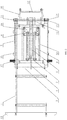
- the present invention comprises a front frame, a rear frame, a frame telescopic connecting hook, a comprehensive control arm, a comprehensive control arm shaft, a comprehensive control arm hydrocylinder and a telescopic hydrocylinder, wherein the front end of the rear frame and the front frame can be inserted telescopically relatively; the rear end of the rear frame is rotatably provided with the comprehensive control arm shaft; the comprehensive control arm comprises a principal arm, a telescopic arm and a hook arm; one end of the principal arm is hinged to the comprehensive control arm shaft, and the other end is inserted with one end of the telescopic arm telescopically relatively; the other end of the telescopic arm is connected with one end of the hook arm; the other end of the hook arm is in a hooked shape; the frame telescopic connecting hook is installed on the front frame, and hooks the telescopic arm; a cylinder body of the comprehensive control arm hydrocylinder is hinged to the rear frame;
- Both sides of the principal arm are symmetrically provided with bogie chutes respectively installed on the rear frame and telescopic with the rear frame; a sliding bogie is arranged between the bogie chutes on both sides; both sides of the sliding bogie are provided with pulleys that come into rolling contact with the bogie chutes; and the sliding bogie is connected with a power output shaft of the integrated vehicle-tractor.
- the length of the power output shaft is equal to the relatively telescopic distance of the front frame and the rear frame.
- the rear end of the rear frame is provided with a plurality of bearing seats; the comprehensive control arm shaft is rotatably installed on each bearing seat; and both ends of the comprehensive control arm shaft are respectively connected with cargo carrying hopper loading/unloading traveling pulleys convenient for loading a hopper.
- Each end of the cargo carrying hopper loading/unloading traveling pulleys is axially limited through a pulley seat stand installed on the rear frame.
- the comprehensive control arm shaft is connected with an agricultural implement lifting supporting arm for installing an agricultural implement; and the agricultural implement lifting supporting arm is connected with the turned hook arm.
- Both sides of the rear frame are provided with cargo carrying hopper traveling guide blocks for limiting the loaded hopper.
- the comprehensive control arm is positioned above the front frame and the rear frame; and one end of the hook arm is vertically connected with the other end of the telescopic arm.
- the present invention comprises a front frame 1, a rear frame 2, a frame telescopic connecting hook 4, a comprehensive control arm, a comprehensive control arm shaft 11, a comprehensive control arm hydrocylinder 8 and a telescopic hydrocylinder 9, wherein the front frame 1 and the rear frame 2 are rectangular, and can be welded by a rectangular tube or U-shaped channel steel.
- the front end of the rear frame 2 and the rear end of the front frame 1 can be inserted telescopically relatively.
- the rear end of the rear frame 2 is rotatably provided with a plurality of bearing seats 12.
- the comprehensive control arm shaft 11 is rotatably installed on each bearing seat 12.
- Both ends of the comprehensive control arm shaft 11 are respectively connected with cargo carrying hopper loading/unloading traveling pulleys 14 convenient for loading a hopper 23.
- Each end of the cargo carrying hopper loading/unloading traveling pulleys (14) is axially limited through a pulley seat stand 13 fixed to the rear end of the rear frame 2.
- the pulley seat stand 13 is in a "U" shape.
- the "U"-shaped bottom is fixedly connected to the rear frame 2.
- Open ends are respectively positioned on both sides of the axial direction of each end of the cargo carrying hopper loading/unloading traveling pulleys 14.
- the front end of the front frame 1 is fixedly connected with a frame front bar 18.
- the comprehensive control arm comprises a principal arm 5, a telescopic arm 6 and a hook arm 7; one end of the principal arm 5 is hinged to the comprehensive control arm shaft 11, and the other end is inserted with one end of the telescopic arm 6 telescopically relatively; the other end of the telescopic arm 6 is connected with one end of the hook arm 7; the other end of the hook arm 7 is in a hooked shape; An installing hole 24 used for connection is formed in the hook arm 7.
- the comprehensive control arm is positioned above the front frame and the rear frame 1, 2; and one end of the hook arm 7 is vertically connected with the other end of the telescopic arm 6.
- a frame telescopic connecting hook cross beam 3 is fixedly connected with the front frame 1, and the frame telescopic connecting hook 4 is installed on the frame telescopic connecting hook cross beam 3, and hooks the hook arm 7.
- Both opposite sides of the outer surface of the principal arm 5 are respectively provided with hydrocylinder rod connecting shafts 10.
- Both sides of the principal arm 5 are symmetrically provided with two comprehensive control arm hydrocylinders 8.
- a cylinder body of the comprehensive control arm hydrocylinder 8 at each side is hinged to the rear frame 2; a piston is hinged with the hydrocylinder rod connecting shaft 10 at the same side as the principal arm 5; and the comprehensive control arm is driven by the comprehensive control arm hydrocylinder 8 to turn around the comprehensive control arm shaft 11.
- a telescopic hydrocylinder 9 is placed in the telescopic arm 6.
- the cylinder body of the telescopic hydrocylinder 9 is connected with the inner surface of the principal arm 5.
- the piston is connected with the inner surface of the telescopic arm 6.
- the front frame and the rear frame 1, 2 are driven to be relatively telescopic through the telescopic movement of the telescopic hydrocylinder 9.
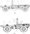
- Both sides of the principal arm 5 are symmetrically provided with bogie chutes 20 respectively installed on the rear frame 2 and telescopic with the rear frame 2; a sliding bogie 19 is arranged between the bogie chutes 20 on both sides; and both sides of the sliding bogie 19 are provided with pulleys that come into rolling contact with the bogie chutes 20.
- the sliding bogie 19 is connected with a power output shaft 21 of the integrated vehicle-tractor. The length of the power output shaft 21 is equal to the relatively telescopic distance of the front frame 1 and the rear frame 2.
- the comprehensive control arm shaft 11 is connected with an agricultural implement lifting supporting arm 16 for installing an agricultural implement.
- the agricultural implement lifting supporting arm 16 is provided with a connecting seat 22.
- the connecting seat 22 on the comprehensive control arm shaft 11 can be connected with an installing hole 24 in a hook arm 7 through a connecting rod 25.
- Both sides of the rear frame 2 are provided with cargo carrying hopper traveling guide blocks 15. After a hopper 23 is loaded on the comprehensive control arm, the hopper 23 is limited through the cargo carrying hopper traveling guide blocks 15 on both sides.
- Both sides of the rear frame 2 are respectively provided with pneumatic locking devices 17. Keyholes are formed in the inserted parts of the front frame and the rear frame 1, 2. After the front frame and the rear frame 1, 2 are telescopic to positions, the front frame and the rear frame 1, 2 are inserted into the keyholes and are automatically self-locked through the pneumatic locking devices 17, preventing the front frame and the rear frame 1, 2 from moving.
- the present invention has the operating principle that: The present invention is applied to an integrated vehicle-tractor, and has an elongated state and a shortened state.
- the telescopic arm 6 in the comprehensive control arm is hooked with the frame telescopic connecting hook 4 installed on the front frame 1.
- the cylinder body and the piston of the telescopic hydrocylinder 9 are respectively connected with the principal arm 5 and the telescopic arm 6.
- the telescopic hydrocylinder 9 is operated; power is transmitted to the comprehensive control arm shaft 11 through the principal arm 5; and the rear frame 2 is driven by the comprehensive control arm shaft 11.
- the power is transmitted to a frame telescopic connecting hook cross beam 3 through the telescopic arm 6 and the frame telescopic connecting hook 4; and the front frame 1 is driven by the frame telescopic connecting hook cross beam 3 to realize relative elongation of the front frame and the rear frame 1, 2.
- the sliding bogie 19 remains in position in the elongation process and the bogie chutes 20 move with the rear frame 2 relative to the sliding bogie 19.
- the sliding bogie 19 is connected with rear wheel brake pipelines, and vehicle illuminating lamps, direction indicator lamps, license lamps, stop lamps and other electrical lines at the tail of the vehicle.
- the comprehensive control arm can be driven by the comprehensive control arm hydrocylinders 8 to turn over.
- the frame telescopic connecting hook 4 moves down from the telescopic arm 6.
- the comprehensive control arm hydrocylinders 8 on both sides are synchronously operated, and the comprehensive control arm is driven to turn around the comprehensive control arm shaft 11.
- the comprehensive control arm hydrocylinders 8 stop the operation.
- the hopper 23 is hung to the hook on the other end of the hook arm 7.
- the comprehensive control arm hydrocylinders 8 are retracted backwards and are matched with the elongation of the telescopic arm 6.
- the hopper 23 is loaded to the frame through the comprehensive control arm.
- the cargo carrying hopper loading/unloading traveling pulleys 14 on both sides of the rear part of the rear frame 2 come into rolling contact with the hopper 23, which is convenient for loading and unloading of the hopper 23.
- the cargo carrying hopper traveling guide blocks 15 on both sides of the rear frame 2 can prevent the hopper 23 from shaking left and right, so as to limit the hopper 23.
- the comprehensive control arm hydrocylinders 8 on both sides are synchronously operated.
- the comprehensive control arm is driven to turn around the comprehensive control arm shaft 11. In the turning process, the hopper 23 is driven to gradually fall from the frame and come into contact the ground. When the hopper 23 forms an angle of 45 degrees with the principal arm 5, the hopper 23 can unload.
- the telescopic hydrocylinder 9 is operated; power is transmitted to the comprehensive control arm shaft 11 through the principal arm 5; and the rear frame 2 is driven by the comprehensive control arm shaft 11.
- the power is transmitted to a frame telescopic connecting hook cross beam 3 through the telescopic arm 6 and the frame telescopic connecting hook 4; and the front frame 1 is driven by the frame telescopic connecting hook cross beam 3 to realize relative shortening of the front frame and the rear frame 1, 2.
- the sliding bogie 19 remains in position in the shortening process and the bogie chutes 20 move with the rear frame 2 relative to the sliding bogie 19.
- the pipelines and the electrical lines on the sliding bogie 19 may not be shortened.
- various agricultural implements can also be loaded through the agricultural implement lifting supporting arm 16.
- the comprehensive control arm hydrocylinders 8 on both sides are synchronously operated.
- the comprehensive control arm is driven to turn around the comprehensive control arm shaft 11 and is matched with the shortening of the telescopic arm 6.
- the agricultural implement lifting supporting arm 16 is connected to the installing hole 24 in the hook arm 7 through the connecting rod 25, and a corresponding agricultural implement is installed on the agricultural implement lifting supporting arm 16.
Landscapes
- Engineering & Computer Science (AREA)
- Transportation (AREA)
- Mechanical Engineering (AREA)
- Chemical & Material Sciences (AREA)
- Combustion & Propulsion (AREA)
- Health & Medical Sciences (AREA)
- Public Health (AREA)
- Agricultural Machines (AREA)
- Carriers, Traveling Bodies, And Overhead Traveling Cranes (AREA)
- Forklifts And Lifting Vehicles (AREA)
Claims (8)
- Teleskoprahmen einer integrierten Fahrzeug-Zugmaschine, umfassend einen Vorderrahmen (1), einen Rückrahmen (2), einen Rahmenteleskopverbindungshaken (4), einen übergreifenden Steuerarm, eine übergreifende Steuerarmwelle (11), einen übergreifenden Steuerarmhydrozylinder (8) und einen Teleskophydrozylinder (9), wobei das Vorderende des Rückrahmens (2) und der Vorderrahmen (1) relativ zueinander teleskopisch eingeführt werden können; das rückseitige Ende des Rückrahmens (2) drehbar mit der übergreifenden Steuerarmwelle (11) bereitgestellt ist; wobei der übergreifende Steuerarm einen Hauptarm (5), einen Teleskoparm (6) und einen Hakenarm (7) umfasst; wobei ein Ende des Hauptarms (5) an die übergreifende Steuerarmwelle (11) angelenkt ist und das andere Ende mit einem Ende des Teleskoparms (6) relativ zueinander teleskopisch eingeführt ist; wobei das andere Ende des Teleskoparms (6) mit einem Ende des Hakenarms (7) verbunden ist; wobei das andere Ende des Hakenarms (7) eine Hakenform aufweist; wobei der Rahmenteleskopverbindungshaken (4) auf dem Vorderrahmen (1) angebracht ist und in den Teleskoparm (6) einhakt; wobei ein Zylinderkörper des übergreifenden Steuerarmhydrozylinders (8) an den Rückrahmen (2) angelenkt ist; wobei ein Kolben an den Hauptarm (5) angelenkt ist; wobei der übergreifende Steuerarm durch den übergreifenden Steuerarmhydrozylinder (8) angetrieben wird, um zu verschwenken; wobei der Teleskophydrozylinder (9) in dem Teleskoparm (6) angeordnet ist; wobei der Zylinderkörper auf der Innenoberfläche des Hauptarms (5) angebracht ist; wobei der Kolben mit der Innenoberfläche des Teleskoparms (6) verbunden ist; und wobei der Vorderrahmen und der Rückrahmen (1, 2) angetrieben werden, um durch die teleskopische Bewegung des Teleskophydrozylinders (9) relativ teleskopisch zu sein.
- Teleskoprahmen der integrierten Fahrzeug-Zugmaschine nach Anspruch 1, wobei beide Seiten des Hauptarms (5) symmetrisch mit Rollenbockführungen (20) bereitgestellt sind, die jeweils auf dem Rückrahmen (2) angebracht und teleskopisch mit dem Rückrahmen (2) sind; wobei ein Gleitrollenbock (19) zwischen den Rollenbockführungen (20) auf beiden Seiten angeordnet ist; wobei beide Seiten des Gleitrollenbocks (19) mit Rollen bereitgestellt sind, die in Rollkontakt mit den Rollenbockführungen (20) kommen; und wobei der Gleitrollenbock (19) mit einer Leistungsabtriebswelle (21) der integrierten Fahrzeug-Zugmaschine verbunden ist.
- Teleskoprahmen der integrierten Fahrzeug-Zugmaschine nach Anspruch 2, wobei die Länge der Leistungsabtriebswelle (21) gleich dem relativen Teleskopabstand des Vorderrahmens (1) und des Rückrahmens (2) ist.
- Teleskoprahmen der integrierten Fahrzeug-Zugmaschine nach Anspruch 1, wobei das rückseitige Ende des Rückrahmens (2) mit einer Vielzahl von Lagersitzen (12) bereitgestellt ist; wobei die übergreifende Steuerarmwelle (11) drehbar auf jedem Lagersitz (12) angebracht ist; und wobei beide Enden der übergreifenden Steuerarmwelle (11) jeweils mit Auflade-/Abladefahrrollen (14) eines eine Ladung tragenden Containers verbunden sind, die zum Aufladen eines Containers (23) geeignet sind.
- Teleskoprahmen der integrierten Fahrzeug-Zugmaschine nach Anspruch 4, wobei jedes Ende der Auflade-/Abladelaufrollen (14) eines eine Ladung tragenden Containers durch einen Rollensitzbock (13), der auf dem Rückrahmen (2) angebracht ist, axial begrenzt ist.
- Teleskoprahmen des integrierten Fahrzeug-Zugmaschine nach Anspruch 1 oder 4, wobei die übergreifende Steuerarmwelle (11) mit einem Hebe-Tragarm (16) eines landwirtschaftlichen Arbeitsgeräts zum Anbringen eines landwirtschaftlichen Arbeitsgeräts verbunden ist; und wobei der Hebe-Tragarm (16) eines landwirtschaftlichen Arbeitsgeräts mit dem geschwenkten Hakenarm (7) verbunden ist.
- Teleskoprahmen der integrierten Fahrzeug-Zugmaschine nach Anspruch 1, wobei beide Seiten des Rückrahmens (2) mit Fahrführungsblöcken (15) eines eine Ladung tragenden Containers zum Begrenzen des aufgeladenen Containers (23) bereitgestellt sind.
- Teleskoprahmen der integrierten Fahrzeug-Zugmaschine nach Anspruch 1, wobei der übergreifende Steuerarm über dem Vorderrahmen und dem Rückrahmen (1, 2) angeordnet ist; und wobei ein Ende des Hakenarms (7) vertikal mit dem anderen Ende des Teleskoparms (6) verbunden ist.
Applications Claiming Priority (2)
| Application Number | Priority Date | Filing Date | Title |
|---|---|---|---|
| CN201611122848.7A CN109398485A (zh) | 2016-12-08 | 2016-12-08 | 一种汽拖一体机伸缩机架 |
| PCT/CN2017/114682 WO2018103649A1 (zh) | 2016-12-08 | 2017-12-06 | 一种汽拖一体机伸缩机架 |
Publications (3)
| Publication Number | Publication Date |
|---|---|
| EP3552928A1 EP3552928A1 (de) | 2019-10-16 |
| EP3552928A4 EP3552928A4 (de) | 2020-09-02 |
| EP3552928B1 true EP3552928B1 (de) | 2021-08-25 |
Family
ID=62491731
Family Applications (1)
| Application Number | Title | Priority Date | Filing Date |
|---|---|---|---|
| EP17877900.5A Active EP3552928B1 (de) | 2016-12-08 | 2017-12-06 | Ausziehbarer rahmen für integrierten lkw-anhänger |
Country Status (3)
| Country | Link |
|---|---|
| EP (1) | EP3552928B1 (de) |
| CN (1) | CN109398485A (de) |
| WO (1) | WO2018103649A1 (de) |
Families Citing this family (7)
| Publication number | Priority date | Publication date | Assignee | Title |
|---|---|---|---|---|
| CN110001820A (zh) * | 2019-04-03 | 2019-07-12 | 陕西多伦科技发展有限公司 | 多式联运车辆 |
| CN110329003B (zh) * | 2019-07-03 | 2025-01-07 | 湖北纽睿德防务科技有限公司 | 一种可伸缩式轴距的底盘系统 |
| CN111606067B (zh) * | 2020-06-05 | 2022-11-01 | 周秀兰 | 一种收集作业车 |
| CN111923817B (zh) * | 2020-09-15 | 2024-09-03 | 江苏矿源环保科技有限公司 | 一种可移动罐泵一体式多功能输送运输车 |
| CN112265581B (zh) * | 2020-10-22 | 2021-09-21 | 清华大学 | 连接机构及倒ω型组合式车架 |
| CN115805995A (zh) * | 2022-11-21 | 2023-03-17 | 柳州五菱新能源汽车有限公司 | 一种采用非承载式车身的车辆、车架大梁及其制备方法 |
| CN116118638B (zh) * | 2022-12-26 | 2026-01-16 | 中国人民解放军63983部队 | 一种复合伸缩式车载连接机构 |
Family Cites Families (14)
| Publication number | Priority date | Publication date | Assignee | Title |
|---|---|---|---|---|
| JPS482567Y1 (de) * | 1967-05-02 | 1973-01-23 | ||
| JP3169242B2 (ja) * | 1991-08-29 | 2001-05-21 | ミサワホーム株式会社 | 住宅ユニット運搬車 |
| CN2355951Y (zh) * | 1998-12-25 | 1999-12-29 | 孙根才 | 多功能农用车 |
| US6558104B1 (en) * | 2000-05-18 | 2003-05-06 | Stellar Industries, Inc. | Container handling system for a vehicle |
| CN2528682Y (zh) * | 2001-10-22 | 2003-01-01 | 刘义 | 变型农用车 |
| CN2597299Y (zh) * | 2002-11-20 | 2004-01-07 | 刘惠山 | 汽车车架 |
| CN100515850C (zh) * | 2007-03-26 | 2009-07-22 | 陈海军 | 可调式重型半挂车 |
| WO2010094935A1 (en) * | 2009-02-20 | 2010-08-26 | Terry Deakin | Laterally extendible trailer for handling of loads such as containers |
| CN201559564U (zh) * | 2009-09-05 | 2010-08-25 | 烟台沪克力福特机械设备有限公司 | 一种伸缩、摆臂式拉臂钩 |
| CN201670267U (zh) * | 2010-06-08 | 2010-12-15 | 洛阳聚翔机械科技有限公司 | 可调轴距组合式拖拉机伸缩型车架 |
| CN102476653A (zh) * | 2010-11-22 | 2012-05-30 | 周明和 | 多功能农用车 |
| CN202345479U (zh) * | 2011-11-21 | 2012-07-25 | 昆山晋桦豹胶轮车制造有限公司 | 拉臂钩式煤矿运输车 |
| CN205059371U (zh) * | 2015-10-14 | 2016-03-02 | 湖北江山专用汽车有限公司 | 一种自动控制安全支撑装置 |
| CN206255069U (zh) * | 2016-12-08 | 2017-06-16 | 周明和 | 汽拖一体机伸缩机架 |
-
2016
- 2016-12-08 CN CN201611122848.7A patent/CN109398485A/zh active Pending
-
2017
- 2017-12-06 WO PCT/CN2017/114682 patent/WO2018103649A1/zh not_active Ceased
- 2017-12-06 EP EP17877900.5A patent/EP3552928B1/de active Active
Also Published As
| Publication number | Publication date |
|---|---|
| CN109398485A (zh) | 2019-03-01 |
| EP3552928A4 (de) | 2020-09-02 |
| WO2018103649A1 (zh) | 2018-06-14 |
| EP3552928A1 (de) | 2019-10-16 |
Similar Documents
| Publication | Publication Date | Title |
|---|---|---|
| EP3552928B1 (de) | Ausziehbarer rahmen für integrierten lkw-anhänger | |
| US4645405A (en) | Roll-off container handling mechanism | |
| US3682333A (en) | Self-unloading vehicle | |
| MX2014002022A (es) | Montaje elevador de eje. | |
| US3667631A (en) | Hydraulic utility lift for trucks | |
| US6042328A (en) | Lifting device | |
| EP2103458A1 (de) | Fahrzeugkupplung | |
| US2119800A (en) | Telescoping extension for trucks and trailers | |
| US2991894A (en) | Spare tire carriers | |
| US1941400A (en) | Wrecking car | |
| US3557980A (en) | Vehicle for transporting loads | |
| KR101004281B1 (ko) | 자동 물림식 덤프 트레일러 | |
| CN207890532U (zh) | 一种链条带动的自行走隧道施工台车 | |
| US8740249B1 (en) | Combine header transport trailer | |
| CN206255069U (zh) | 汽拖一体机伸缩机架 | |
| US2603365A (en) | Log loading and unloading apparatus | |
| US3417890A (en) | Trailer for towing cars | |
| US3348712A (en) | Trailer | |
| EP1795436A3 (de) | Aufliegeranhänger mit Schwanenhals | |
| KR20140137938A (ko) | 차량 장착용 크레인 | |
| KR20190053311A (ko) | 견인식 트레일러 | |
| KR20100000622U (ko) | 견인차량의 크레인 이동장치 | |
| KR102004722B1 (ko) | 암롤차량용 덤핑 및 하역장치 | |
| CN204055501U (zh) | 铰接式举升挂车 | |
| GB640885A (en) | Improvements in or relating to trucks and like load-carrying vehicles |
Legal Events
| Date | Code | Title | Description |
|---|---|---|---|
| STAA | Information on the status of an ep patent application or granted ep patent |
Free format text: STATUS: THE INTERNATIONAL PUBLICATION HAS BEEN MADE |
|
| PUAI | Public reference made under article 153(3) epc to a published international application that has entered the european phase |
Free format text: ORIGINAL CODE: 0009012 |
|
| STAA | Information on the status of an ep patent application or granted ep patent |
Free format text: STATUS: REQUEST FOR EXAMINATION WAS MADE |
|
| 17P | Request for examination filed |
Effective date: 20190125 |
|
| AK | Designated contracting states |
Kind code of ref document: A1 Designated state(s): AL AT BE BG CH CY CZ DE DK EE ES FI FR GB GR HR HU IE IS IT LI LT LU LV MC MK MT NL NO PL PT RO RS SE SI SK SM TR |
|
| AX | Request for extension of the european patent |
Extension state: BA ME |
|
| DAV | Request for validation of the european patent (deleted) | ||
| DAX | Request for extension of the european patent (deleted) | ||
| A4 | Supplementary search report drawn up and despatched |
Effective date: 20200731 |
|
| RIC1 | Information provided on ipc code assigned before grant |
Ipc: B62D 21/14 20060101ALI20200724BHEP Ipc: B60P 1/64 20060101ALI20200724BHEP Ipc: B62D 21/02 20060101AFI20200724BHEP |
|
| GRAP | Despatch of communication of intention to grant a patent |
Free format text: ORIGINAL CODE: EPIDOSNIGR1 |
|
| STAA | Information on the status of an ep patent application or granted ep patent |
Free format text: STATUS: GRANT OF PATENT IS INTENDED |
|
| RIC1 | Information provided on ipc code assigned before grant |
Ipc: B60P 3/42 20060101ALI20210401BHEP Ipc: B60P 1/64 20060101ALI20210401BHEP Ipc: B62D 21/14 20060101ALI20210401BHEP Ipc: B62D 21/02 20060101AFI20210401BHEP |
|
| INTG | Intention to grant announced |
Effective date: 20210422 |
|
| GRAS | Grant fee paid |
Free format text: ORIGINAL CODE: EPIDOSNIGR3 |
|
| GRAA | (expected) grant |
Free format text: ORIGINAL CODE: 0009210 |
|
| STAA | Information on the status of an ep patent application or granted ep patent |
Free format text: STATUS: THE PATENT HAS BEEN GRANTED |
|
| AK | Designated contracting states |
Kind code of ref document: B1 Designated state(s): AL AT BE BG CH CY CZ DE DK EE ES FI FR GB GR HR HU IE IS IT LI LT LU LV MC MK MT NL NO PL PT RO RS SE SI SK SM TR |
|
| REG | Reference to a national code |
Ref country code: CH Ref legal event code: EP |
|
| REG | Reference to a national code |
Ref country code: IE Ref legal event code: FG4D Ref country code: AT Ref legal event code: REF Ref document number: 1423530 Country of ref document: AT Kind code of ref document: T Effective date: 20210915 |
|
| REG | Reference to a national code |
Ref country code: DE Ref legal event code: R096 Ref document number: 602017044940 Country of ref document: DE |
|
| REG | Reference to a national code |
Ref country code: LT Ref legal event code: MG9D |
|
| REG | Reference to a national code |
Ref country code: NL Ref legal event code: MP Effective date: 20210825 |
|
| REG | Reference to a national code |
Ref country code: AT Ref legal event code: MK05 Ref document number: 1423530 Country of ref document: AT Kind code of ref document: T Effective date: 20210825 |
|
| PG25 | Lapsed in a contracting state [announced via postgrant information from national office to epo] |
Ref country code: PT Free format text: LAPSE BECAUSE OF FAILURE TO SUBMIT A TRANSLATION OF THE DESCRIPTION OR TO PAY THE FEE WITHIN THE PRESCRIBED TIME-LIMIT Effective date: 20211227 Ref country code: NO Free format text: LAPSE BECAUSE OF FAILURE TO SUBMIT A TRANSLATION OF THE DESCRIPTION OR TO PAY THE FEE WITHIN THE PRESCRIBED TIME-LIMIT Effective date: 20211125 Ref country code: LT Free format text: LAPSE BECAUSE OF FAILURE TO SUBMIT A TRANSLATION OF THE DESCRIPTION OR TO PAY THE FEE WITHIN THE PRESCRIBED TIME-LIMIT Effective date: 20210825 Ref country code: BG Free format text: LAPSE BECAUSE OF FAILURE TO SUBMIT A TRANSLATION OF THE DESCRIPTION OR TO PAY THE FEE WITHIN THE PRESCRIBED TIME-LIMIT Effective date: 20211125 Ref country code: AT Free format text: LAPSE BECAUSE OF FAILURE TO SUBMIT A TRANSLATION OF THE DESCRIPTION OR TO PAY THE FEE WITHIN THE PRESCRIBED TIME-LIMIT Effective date: 20210825 Ref country code: SE Free format text: LAPSE BECAUSE OF FAILURE TO SUBMIT A TRANSLATION OF THE DESCRIPTION OR TO PAY THE FEE WITHIN THE PRESCRIBED TIME-LIMIT Effective date: 20210825 Ref country code: RS Free format text: LAPSE BECAUSE OF FAILURE TO SUBMIT A TRANSLATION OF THE DESCRIPTION OR TO PAY THE FEE WITHIN THE PRESCRIBED TIME-LIMIT Effective date: 20210825 Ref country code: HR Free format text: LAPSE BECAUSE OF FAILURE TO SUBMIT A TRANSLATION OF THE DESCRIPTION OR TO PAY THE FEE WITHIN THE PRESCRIBED TIME-LIMIT Effective date: 20210825 Ref country code: FI Free format text: LAPSE BECAUSE OF FAILURE TO SUBMIT A TRANSLATION OF THE DESCRIPTION OR TO PAY THE FEE WITHIN THE PRESCRIBED TIME-LIMIT Effective date: 20210825 Ref country code: ES Free format text: LAPSE BECAUSE OF FAILURE TO SUBMIT A TRANSLATION OF THE DESCRIPTION OR TO PAY THE FEE WITHIN THE PRESCRIBED TIME-LIMIT Effective date: 20210825 |
|
| PG25 | Lapsed in a contracting state [announced via postgrant information from national office to epo] |
Ref country code: PL Free format text: LAPSE BECAUSE OF FAILURE TO SUBMIT A TRANSLATION OF THE DESCRIPTION OR TO PAY THE FEE WITHIN THE PRESCRIBED TIME-LIMIT Effective date: 20210825 Ref country code: LV Free format text: LAPSE BECAUSE OF FAILURE TO SUBMIT A TRANSLATION OF THE DESCRIPTION OR TO PAY THE FEE WITHIN THE PRESCRIBED TIME-LIMIT Effective date: 20210825 Ref country code: GR Free format text: LAPSE BECAUSE OF FAILURE TO SUBMIT A TRANSLATION OF THE DESCRIPTION OR TO PAY THE FEE WITHIN THE PRESCRIBED TIME-LIMIT Effective date: 20211126 |
|
| PG25 | Lapsed in a contracting state [announced via postgrant information from national office to epo] |
Ref country code: NL Free format text: LAPSE BECAUSE OF FAILURE TO SUBMIT A TRANSLATION OF THE DESCRIPTION OR TO PAY THE FEE WITHIN THE PRESCRIBED TIME-LIMIT Effective date: 20210825 |
|
| PG25 | Lapsed in a contracting state [announced via postgrant information from national office to epo] |
Ref country code: DK Free format text: LAPSE BECAUSE OF FAILURE TO SUBMIT A TRANSLATION OF THE DESCRIPTION OR TO PAY THE FEE WITHIN THE PRESCRIBED TIME-LIMIT Effective date: 20210825 |
|
| REG | Reference to a national code |
Ref country code: DE Ref legal event code: R097 Ref document number: 602017044940 Country of ref document: DE |
|
| PG25 | Lapsed in a contracting state [announced via postgrant information from national office to epo] |
Ref country code: SM Free format text: LAPSE BECAUSE OF FAILURE TO SUBMIT A TRANSLATION OF THE DESCRIPTION OR TO PAY THE FEE WITHIN THE PRESCRIBED TIME-LIMIT Effective date: 20210825 Ref country code: SK Free format text: LAPSE BECAUSE OF FAILURE TO SUBMIT A TRANSLATION OF THE DESCRIPTION OR TO PAY THE FEE WITHIN THE PRESCRIBED TIME-LIMIT Effective date: 20210825 Ref country code: RO Free format text: LAPSE BECAUSE OF FAILURE TO SUBMIT A TRANSLATION OF THE DESCRIPTION OR TO PAY THE FEE WITHIN THE PRESCRIBED TIME-LIMIT Effective date: 20210825 Ref country code: EE Free format text: LAPSE BECAUSE OF FAILURE TO SUBMIT A TRANSLATION OF THE DESCRIPTION OR TO PAY THE FEE WITHIN THE PRESCRIBED TIME-LIMIT Effective date: 20210825 Ref country code: CZ Free format text: LAPSE BECAUSE OF FAILURE TO SUBMIT A TRANSLATION OF THE DESCRIPTION OR TO PAY THE FEE WITHIN THE PRESCRIBED TIME-LIMIT Effective date: 20210825 Ref country code: AL Free format text: LAPSE BECAUSE OF FAILURE TO SUBMIT A TRANSLATION OF THE DESCRIPTION OR TO PAY THE FEE WITHIN THE PRESCRIBED TIME-LIMIT Effective date: 20210825 |
|
| PLBE | No opposition filed within time limit |
Free format text: ORIGINAL CODE: 0009261 |
|
| STAA | Information on the status of an ep patent application or granted ep patent |
Free format text: STATUS: NO OPPOSITION FILED WITHIN TIME LIMIT |
|
| PG25 | Lapsed in a contracting state [announced via postgrant information from national office to epo] |
Ref country code: MC Free format text: LAPSE BECAUSE OF FAILURE TO SUBMIT A TRANSLATION OF THE DESCRIPTION OR TO PAY THE FEE WITHIN THE PRESCRIBED TIME-LIMIT Effective date: 20210825 Ref country code: IT Free format text: LAPSE BECAUSE OF FAILURE TO SUBMIT A TRANSLATION OF THE DESCRIPTION OR TO PAY THE FEE WITHIN THE PRESCRIBED TIME-LIMIT Effective date: 20210825 |
|
| REG | Reference to a national code |
Ref country code: CH Ref legal event code: PL |
|
| 26N | No opposition filed |
Effective date: 20220527 |
|
| PG25 | Lapsed in a contracting state [announced via postgrant information from national office to epo] |
Ref country code: SI Free format text: LAPSE BECAUSE OF FAILURE TO SUBMIT A TRANSLATION OF THE DESCRIPTION OR TO PAY THE FEE WITHIN THE PRESCRIBED TIME-LIMIT Effective date: 20210825 |
|
| REG | Reference to a national code |
Ref country code: BE Ref legal event code: MM Effective date: 20211231 |
|
| PG25 | Lapsed in a contracting state [announced via postgrant information from national office to epo] |
Ref country code: LU Free format text: LAPSE BECAUSE OF NON-PAYMENT OF DUE FEES Effective date: 20211206 Ref country code: IE Free format text: LAPSE BECAUSE OF NON-PAYMENT OF DUE FEES Effective date: 20211206 |
|
| PG25 | Lapsed in a contracting state [announced via postgrant information from national office to epo] |
Ref country code: BE Free format text: LAPSE BECAUSE OF NON-PAYMENT OF DUE FEES Effective date: 20211231 |
|
| PG25 | Lapsed in a contracting state [announced via postgrant information from national office to epo] |
Ref country code: LI Free format text: LAPSE BECAUSE OF NON-PAYMENT OF DUE FEES Effective date: 20211231 Ref country code: CH Free format text: LAPSE BECAUSE OF NON-PAYMENT OF DUE FEES Effective date: 20211231 |
|
| PG25 | Lapsed in a contracting state [announced via postgrant information from national office to epo] |
Ref country code: CY Free format text: LAPSE BECAUSE OF FAILURE TO SUBMIT A TRANSLATION OF THE DESCRIPTION OR TO PAY THE FEE WITHIN THE PRESCRIBED TIME-LIMIT Effective date: 20210825 |
|
| PG25 | Lapsed in a contracting state [announced via postgrant information from national office to epo] |
Ref country code: HU Free format text: LAPSE BECAUSE OF FAILURE TO SUBMIT A TRANSLATION OF THE DESCRIPTION OR TO PAY THE FEE WITHIN THE PRESCRIBED TIME-LIMIT; INVALID AB INITIO Effective date: 20171206 |
|
| REG | Reference to a national code |
Ref country code: GB Ref legal event code: 732E Free format text: REGISTERED BETWEEN 20230921 AND 20230927 |
|
| REG | Reference to a national code |
Ref country code: DE Ref legal event code: R082 Ref document number: 602017044940 Country of ref document: DE Representative=s name: MEWBURN ELLIS LLP, DE Ref country code: DE Ref legal event code: R081 Ref document number: 602017044940 Country of ref document: DE Owner name: ZHOU, MINGHE, DANDONG, CN Free format text: FORMER OWNER: TECHNOLOGY RESEARCH AND DEVELOPMENT CENTER OF LIAONING DANDONG, DANDONG, LIAONING, CN Ref country code: DE Ref legal event code: R081 Ref document number: 602017044940 Country of ref document: DE Owner name: JILIN JUNDE AGRICULTURAL MACHINERY CO., LTD., CN Free format text: FORMER OWNER: TECHNOLOGY RESEARCH AND DEVELOPMENT CENTER OF LIAONING DANDONG, DANDONG, LIAONING, CN |
|
| PG25 | Lapsed in a contracting state [announced via postgrant information from national office to epo] |
Ref country code: MK Free format text: LAPSE BECAUSE OF FAILURE TO SUBMIT A TRANSLATION OF THE DESCRIPTION OR TO PAY THE FEE WITHIN THE PRESCRIBED TIME-LIMIT Effective date: 20210825 |
|
| PG25 | Lapsed in a contracting state [announced via postgrant information from national office to epo] |
Ref country code: TR Free format text: LAPSE BECAUSE OF FAILURE TO SUBMIT A TRANSLATION OF THE DESCRIPTION OR TO PAY THE FEE WITHIN THE PRESCRIBED TIME-LIMIT Effective date: 20210825 |
|
| PG25 | Lapsed in a contracting state [announced via postgrant information from national office to epo] |
Ref country code: MT Free format text: LAPSE BECAUSE OF FAILURE TO SUBMIT A TRANSLATION OF THE DESCRIPTION OR TO PAY THE FEE WITHIN THE PRESCRIBED TIME-LIMIT Effective date: 20210825 |
|
| PGFP | Annual fee paid to national office [announced via postgrant information from national office to epo] |
Ref country code: GB Payment date: 20241218 Year of fee payment: 8 |
|
| PGFP | Annual fee paid to national office [announced via postgrant information from national office to epo] |
Ref country code: FR Payment date: 20241219 Year of fee payment: 8 |
|
| PGFP | Annual fee paid to national office [announced via postgrant information from national office to epo] |
Ref country code: DE Payment date: 20241218 Year of fee payment: 8 |