EP3552825A1 - Vollautomatische kaltprägungsmaschine vom drehradtyp - Google Patents
Vollautomatische kaltprägungsmaschine vom drehradtyp Download PDFInfo
- Publication number
- EP3552825A1 EP3552825A1 EP16923430.9A EP16923430A EP3552825A1 EP 3552825 A1 EP3552825 A1 EP 3552825A1 EP 16923430 A EP16923430 A EP 16923430A EP 3552825 A1 EP3552825 A1 EP 3552825A1
- Authority
- EP
- European Patent Office
- Prior art keywords
- stage
- conveyor belt
- post
- foil
- stamping foil
- Prior art date
- Legal status (The legal status is an assumption and is not a legal conclusion. Google has not performed a legal analysis and makes no representation as to the accuracy of the status listed.)
- Granted
Links
Images


Classifications
-
- B—PERFORMING OPERATIONS; TRANSPORTING
- B41—PRINTING; LINING MACHINES; TYPEWRITERS; STAMPS
- B41F—PRINTING MACHINES OR PRESSES
- B41F16/00—Transfer printing apparatus
- B41F16/0006—Transfer printing apparatus for printing from an inked or preprinted foil or band
- B41F16/002—Presses of the rotary type
- B41F16/0033—Presses of the rotary type with means for applying print under pressure only, e.g. using pressure sensitive adhesive
-
- B—PERFORMING OPERATIONS; TRANSPORTING
- B41—PRINTING; LINING MACHINES; TYPEWRITERS; STAMPS
- B41G—APPARATUS FOR BRONZE PRINTING, LINE PRINTING, OR FOR BORDERING OR EDGING SHEETS OR LIKE ARTICLES; AUXILIARY FOR PERFORATING IN CONJUNCTION WITH PRINTING
- B41G1/00—Apparatus for bronze printing or for like operations
- B41G1/04—Apparatus for bronze printing or for like operations cylinder type
Definitions
- the utility model relates to the technical field of printing equipment for special printing on substrates and in particular to a cylinder type fully automatic cold foil machine.
- the cold foil technology combines a conventional printing technology and bonding technology, which not only increases the variability of printing design, but also can be used to produce products which have perfect effects of completing cold foil and embossing in one time.
- the cold foil technology is widely used in the production of packaging boxes, tiny poster calendars, anti-counterfeit labels, various securities, and the like.
- the cold foil technology can not only reduce production costs and improve production efficiency, but also re-create the added value of products. Therefore, the cold foil technology has gradually become a new development trend in printing technology.
- an objective of the utility model is to provide a cylinder type fully automatic cold foil machine.
- a cylinder type fully automatic cold foil machine comprising:
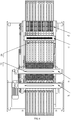
- the stamping foil mounting device comprises at least one multi-stage guiding roller set located above the front-stage conveyor belt in the front-rear direction, each of the multi-stage guiding roller sets comprises a slip-type air shaft on top for mounting a roll of stamping foil and a bottom slip-type air shaft, and the bottom slip-type air shaft is located under the top slip-type air shaft; the top slip-type air shaft and the bottom slip-type air shaft are each correspondingly provided with a tension guide roller for performing tension and guiding control on the stamping foil, and a discharging guide roller is disposed between the tension guide roller corresponding to the bottom slip-type air shaft and the front foil pressing roller; the stamping foil on the top slip-type air shaft is drawn to be between the rotary main cylinder and the front foil pressing roller through the tension guide roller corresponding to the top slip-type air shaft, the tension guide roller corresponding to the bottom slip-type air shaft and the discharging guide roller; and the stamping foil on the bottom slip-type air shaft is drawn to be between the
- the conveyor belt mechanism further comprises a single-stage roll matching one of the multi-stage roll sets for use;
- the single-stage roll comprises a single-stage slip-type air shaft parallel to the top slip-type air shaft in a left-right mode;
- the single-stage slip-type air shaft is correspondingly provided with at least one single-stage tension guide roller;
- stamping foil on the single-stage slip-type air shaft is drawn to be between the rotary main cylinder and the front foil pressing roller through the single-stage tension guide roller, the tension guide roller corresponding to the bottom slip-type air shaft and the discharging guide roller.
- the front foil pressing roller and the rear foil pressing roller each comprise a roller pneumatic lifting cylinder mounted in the machine frame body and located below the conveyor belt mechanism, a pressing rubber roller placed above the conveyor belt mechanism and tangential to the rotary main cylinder, and a lifting swing arm that is connected to the machine frame body through a shaft, with the bottom end connected with the rubber roll lifting cylinder and the top end connected with the pressing rubber rollers.
- the conveyor belt mechanism further comprises a front connecting conveyor belt that has the left end connected to the machine frame body through a shaft and is located on the feeding side of the front-stage conveyor belt and a rear connecting conveyor belt that has the right end connected to the machine frame body through a shaft and is located on the discharging side of the post-stage conveyor belt;
- the synchronous belt set comprises a first front-stage synchronous belt, a second front-stage synchronous belt, a first front-stage synchronous wheel, a second front-stage synchronous wheel, a front-stage tensioning wheel, a first post-stage synchronous belt, a second post-stage synchronous belt, a third post-stage synchronous belt, a first post-stage synchronous wheel, a second post-stage synchronous wheel, a third post-stage synchronous wheel, and a post-stage tensioning wheel;
- the front-stage tensioning wheel and the second front-stage synchronous wheel are sequentially distributed from top to bottom below the feeding end of the front-stage conveyor belt, the first front-stage synchronous wheel is
- the machine frame body is internally provided with a front-stage overturning cylinder and a post-stage overturning cylinder
- a power shaft of the front-stage overturning cylinder is connected to the bottom surface of the front connecting conveyor belt
- the front-stage overturning cylinder drives the front connecting conveyor belt to perform a 90-degree overturning movement relative to the front-stage conveyor belt
- a power shaft of the post-stage overturning cylinder is connected to the bottom surface of the rear connecting conveyor belt
- the post-stage overturning cylinder drives the rear connecting conveyor belt to perform a 90-degree overturning movement relative to the post-stage conveyor belt.
- the vacuum suction mechanism comprises a vacuum pump, a vacuum accumulator, and a plurality of air suction pipes; the vacuum pump and the vacuum accumulator are mounted in the machine frame body and located below the conveyor belt mechanism; the vacuum accumulator is connected with the vacuum pump, the tail end of each of the air suction pipes is connected with the vacuum pump, the head end of each of the air suction pipes is respectively correspondingly connected to the bottom surfaces of the front connecting conveyor belt, the front-stage conveyor belt, the post-stage conveyor belt, and the rear connecting conveyor belt.
- the cylinder type fully automatic cold foil machine further comprises a cooling pipe assembly for supplying a cooling medium
- the cooling pipe assembly comprises cooling pipes distributed by passing through the rotating main cylinder , the pre-curing device, the in-printing curing device and the post-curing device, and cooling supporting plates disposed above or below the front-stage conveyor belt and the post-stage conveyor belt; and the pre-curing device and the post-curing device are located within the contour coverage of the corresponding cooling supporting plates respectively.
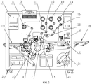
- a foiling portion of the utility model adopts a structure form of matching the rotating main cylinder with the two foil pressing rollers, which can carry out two-side press fit transfer processing of stamping foil and a printing substrate; at the same time, glue on the printing substrate cured at different degrees in the pre-curing , in-printing curing and post-curing stages by using the three curing devices, which can effectively ensure the integrity of foil patterns and a foiling effect; and the rotary cylinder type fully automatic cold foil machine is simple and compact in structure and can ensure effects of foiling processes such as , cold foil ,raised cold foil, cast and cure and raised cast and cure.
- the entire machine can be seamlessly connected to other printing devices and can implement on-line running-form one-time printing of printed products such as sheets, films, and paper, without the need for additional process settings, thereby effectively improving production efficiency.
- the machine has a strong practical value and marketing value.
- the machine also has the following effects: 1.Through the arranged seal box b, not only can a relatively closed printing environment be formed on the machine to prevent pollution from the external environment, but also a printed product in the seal box b can be air-cooled through the fresh air port 3 and the air outlet 4 as needed, thereby effectively solving the problem of deformation of the printing substrate A or the final printed product easily caused by the overtemperature of the pre-curing device e, the in-printing curing device n and the post-curing device k. 2.
- the printing substrate A or the finished product can be adsorbed to the conveyor belt mechanism c, thereby effectively preventing the printing substrate A or the finished product from being deviated or deformed in the conveying process.
- the structural design of the stamping foil mounting device f enables the whole machine to mount a plurality of different stamping foil rolls according to the number of printed patterns to meet the requirements for the number of printed patterns. 4. Components in the whole machine can be under centralized control through the electrical control assembly, which provides the hardware basis for the digital automatic control of the machine, operation smoothness, operation accuracy, and the like.
- the stamping foil mounting device f of the embodiment comprises at least one multi-stage roll set disposed above the front-stage conveyor belt 5 in the front-rear direction, each of the multi-stage roll sets comprises a top slip-type air shaft 10 for storing a stamping foil roll and a bottom slip-type air shaft 11, and the bottom slip-type air shaft 11 is located under the top slip-type air shaft 10; the top slip-type air shaft 10 and the bottom slip-type air shaft 11 are each correspondingly provided with a tension guide roller 12 for performing tension and guiding control on the stamping foil B, and a discharging guide roller 13 is disposed between the tension guide roller 12 corresponding to the bottom slip-type air shaft 11 and the front foil pressing roller 8.
- stamping foil B when the stamping foil B is pulled, the stamping foil B on the top slip-type air shaft 10 is pulled to be between the rotating main cylinder 7 and the front foil pressisng roller 8 through the tension guide roller 12 corresponding to the top slip-type air shaft 10, the tension guide roller 12 corresponding to the bottom slip-type air shaft 11 and the discharging guide roller 13, and stamping foil B on the bottom slip-type air shaft 11 is pulled to be between the rotating main cylinder 7 and the front foil pressing roller 8 through the tension guide roller 12 corresponding to the bottom slip-type air shaft 11 and the discharging guide roller 13.
- a plurality of slip-type air shafts may be arranged in the up-and-down direction between the top slip-type air shaft 10 and the bottom slip-type air shaft 11 (correspondingly, each of the slip-type air shafts is correspondingly provided with a tension guide roller shaft); after the stamping foil B located on the upper slip-type air shaft is guided out by the corresponding tension guide roller shaft, the stamping foil B can be guided out through the tension guide roller shaft corresponding to the lower slip-type air shaft, and is finally guided to be between the rotating main cylinder 7 and the front foil pressing roller 8 through the discharging guide roller 13.
- the stamping foil mounting device f of the embodiment further includes a single-stage roll matching one of the multi-stage roll sets for use;
- the single-stage roll comprises a single-stage slip-type air shaft 14 parallel to the top slip-type air shaft 10 in a left-right mode;
- the single-stage slip-type air shaft 14 is correspondingly provided with at least one single-stage tension guide roller 15;
- stamping foil B on the single-stage slip-type air shaft 14 is pulled to be between the rotating main cylinder 7 and the front foil pressing roller 8 through the single-stage tension guide roller 15, the tension guide roller 12 corresponding to the bottom slip-type air shaft 11 and the discharging guide roller 13.
- the stamping foil mounting device f can simultaneously assemble a plurality of stamping foils with no need to perform repeated printing on the printing substrate A many times, which is favorable for improving the printing production efficiency of the entire machine.
- the front foil pressing roller 8 and the rear fol 9 of the embodiment each comprise a rubber roll lifting cylinder 16 mounted in the machine frame body a and located below the conveyor belt mechanism c, a coining rubber roll placed above the conveyor belt mechanism c and tangential to the rotating main cylinder 7, and a lifting swing arm 17 that is connected to the machine frame body a through a shaft, with the bottom end connected with the rubber roll lifting cylinder 16 and the top end connected with the coining rubber roll.
- the coining rubber roll can be away from or close to the rotating main cylinder 7 by means of the swing effect of the lifting swing arm 17, so that the bearing pressure is regulated by using the coining rubber roll, and it is ensured that the stamping foil B can be transferred and adhere to the surface of a pattern of the printing substrate A.
- the conveyor belt mechanism c of the embodiment further includes a front connecting conveyor belt 18 that has the left end connected to the machine frame body a through a shaft and is located on the feeding side of the front-stage conveyor belt 5 and a rear connecting conveyor belt 19 that has the right end connected to the machine frame body a through a shaft and is located on the discharging side of the post-stage conveyor belt 6;
- the synchronous belt set comprises a first front-stage synchronous belt 200, a second front-stage synchronous belt 201, a first front-stage synchronous wheel 202, a second front-stage synchronous wheel 203, a front-stage tensioning wheel 204, a first post-stage synchronous belt 205, a second post-stage synchronous belt 206, a third post-stage synchronous belt 207, a first post-stage synchronous wheel 208, a second post-stage synchronous wheel 209
- the rotating main cylinder 7 can be used as a driving wheel of the whole synchronous belt set, the synchronous movement of each conveyor belt can be achieved by the cooperation of each of the synchronous belts and each of the synchronous wheels, thereby ensuring that the printing substrate A and the finished product are conveyed stably; meanwhile, the front connecting conveyor belt 18 can be in butt joint with a front-end process processing device C to receive the printing substrate A conveyed by the front-end process processing device C, and the rear connecting conveyor belt 19 can be in butt joint with a post-stage process processing device D to output the finished product having undergone cold foil processing. Therefore, the entire machine can be seamlessly connected to other printing devices and can implement on-line running-form one-time printing of printed products such as sheets, films, and paper, without the need for additional process settings, thereby effectively improving production efficiency.
- the machine frame body a is internally provided with a front-stage overturning cylinder 21 and a post-stage overturning cylinder 22, a power shaft of the front-stage overturning cylinder 21 is connected to the bottom surface of the front connecting conveyor belt 18, and the front-stage overturning cylinder 21 drives the front connecting conveyor belt 18 to perform a 90-degree overturning movement relative to the front-stage conveyor belt 5; a power shaft of the post-stage overturning cylinder 22 is connected to the bottom surface of the rear connecting conveyor belt 19, and the post-stage overturning cylinder 22 drives the rear connecting conveyor belt 19 to perform a 90-degree overturning movement relative to the post-stage conveyor belt 6. Therefore, depending on the actual production needs, the corresponding conveying belt can be overturned downwards for folding and storage or overturned upwards for unfolding and connection by means of the overturning cylinders.
- the vacuum suction mechanism m of the embodiment comprises a vacuum pump 23, a vacuum accumulator (not shown in the figure), and a plurality of air suction pipes (not shown in the figure); the vacuum pump 23 and the vacuum accumulator are mounted in the machine frame body a and located below the conveyor belt mechanism c; the vacuum accumulator is connected with the vacuum pump 23, the tail end of each of the air suction pipes is connected with the vacuum pump 23, the head end of each of the air suction pipes is respectively correspondingly connected to the bottom surfaces of the front connecting conveyor belt 18, the front-stage conveyor belt 5, the post-stage conveyor belt 6, and the rear connecting conveyor belt 19 (the above conveyor belts are each provided with a negative pressure air pipe 24 in butt joint with the head end of the air suction pipe).
- negative pressure regions can be formed on each conveyor belt by using negative pressure power generated by the vacuum pump 23, so that the printing substrate A and even the finished product can be adsorbed to the corresponding conveyor belt, and particularly it can be ensured that the printing substrate A is not subjected to problems such as deviation or deformation in the conveying process.
- the cold foil machine of the embodiment further includes a cooling pipe assembly for supplying a cooling medium (such as cooling oil, cooling water, or cold air), the cooling pipe assembly comprises cooling pipes 25 distributed by passing through the rotating main cylinder 7, the pre-curing device e, the in-printing curing device n and the post-curing device k, and cooling supporting plates 26 disposed above or below the front-stage conveyor belt 5 and the post-stage conveyor belt 6; and the pre-curing device e and the post-curing device k are located within the contour coverage of the corresponding cooling supporting plates 26 respectively.
- a cooling medium such as cooling oil, cooling water, or cold air
- the provided cooling pipe assembly can provide an auxiliary cooling function for an irradiation area of the curing device, avoiding excessive environmental temperature in the area; at the same time, performance improvement can be performed on each curing device, for example, a stepless dimming lamp is used as a core illumination element.
- the cold foil machine of the embodiment can adopt the following usage and control principles, that is:
Landscapes
- Engineering & Computer Science (AREA)
- Mechanical Engineering (AREA)
- Labeling Devices (AREA)
- Supply, Installation And Extraction Of Printed Sheets Or Plates (AREA)
- Press Drives And Press Lines (AREA)
Applications Claiming Priority (1)
| Application Number | Priority Date | Filing Date | Title |
|---|---|---|---|
| PCT/CN2016/109061 WO2018103046A1 (zh) | 2016-12-08 | 2016-12-08 | 一种转轮式全自动冷烫机 |
Publications (3)
| Publication Number | Publication Date |
|---|---|
| EP3552825A1 true EP3552825A1 (de) | 2019-10-16 |
| EP3552825A4 EP3552825A4 (de) | 2020-01-15 |
| EP3552825B1 EP3552825B1 (de) | 2020-09-02 |
Family
ID=62490625
Family Applications (1)
| Application Number | Title | Priority Date | Filing Date |
|---|---|---|---|
| EP16923430.9A Active EP3552825B1 (de) | 2016-12-08 | 2016-12-08 | Vollautomatische kaltprägungsmaschine vom drehradtyp |
Country Status (2)
| Country | Link |
|---|---|
| EP (1) | EP3552825B1 (de) |
| WO (1) | WO2018103046A1 (de) |
Families Citing this family (2)
| Publication number | Priority date | Publication date | Assignee | Title |
|---|---|---|---|---|
| CN114308517B (zh) * | 2021-12-10 | 2023-08-29 | 迅展机械(无锡)有限公司 | 一种铝片涂装机 |
| CN119704916A (zh) * | 2025-03-03 | 2025-03-28 | 福州前景彩印有限公司 | 一种彩印方法以及彩盒生产用彩印装置 |
Family Cites Families (12)
| Publication number | Priority date | Publication date | Assignee | Title |
|---|---|---|---|---|
| JP2007111873A (ja) * | 2005-10-18 | 2007-05-10 | Mitsubishi Heavy Ind Ltd | 印刷機の水性ニス乾燥装置及び印刷機 |
| JP2010513075A (ja) * | 2006-12-20 | 2010-04-30 | マンローラント・アーゲー | モジュール式フィルムユニット |
| CN101092073B (zh) * | 2007-07-25 | 2011-08-31 | 吴德明 | 带有定位功能的多用途印刷表面加工系统与工艺 |
| CN101486270B (zh) * | 2009-02-11 | 2010-07-28 | 李钟荣 | 一种可对印材表面进行多种处理的设备 |
| CN101863160B (zh) * | 2009-04-15 | 2011-09-07 | 武汉虹之彩包装印刷有限公司 | 卷筒印刷整饰生产设备 |
| CN102452214A (zh) * | 2010-10-20 | 2012-05-16 | 海德堡印刷机械股份公司 | 具有磁场干燥装置的转移装置 |
| DE102012021819A1 (de) * | 2012-11-07 | 2014-05-08 | Heidelberger Druckmaschinen Ag | Verfahren zum Beschichten von Bogen mit einem Film in einer Druckmaschine |
| CN204077059U (zh) * | 2014-09-17 | 2015-01-07 | 无锡市龙创印刷科技有限公司 | 一种定位冷烫机 |
| CN105856819B (zh) * | 2016-04-25 | 2018-07-03 | 万军霞 | 一种全自动丝网冷烫印机 |
| CN205736422U (zh) * | 2016-06-29 | 2016-11-30 | 唐山万杰机械设备有限公司 | 与间歇轮转印刷机连线的带跳步圆压圆冷热烫金一体装置 |
| CN206277787U (zh) * | 2016-12-08 | 2017-06-27 | 万军霞 | 一种转轮式全自动冷烫机 |
| CN106515208B (zh) * | 2016-12-08 | 2018-10-30 | 万军霞 | 一种转轮式全自动冷烫机 |
-
2016
- 2016-12-08 WO PCT/CN2016/109061 patent/WO2018103046A1/zh not_active Ceased
- 2016-12-08 EP EP16923430.9A patent/EP3552825B1/de active Active
Also Published As
| Publication number | Publication date |
|---|---|
| EP3552825A4 (de) | 2020-01-15 |
| WO2018103046A1 (zh) | 2018-06-14 |
| EP3552825B1 (de) | 2020-09-02 |
Similar Documents
| Publication | Publication Date | Title |
|---|---|---|
| WO2017185219A1 (zh) | 一种全自动丝网冷烫印机 | |
| CN205705696U (zh) | 一种全自动丝网冷烫印机 | |
| WO2010139126A1 (zh) | 涂布机 | |
| CN105881982A (zh) | 一种改进的瓦楞纸板流水线及其生产工艺 | |
| CN104310111A (zh) | 贴合工艺及贴合设备 | |
| CN206277787U (zh) | 一种转轮式全自动冷烫机 | |
| CN107521788B (zh) | 一种塑料文件夹生产流水线 | |
| CN111746053B (zh) | 低耗损环保预印纸板面朝上生产线及其生产工艺 | |
| CN106739182A (zh) | 三层预印瓦楞纸板生产线 | |
| EP3552825B1 (de) | Vollautomatische kaltprägungsmaschine vom drehradtyp | |
| CN205238769U (zh) | 卡片覆膜机 | |
| CN104494033B (zh) | 卧式双面复膜装置 | |
| CN108189552B (zh) | 一种可调式多功能覆膜机 | |
| CN215792481U (zh) | 一种uv固化转移机 | |
| CN204547547U (zh) | 一种裱纸机的定位结构 | |
| CN206367219U (zh) | 一种纸箱o型瓦楞纸生产装置 | |
| CN106515208B (zh) | 一种转轮式全自动冷烫机 | |
| CN221986777U (zh) | 一种全自动高效率封箱贴票一体机 | |
| CN109774250B (zh) | 带打印系统的瓦楞纸板生产线 | |
| CN201070851Y (zh) | 具有双面涂胶装置的贴面机 | |
| CN219602748U (zh) | 一种柔印机上料装置 | |
| CN115958776A (zh) | 一种塑料片材的数码打印定位吸塑成型设备 | |
| CN216659112U (zh) | 一种瓦楞纸板用对裱机 | |
| CN215792483U (zh) | 一种uv固化转移机 | |
| CN209240668U (zh) | 一种纸箱双面印刷机 |
Legal Events
| Date | Code | Title | Description |
|---|---|---|---|
| STAA | Information on the status of an ep patent application or granted ep patent |
Free format text: STATUS: THE INTERNATIONAL PUBLICATION HAS BEEN MADE |
|
| PUAI | Public reference made under article 153(3) epc to a published international application that has entered the european phase |
Free format text: ORIGINAL CODE: 0009012 |
|
| STAA | Information on the status of an ep patent application or granted ep patent |
Free format text: STATUS: REQUEST FOR EXAMINATION WAS MADE |
|
| 17P | Request for examination filed |
Effective date: 20190705 |
|
| AK | Designated contracting states |
Kind code of ref document: A1 Designated state(s): AL AT BE BG CH CY CZ DE DK EE ES FI FR GB GR HR HU IE IS IT LI LT LU LV MC MK MT NL NO PL PT RO RS SE SI SK SM TR |
|
| AX | Request for extension of the european patent |
Extension state: BA ME |
|
| A4 | Supplementary search report drawn up and despatched |
Effective date: 20191217 |
|
| RIC1 | Information provided on ipc code assigned before grant |
Ipc: B41G 1/04 20060101ALI20191211BHEP Ipc: B41F 16/00 20060101AFI20191211BHEP |
|
| DAV | Request for validation of the european patent (deleted) | ||
| DAX | Request for extension of the european patent (deleted) | ||
| GRAP | Despatch of communication of intention to grant a patent |
Free format text: ORIGINAL CODE: EPIDOSNIGR1 |
|
| STAA | Information on the status of an ep patent application or granted ep patent |
Free format text: STATUS: GRANT OF PATENT IS INTENDED |
|
| RIC1 | Information provided on ipc code assigned before grant |
Ipc: B41G 1/04 20060101ALI20200319BHEP Ipc: B41F 16/00 20060101AFI20200319BHEP |
|
| INTG | Intention to grant announced |
Effective date: 20200401 |
|
| GRAS | Grant fee paid |
Free format text: ORIGINAL CODE: EPIDOSNIGR3 |
|
| GRAA | (expected) grant |
Free format text: ORIGINAL CODE: 0009210 |
|
| STAA | Information on the status of an ep patent application or granted ep patent |
Free format text: STATUS: THE PATENT HAS BEEN GRANTED |
|
| AK | Designated contracting states |
Kind code of ref document: B1 Designated state(s): AL AT BE BG CH CY CZ DE DK EE ES FI FR GB GR HR HU IE IS IT LI LT LU LV MC MK MT NL NO PL PT RO RS SE SI SK SM TR |
|
| REG | Reference to a national code |
Ref country code: GB Ref legal event code: FG4D |
|
| REG | Reference to a national code |
Ref country code: AT Ref legal event code: REF Ref document number: 1308378 Country of ref document: AT Kind code of ref document: T Effective date: 20200915 Ref country code: CH Ref legal event code: EP |
|
| REG | Reference to a national code |
Ref country code: DE Ref legal event code: R096 Ref document number: 602016043535 Country of ref document: DE |
|
| REG | Reference to a national code |
Ref country code: IE Ref legal event code: FG4D |
|
| REG | Reference to a national code |
Ref country code: LT Ref legal event code: MG4D |
|
| PG25 | Lapsed in a contracting state [announced via postgrant information from national office to epo] |
Ref country code: NO Free format text: LAPSE BECAUSE OF FAILURE TO SUBMIT A TRANSLATION OF THE DESCRIPTION OR TO PAY THE FEE WITHIN THE PRESCRIBED TIME-LIMIT Effective date: 20201202 Ref country code: GR Free format text: LAPSE BECAUSE OF FAILURE TO SUBMIT A TRANSLATION OF THE DESCRIPTION OR TO PAY THE FEE WITHIN THE PRESCRIBED TIME-LIMIT Effective date: 20201203 Ref country code: FI Free format text: LAPSE BECAUSE OF FAILURE TO SUBMIT A TRANSLATION OF THE DESCRIPTION OR TO PAY THE FEE WITHIN THE PRESCRIBED TIME-LIMIT Effective date: 20200902 Ref country code: SE Free format text: LAPSE BECAUSE OF FAILURE TO SUBMIT A TRANSLATION OF THE DESCRIPTION OR TO PAY THE FEE WITHIN THE PRESCRIBED TIME-LIMIT Effective date: 20200902 Ref country code: BG Free format text: LAPSE BECAUSE OF FAILURE TO SUBMIT A TRANSLATION OF THE DESCRIPTION OR TO PAY THE FEE WITHIN THE PRESCRIBED TIME-LIMIT Effective date: 20201202 Ref country code: HR Free format text: LAPSE BECAUSE OF FAILURE TO SUBMIT A TRANSLATION OF THE DESCRIPTION OR TO PAY THE FEE WITHIN THE PRESCRIBED TIME-LIMIT Effective date: 20200902 Ref country code: LT Free format text: LAPSE BECAUSE OF FAILURE TO SUBMIT A TRANSLATION OF THE DESCRIPTION OR TO PAY THE FEE WITHIN THE PRESCRIBED TIME-LIMIT Effective date: 20200902 |
|
| REG | Reference to a national code |
Ref country code: NL Ref legal event code: MP Effective date: 20200902 |
|
| REG | Reference to a national code |
Ref country code: AT Ref legal event code: MK05 Ref document number: 1308378 Country of ref document: AT Kind code of ref document: T Effective date: 20200902 |
|
| PG25 | Lapsed in a contracting state [announced via postgrant information from national office to epo] |
Ref country code: PL Free format text: LAPSE BECAUSE OF FAILURE TO SUBMIT A TRANSLATION OF THE DESCRIPTION OR TO PAY THE FEE WITHIN THE PRESCRIBED TIME-LIMIT Effective date: 20200902 Ref country code: RS Free format text: LAPSE BECAUSE OF FAILURE TO SUBMIT A TRANSLATION OF THE DESCRIPTION OR TO PAY THE FEE WITHIN THE PRESCRIBED TIME-LIMIT Effective date: 20200902 Ref country code: LV Free format text: LAPSE BECAUSE OF FAILURE TO SUBMIT A TRANSLATION OF THE DESCRIPTION OR TO PAY THE FEE WITHIN THE PRESCRIBED TIME-LIMIT Effective date: 20200902 |
|
| PG25 | Lapsed in a contracting state [announced via postgrant information from national office to epo] |
Ref country code: EE Free format text: LAPSE BECAUSE OF FAILURE TO SUBMIT A TRANSLATION OF THE DESCRIPTION OR TO PAY THE FEE WITHIN THE PRESCRIBED TIME-LIMIT Effective date: 20200902 Ref country code: SM Free format text: LAPSE BECAUSE OF FAILURE TO SUBMIT A TRANSLATION OF THE DESCRIPTION OR TO PAY THE FEE WITHIN THE PRESCRIBED TIME-LIMIT Effective date: 20200902 Ref country code: PT Free format text: LAPSE BECAUSE OF FAILURE TO SUBMIT A TRANSLATION OF THE DESCRIPTION OR TO PAY THE FEE WITHIN THE PRESCRIBED TIME-LIMIT Effective date: 20210104 Ref country code: RO Free format text: LAPSE BECAUSE OF FAILURE TO SUBMIT A TRANSLATION OF THE DESCRIPTION OR TO PAY THE FEE WITHIN THE PRESCRIBED TIME-LIMIT Effective date: 20200902 Ref country code: CZ Free format text: LAPSE BECAUSE OF FAILURE TO SUBMIT A TRANSLATION OF THE DESCRIPTION OR TO PAY THE FEE WITHIN THE PRESCRIBED TIME-LIMIT Effective date: 20200902 |
|
| PG25 | Lapsed in a contracting state [announced via postgrant information from national office to epo] |
Ref country code: AT Free format text: LAPSE BECAUSE OF FAILURE TO SUBMIT A TRANSLATION OF THE DESCRIPTION OR TO PAY THE FEE WITHIN THE PRESCRIBED TIME-LIMIT Effective date: 20200902 Ref country code: AL Free format text: LAPSE BECAUSE OF FAILURE TO SUBMIT A TRANSLATION OF THE DESCRIPTION OR TO PAY THE FEE WITHIN THE PRESCRIBED TIME-LIMIT Effective date: 20200902 Ref country code: ES Free format text: LAPSE BECAUSE OF FAILURE TO SUBMIT A TRANSLATION OF THE DESCRIPTION OR TO PAY THE FEE WITHIN THE PRESCRIBED TIME-LIMIT Effective date: 20200902 Ref country code: IS Free format text: LAPSE BECAUSE OF FAILURE TO SUBMIT A TRANSLATION OF THE DESCRIPTION OR TO PAY THE FEE WITHIN THE PRESCRIBED TIME-LIMIT Effective date: 20210102 |
|
| REG | Reference to a national code |
Ref country code: DE Ref legal event code: R097 Ref document number: 602016043535 Country of ref document: DE |
|
| PG25 | Lapsed in a contracting state [announced via postgrant information from national office to epo] |
Ref country code: SK Free format text: LAPSE BECAUSE OF FAILURE TO SUBMIT A TRANSLATION OF THE DESCRIPTION OR TO PAY THE FEE WITHIN THE PRESCRIBED TIME-LIMIT Effective date: 20200902 |
|
| PLBE | No opposition filed within time limit |
Free format text: ORIGINAL CODE: 0009261 |
|
| STAA | Information on the status of an ep patent application or granted ep patent |
Free format text: STATUS: NO OPPOSITION FILED WITHIN TIME LIMIT |
|
| REG | Reference to a national code |
Ref country code: CH Ref legal event code: PL |
|
| 26N | No opposition filed |
Effective date: 20210603 |
|
| GBPC | Gb: european patent ceased through non-payment of renewal fee |
Effective date: 20201208 |
|
| PG25 | Lapsed in a contracting state [announced via postgrant information from national office to epo] |
Ref country code: MC Free format text: LAPSE BECAUSE OF FAILURE TO SUBMIT A TRANSLATION OF THE DESCRIPTION OR TO PAY THE FEE WITHIN THE PRESCRIBED TIME-LIMIT Effective date: 20200902 Ref country code: DK Free format text: LAPSE BECAUSE OF FAILURE TO SUBMIT A TRANSLATION OF THE DESCRIPTION OR TO PAY THE FEE WITHIN THE PRESCRIBED TIME-LIMIT Effective date: 20200902 Ref country code: SI Free format text: LAPSE BECAUSE OF FAILURE TO SUBMIT A TRANSLATION OF THE DESCRIPTION OR TO PAY THE FEE WITHIN THE PRESCRIBED TIME-LIMIT Effective date: 20200902 |
|
| REG | Reference to a national code |
Ref country code: BE Ref legal event code: MM Effective date: 20201231 |
|
| PG25 | Lapsed in a contracting state [announced via postgrant information from national office to epo] |
Ref country code: LU Free format text: LAPSE BECAUSE OF NON-PAYMENT OF DUE FEES Effective date: 20201208 Ref country code: IT Free format text: LAPSE BECAUSE OF FAILURE TO SUBMIT A TRANSLATION OF THE DESCRIPTION OR TO PAY THE FEE WITHIN THE PRESCRIBED TIME-LIMIT Effective date: 20200902 Ref country code: FR Free format text: LAPSE BECAUSE OF NON-PAYMENT OF DUE FEES Effective date: 20201231 Ref country code: IE Free format text: LAPSE BECAUSE OF NON-PAYMENT OF DUE FEES Effective date: 20201208 |
|
| PG25 | Lapsed in a contracting state [announced via postgrant information from national office to epo] |
Ref country code: GB Free format text: LAPSE BECAUSE OF NON-PAYMENT OF DUE FEES Effective date: 20201208 Ref country code: LI Free format text: LAPSE BECAUSE OF NON-PAYMENT OF DUE FEES Effective date: 20201231 Ref country code: CH Free format text: LAPSE BECAUSE OF NON-PAYMENT OF DUE FEES Effective date: 20201231 |
|
| PG25 | Lapsed in a contracting state [announced via postgrant information from national office to epo] |
Ref country code: IS Free format text: LAPSE BECAUSE OF FAILURE TO SUBMIT A TRANSLATION OF THE DESCRIPTION OR TO PAY THE FEE WITHIN THE PRESCRIBED TIME-LIMIT Effective date: 20210102 Ref country code: TR Free format text: LAPSE BECAUSE OF FAILURE TO SUBMIT A TRANSLATION OF THE DESCRIPTION OR TO PAY THE FEE WITHIN THE PRESCRIBED TIME-LIMIT Effective date: 20200902 Ref country code: MT Free format text: LAPSE BECAUSE OF FAILURE TO SUBMIT A TRANSLATION OF THE DESCRIPTION OR TO PAY THE FEE WITHIN THE PRESCRIBED TIME-LIMIT Effective date: 20200902 Ref country code: CY Free format text: LAPSE BECAUSE OF FAILURE TO SUBMIT A TRANSLATION OF THE DESCRIPTION OR TO PAY THE FEE WITHIN THE PRESCRIBED TIME-LIMIT Effective date: 20200902 |
|
| PG25 | Lapsed in a contracting state [announced via postgrant information from national office to epo] |
Ref country code: MK Free format text: LAPSE BECAUSE OF FAILURE TO SUBMIT A TRANSLATION OF THE DESCRIPTION OR TO PAY THE FEE WITHIN THE PRESCRIBED TIME-LIMIT Effective date: 20200902 |
|
| PG25 | Lapsed in a contracting state [announced via postgrant information from national office to epo] |
Ref country code: BE Free format text: LAPSE BECAUSE OF NON-PAYMENT OF DUE FEES Effective date: 20201231 |
|
| P01 | Opt-out of the competence of the unified patent court (upc) registered |
Effective date: 20230513 |
|
| PG25 | Lapsed in a contracting state [announced via postgrant information from national office to epo] |
Ref country code: NL Free format text: LAPSE BECAUSE OF NON-PAYMENT OF DUE FEES Effective date: 20200923 |
|
| PGFP | Annual fee paid to national office [announced via postgrant information from national office to epo] |
Ref country code: DE Payment date: 20251211 Year of fee payment: 10 |