EP3552797A1 - Dispositif de relais et dispositif de détection de pression - Google Patents
Dispositif de relais et dispositif de détection de pression Download PDFInfo
- Publication number
- EP3552797A1 EP3552797A1 EP17878370.0A EP17878370A EP3552797A1 EP 3552797 A1 EP3552797 A1 EP 3552797A1 EP 17878370 A EP17878370 A EP 17878370A EP 3552797 A1 EP3552797 A1 EP 3552797A1
- Authority
- EP
- European Patent Office
- Prior art keywords
- mold
- pressure
- detection device
- sensor
- pressure detection
- Prior art date
- Legal status (The legal status is an assumption and is not a legal conclusion. Google has not performed a legal analysis and makes no representation as to the accuracy of the status listed.)
- Granted
Links
- 238000001514 detection method Methods 0.000 title claims abstract description 46
- 238000001746 injection moulding Methods 0.000 claims abstract description 24
- 239000000463 material Substances 0.000 description 9
- 238000002347 injection Methods 0.000 description 8
- 239000007924 injection Substances 0.000 description 8
- 238000010586 diagram Methods 0.000 description 4
- 230000000694 effects Effects 0.000 description 4
- 238000000034 method Methods 0.000 description 4
- 230000002159 abnormal effect Effects 0.000 description 2
- 230000002950 deficient Effects 0.000 description 2
- 230000006870 function Effects 0.000 description 2
- 239000002184 metal Substances 0.000 description 2
- 230000000149 penetrating effect Effects 0.000 description 2
- 125000006850 spacer group Chemical group 0.000 description 2
- 238000004891 communication Methods 0.000 description 1
- 230000007257 malfunction Effects 0.000 description 1
- 238000004519 manufacturing process Methods 0.000 description 1
- 239000000243 solution Substances 0.000 description 1
Images

Classifications
-
- B—PERFORMING OPERATIONS; TRANSPORTING
- B22—CASTING; POWDER METALLURGY
- B22D—CASTING OF METALS; CASTING OF OTHER SUBSTANCES BY THE SAME PROCESSES OR DEVICES
- B22D17/00—Pressure die casting or injection die casting, i.e. casting in which the metal is forced into a mould under high pressure
- B22D17/20—Accessories: Details
- B22D17/32—Controlling equipment
-
- B—PERFORMING OPERATIONS; TRANSPORTING
- B22—CASTING; POWDER METALLURGY
- B22D—CASTING OF METALS; CASTING OF OTHER SUBSTANCES BY THE SAME PROCESSES OR DEVICES
- B22D18/00—Pressure casting; Vacuum casting
- B22D18/02—Pressure casting making use of mechanical pressure devices, e.g. cast-forging
-
- B—PERFORMING OPERATIONS; TRANSPORTING
- B29—WORKING OF PLASTICS; WORKING OF SUBSTANCES IN A PLASTIC STATE IN GENERAL
- B29C—SHAPING OR JOINING OF PLASTICS; SHAPING OF MATERIAL IN A PLASTIC STATE, NOT OTHERWISE PROVIDED FOR; AFTER-TREATMENT OF THE SHAPED PRODUCTS, e.g. REPAIRING
- B29C45/00—Injection moulding, i.e. forcing the required volume of moulding material through a nozzle into a closed mould; Apparatus therefor
- B29C45/17—Component parts, details or accessories; Auxiliary operations
- B29C45/26—Moulds
-
- B—PERFORMING OPERATIONS; TRANSPORTING
- B29—WORKING OF PLASTICS; WORKING OF SUBSTANCES IN A PLASTIC STATE IN GENERAL
- B29C—SHAPING OR JOINING OF PLASTICS; SHAPING OF MATERIAL IN A PLASTIC STATE, NOT OTHERWISE PROVIDED FOR; AFTER-TREATMENT OF THE SHAPED PRODUCTS, e.g. REPAIRING
- B29C45/00—Injection moulding, i.e. forcing the required volume of moulding material through a nozzle into a closed mould; Apparatus therefor
- B29C45/17—Component parts, details or accessories; Auxiliary operations
- B29C45/40—Removing or ejecting moulded articles
- B29C45/4005—Ejector constructions; Ejector operating mechanisms
-
- B—PERFORMING OPERATIONS; TRANSPORTING
- B29—WORKING OF PLASTICS; WORKING OF SUBSTANCES IN A PLASTIC STATE IN GENERAL
- B29C—SHAPING OR JOINING OF PLASTICS; SHAPING OF MATERIAL IN A PLASTIC STATE, NOT OTHERWISE PROVIDED FOR; AFTER-TREATMENT OF THE SHAPED PRODUCTS, e.g. REPAIRING
- B29C45/00—Injection moulding, i.e. forcing the required volume of moulding material through a nozzle into a closed mould; Apparatus therefor
- B29C45/17—Component parts, details or accessories; Auxiliary operations
- B29C45/76—Measuring, controlling or regulating
- B29C45/77—Measuring, controlling or regulating of velocity or pressure of moulding material
-
- G—PHYSICS
- G01—MEASURING; TESTING
- G01L—MEASURING FORCE, STRESS, TORQUE, WORK, MECHANICAL POWER, MECHANICAL EFFICIENCY, OR FLUID PRESSURE
- G01L27/00—Testing or calibrating of apparatus for measuring fluid pressure
-
- G—PHYSICS
- G01—MEASURING; TESTING
- G01L—MEASURING FORCE, STRESS, TORQUE, WORK, MECHANICAL POWER, MECHANICAL EFFICIENCY, OR FLUID PRESSURE
- G01L27/00—Testing or calibrating of apparatus for measuring fluid pressure
- G01L27/002—Calibrating, i.e. establishing true relation between transducer output value and value to be measured, zeroing, linearising or span error determination
- G01L27/005—Apparatus for calibrating pressure sensors
-
- G—PHYSICS
- G01—MEASURING; TESTING
- G01L—MEASURING FORCE, STRESS, TORQUE, WORK, MECHANICAL POWER, MECHANICAL EFFICIENCY, OR FLUID PRESSURE
- G01L7/00—Measuring the steady or quasi-steady pressure of a fluid or a fluent solid material by mechanical or fluid pressure-sensitive elements
-
- B—PERFORMING OPERATIONS; TRANSPORTING
- B29—WORKING OF PLASTICS; WORKING OF SUBSTANCES IN A PLASTIC STATE IN GENERAL
- B29C—SHAPING OR JOINING OF PLASTICS; SHAPING OF MATERIAL IN A PLASTIC STATE, NOT OTHERWISE PROVIDED FOR; AFTER-TREATMENT OF THE SHAPED PRODUCTS, e.g. REPAIRING
- B29C2945/00—Indexing scheme relating to injection moulding, i.e. forcing the required volume of moulding material through a nozzle into a closed mould
- B29C2945/76—Measuring, controlling or regulating
- B29C2945/76003—Measured parameter
- B29C2945/76006—Pressure
-
- B—PERFORMING OPERATIONS; TRANSPORTING
- B29—WORKING OF PLASTICS; WORKING OF SUBSTANCES IN A PLASTIC STATE IN GENERAL
- B29C—SHAPING OR JOINING OF PLASTICS; SHAPING OF MATERIAL IN A PLASTIC STATE, NOT OTHERWISE PROVIDED FOR; AFTER-TREATMENT OF THE SHAPED PRODUCTS, e.g. REPAIRING
- B29C2945/00—Indexing scheme relating to injection moulding, i.e. forcing the required volume of moulding material through a nozzle into a closed mould
- B29C2945/76—Measuring, controlling or regulating
- B29C2945/76177—Location of measurement
- B29C2945/7624—Ejection unit
- B29C2945/76244—Ejection unit ejectors
-
- B—PERFORMING OPERATIONS; TRANSPORTING
- B29—WORKING OF PLASTICS; WORKING OF SUBSTANCES IN A PLASTIC STATE IN GENERAL
- B29C—SHAPING OR JOINING OF PLASTICS; SHAPING OF MATERIAL IN A PLASTIC STATE, NOT OTHERWISE PROVIDED FOR; AFTER-TREATMENT OF THE SHAPED PRODUCTS, e.g. REPAIRING
- B29C2945/00—Indexing scheme relating to injection moulding, i.e. forcing the required volume of moulding material through a nozzle into a closed mould
- B29C2945/76—Measuring, controlling or regulating
- B29C2945/76177—Location of measurement
- B29C2945/76254—Mould
- B29C2945/76257—Mould cavity
Definitions
- the present invention relates to a relay device for a pressure detection device including a pressure sensor configured to detect an inner pressure of a cavity in a mold of an injection molding machine.
- a typical pressure detection device in an injection molding machine includes a fixed mold supported by a fixed platen of a mold clamping device, a movable mold supported by a movable platen of the mold clamping device, and a pressure sensor configured to detect an inner pressure of a cavity defined by the fixed mold and the movable mold, the pressure sensor being attached to a rear end surface of an ejector pin of a movable mold (for example, see Patent Literature 1).
- Such a pressure detection device in the injection molding machine is configured to store, as a correction value, a pressure detection value based on an output from the pressure sensor during a predetermined period from completion of ejection using an ejector pin to a mold-opened state where an inner pressure in the mold reaches zero in principle, and correct an output from the pressure sensor at the time of pressure detection with the correction value.
- Patent Literature 1 Japanese Patent No. 2929349
- Patent Literature 1 incudes a plurality of pressure sensors corresponding one-to-one to a plurality of cavities defined in the mold and the plurality of pressure sensors have different individual rated outputs.
- an object of the present invention which is intended to overcome the above problem, is to provide a relay device and a pressure detection device that allow for accurately calibrating, even when a mold is replaced, output values from pressure sensors provided to the replacing mold in the pressure detection device without troubling an operator.
- a relay device (70) for a pressure detection device (100) provided with a pressure sensor (S1 to Sn) configured to detect an inner pressure in a cavity (CT) of a mold (51) of an injection molding machine (1) is characterized in that the relay device (70) is integrally fixed to the mold (51), and the relay device (70) includes a storage (71) configured to store specific information of the pressure sensor (S1 to Sn) provided to the mold (51) to detect the inner pressure in the cavity (CT), the cavity (CT) being defined between a fixed-side mold (53) and a movable-side mold (58) of the mold (51).
- the relay device (70) is characterized in that when the relay device (70) is connected to a signal amplifier (90) of the pressure detection device (100), the signal amplifier (90) automatically reads the specific information of the pressure sensor (S1 to Sn).
- the specific information is characterized in that the specific information is calibration information of the pressure sensor held by the pressure sensor (S1 to Sn).
- the specific information is characterized in that the specific information is a rated load of the pressure sensor (S1 to Sn) and a pin-sectional area of an ejector pin (59) to which the pressure sensor (S1 to Sn) is attached.
- a pressure detection device (100) provided with a pressure sensor (S1 to Sn) configured to detect an inner pressure of a cavity (CT) in a mold (51) of an injection molding machine (1) is characterized in that the pressure detection device (100) includes a relay device (70) integrally fixed to the mold (51) and configured to relay a sensor output from the pressure sensor (S1 to Sn) to an external device (99), and the relay device (70) includes a storage (71) configured to store specific information of the pressure sensor (S1 to Sn) provided to the mold (51) to detect the inner pressure of the cavity (CT), the cavity (CT) being defined between a fixed-side mold (53) and a movable-side mold (58) of the mold (51).
- an output value from a pressure sensor provided to the mold is accurately calibrated in a pressure detection device without troubling an operator.
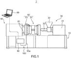
- Fig. 1 is a side view of an overall configuration of an injection molding machine of the embodiment of the present invention.
- Fig. 2 is a sectional view of a configuration of a mold used in the injection molding machine of the embodiment of the present invention.
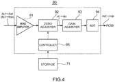
- Fig. 3 is a block diagram of a configuration of a pressure detection device used in the injection molding machine of the embodiment of the present invention.
- Fig. 4 is a block diagram of a configuration of an amplifier of the pressure detection device of the embodiment of the present invention.
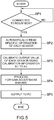
- Fig. 5 is a flow chart of a calibration process for a pressure sensor being performed by the amplifier of the pressure detection device of the embodiment of the present invention.
- an injection molding machine 1 includes a bed 10, an injection unit 30, a mold unit 50, and a mold clamping unit 80, the injection unit 30, mold unit 50, and mold clamping unit 80 being mounted and supported on the bed 10.
- the injection unit 30 includes a driver 31 using a hydraulic motor, a hopper 32, and a cylinder 33.
- the injection unit 30 is a mechanical part configured to heat a material fed through the hopper 32 by the cylinder 33 and inject the material having been heated (hereinafter also referred to as "heated material") to a cavity CT ( Fig. 2 ) of a mold 51 of the mold unit 50 through a nozzle (not shown) at a distal end of the cylinder 33 to fill the cavity CT by driving the cylinder 33 by the driver 31.
- the mold unit 50 which is a mechanical part configured to eject the heated material injected from the cylinder 33 of the injection unit 30 after the heated material is molded in the cavity CT of the mold 51, includes the mold 51 and a relay box 70 (relay device). It should be noted that configurations of the mold 51 and the relay box 70 will be described later.
- the mold clamping unit 80 is a, for example, toggle or direct-pressure mechanical part configured to open and close the mold 51 of the mold unit 50 and to apply a pressure for keeping the mold 51 closed against a pressure of the heated material filling the cavity CT.
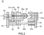
- the mold 51 includes a fixed-side mold 53 attached to a fixed-side attachment plate 52 and a movable-side mold 58 attached to a movable-side attachment plate 54 via a spacer block 55.
- the fixed-side mold 53 is provided with a curved recessed part 53a for defining the cavity CT between the movable-side mold 58 and the fixed-side mold 53, and a guide hole 53b.
- the movable-side mold 58 is provided with a protruding part 58a for defining the cavity CT between the fixed-side mold 53 and the movable-side mold 58, and a guide pin 58b at a position facing the guide hole 53b of the fixed-side mold 53.
- an ejector pin 59 is longitudinally movably supported at a position corresponding to a central portion of the movable-side mold 58 and a center of the cavity CT, penetrating through a center of the protruding part 58a.
- a distal end portion of the ejector pin 59 is a portion that is to abut on a product 65 molded in accordance with a shape of the cavity CT for ejection of the product 65.
- a rear end portion of the ejector pin 59 is integrally attached to an ejector plate 57 and a force sensor S1 (pressure sensor) is integrally attached to an end surface of the rear end portion.
- the mold 51 has a plurality of cavities CT defined between the fixed-side mold 53 and the movable-side mold 58 and force sensors S2 to Sn are integrally fixed to end surfaces of rear end portions of the ejector pins 59 corresponding one-to-one to the cavities CT.
- the force sensors S1 to Sn are provided in one-to-one correspondence with the plurality of cavities CT.
- strain gauges are used as the force sensors S1 to Sn and inner pressures of the cavities CT are applied to the respective force sensors S1 to Sn through the ejector pins 59.
- the force sensors S1 to Sn can thus detect the inner pressures of the respective cavities CT (in this case, fill pressures of the heated material fed by the injection unit 30 to fill the respective cavities CT).
- the ejector plate 57 is attached with an ejector rod 56 at a side facing the movable-side attachment plate 54 and attached with a return pin 60 at a side facing the movable-side mold 58.
- the ejector rod 56 is attached to the ejector plate 57, while penetrating through the movable-side attachment plate 54.
- the return pin 60 is attached with a spring (not shown) for returning the ejector plate 57 to an original position.
- the mold clamping unit 80 ( Fig. 1 ) includes an enclosure, a hydraulic cylinder in the enclosure, and four tie bars 81 connecting four corners of the enclosure to four corners of each of the fixed-side attachment plate 52 and the movable-side attachment plate 54, respectively.
- the ejector rod 56 of the mold 51 is connected to the hydraulic cylinder of the mold clamping unit 80.
- the relay box 70 is removably integrally fixed to the mold 51 of the mold unit 50. Specifically, the relay box 70 is fixed at any place where it does not interfere with a motion of the mold 51.
- the relay box 70 is integrally fixed while being housed in a pocket-shaped recessed part formed on a metal surface of the mold 51.
- the relay box 70 is not necessarily fixed as described above.
- the relay box 70 may be firmly integrally fixed to the metal surface of the mold 51 using a magnet or may be integrally fixed in any other manner.
- a dedicated amplifier 90 is connected to the relay box 70 through a single connection cord 90a and a personal computer 99 is connected to the amplifier 90. It should be noted that the amplifier 90 and the relay box 70 and the amplifier 90 and the personal computer 99 are not necessarily connected by wire but may be wirelessly connected by a method such as near field communication.
- the relay box 70 which is integrally fixed to the mold 51, the amplifier 90 (signal amplifier), and the connection cord 90a provide an inner pressure detection device 100 (pressure detection device). It should be noted that the amplifier 90 is disposed inside the bed 10 in consideration of connectivity of the relay box 70 through the connection cord 90a.
- the relay box 70 in the inner pressure detection device 100 is a functional part configured to relay sensor outputs from the plurality of force sensors S1 to Sn, which are integrally provided to the mold 51 (mold A), to the amplifier 90.
- the relay box 70 which include a box-shaped member, includes a storage 71 (storage A) such as a rewritable non-volatile memory (EEPROM) disposed inside the box-shaped member, while having the above relay function.
- the storage 71 stores individual specific information of each sensor including a difference of an actual output value of each of the plurality of force sensors S1 to Sn, which are disposed in one-to-one correspondence with the plurality of ejector pins 59 of the mold 51, from a rated output thereof.
- the storage 71 (storage A) still stores the actual output value. It should be noted that the specific information of each of the force sensors S1 to Sn to be stored in the storage 71 (storage A) needs to be initially inputted by an operator through the personal computer 99 to be stored in the storage 71 (storage A).
- the relay box 70 which has a size, for example, suitable to be attached to or embedded in the mold 51, includes the storage 71 in the form of a non-volatile memory with a high capacity, thus being capable of storing all the individual specific information of the plurality of force sensors S1 to Sn.
- the specific information stored in the storage 71 includes sensor number, output value, calibration information, rated load, pin-sectional area of the ejector pin 59, serial number, and lot number, for example.
- serial number P1 e.g., [ABC98765]
- lot number Q1 e.g., [180615Q]
- serial number Pn e.g., [XYZ34567]
- lot number Qn e.g., [251015D]
- the like specific information of the force sensor Sn in the mold A is also stored in the storage 71 (storage A). In other words, the specific information of each of the force sensors S1 to Sn in the mold A is stored in the storage 71 (storage A).
- the force sensor S1 in another mold 51 (mold B) prepared as a replacing mold for the injection molding machine 1 has an actual output value Bs1 of 0.62 [mV/V] and the force sensor Sn has an actual output value Bsn of 0.63 [mV/V].
- the serial number P1 e.g., [ABC98765]
- lot number Q1 e.g., [180615Q]
- the serial number Pn e.g., [XYZ34567]
- lot number Qn e.g., [251015D]
- the like specific information of the force sensor Sn in the mold B is also stored in the storage 71. In other words, the specific information of each of the force sensors S1 to Sn in the mold B is stored in the storage 71 (storage B).
- the relay box 70 (relay box A) of the inner pressure detection device 100 is connected to the amplifier 90 through the connection cord 90a, the specific information of each of the force sensors S1 to Sn stored in the storage 71 (storage A) is readable by the amplifier 90.
- the amplifier 90 includes a head amplifier 91, a zero adjuster 92, a gain adjuster 93, an analog/digital converter (ADC) 94, and a controller 95.
- the controller 95 is configured to collectively control the head amplifier 91, the zero adjuster 92, the gain adjuster 93, and the analog/digital converter 94.
- the controller 95 can read the specific information from the storage 71 of the relay box 70.
- the head amplifier 91 is a functional part configured to amplify the actual output values of the force sensors S1 to Sn supplied from the relay box 70.
- the zero adjuster 92 is a functional part configured to adjust the actual output values of the force sensors S1 to Sn using the calibration information K1 to Kn to accurate output values with respect to zero point, respectively.
- the gain adjuster 93 is a functional part configured to amplify the output values of the force sensors S1 to Sn.
- the analog/digital converter 94 is a functional part configured to convert the output value (analog signals) of the force sensors S1 to Sn to digital pressure detection data and output the digital pressure detection data to the personal computer 99.
- the controller 95 which include a microcomputer including a CPU and a memory, is a functional part configured to collectively control each the components of the amplifier 90.
- the controller 95 of the amplifier 90 has a plug- and-play function and thus automatically reads, when recognizing connection to the relay box 70 (relay box A) through the connection cord 90a, the specific information (sensor number Sn, output value As, calibration information K, rated load F, pin-sectional area CS of the ejector pin, serial number P, and lot number Q) of each of the force sensors S1 to Sn from the storage 71 of the relay box 70.
- Step SP1 the controller 95 of the amplifier 90 of the inner pressure detection device 100 determines whether the amplifier 90 is electrically connected to the relay box 70, which is integrally fixed to the mold 51 through the connection cord 90a (Step SP1).
- Step SP1 the controller 95 recognizes that the inner pressures of the cavities CT of the mold 51 are undetectable and waits for the result of determination to become positive.
- Step SP1 the controller 95 recognizes that the amplifier 90 is electrically connected to the relay box 70 with the inner pressures of the cavities CT of the mold 51 being detectable.
- the inner pressures of the cavities CT are applied to the respective force sensors S1 to Sn attached to the rear end surfaces of the ejector pins 59.
- the actual output values As1 to Asn from the respective force sensors S1 to Sn are thus obtained as detection results and the plurality of actual output values As1 to Asn are sent to the relay box 70 (relay box A).
- Step SP2 While sending the output values As1 to Asn, which is relayed from the relay box 70, to the zero adjuster 92 via the head amplifier 91, the controller 95 of the amplifier 90 reads the specific information of each of the force sensors S1 to Sn from the storage 71 of the relay box 70 and outputs the specific information to the zero adjuster 92 (Step SP2).
- the controller 95 of the amplifier 90 calibrates the actual output values As1 to Asn of the force sensors S1 to Sn using the calibration information K1 to Kn among the specific information of the force sensors S1 to Sn read from the storage 71 of the relay box 70 by the zero adjuster 92, thus generating calibrated accurate correction output values H1 to Hn (Step SP3).
- the controller 95 of the amplifier 90 commands the gain adjuster 93 to amplify the accurate correction output values H1 to Hn calibrated by the zero adjuster 92 and, subsequently, commands the analog/digital converter 94 to convert the accurate correction output values H1 to Hn to digital correction output data Hd1 to Hdn (Step SP4).
- the controller 95 of the amplifier 90 then outputs the correction output data Hd1 to Hdn to the personal computer 99 and displays accurate inner pressure values corresponding to the correction output data Hd1 to Hdn on a monitor of the personal computer 99 so that an operator can see the inner pressure values (Step SP5).
- the above series of process is also performed when the mold A is replaced with the mold B.
- the controller 95 of the amplifier 90 reads the specific information of each of the force sensors S1 to Sn in the mold B, which is stored in advance in the storage 71 of the relay box 70 (relay box B) integrally fixed to the mold B, so that the actual output values Bs1 to Bsn can be calibrated to output the accurate correction output data Hd1 to Hdn.
- the inner pressure detection device 100 eliminates the necessity of storing in advance the specific information of each of the force sensors S1 to Sn in each of the plurality of molds 51 in the amplifier 90 and the personal computer 99 and allows the amplifier 90 to read the specific information of each of the force sensors S1 to Sn merely by connecting the amplifier 90 to the relay box 70 integrally fixed to the mold 51.
- the inner pressure detection device 100 can thus output accurate detection results without making an operator particularly aware of calibration even when there are differences between the actual output values of the force sensors S1 to Sn.
- the controller 95 of the inner pressure detection device 100 can read the pin-sectional area CS of each of the ejector pins 59 from the storage 71 of the relay box 70, so that the actual pressure value of each of the force sensors S1 to Sn can be obtained based on a load value (the inner pressure of the corresponding cavity CT) detected by corresponding one of the force sensors S1 to Sn, which are indicated by the correction output data Hd1 to Hdn, and the pin-sectional area CS.
- the controller 95 can thus determine whether the actual pressure value is an abnormal value exceeding a maximum load represented by the rated load F. When the actual pressure value is determined to be the abnormal value, the controller 95 can report the determination result to the personal computer 99 so that the determination result is displayed on the monitor, urging an operator to stop the operation of the injection molding machine 1.
- the controller 95 of the amplifier 90 can read the serial number P and the lot number Q of each of the force sensors S1 to Sn stored in advance in the storage 71 of the relay box 70 and output the serial number P and the lot number Q to the monitor of the personal computer 99.
- An operator can thus see the serial number P of each of the force sensors S1 to Sn, thereby identifying the manufacturing date of each of the force sensors S1 to Sn provided to the mold 51 and, consequently, determining the necessity of replacement of each of the force sensors S1 to Sn.
- the operator can also see the lot number Q of each of the force sensors S1 to Sn, thereby determining the necessity and time of replacement of each of the force sensors S1 to Sn in view of the possibility of being defective and the risk level of malfunction based on the defective rate of sensors with the lot number Q.
- the inner pressure detection device 100 is configured to require an operator to first input the specific information of each of the force sensors S1 to Sn through the personal computer 99 so that the specific information is stored in the storage 71.
- Such a configuration of the inner pressure detection device 100 allows for updating, when the force sensors S1 to Sn provided to the mold 51 are replaced with new ones, the specific information of the force sensors S1 to Sn by inputting the specific information of each of the replacing new force sensors S1 to Sn.
- the storage 71 can always store the latest specific information of each of the force sensors S1 to Sn in the mold 51 for the use in calibration and the like.
- the relay box 70 is removably integrally fixed to the mold 51 but the present invention is not limited thereto.
- the relay box 70 may be non-removably integrally fixed to the mold 51 with the storage 71 being removably integrally fixed to the relay box 70.
- the present invention is not limited thereto.
- the personal computer 99 may include the functional parts of the amplifier 90.
- the inner pressure detection device 100 includes the relay box 70 and the personal computer 99.
- the present invention is not limited to the inner pressure detection device 100 of the above embodiment but may be implemented in any embodiments within the concept of the present invention and scope of the claims.
- the components may be selectively combined as needed to achieve at least a part of the above object and effects.
- the shape, material, location, size, and the like of each component of the above embodiment may be changed as needed in accordance with a specific implementation of the present invention.
Landscapes
- Engineering & Computer Science (AREA)
- Mechanical Engineering (AREA)
- Manufacturing & Machinery (AREA)
- Physics & Mathematics (AREA)
- General Physics & Mathematics (AREA)
- Chemical & Material Sciences (AREA)
- Analytical Chemistry (AREA)
- Injection Moulding Of Plastics Or The Like (AREA)
- Measuring Fluid Pressure (AREA)
- Moulds For Moulding Plastics Or The Like (AREA)
Applications Claiming Priority (2)
| Application Number | Priority Date | Filing Date | Title |
|---|---|---|---|
| JP2016238554A JP6389502B2 (ja) | 2016-12-08 | 2016-12-08 | 中継装置および圧力検出装置 |
| PCT/JP2017/036590 WO2018105227A1 (fr) | 2016-12-08 | 2017-10-10 | Dispositif de relais et dispositif de détection de pression |
Publications (3)
| Publication Number | Publication Date |
|---|---|
| EP3552797A1 true EP3552797A1 (fr) | 2019-10-16 |
| EP3552797A4 EP3552797A4 (fr) | 2020-01-22 |
| EP3552797B1 EP3552797B1 (fr) | 2021-01-27 |
Family
ID=62492166
Family Applications (1)
| Application Number | Title | Priority Date | Filing Date |
|---|---|---|---|
| EP17878370.0A Active EP3552797B1 (fr) | 2016-12-08 | 2017-10-10 | Dispositif de relais et dispositif de détection de pression |
Country Status (6)
| Country | Link |
|---|---|
| US (1) | US10646918B2 (fr) |
| EP (1) | EP3552797B1 (fr) |
| JP (1) | JP6389502B2 (fr) |
| KR (1) | KR102206406B1 (fr) |
| CN (1) | CN110049855A (fr) |
| WO (1) | WO2018105227A1 (fr) |
Families Citing this family (4)
| Publication number | Priority date | Publication date | Assignee | Title |
|---|---|---|---|---|
| JP6389502B2 (ja) | 2016-12-08 | 2018-09-12 | ミネベアミツミ株式会社 | 中継装置および圧力検出装置 |
| JP7349869B2 (ja) * | 2019-10-02 | 2023-09-25 | ミネベアミツミ株式会社 | 圧力検出装置および良否判断方法 |
| JP7349868B2 (ja) * | 2019-10-02 | 2023-09-25 | ミネベアミツミ株式会社 | 圧力検出装置および良否判断方法 |
| CN114012062A (zh) * | 2021-10-15 | 2022-02-08 | 东风汽车集团股份有限公司 | 一种动模 |
Family Cites Families (18)
| Publication number | Priority date | Publication date | Assignee | Title |
|---|---|---|---|---|
| US3807914A (en) | 1972-12-04 | 1974-04-30 | Control Process Inc | Cavity pressure control system |
| DE3440378A1 (de) * | 1984-11-05 | 1986-05-22 | Voest-Alpine Friedmann GmbH, Linz | Kompensierbarer druck-messwertgeber |
| JPH0591823U (ja) * | 1992-05-22 | 1993-12-14 | エヌオーケー株式会社 | 射出成形用金型 |
| JP2527110B2 (ja) * | 1992-06-30 | 1996-08-21 | 日精樹脂工業株式会社 | 射出成形機の金型交換方法及び装置 |
| JP2929349B2 (ja) | 1993-09-08 | 1999-08-03 | 日精樹脂工業株式会社 | 射出成形機の圧力検出方法及び装置 |
| JPH09159559A (ja) * | 1995-12-04 | 1997-06-20 | Matsushita Electric Ind Co Ltd | 不揮発性メモリ搭載型圧力センサ |
| JP3937525B2 (ja) * | 1997-09-10 | 2007-06-27 | 双葉電子工業株式会社 | 圧力センサ付エジェクタピン |
| KR200317981Y1 (ko) | 2003-03-26 | 2003-06-27 | 유영산업 | 사출금형의 성형부압력측정구조 |
| JP2006196598A (ja) * | 2005-01-12 | 2006-07-27 | Sharp Corp | ソリッドステートリレー、電子機器及びソリッドステートリレーの製造方法 |
| JP4861774B2 (ja) * | 2006-08-30 | 2012-01-25 | 住友重機械工業株式会社 | 射出成形機及び射出成形機の制御方法 |
| JP4717020B2 (ja) * | 2007-01-31 | 2011-07-06 | 富士通株式会社 | 中継基板および光通信モジュール |
| US8378766B2 (en) * | 2011-02-03 | 2013-02-19 | National Semiconductor Corporation | MEMS relay and method of forming the MEMS relay |
| JP5859387B2 (ja) | 2012-06-20 | 2016-02-10 | カルソニックカンセイ株式会社 | 樹脂成形装置および樹脂成形方法 |
| JP2014122858A (ja) * | 2012-12-21 | 2014-07-03 | Toyota Motor Corp | 圧力検出方法 |
| CN103481478B (zh) | 2013-10-08 | 2015-11-18 | 广州创维平面显示科技有限公司 | 注塑模具 |
| CN205395008U (zh) | 2016-03-09 | 2016-07-27 | 黄河科技学院 | 可安全自动化脱模的注塑模具 |
| JP6656125B2 (ja) * | 2016-09-09 | 2020-03-04 | 株式会社鷺宮製作所 | 圧力センサ、その中継基板、及び、その中継基板ユニット |
| JP6389502B2 (ja) | 2016-12-08 | 2018-09-12 | ミネベアミツミ株式会社 | 中継装置および圧力検出装置 |
-
2016
- 2016-12-08 JP JP2016238554A patent/JP6389502B2/ja active Active
-
2017
- 2017-10-10 WO PCT/JP2017/036590 patent/WO2018105227A1/fr unknown
- 2017-10-10 KR KR1020197017576A patent/KR102206406B1/ko active IP Right Grant
- 2017-10-10 EP EP17878370.0A patent/EP3552797B1/fr active Active
- 2017-10-10 US US16/467,203 patent/US10646918B2/en active Active
- 2017-10-10 CN CN201780076143.2A patent/CN110049855A/zh active Pending
Also Published As
| Publication number | Publication date |
|---|---|
| KR102206406B1 (ko) | 2021-01-22 |
| EP3552797A4 (fr) | 2020-01-22 |
| JP2018094729A (ja) | 2018-06-21 |
| JP6389502B2 (ja) | 2018-09-12 |
| KR20190088495A (ko) | 2019-07-26 |
| WO2018105227A1 (fr) | 2018-06-14 |
| CN110049855A (zh) | 2019-07-23 |
| US10646918B2 (en) | 2020-05-12 |
| US20190314890A1 (en) | 2019-10-17 |
| EP3552797B1 (fr) | 2021-01-27 |
Similar Documents
| Publication | Publication Date | Title |
|---|---|---|
| EP3552797B1 (fr) | Dispositif de relais et dispositif de détection de pression | |
| CN108115911B (zh) | 注射成形机的控制装置以及管理系统 | |
| US7275922B2 (en) | Controller for an ejector mechanism in an injection molding machine | |
| US20200086542A1 (en) | Methods for controlling injection molding processes based on actual plastic melt pressure or cavity pressure | |
| CN105500656B (zh) | 具备多个注射装置的注射成形机 | |
| CN112643981A (zh) | 注塑成型信息管理辅助装置及注塑成型机 | |
| US20170080621A1 (en) | Injection molding method of resin molded article and specifying method of clamping force | |
| CN207657127U (zh) | 一种用于模具型腔内的测压装置及注塑模具 | |
| US20170274572A1 (en) | Abnormality detection device for injection molding machine | |
| US9701054B2 (en) | Injection molding system | |
| EP4039442A1 (fr) | Dispositif de détection de pression et procédé de détermination de qualité | |
| EP3552796B1 (fr) | Appareil de moulage par injection et procédé de moulage par injection | |
| EP4039441A1 (fr) | Dispositif de détection de pression et procédé de détermination de qualité | |
| CN216941724U (zh) | 一种基于注塑机的针阀控制系统 | |
| JPS61283518A (ja) | 射出成形機の型締力補正装置 | |
| CN103619559B (zh) | 注塑成型机 | |
| CN108127865A (zh) | 模具堆叠 | |
| US20060110489A1 (en) | Apparatus for measuring separation of mold parts | |
| US20240140010A1 (en) | Information processing device, injection molding machine, and non-transitory computer readable medium storing program | |
| JP2021091094A (ja) | 樹脂成形装置および樹脂成形品の製造方法 | |
| JPS6356409A (ja) | 型装置 | |
| JP6426511B2 (ja) | 射出成形機の負荷検出装置 | |
| JP2020029055A (ja) | 射出成形機 |
Legal Events
| Date | Code | Title | Description |
|---|---|---|---|
| STAA | Information on the status of an ep patent application or granted ep patent |
Free format text: STATUS: THE INTERNATIONAL PUBLICATION HAS BEEN MADE |
|
| PUAI | Public reference made under article 153(3) epc to a published international application that has entered the european phase |
Free format text: ORIGINAL CODE: 0009012 |
|
| STAA | Information on the status of an ep patent application or granted ep patent |
Free format text: STATUS: REQUEST FOR EXAMINATION WAS MADE |
|
| 17P | Request for examination filed |
Effective date: 20190703 |
|
| AK | Designated contracting states |
Kind code of ref document: A1 Designated state(s): AL AT BE BG CH CY CZ DE DK EE ES FI FR GB GR HR HU IE IS IT LI LT LU LV MC MK MT NL NO PL PT RO RS SE SI SK SM TR |
|
| AX | Request for extension of the european patent |
Extension state: BA ME |
|
| A4 | Supplementary search report drawn up and despatched |
Effective date: 20200102 |
|
| RIC1 | Information provided on ipc code assigned before grant |
Ipc: B29C 45/77 20060101AFI20191217BHEP Ipc: B22D 17/32 20060101ALI20191217BHEP Ipc: B29C 45/26 20060101ALI20191217BHEP Ipc: G01L 27/00 20060101ALI20191217BHEP |
|
| DAV | Request for validation of the european patent (deleted) | ||
| DAX | Request for extension of the european patent (deleted) | ||
| GRAP | Despatch of communication of intention to grant a patent |
Free format text: ORIGINAL CODE: EPIDOSNIGR1 |
|
| STAA | Information on the status of an ep patent application or granted ep patent |
Free format text: STATUS: GRANT OF PATENT IS INTENDED |
|
| RIC1 | Information provided on ipc code assigned before grant |
Ipc: B29C 45/77 20060101AFI20200728BHEP Ipc: B22D 18/02 20060101ALI20200728BHEP Ipc: G01L 27/00 20060101ALI20200728BHEP Ipc: B29C 45/26 20060101ALI20200728BHEP Ipc: B22D 17/32 20060101ALI20200728BHEP Ipc: G01L 7/00 20060101ALI20200728BHEP |
|
| INTG | Intention to grant announced |
Effective date: 20200826 |
|
| GRAS | Grant fee paid |
Free format text: ORIGINAL CODE: EPIDOSNIGR3 |
|
| GRAA | (expected) grant |
Free format text: ORIGINAL CODE: 0009210 |
|
| STAA | Information on the status of an ep patent application or granted ep patent |
Free format text: STATUS: THE PATENT HAS BEEN GRANTED |
|
| AK | Designated contracting states |
Kind code of ref document: B1 Designated state(s): AL AT BE BG CH CY CZ DE DK EE ES FI FR GB GR HR HU IE IS IT LI LT LU LV MC MK MT NL NO PL PT RO RS SE SI SK SM TR |
|
| REG | Reference to a national code |
Ref country code: GB Ref legal event code: FG4D |
|
| REG | Reference to a national code |
Ref country code: CH Ref legal event code: EP |
|
| REG | Reference to a national code |
Ref country code: AT Ref legal event code: REF Ref document number: 1357948 Country of ref document: AT Kind code of ref document: T Effective date: 20210215 |
|
| REG | Reference to a national code |
Ref country code: IE Ref legal event code: FG4D |
|
| REG | Reference to a national code |
Ref country code: DE Ref legal event code: R096 Ref document number: 602017032295 Country of ref document: DE |
|
| REG | Reference to a national code |
Ref country code: NL Ref legal event code: MP Effective date: 20210127 |
|
| REG | Reference to a national code |
Ref country code: LT Ref legal event code: MG9D |
|
| REG | Reference to a national code |
Ref country code: AT Ref legal event code: MK05 Ref document number: 1357948 Country of ref document: AT Kind code of ref document: T Effective date: 20210127 |
|
| PG25 | Lapsed in a contracting state [announced via postgrant information from national office to epo] |
Ref country code: LT Free format text: LAPSE BECAUSE OF FAILURE TO SUBMIT A TRANSLATION OF THE DESCRIPTION OR TO PAY THE FEE WITHIN THE PRESCRIBED TIME-LIMIT Effective date: 20210127 Ref country code: BG Free format text: LAPSE BECAUSE OF FAILURE TO SUBMIT A TRANSLATION OF THE DESCRIPTION OR TO PAY THE FEE WITHIN THE PRESCRIBED TIME-LIMIT Effective date: 20210427 Ref country code: PT Free format text: LAPSE BECAUSE OF FAILURE TO SUBMIT A TRANSLATION OF THE DESCRIPTION OR TO PAY THE FEE WITHIN THE PRESCRIBED TIME-LIMIT Effective date: 20210527 Ref country code: NO Free format text: LAPSE BECAUSE OF FAILURE TO SUBMIT A TRANSLATION OF THE DESCRIPTION OR TO PAY THE FEE WITHIN THE PRESCRIBED TIME-LIMIT Effective date: 20210427 Ref country code: FI Free format text: LAPSE BECAUSE OF FAILURE TO SUBMIT A TRANSLATION OF THE DESCRIPTION OR TO PAY THE FEE WITHIN THE PRESCRIBED TIME-LIMIT Effective date: 20210127 Ref country code: GR Free format text: LAPSE BECAUSE OF FAILURE TO SUBMIT A TRANSLATION OF THE DESCRIPTION OR TO PAY THE FEE WITHIN THE PRESCRIBED TIME-LIMIT Effective date: 20210428 Ref country code: HR Free format text: LAPSE BECAUSE OF FAILURE TO SUBMIT A TRANSLATION OF THE DESCRIPTION OR TO PAY THE FEE WITHIN THE PRESCRIBED TIME-LIMIT Effective date: 20210127 |
|
| PG25 | Lapsed in a contracting state [announced via postgrant information from national office to epo] |
Ref country code: AT Free format text: LAPSE BECAUSE OF FAILURE TO SUBMIT A TRANSLATION OF THE DESCRIPTION OR TO PAY THE FEE WITHIN THE PRESCRIBED TIME-LIMIT Effective date: 20210127 Ref country code: RS Free format text: LAPSE BECAUSE OF FAILURE TO SUBMIT A TRANSLATION OF THE DESCRIPTION OR TO PAY THE FEE WITHIN THE PRESCRIBED TIME-LIMIT Effective date: 20210127 Ref country code: PL Free format text: LAPSE BECAUSE OF FAILURE TO SUBMIT A TRANSLATION OF THE DESCRIPTION OR TO PAY THE FEE WITHIN THE PRESCRIBED TIME-LIMIT Effective date: 20210127 Ref country code: LV Free format text: LAPSE BECAUSE OF FAILURE TO SUBMIT A TRANSLATION OF THE DESCRIPTION OR TO PAY THE FEE WITHIN THE PRESCRIBED TIME-LIMIT Effective date: 20210127 Ref country code: SE Free format text: LAPSE BECAUSE OF FAILURE TO SUBMIT A TRANSLATION OF THE DESCRIPTION OR TO PAY THE FEE WITHIN THE PRESCRIBED TIME-LIMIT Effective date: 20210127 |
|
| PG25 | Lapsed in a contracting state [announced via postgrant information from national office to epo] |
Ref country code: IS Free format text: LAPSE BECAUSE OF FAILURE TO SUBMIT A TRANSLATION OF THE DESCRIPTION OR TO PAY THE FEE WITHIN THE PRESCRIBED TIME-LIMIT Effective date: 20210527 |
|
| REG | Reference to a national code |
Ref country code: DE Ref legal event code: R097 Ref document number: 602017032295 Country of ref document: DE |
|
| PG25 | Lapsed in a contracting state [announced via postgrant information from national office to epo] |
Ref country code: SM Free format text: LAPSE BECAUSE OF FAILURE TO SUBMIT A TRANSLATION OF THE DESCRIPTION OR TO PAY THE FEE WITHIN THE PRESCRIBED TIME-LIMIT Effective date: 20210127 Ref country code: CZ Free format text: LAPSE BECAUSE OF FAILURE TO SUBMIT A TRANSLATION OF THE DESCRIPTION OR TO PAY THE FEE WITHIN THE PRESCRIBED TIME-LIMIT Effective date: 20210127 Ref country code: EE Free format text: LAPSE BECAUSE OF FAILURE TO SUBMIT A TRANSLATION OF THE DESCRIPTION OR TO PAY THE FEE WITHIN THE PRESCRIBED TIME-LIMIT Effective date: 20210127 |
|
| PG25 | Lapsed in a contracting state [announced via postgrant information from national office to epo] |
Ref country code: SK Free format text: LAPSE BECAUSE OF FAILURE TO SUBMIT A TRANSLATION OF THE DESCRIPTION OR TO PAY THE FEE WITHIN THE PRESCRIBED TIME-LIMIT Effective date: 20210127 Ref country code: DK Free format text: LAPSE BECAUSE OF FAILURE TO SUBMIT A TRANSLATION OF THE DESCRIPTION OR TO PAY THE FEE WITHIN THE PRESCRIBED TIME-LIMIT Effective date: 20210127 Ref country code: RO Free format text: LAPSE BECAUSE OF FAILURE TO SUBMIT A TRANSLATION OF THE DESCRIPTION OR TO PAY THE FEE WITHIN THE PRESCRIBED TIME-LIMIT Effective date: 20210127 |
|
| PLBE | No opposition filed within time limit |
Free format text: ORIGINAL CODE: 0009261 |
|
| STAA | Information on the status of an ep patent application or granted ep patent |
Free format text: STATUS: NO OPPOSITION FILED WITHIN TIME LIMIT |
|
| 26N | No opposition filed |
Effective date: 20211028 |
|
| PG25 | Lapsed in a contracting state [announced via postgrant information from national office to epo] |
Ref country code: ES Free format text: LAPSE BECAUSE OF FAILURE TO SUBMIT A TRANSLATION OF THE DESCRIPTION OR TO PAY THE FEE WITHIN THE PRESCRIBED TIME-LIMIT Effective date: 20210127 Ref country code: AL Free format text: LAPSE BECAUSE OF FAILURE TO SUBMIT A TRANSLATION OF THE DESCRIPTION OR TO PAY THE FEE WITHIN THE PRESCRIBED TIME-LIMIT Effective date: 20210127 |
|
| PG25 | Lapsed in a contracting state [announced via postgrant information from national office to epo] |
Ref country code: SI Free format text: LAPSE BECAUSE OF FAILURE TO SUBMIT A TRANSLATION OF THE DESCRIPTION OR TO PAY THE FEE WITHIN THE PRESCRIBED TIME-LIMIT Effective date: 20210127 |
|
| PG25 | Lapsed in a contracting state [announced via postgrant information from national office to epo] |
Ref country code: IT Free format text: LAPSE BECAUSE OF FAILURE TO SUBMIT A TRANSLATION OF THE DESCRIPTION OR TO PAY THE FEE WITHIN THE PRESCRIBED TIME-LIMIT Effective date: 20210127 |
|
| REG | Reference to a national code |
Ref country code: CH Ref legal event code: PL |
|
| PG25 | Lapsed in a contracting state [announced via postgrant information from national office to epo] |
Ref country code: IS Free format text: LAPSE BECAUSE OF FAILURE TO SUBMIT A TRANSLATION OF THE DESCRIPTION OR TO PAY THE FEE WITHIN THE PRESCRIBED TIME-LIMIT Effective date: 20210527 |
|
| REG | Reference to a national code |
Ref country code: BE Ref legal event code: MM Effective date: 20211031 |
|
| GBPC | Gb: european patent ceased through non-payment of renewal fee |
Effective date: 20211010 |
|
| PG25 | Lapsed in a contracting state [announced via postgrant information from national office to epo] |
Ref country code: MC Free format text: LAPSE BECAUSE OF FAILURE TO SUBMIT A TRANSLATION OF THE DESCRIPTION OR TO PAY THE FEE WITHIN THE PRESCRIBED TIME-LIMIT Effective date: 20210127 |
|
| PG25 | Lapsed in a contracting state [announced via postgrant information from national office to epo] |
Ref country code: LU Free format text: LAPSE BECAUSE OF NON-PAYMENT OF DUE FEES Effective date: 20211010 Ref country code: GB Free format text: LAPSE BECAUSE OF NON-PAYMENT OF DUE FEES Effective date: 20211010 Ref country code: BE Free format text: LAPSE BECAUSE OF NON-PAYMENT OF DUE FEES Effective date: 20211031 |
|
| PG25 | Lapsed in a contracting state [announced via postgrant information from national office to epo] |
Ref country code: LI Free format text: LAPSE BECAUSE OF NON-PAYMENT OF DUE FEES Effective date: 20211031 Ref country code: CH Free format text: LAPSE BECAUSE OF NON-PAYMENT OF DUE FEES Effective date: 20211031 |
|
| PG25 | Lapsed in a contracting state [announced via postgrant information from national office to epo] |
Ref country code: IE Free format text: LAPSE BECAUSE OF NON-PAYMENT OF DUE FEES Effective date: 20211010 |
|
| PG25 | Lapsed in a contracting state [announced via postgrant information from national office to epo] |
Ref country code: NL Free format text: LAPSE BECAUSE OF NON-PAYMENT OF DUE FEES Effective date: 20210127 Ref country code: CY Free format text: LAPSE BECAUSE OF FAILURE TO SUBMIT A TRANSLATION OF THE DESCRIPTION OR TO PAY THE FEE WITHIN THE PRESCRIBED TIME-LIMIT Effective date: 20210127 |
|
| PG25 | Lapsed in a contracting state [announced via postgrant information from national office to epo] |
Ref country code: HU Free format text: LAPSE BECAUSE OF FAILURE TO SUBMIT A TRANSLATION OF THE DESCRIPTION OR TO PAY THE FEE WITHIN THE PRESCRIBED TIME-LIMIT; INVALID AB INITIO Effective date: 20171010 |
|
| PGFP | Annual fee paid to national office [announced via postgrant information from national office to epo] |
Ref country code: FR Payment date: 20231026 Year of fee payment: 7 Ref country code: DE Payment date: 20231020 Year of fee payment: 7 |
|
| PG25 | Lapsed in a contracting state [announced via postgrant information from national office to epo] |
Ref country code: MK Free format text: LAPSE BECAUSE OF FAILURE TO SUBMIT A TRANSLATION OF THE DESCRIPTION OR TO PAY THE FEE WITHIN THE PRESCRIBED TIME-LIMIT Effective date: 20210127 |