EP3552789B1 - Verfahren zum heizen eines werkstücks aus harz - Google Patents
Verfahren zum heizen eines werkstücks aus harz Download PDFInfo
- Publication number
- EP3552789B1 EP3552789B1 EP18214633.2A EP18214633A EP3552789B1 EP 3552789 B1 EP3552789 B1 EP 3552789B1 EP 18214633 A EP18214633 A EP 18214633A EP 3552789 B1 EP3552789 B1 EP 3552789B1
- Authority
- EP
- European Patent Office
- Prior art keywords
- superheated steam
- workpiece
- resin workpiece
- resin
- nozzles
- Prior art date
- Legal status (The legal status is an assumption and is not a legal conclusion. Google has not performed a legal analysis and makes no representation as to the accuracy of the status listed.)
- Active
Links
Images



Classifications
-
- B—PERFORMING OPERATIONS; TRANSPORTING
- B29—WORKING OF PLASTICS; WORKING OF SUBSTANCES IN A PLASTIC STATE IN GENERAL
- B29B—PREPARATION OR PRETREATMENT OF THE MATERIAL TO BE SHAPED; MAKING GRANULES OR PREFORMS; RECOVERY OF PLASTICS OR OTHER CONSTITUENTS OF WASTE MATERIAL CONTAINING PLASTICS
- B29B13/00—Conditioning or physical treatment of the material to be shaped
- B29B13/02—Conditioning or physical treatment of the material to be shaped by heating
-
- B—PERFORMING OPERATIONS; TRANSPORTING
- B29—WORKING OF PLASTICS; WORKING OF SUBSTANCES IN A PLASTIC STATE IN GENERAL
- B29C—SHAPING OR JOINING OF PLASTICS; SHAPING OF MATERIAL IN A PLASTIC STATE, NOT OTHERWISE PROVIDED FOR; AFTER-TREATMENT OF THE SHAPED PRODUCTS, e.g. REPAIRING
- B29C35/00—Heating, cooling or curing, e.g. crosslinking or vulcanising; Apparatus therefor
- B29C35/02—Heating or curing, e.g. crosslinking or vulcanizing during moulding, e.g. in a mould
- B29C35/04—Heating or curing, e.g. crosslinking or vulcanizing during moulding, e.g. in a mould using liquids, gas or steam
- B29C35/049—Heating or curing, e.g. crosslinking or vulcanizing during moulding, e.g. in a mould using liquids, gas or steam using steam or damp
-
- F—MECHANICAL ENGINEERING; LIGHTING; HEATING; WEAPONS; BLASTING
- F26—DRYING
- F26B—DRYING SOLID MATERIALS OR OBJECTS BY REMOVING LIQUID THEREFROM
- F26B3/00—Drying solid materials or objects by processes involving the application of heat
- F26B3/02—Drying solid materials or objects by processes involving the application of heat by convection, i.e. heat being conveyed from a heat source to the materials or objects to be dried by a gas or vapour, e.g. air
- F26B3/04—Drying solid materials or objects by processes involving the application of heat by convection, i.e. heat being conveyed from a heat source to the materials or objects to be dried by a gas or vapour, e.g. air the gas or vapour circulating over or surrounding the materials or objects to be dried
-
- B—PERFORMING OPERATIONS; TRANSPORTING
- B29—WORKING OF PLASTICS; WORKING OF SUBSTANCES IN A PLASTIC STATE IN GENERAL
- B29B—PREPARATION OR PRETREATMENT OF THE MATERIAL TO BE SHAPED; MAKING GRANULES OR PREFORMS; RECOVERY OF PLASTICS OR OTHER CONSTITUENTS OF WASTE MATERIAL CONTAINING PLASTICS
- B29B13/00—Conditioning or physical treatment of the material to be shaped
- B29B13/02—Conditioning or physical treatment of the material to be shaped by heating
- B29B13/023—Half-products, e.g. films, plates
- B29B2013/026—Obtaining a uniform temperature over the whole surface of films or tubes
-
- B—PERFORMING OPERATIONS; TRANSPORTING
- B29—WORKING OF PLASTICS; WORKING OF SUBSTANCES IN A PLASTIC STATE IN GENERAL
- B29C—SHAPING OR JOINING OF PLASTICS; SHAPING OF MATERIAL IN A PLASTIC STATE, NOT OTHERWISE PROVIDED FOR; AFTER-TREATMENT OF THE SHAPED PRODUCTS, e.g. REPAIRING
- B29C51/00—Shaping by thermoforming, i.e. shaping sheets or sheet like preforms after heating, e.g. shaping sheets in matched moulds or by deep-drawing; Apparatus therefor
- B29C51/26—Component parts, details or accessories; Auxiliary operations
- B29C51/42—Heating or cooling
- B29C51/421—Heating or cooling of preforms, specially adapted for thermoforming
- B29C51/424—Heating or cooling of preforms, specially adapted for thermoforming using a heated fluid
Definitions
- the present disclosure relates to a method for heating a resin workpiece.
- a heating apparatus that supplies superheated steam to a metal workpiece and heats the metal workpiece is known.
- An example of such a heating apparatus has been disclosed in Japanese Unexamined Patent Application Publication No. 2016-075466 .
- a method for manufacturing products including a process of heating a metal workpiece using such a heat apparatus is known.
- WO 2006/093112A1 discloses a thermoforming method wherein superheated steam is brought into contact with a planar workpiece to heat the workpiece via nozzles.
- GB 1 521 037 A discloses a heating process including jetting hot gas and/or steam from nozzle means directly, onto both sides of a continuous sheet.
- the inventors of the present invention have found the following problems.
- the above-described heating apparatus uses a nozzle to blow superheated steam on a metal workpiece so that the superheated steam is supplied to the metal workpiece.
- a surface of the metal workpiece on which the superheated steam is blown and an axis of the nozzle intersect roughly perpendicular to each other.
- One of the reasons for blowing superheated steam by using a nozzle is that since superheated steam comes into contact with a predetermined part of the metal workpiece and the superheated steam transfers heat to the part, the heat is quickly conducted from the part to other parts and the metal workpiece therefore can be heated uniformly.
- the above-described heating apparatus may be used when a resin workpiece having a planar part is heated.
- the heat cannot be conducted quickly in contrast to the above-described case of heating the metal workpiece. Therefore, the temperature of each part of the resin workpiece tends to be nonuniform.
- the present invention enables a resin workpiece to be heated uniformly.
- a first exemplary aspect of the invention which is defined by the subject-matter of claim 1, is a method for heating a resin workpiece, including a heating process for supplying superheated steam from a plurality of nozzles to heat a resin workpiece having a planar part, and in the heating process, the superheated steam is blown on the resin workpiece from the plurality of nozzles to heat the resin workpiece in a state that each axis of the plurality of nozzles is arranged so as to be inclined in one direction along the plane of a planar part with respect to a normal of the planar part.
- the superheated steam blown from the plurality of nozzles uniformly flows along the plane of the planar part of the resin workpiece. Therefore, the superheated steam quickly transmits heat to the planar part of the resin workpiece. Further, to enable a successive supply of new superheated steam, the superheated steam which has transmitted heat is quickly discharged from the planar part of the resin workpiece. Accordingly, the resin workpiece can be heated uniformly. Further, since a need to add additional nozzles decreases, the cost can be prevented from increasing due to such addition.
- the resin workpiece is a planar body having one main surface and the other main surface
- the plurality of nozzles include a plurality of first nozzles (for example, a nozzle 3a) and a plurality of second nozzles (for example, a nozzle 4a),
- the superheated steam is blown on the both surfaces of the resin workpiece from the respective first and the second nozzles in directions opposite to each other, and thereby flows on each of the both surfaces of the resin workpiece in directions opposite to each other. Therefore, the superheated steam circulates on each of the both surfaces of the resin workpiece. Further, the superheated steam conducts heat to the both surfaces of the resin workpiece. Accordingly, the resin workpiece can be further heated uniformly. Further, the cost can be further prevented from increasing due to the addition of the nozzle.
- the method for heating a resin workpiece further includes using discharge means for discharging the superheated steam (for example, exhaust ports 53 and 54), and the discharge means are provided on the downstream side of the superheated steam with respect to the resin workpiece.
- the superheated steam which has flowed along the resin workpiece is discharged by the discharge means. Therefore, new superheated steam can be blown successively on the resin workpiece.
- new superheated steam successively flows along the resin workpiece so that the superheated steam can provide heat to the resin workpiece. Accordingly, the resin workpiece can be heated quickly.
- the method for manufacturing a resin member further includes using shielding members, and the shielding members are provided on the both ends of the resin workpiece to shield the superheated steam.
- the shielding members shield superheated steam so that the discharge means can discharge the superheated steam more easily.
- new superheated steam successively flows along the resin workpiece so that the superheated steam can provide heat thereto. Accordingly, the resin workpiece can be further heated quickly.
- the present invention enables the resin workpiece to be heated uniformly.
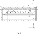
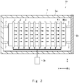
- a workpiece heating apparatus 10 includes a housing 1, a frame 2, and nozzles 3a.
- the housing 1 includes a housing body 1a having an internal space capable of accommodating a resin workpiece W1 and a door 1b capable of being opened and closed.
- the frame 2 and the nozzles 3a are provided in the internal space of the housing body 1a.
- the housing 1 has a substantially rectangular parallelepiped shape.
- the shape of the housing 1 is not limited to that of this example and the housing body 1 has various shapes.
- the resin workpiece W1 includes a resin material or a fiber-reinforced composite material.
- the resin material include polyethylene, polypropylene, polyurethane, polyamide (nylon), and the like.
- the fiber-reinforced composite material include glass fiber-reinforced plastic (GFRP), carbon fiber-reinforced plastic (CFRP), and the like.
- the resin workpiece W1 may have any shape provided with a planar part having a plane of a predetermined size. Examples of such shapes include a plate shape or a shape having a plate part and a thick part mechanically connected to the plate part.
- Various resin members can be formed by heating the resin workpiece W1 and process the same if required.
- resin members include members mounted on vehicles, such as panel members like a roof, and body members like an impact beam, a door inner, and a luggage inner.
- the frame 2 is disposed in the vicinity of the center of the internal space of the housing 1.
- the frame 2 supports the resin workpiece W1.
- the frame 2 has two rod-shaped bodies, but may have various other shapes such as a ladder shape, a net shape, and a tape shape.
- the nozzle 3a blows superheated steam in a predetermined direction.
- a plurality of nozzles 3a are arranged above the frame 2 in the internal space of the housing 1 through a frame (not shown) and a pipe 3, etc.
- the plurality of nozzles 3a are arranged so that each axis is inclined in one direction along the plane of the planar part with respect to a normal of the planar part of the resin workpiece W1.
- a blowing angle ⁇ at which the axis of the nozzle 3a and the plane of the resin workpiece W1 on which the superheated steam is blown from the nozzle 3a intersect each other is within a range of between 0 (zero) ° and 90 °.
- the superheated steam which is blown from the nozzle 3a comes into contact with the surface of the resin workpiece W1 and then flows there along in a predetermined direction.
- the nozzle 3a is provided in the pipe 3 to which superheated steam is supplied from a superheated steam tank 3b.
- a plurality of pipes 3 are each arranged in a direction in which superheated steam is blown, that is, on the side of the door 1b (on the negative side in the x-axis direction of the example) so that there is a predetermined interval between each pipe 3 and the frame 2.
- the plurality of nozzles 3a are arranged so that each axis is inclined toward the side of the door 1b which is one direction along the main surface W1a of the resin workpiece W1 with respect to a normal of the main surface W1a thereof.
- the axis of the pipe 3 extends in a direction roughly parallel to the main surface W1a of the resin workpiece W1.
- a plurality of nozzles 3a are arranged along an axial direction of the pipe 3.
- the shape of a superheated steam outlet of the nozzle 3a there is no particular limitation on the shape of a superheated steam outlet of the nozzle 3a, and the superheated steam outlet has various shapes.
- the above shapes are, for example, a hole shape, a substantially circular shape, a substantially polygonal shape, or a slit shape.
- the nozzles 3a may have the same blowing angle ⁇ and flow rate of the superheated steam or they may have different ones.
- a heating process for heating the resin workpiece W1 using the workpiece heating apparatus 10 will now be described.
- the door 1b of the workpiece heating apparatus 10 is opened, the resin workpiece W1 is placed on the frame 2, and then the door 1b is closed.
- a plurality of nozzles 3a are arranged so that each axis is inclined toward the side of the door 1b which is one direction along the main surface W1a of the planar part of the resin workpiece W1 with respect to a normal of the planar part thereof. In this state, superheated steam is blown on the resin workpiece W1 from the plurality of nozzles 3a.
- the superheated steam blown from the plurality of nozzles 3 a comes into contact with the main surface W1a of the resin workpiece W1 and then uniformly flows toward the side of the door 1b along the main surface W1a of the resin workpiece W1.
- the superheated steam which has flowed along the main surface W1a quickly transmits heat to each part of the main surface W1a of the resin workpiece W1 in contact with the superheated steam.
- the superheated steam which has transmitted heat is quickly discharged from the main surface W1a of the resin workpiece W1.
- the resin workpiece W1 can be uniformly heated without increasing the number of the nozzles 3a to be installed per area in the main surface W1a.
- this heating process can be used, for example, as one process of a method for manufacturing a resin member.
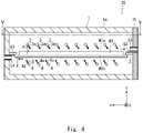
- a workpiece heating apparatus 20 has the same configuration as the workpiece heating apparatus 10 has (see Figs. 1 to 3 ) except that a nozzle 4a, exhaust ports 53 and 54, and shielding plates 63 and 64 are further included.
- the nozzle 4a has the same configuration as the nozzle 3a has, and blows superheated steam in a predetermined direction.
- a plurality of the nozzles 4a are arranged below the frame 2 in the internal space of the housing 1 through a frame (not shown) and a pipe 4, etc.
- the plurality of nozzles 4a are arranged so that each axis is inclined in a direction opposite to one direction along one main surface W1a (to the positive side in the x-axis direction of the example) with respect to a normal of the other main surface W1b.
- the nozzle 3a and the nozzle 4a sandwich the frame 2 and the resin workpiece W1 supported by the frame 2.
- the plurality of nozzles 4a blows superheated steam in a direction opposite to the direction in which the nozzle 3a blows superheated steam (on the positive side in the x-axis direction of the example).
- a blowing angle ⁇ at which the axis of the nozzle 4a and the main surface W1b on which the superheated steam is blown from the nozzle 4a intersect each other is within a range of between 0 (zero) ° and 90 °.
- the superheated steam which is blown from the nozzle 4a comes into contact with the surface of the resin workpiece W1 and then flows there along in a direction opposite to the direction in which superheated stem is blown from the nozzle 3a.
- the nozzle 4a is provided in the pipe 4 to which superheated steam is supplied from the superheated steam tank 3b.
- a plurality of pipes 4 are arranged in a direction in which superheated steam is blown (on the positive side in the x-axis direction of the example) so that there is a predetermined interval between each pipe 4 and the frame 2.
- the axis of the pipe 4 extends in a direction roughly parallel to the other main surface W1b of the resin workpiece W1 (in the y-axis direction of the example).
- a plurality of nozzles 4a are arranged along an axial direction of the pipe 4.
- the exhaust port 53 is provided on the downstream side of the superheated steam supplied from the nozzle 3a, and the exhaust port 54 is provided on the downstream side of the superheated steam supplied from the nozzle 4a.
- the exhaust ports 53 and 54 can discharge superheated steam from the internal space of the workpiece heating apparatus 20 to outside the workpiece heating apparatus 20.
- the shielding plate 64 is provided in the housing body 1a between the frame 2 and the exhaust port 54.
- the shielding plate 63 is provided in the door 1b between the frame 2 and the exhaust port 53. That is, the shielding plates 63 and 64 are respectively provided at both ends of the resin workpiece W1.
- a size of a space between one end of the resin workpiece W1 and the shielding plate 63 may be a size in which the resin workpiece W1 and the shielding plate 63 mechanically do not interfere with each other even when the resin workpiece W1 is thermally expanded by superheated steam, and may be a size capable of securing shielding performance of the required superheated steam.
- a size of a space between one end of the resin workpiece W1 and the shielding plate 64 may be a size in which the resin workpiece W1 and the shielding plate 64 mechanically do not interfere with each other even when the resin workpiece W1 is thermally expanded by superheated steam, and may be a size capable of securing shielding performance of the required superheated steam.
- the shielding panel 63 shields superheated steam supplied from the nozzle 3a and thus prevents the superheated steam from entering the side of the main surface W1b in the internal space of the housing body 1a. Accordingly, the superheated steam stays in the vicinity of the exhaust port 53 so as to be easily discharged therefrom to outside the housing body 1a.
- the shielding panel 64 shields superheated steam supplied from the nozzle 4a and thus prevents the superheated steam from entering the side of the main surface W1a in the internal space of the housing body 1a. Accordingly, the superheated steam stays in the vicinity of the exhaust port 54 so as to be easily discharged therefrom to outside the housing body 1a.
- a heating process for heating the resin workpiece W1 using the workpiece heating apparatus 20 will now be described.
- the door 1b of the workpiece heating apparatus 20 is opened, the resin workpiece W1 is placed on the frame 2, and then the door 1b is closed.
- a plurality of nozzles 4a are arranged so that each axis is inclined in one direction along the main surface W1b of the planar part of the resin workpiece W1 with respect to a normal of the planar part thereof in the same manner that the plurality of nozzles 3a are. In this state, superheated steam is blown on the resin workpiece W1 from the plurality of nozzles 3a and 4a.
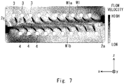
- the superheated steam blown from the plurality of nozzles 3a and 4a comes into contact with the main surfaces W1a and W1b of the resin workpiece W1, and then uniformly flows along the main surfaces W1a and W1b of the resin workpiece W1.
- the superheated steam which has flowed along the main surfaces W1a and W1b of the resin workpiece W1 transmits heat to each part of the main surfaces W1a and W1b in contact with the superheated steam.
- the heat is transmitted to each part of the main surfaces W1a and W1b of the resin workpiece W1 with which the superheated steam successively comes into contact.
- the resin workpiece W1 can be uniformly heated without increasing the number of the nozzles 3a and 4a to be installed per area in the respective main surfaces W1a and W1b.
- the cost can be prevented from increasing.
- the exhaust ports 53 and 54 discharge the superheated steam which has flowed along the resin workpiece W1 to outside the work heating apparatus 20. Therefore, new superheated steam can be successively blown on the resin workpiece W1. Thus, new superheated steam successively flows along the resin workpiece W1 so that the superheated steam can provide heat thereto. Accordingly, the resin workpiece W1 can be heated quickly.
- the shielding plate 63 shields this superheated steam. Therefore, the exhaust port 53 can discharge superheated steam more easily.
- new superheated steam successively flows along the main surface W1a of the resin workpiece W1 so that the superheated steam can provide heat to the resin workpiece W1.
- the shielding plate 64 shields this superheated steam. Therefore, the exhaust port 54 can discharge superheated steam more easily.
- new superheated steam successively flows along the main surface W1b of the resin workpiece W1 so that the superheated steam can provide heat to the resin workpiece W1. Accordingly, the resin workpiece W1 can be further heated quickly.
- a workpiece heating apparatus 30 has the same configuration as the workpiece heating apparatus 10 has (see Figs. 1 to 3 ) except that a nozzle 41a, exhaust ports 53 and 541, and shielding plates 63 and 641 are further included.
- the workpiece apparatus 30 includes the nozzle 41a, the exhaust ports 53 and 541, and the shielding plates 63 and 641.
- the nozzle 41a has the same configuration as the nozzle 4a has (see Figs. 4 and 5 ), and is disposed in a direction different from that of the nozzle 4a.
- the plurality of nozzles 41a are arranged so that each axis is inclined in the same direction as one direction along one main surface W1a (to the negative side in the x-axis direction of the example) with respect to a normal of the other main surface W1b.
- the nozzle 3a and the nozzle 41a sandwich the frame 2 and the resin workpiece W1 supported by the frame 2.
- the plurality of nozzles 41a blows superheated steam in the same direction as the direction in which the nozzle 3a blows superheated steam (on the negative side in the x-axis direction of the example).
- a blowing angle ⁇ at which the axis of the nozzle 41a and the main surface W1b on which the superheated steam is blown from the nozzle 41a intersect each other is within a range of between 0 (zero) ° and 90 °.
- the superheated steam which is blown from the nozzle 41a comes into contact with the main surface W1b of the resin workpiece W1 and then flows there along in the same direction as the direction in which superheated stem is blown from the nozzle 3a.
- the example of the nozzle 41a shown in Fig .6 has the same configuration as the example of the nozzle 4a has.
- the exhaust port 541 is provided on the downstream side of the superheated steam supplied form the nozzle 41a.
- the exhaust port 541 can discharge superheated steam from the internal space of the workpiece heating apparatus 30 to outside the workpiece heating apparatus 30.
- the shielding plate 641 is provided in the door 1b between the frame 2 and the exhaust port 541.
- the shielding plate 641 is provided at one end of the resin workpiece W1.
- a size of a space between one end of the resin workpiece W1 and the shielding plate 641 may be a size in which the resin workpiece W1 and the shielding plate 641 mechanically do not interfere with each other even when the resin workpiece W1 is thermally expanded by superheated steam, and may be a size capable of securing shielding performance of the required superheated steam.
- the shielding panel 641 shields superheated steam supplied from the nozzle 41a and thus prevents the superheated steam from entering the side of the main surface W1a in the internal space of the housing body 1a. Accordingly, the superheated steam stays in the vicinity of the exhaust port 541 so as to be easily discharged therefrom to outside the housing body 1a.
- a heating process for heating the resin workpiece W1 using the workpiece heating apparatus 30 will now be described.
- the door 1b of the workpiece heating apparatus 30 is opened, the resin workpiece W1 is placed on the frame 2, and then the door 1b is closed.
- a plurality of nozzles 41a are arranged so that each axis is inclined in one direction along the main surface W1b of the planar part of the resin workpiece W1 with respect to a normal of the planar part thereof in the same manner that the plurality of nozzles 3a are. In this state, superheated steam is blown on the resin workpiece W1 from the plurality of nozzles 3 a and 41a.
- the superheated steam blown from the plurality of nozzles 3a and 41a comes into contact with the main surfaces W1a and W1b of the resin workpiece W1, and then uniformly flows along the main surfaces W1a and W1b of the resin workpiece W1.
- the superheated steam which has flowed along the main surfaces W1a and W1b of the resin workpiece W1 transmits heat to each part of the main surfaces W1a and W1b in contact with the superheated steam.
- the heat is transmitted to each part of the main surfaces W1a and W1b of the resin workpiece W1 with which the superheated steam successively comes into contact.
- the resin workpiece W1 can be uniformly heated without increasing the number of the nozzles 3a and 41a to be installed per area in each of the main surfaces W1a and W1b.
- the cost can be prevented from increasing.
- the workpiece heating apparatus 20 (see Figs. 4 and 5 ) according to t the second embodiment includes the exhaust ports 53 and 54, but may include technical discharge means for discharging superheated steam.
- the workpiece heating apparatus 20 includes the shielding plates 63 and 64, but may include shielding members having various shapes other than a flat plate shape. Examples of the shape of such shielding members include a curved plate, a flat plate having a curved shape or a fin shape at a part thereof, and the like. Further, the workpiece heating apparatus 10 (see Figs. 1 to 3 ) may further include the exhaust port 53 and the shielding plate 63 as appropriate.
Landscapes
- Engineering & Computer Science (AREA)
- Physics & Mathematics (AREA)
- Thermal Sciences (AREA)
- Mechanical Engineering (AREA)
- Health & Medical Sciences (AREA)
- Oral & Maxillofacial Surgery (AREA)
- Life Sciences & Earth Sciences (AREA)
- Microbiology (AREA)
- General Engineering & Computer Science (AREA)
- Heating, Cooling, Or Curing Plastics Or The Like In General (AREA)
- Processing And Handling Of Plastics And Other Materials For Molding In General (AREA)
Claims (4)
- Verfahren zum Erwärmen eines Harzwerkstücks, das einen Heizprozess zum Auftragen von überhitztem Dampf aus einer Vielzahl von Düsen (3a, 4a und 41a) umfasst, um das Harzwerkstück (W1), welches einen ebenen Teil aufweist, zu erwärmen, wobei
bei dem Erwärmungsprozess der überhitzte Dampf aus der Vielzahl von Düsen (3a, 4a und 41a) auf das Harzwerkstück (W1) geblasen wird, um das Harzwerkstück in einem Zustand zu erwärmen, in dem jede Achse der Vielzahl von Düsen (3a, 4a und 41a) so angeordnet ist, dass sie in einer Richtung entlang einer Ebene (W1a und W1b) des ebenen Teils in Bezug auf eine Normale des ebenen Teils geneigt ist. - Verfahren zum Erwärmen eines Harzwerkstücks nach Anspruch 1, wobei das Harzwerkstück (W1) ein ebener Körper mit einer Hauptoberfläche (W1a) und einer anderen Hauptoberfläche (W1b) ist, und wobei die Vielzahl von Düsen (3a, 4a und 41a) eine Vielzahl von ersten Düsen (3a) und eine Vielzahl von zweiten Düsen (4a) umfasst,bei dem Erwärmungsprozess in der einen Hauptoberfläche (W1a) des ebenen Körpers die Vielzahl von ersten Düsen (3a) so angeordnet sind, dass jede Achse in einer Richtung entlang der einen Hauptoberfläche (W1a) in Bezug auf eine Normale der einen Hauptoberfläche (W1a) geneigt ist, undin der anderen Hauptoberfläche (W1b) des ebenen Körpers die Vielzahl der zweiten Düsen (4a) so angeordnet sind, dass jede Achse in einer Richtung entgegengesetzt zu der einen Richtung in Bezug auf eine Normale der anderen Hauptoberfläche (W1b) geneigt ist.
- Verfahren zum Erwärmen eines Harzwerkstücks nach Anspruch 1 oder 2, das ferner die Verwendung von Auslassmitteln (5, 53, 54, 541) zum Auslassen des überhitzten Dampfes umfasst, wobei die Auslassmittel (5, 53, 54, 541) auf der stromabwärtigen Seite des überhitzten Dampfes in Bezug auf das Harzwerkstück (W1) vorgesehen sind.
- Verfahren zum Erwärmen eines Harzwerkstücks nach Anspruch 3, das ferner die Verwendung von Abschirmelementen (63, 64, 641) umfasst, wobei die Abschirmelemente an den beiden Enden des Harzwerkstücks (W1) vorgesehen sind, um den überhitzten Dampf abzuschirmen.
Applications Claiming Priority (1)
| Application Number | Priority Date | Filing Date | Title |
|---|---|---|---|
| JP2018027259A JP7115673B2 (ja) | 2018-02-19 | 2018-02-19 | ワークの製造方法 |
Publications (2)
| Publication Number | Publication Date |
|---|---|
| EP3552789A1 EP3552789A1 (de) | 2019-10-16 |
| EP3552789B1 true EP3552789B1 (de) | 2023-01-04 |
Family
ID=64755169
Family Applications (1)
| Application Number | Title | Priority Date | Filing Date |
|---|---|---|---|
| EP18214633.2A Active EP3552789B1 (de) | 2018-02-19 | 2018-12-20 | Verfahren zum heizen eines werkstücks aus harz |
Country Status (4)
| Country | Link |
|---|---|
| US (1) | US20190255743A1 (de) |
| EP (1) | EP3552789B1 (de) |
| JP (1) | JP7115673B2 (de) |
| CN (1) | CN110171084A (de) |
Families Citing this family (3)
| Publication number | Priority date | Publication date | Assignee | Title |
|---|---|---|---|---|
| US11137208B2 (en) * | 2017-09-19 | 2021-10-05 | Chubu Electric Power Co., Inc. | Heating device and heating method, each of which uses superheated steam |
| JP7163899B2 (ja) * | 2019-11-21 | 2022-11-01 | トヨタ自動車株式会社 | ワーク製造システム及びワークの製造方法 |
| KR102244854B1 (ko) * | 2020-08-13 | 2021-04-27 | 주식회사 세원전자 | 열수축 튜브에 대한 차별적 가열이 가능한 가열장치 |
Citations (2)
| Publication number | Priority date | Publication date | Assignee | Title |
|---|---|---|---|---|
| WO2012060159A1 (ja) * | 2010-11-04 | 2012-05-10 | 新熱工業株式会社 | 樹脂材料の炭化処理方法及び炭化処理装置 |
| JP2013253758A (ja) * | 2012-06-08 | 2013-12-19 | Toyota Motor Corp | 熱処理方法、及び熱処理炉 |
Family Cites Families (15)
| Publication number | Priority date | Publication date | Assignee | Title |
|---|---|---|---|---|
| GB1521037A (en) | 1975-08-07 | 1978-08-09 | Plastona Waddington Ltd John | Manufacture of thin walled plastics articles by thermoforming |
| JPH0611139Y2 (ja) * | 1988-07-20 | 1994-03-23 | 西田汽罐工業株式会社 | マットの裏貼加硫装置 |
| JPH04265735A (ja) * | 1991-02-21 | 1992-09-21 | Matsushita Electric Works Ltd | 板状体の加熱方法とそのための装置 |
| JP4352047B2 (ja) | 2003-03-04 | 2009-10-28 | 三菱レイヨン株式会社 | シート状物の熱処理装置および熱処理方法 |
| CN100396464C (zh) * | 2003-03-04 | 2008-06-25 | 三菱丽阳株式会社 | 片状物的热处理装置及热处理方法 |
| JP2006239712A (ja) * | 2005-03-01 | 2006-09-14 | Daiichi Denki Kk | 加熱成形方法及びシステム |
| JP5118861B2 (ja) | 2007-03-02 | 2013-01-16 | フタムラ化学株式会社 | 熱可塑性フィルムの製造方法 |
| CN101303096A (zh) | 2007-08-09 | 2008-11-12 | 章明伟 | 钢塑复合管材制造设备及钢塑复合管材的制造方法 |
| JP4393576B1 (ja) * | 2008-09-03 | 2010-01-06 | 新熱工業株式会社 | 電気機器の分解方法 |
| EP2692508B1 (de) * | 2011-03-29 | 2018-12-19 | Toray Industries, Inc. | Spannrahmenofen und verfahren zur herstellung eines gestreckten films |
| JP5909927B2 (ja) * | 2011-08-30 | 2016-04-27 | セイコーエプソン株式会社 | 記録装置 |
| JP5784192B1 (ja) * | 2014-07-04 | 2015-09-24 | 株式会社日本製鋼所 | フィルム延伸装置、及びフィルム延伸方法 |
| JP6800569B2 (ja) | 2014-10-03 | 2020-12-16 | 中部電力株式会社 | 金属製品、炭素繊維材料又は樹脂材料の加熱装置 |
| CN206455869U (zh) * | 2017-01-25 | 2017-09-01 | 延锋汽车饰件模具技术有限公司 | 一种烘箱模具温度均匀性调整装置 |
| US11137208B2 (en) * | 2017-09-19 | 2021-10-05 | Chubu Electric Power Co., Inc. | Heating device and heating method, each of which uses superheated steam |
-
2018
- 2018-02-19 JP JP2018027259A patent/JP7115673B2/ja active Active
- 2018-12-20 EP EP18214633.2A patent/EP3552789B1/de active Active
-
2019
- 2019-01-04 US US16/239,581 patent/US20190255743A1/en not_active Abandoned
- 2019-02-18 CN CN201910119590.2A patent/CN110171084A/zh active Pending
Patent Citations (2)
| Publication number | Priority date | Publication date | Assignee | Title |
|---|---|---|---|---|
| WO2012060159A1 (ja) * | 2010-11-04 | 2012-05-10 | 新熱工業株式会社 | 樹脂材料の炭化処理方法及び炭化処理装置 |
| JP2013253758A (ja) * | 2012-06-08 | 2013-12-19 | Toyota Motor Corp | 熱処理方法、及び熱処理炉 |
Also Published As
| Publication number | Publication date |
|---|---|
| JP7115673B2 (ja) | 2022-08-09 |
| US20190255743A1 (en) | 2019-08-22 |
| CN110171084A (zh) | 2019-08-27 |
| JP2019142065A (ja) | 2019-08-29 |
| EP3552789A1 (de) | 2019-10-16 |
Similar Documents
| Publication | Publication Date | Title |
|---|---|---|
| EP3552789A1 (de) | Verfahren zur herstellung eines werkstücks | |
| JP6513392B2 (ja) | 温度制御を向上させた防氷ノズル | |
| KR101770576B1 (ko) | 동축 레이저 보조형 콜드 스프레이 노즐 | |
| US10814367B2 (en) | Method for the homogeneous non-contact temperature control of non-endless surfaces which are to be temperature-controlled, and device therefor | |
| CA2865853C (en) | Aircraft anti-icing systems having deflector vanes | |
| US10072900B2 (en) | Heat exchanger distributor with intersecting streams | |
| KR20030022168A (ko) | 구조 부재들을 성형하기 위한 방법 및 장치 | |
| US9995250B2 (en) | Exhaust gas heat exchanger | |
| KR20160041996A (ko) | 열처리된 금속 제품용 분사 담금질 시스템 | |
| US6983696B2 (en) | Apparatus for cooling material to be printed and printing units at sheet fed printing machines with cooled compressed air | |
| US10625321B2 (en) | Cooling apparatus and cooling method for steel material | |
| US20200309408A1 (en) | Heat exchanger for gas appliance and method for manufacturing heat exchanger for gas appliance | |
| KR102487730B1 (ko) | 금속 부품의 부분 열처리를 위한 템퍼링 스테이션 | |
| KR20220043161A (ko) | 응력 패턴 약화 효과가 있는 곡면 유리 강화 장치 | |
| TW202003111A (zh) | 氣體噴出噴嘴及爐、以及加工薄膜的製造方法 | |
| US20230019923A1 (en) | Temperature-control device for partially cooling a component | |
| US20180141242A1 (en) | Apparatus for carrying a fiber composite resin system in a heat transfer device | |
| US20230304116A1 (en) | Thermal Treatment of Component | |
| CN210506065U (zh) | 一种具有应力斑弱化效果的曲面玻璃钢化设备 | |
| JP4388499B2 (ja) | パイプの冷却設備および冷却方法 | |
| KR20170006492A (ko) | 충돌형 온도균일화 장치 | |
| US10507485B2 (en) | Drying system employing compressed air | |
| JP2025098577A (ja) | レーザー照射溶接装置のエアー供給装置 | |
| CN211546615U (zh) | 喷嘴 | |
| JPH0820655A (ja) | 表面溶融処理装置 |
Legal Events
| Date | Code | Title | Description |
|---|---|---|---|
| PUAI | Public reference made under article 153(3) epc to a published international application that has entered the european phase |
Free format text: ORIGINAL CODE: 0009012 |
|
| STAA | Information on the status of an ep patent application or granted ep patent |
Free format text: STATUS: REQUEST FOR EXAMINATION WAS MADE |
|
| 17P | Request for examination filed |
Effective date: 20181220 |
|
| AK | Designated contracting states |
Kind code of ref document: A1 Designated state(s): AL AT BE BG CH CY CZ DE DK EE ES FI FR GB GR HR HU IE IS IT LI LT LU LV MC MK MT NL NO PL PT RO RS SE SI SK SM TR |
|
| AX | Request for extension of the european patent |
Extension state: BA ME |
|
| REG | Reference to a national code |
Ref country code: DE Ref legal event code: R079 Ref document number: 602018044974 Country of ref document: DE Free format text: PREVIOUS MAIN CLASS: B29B0013020000 Ipc: F26B0003040000 |
|
| RIC1 | Information provided on ipc code assigned before grant |
Ipc: B29C 51/42 20060101ALI20220525BHEP Ipc: B29C 35/04 20060101ALI20220525BHEP Ipc: B29B 13/02 20060101ALI20220525BHEP Ipc: F26B 3/04 20060101AFI20220525BHEP |
|
| GRAP | Despatch of communication of intention to grant a patent |
Free format text: ORIGINAL CODE: EPIDOSNIGR1 |
|
| STAA | Information on the status of an ep patent application or granted ep patent |
Free format text: STATUS: GRANT OF PATENT IS INTENDED |
|
| INTG | Intention to grant announced |
Effective date: 20220722 |
|
| GRAS | Grant fee paid |
Free format text: ORIGINAL CODE: EPIDOSNIGR3 |
|
| GRAA | (expected) grant |
Free format text: ORIGINAL CODE: 0009210 |
|
| STAA | Information on the status of an ep patent application or granted ep patent |
Free format text: STATUS: THE PATENT HAS BEEN GRANTED |
|
| RIN1 | Information on inventor provided before grant (corrected) |
Inventor name: IMAMURA, YUKINORI Inventor name: OSA, NOBURO Inventor name: SAKUI, TAKASHI Inventor name: MATSUMOTO, YUSUKE |
|
| AK | Designated contracting states |
Kind code of ref document: B1 Designated state(s): AL AT BE BG CH CY CZ DE DK EE ES FI FR GB GR HR HU IE IS IT LI LT LU LV MC MK MT NL NO PL PT RO RS SE SI SK SM TR |
|
| REG | Reference to a national code |
Ref country code: GB Ref legal event code: FG4D |
|
| REG | Reference to a national code |
Ref country code: CH Ref legal event code: EP |
|
| REG | Reference to a national code |
Ref country code: AT Ref legal event code: REF Ref document number: 1542204 Country of ref document: AT Kind code of ref document: T Effective date: 20230115 |
|
| REG | Reference to a national code |
Ref country code: DE Ref legal event code: R096 Ref document number: 602018044974 Country of ref document: DE |
|
| REG | Reference to a national code |
Ref country code: IE Ref legal event code: FG4D |
|
| REG | Reference to a national code |
Ref country code: LT Ref legal event code: MG9D |
|
| REG | Reference to a national code |
Ref country code: NL Ref legal event code: MP Effective date: 20230104 |
|
| REG | Reference to a national code |
Ref country code: AT Ref legal event code: MK05 Ref document number: 1542204 Country of ref document: AT Kind code of ref document: T Effective date: 20230104 |
|
| PG25 | Lapsed in a contracting state [announced via postgrant information from national office to epo] |
Ref country code: NL Free format text: LAPSE BECAUSE OF FAILURE TO SUBMIT A TRANSLATION OF THE DESCRIPTION OR TO PAY THE FEE WITHIN THE PRESCRIBED TIME-LIMIT Effective date: 20230104 |
|
| PG25 | Lapsed in a contracting state [announced via postgrant information from national office to epo] |
Ref country code: RS Free format text: LAPSE BECAUSE OF FAILURE TO SUBMIT A TRANSLATION OF THE DESCRIPTION OR TO PAY THE FEE WITHIN THE PRESCRIBED TIME-LIMIT Effective date: 20230104 Ref country code: PT Free format text: LAPSE BECAUSE OF FAILURE TO SUBMIT A TRANSLATION OF THE DESCRIPTION OR TO PAY THE FEE WITHIN THE PRESCRIBED TIME-LIMIT Effective date: 20230504 Ref country code: NO Free format text: LAPSE BECAUSE OF FAILURE TO SUBMIT A TRANSLATION OF THE DESCRIPTION OR TO PAY THE FEE WITHIN THE PRESCRIBED TIME-LIMIT Effective date: 20230404 Ref country code: LV Free format text: LAPSE BECAUSE OF FAILURE TO SUBMIT A TRANSLATION OF THE DESCRIPTION OR TO PAY THE FEE WITHIN THE PRESCRIBED TIME-LIMIT Effective date: 20230104 Ref country code: LT Free format text: LAPSE BECAUSE OF FAILURE TO SUBMIT A TRANSLATION OF THE DESCRIPTION OR TO PAY THE FEE WITHIN THE PRESCRIBED TIME-LIMIT Effective date: 20230104 Ref country code: HR Free format text: LAPSE BECAUSE OF FAILURE TO SUBMIT A TRANSLATION OF THE DESCRIPTION OR TO PAY THE FEE WITHIN THE PRESCRIBED TIME-LIMIT Effective date: 20230104 Ref country code: ES Free format text: LAPSE BECAUSE OF FAILURE TO SUBMIT A TRANSLATION OF THE DESCRIPTION OR TO PAY THE FEE WITHIN THE PRESCRIBED TIME-LIMIT Effective date: 20230104 Ref country code: AT Free format text: LAPSE BECAUSE OF FAILURE TO SUBMIT A TRANSLATION OF THE DESCRIPTION OR TO PAY THE FEE WITHIN THE PRESCRIBED TIME-LIMIT Effective date: 20230104 |
|
| PG25 | Lapsed in a contracting state [announced via postgrant information from national office to epo] |
Ref country code: SE Free format text: LAPSE BECAUSE OF FAILURE TO SUBMIT A TRANSLATION OF THE DESCRIPTION OR TO PAY THE FEE WITHIN THE PRESCRIBED TIME-LIMIT Effective date: 20230104 Ref country code: PL Free format text: LAPSE BECAUSE OF FAILURE TO SUBMIT A TRANSLATION OF THE DESCRIPTION OR TO PAY THE FEE WITHIN THE PRESCRIBED TIME-LIMIT Effective date: 20230104 Ref country code: IS Free format text: LAPSE BECAUSE OF FAILURE TO SUBMIT A TRANSLATION OF THE DESCRIPTION OR TO PAY THE FEE WITHIN THE PRESCRIBED TIME-LIMIT Effective date: 20230504 Ref country code: GR Free format text: LAPSE BECAUSE OF FAILURE TO SUBMIT A TRANSLATION OF THE DESCRIPTION OR TO PAY THE FEE WITHIN THE PRESCRIBED TIME-LIMIT Effective date: 20230405 Ref country code: FI Free format text: LAPSE BECAUSE OF FAILURE TO SUBMIT A TRANSLATION OF THE DESCRIPTION OR TO PAY THE FEE WITHIN THE PRESCRIBED TIME-LIMIT Effective date: 20230104 |
|
| REG | Reference to a national code |
Ref country code: DE Ref legal event code: R097 Ref document number: 602018044974 Country of ref document: DE |
|
| PG25 | Lapsed in a contracting state [announced via postgrant information from national office to epo] |
Ref country code: SM Free format text: LAPSE BECAUSE OF FAILURE TO SUBMIT A TRANSLATION OF THE DESCRIPTION OR TO PAY THE FEE WITHIN THE PRESCRIBED TIME-LIMIT Effective date: 20230104 Ref country code: RO Free format text: LAPSE BECAUSE OF FAILURE TO SUBMIT A TRANSLATION OF THE DESCRIPTION OR TO PAY THE FEE WITHIN THE PRESCRIBED TIME-LIMIT Effective date: 20230104 Ref country code: EE Free format text: LAPSE BECAUSE OF FAILURE TO SUBMIT A TRANSLATION OF THE DESCRIPTION OR TO PAY THE FEE WITHIN THE PRESCRIBED TIME-LIMIT Effective date: 20230104 Ref country code: DK Free format text: LAPSE BECAUSE OF FAILURE TO SUBMIT A TRANSLATION OF THE DESCRIPTION OR TO PAY THE FEE WITHIN THE PRESCRIBED TIME-LIMIT Effective date: 20230104 Ref country code: CZ Free format text: LAPSE BECAUSE OF FAILURE TO SUBMIT A TRANSLATION OF THE DESCRIPTION OR TO PAY THE FEE WITHIN THE PRESCRIBED TIME-LIMIT Effective date: 20230104 |
|
| PLBE | No opposition filed within time limit |
Free format text: ORIGINAL CODE: 0009261 |
|
| STAA | Information on the status of an ep patent application or granted ep patent |
Free format text: STATUS: NO OPPOSITION FILED WITHIN TIME LIMIT |
|
| PG25 | Lapsed in a contracting state [announced via postgrant information from national office to epo] |
Ref country code: SK Free format text: LAPSE BECAUSE OF FAILURE TO SUBMIT A TRANSLATION OF THE DESCRIPTION OR TO PAY THE FEE WITHIN THE PRESCRIBED TIME-LIMIT Effective date: 20230104 |
|
| 26N | No opposition filed |
Effective date: 20231005 |
|
| PG25 | Lapsed in a contracting state [announced via postgrant information from national office to epo] |
Ref country code: SI Free format text: LAPSE BECAUSE OF FAILURE TO SUBMIT A TRANSLATION OF THE DESCRIPTION OR TO PAY THE FEE WITHIN THE PRESCRIBED TIME-LIMIT Effective date: 20230104 |
|
| PG25 | Lapsed in a contracting state [announced via postgrant information from national office to epo] |
Ref country code: IT Free format text: LAPSE BECAUSE OF FAILURE TO SUBMIT A TRANSLATION OF THE DESCRIPTION OR TO PAY THE FEE WITHIN THE PRESCRIBED TIME-LIMIT Effective date: 20230104 |
|
| REG | Reference to a national code |
Ref country code: DE Ref legal event code: R119 Ref document number: 602018044974 Country of ref document: DE |
|
| REG | Reference to a national code |
Ref country code: CH Ref legal event code: PL |
|
| PG25 | Lapsed in a contracting state [announced via postgrant information from national office to epo] |
Ref country code: LU Free format text: LAPSE BECAUSE OF NON-PAYMENT OF DUE FEES Effective date: 20231220 |
|
| PG25 | Lapsed in a contracting state [announced via postgrant information from national office to epo] |
Ref country code: MC Free format text: LAPSE BECAUSE OF FAILURE TO SUBMIT A TRANSLATION OF THE DESCRIPTION OR TO PAY THE FEE WITHIN THE PRESCRIBED TIME-LIMIT Effective date: 20230104 |
|
| GBPC | Gb: european patent ceased through non-payment of renewal fee |
Effective date: 20231220 |
|
| REG | Reference to a national code |
Ref country code: BE Ref legal event code: MM Effective date: 20231231 |
|
| PG25 | Lapsed in a contracting state [announced via postgrant information from national office to epo] |
Ref country code: MC Free format text: LAPSE BECAUSE OF FAILURE TO SUBMIT A TRANSLATION OF THE DESCRIPTION OR TO PAY THE FEE WITHIN THE PRESCRIBED TIME-LIMIT Effective date: 20230104 Ref country code: LU Free format text: LAPSE BECAUSE OF NON-PAYMENT OF DUE FEES Effective date: 20231220 |
|
| REG | Reference to a national code |
Ref country code: IE Ref legal event code: MM4A |
|
| PG25 | Lapsed in a contracting state [announced via postgrant information from national office to epo] |
Ref country code: DE Free format text: LAPSE BECAUSE OF NON-PAYMENT OF DUE FEES Effective date: 20240702 Ref country code: IE Free format text: LAPSE BECAUSE OF NON-PAYMENT OF DUE FEES Effective date: 20231220 |
|
| PG25 | Lapsed in a contracting state [announced via postgrant information from national office to epo] |
Ref country code: GB Free format text: LAPSE BECAUSE OF NON-PAYMENT OF DUE FEES Effective date: 20231220 |
|
| PG25 | Lapsed in a contracting state [announced via postgrant information from national office to epo] |
Ref country code: BE Free format text: LAPSE BECAUSE OF NON-PAYMENT OF DUE FEES Effective date: 20231231 |
|
| PG25 | Lapsed in a contracting state [announced via postgrant information from national office to epo] |
Ref country code: FR Free format text: LAPSE BECAUSE OF NON-PAYMENT OF DUE FEES Effective date: 20231231 |
|
| PG25 | Lapsed in a contracting state [announced via postgrant information from national office to epo] |
Ref country code: CH Free format text: LAPSE BECAUSE OF NON-PAYMENT OF DUE FEES Effective date: 20231231 |
|
| PG25 | Lapsed in a contracting state [announced via postgrant information from national office to epo] |
Ref country code: IE Free format text: LAPSE BECAUSE OF NON-PAYMENT OF DUE FEES Effective date: 20231220 Ref country code: GB Free format text: LAPSE BECAUSE OF NON-PAYMENT OF DUE FEES Effective date: 20231220 Ref country code: FR Free format text: LAPSE BECAUSE OF NON-PAYMENT OF DUE FEES Effective date: 20231231 Ref country code: DE Free format text: LAPSE BECAUSE OF NON-PAYMENT OF DUE FEES Effective date: 20240702 Ref country code: CH Free format text: LAPSE BECAUSE OF NON-PAYMENT OF DUE FEES Effective date: 20231231 Ref country code: BE Free format text: LAPSE BECAUSE OF NON-PAYMENT OF DUE FEES Effective date: 20231231 |
|
| PG25 | Lapsed in a contracting state [announced via postgrant information from national office to epo] |
Ref country code: BG Free format text: LAPSE BECAUSE OF FAILURE TO SUBMIT A TRANSLATION OF THE DESCRIPTION OR TO PAY THE FEE WITHIN THE PRESCRIBED TIME-LIMIT Effective date: 20230104 |
|
| PG25 | Lapsed in a contracting state [announced via postgrant information from national office to epo] |
Ref country code: BG Free format text: LAPSE BECAUSE OF FAILURE TO SUBMIT A TRANSLATION OF THE DESCRIPTION OR TO PAY THE FEE WITHIN THE PRESCRIBED TIME-LIMIT Effective date: 20230104 |
|
| PG25 | Lapsed in a contracting state [announced via postgrant information from national office to epo] |
Ref country code: CY Free format text: LAPSE BECAUSE OF FAILURE TO SUBMIT A TRANSLATION OF THE DESCRIPTION OR TO PAY THE FEE WITHIN THE PRESCRIBED TIME-LIMIT; INVALID AB INITIO Effective date: 20181220 |
|
| PG25 | Lapsed in a contracting state [announced via postgrant information from national office to epo] |
Ref country code: HU Free format text: LAPSE BECAUSE OF FAILURE TO SUBMIT A TRANSLATION OF THE DESCRIPTION OR TO PAY THE FEE WITHIN THE PRESCRIBED TIME-LIMIT; INVALID AB INITIO Effective date: 20181220 |
|
| PG25 | Lapsed in a contracting state [announced via postgrant information from national office to epo] |
Ref country code: TR Free format text: LAPSE BECAUSE OF FAILURE TO SUBMIT A TRANSLATION OF THE DESCRIPTION OR TO PAY THE FEE WITHIN THE PRESCRIBED TIME-LIMIT Effective date: 20230104 |