EP3552524A1 - Distributeur pour d'avancement de la marchandises - Google Patents
Distributeur pour d'avancement de la marchandises Download PDFInfo
- Publication number
- EP3552524A1 EP3552524A1 EP18166691.8A EP18166691A EP3552524A1 EP 3552524 A1 EP3552524 A1 EP 3552524A1 EP 18166691 A EP18166691 A EP 18166691A EP 3552524 A1 EP3552524 A1 EP 3552524A1
- Authority
- EP
- European Patent Office
- Prior art keywords
- carriage
- rail
- goods
- feed system
- goods feed
- Prior art date
- Legal status (The legal status is an assumption and is not a legal conclusion. Google has not performed a legal analysis and makes no representation as to the accuracy of the status listed.)
- Granted
Links
Images


Classifications
-
- A—HUMAN NECESSITIES
- A47—FURNITURE; DOMESTIC ARTICLES OR APPLIANCES; COFFEE MILLS; SPICE MILLS; SUCTION CLEANERS IN GENERAL
- A47F—SPECIAL FURNITURE, FITTINGS, OR ACCESSORIES FOR SHOPS, STOREHOUSES, BARS, RESTAURANTS OR THE LIKE; PAYING COUNTERS
- A47F1/00—Racks for dispensing merchandise; Containers for dispensing merchandise
- A47F1/04—Racks or containers with arrangements for dispensing articles, e.g. by means of gravity or springs
- A47F1/12—Racks or containers with arrangements for dispensing articles, e.g. by means of gravity or springs dispensing from the side of an approximately horizontal stack
- A47F1/125—Racks or containers with arrangements for dispensing articles, e.g. by means of gravity or springs dispensing from the side of an approximately horizontal stack with an article-pushing device
- A47F1/126—Racks or containers with arrangements for dispensing articles, e.g. by means of gravity or springs dispensing from the side of an approximately horizontal stack with an article-pushing device the pushing device being urged by spring means
Definitions
- the present invention relates to a goods advancing system for the on-sale presentation of goods, comprising a rail with an elongated, extending in a longitudinal direction bottom having a bottom, an upper side, two opposite longitudinal sides, a rear end face and a front end face and the Receiving goods is used, a goods bearing surface defining carriage which is movable on the floor between the end sides in the longitudinal direction between a rear and a front position, and a clamping means which is fixed in the front region of the rail and on the carriage and in the tensioned state the carriage is biased towards the front portion of the rail.
- Goods feed systems of the type mentioned are known in the prior art in a variety of configurations. They serve to position goods always on the front edge of a shelf or a display. This improves on the one hand, the appearance of the shelf or display. On the other hand, the customer is also facilitated the goods access.
- the rails and carriages of goods feed systems that are permanently placed on shelves are usually made of plastic, wherein the bias of the carriage is realized in the direction of the front region of the rail by metallic spring elements.
- a major disadvantage of such material feed systems is that they are very expensive. This is also the reason why they are not used for display systems, ie mostly made of corrugated board Displays in which goods are presented only temporarily as part of sales campaigns.
- material feed systems made of cardboard or corrugated board are known, which are used for a single use directly in aêtumverpackung or in a display.
- a material feed system is for example in the DE 10 2004 015 701 B3 described.
- This includes a rail, a carriage and a clamping device.
- the rail has a serving for receiving goods, elongated and extending in a longitudinal direction bottom with a bottom, a top, two opposite longitudinal sides, a rear end face and a front end side.
- the floor is partially multi-ply and consists of a lower floor layer and two longitudinally extending, transversely to the longitudinal direction spaced apart upper floor layers, which are each formed by a connected to one of the longitudinal sides of the lower bottom layer flap, which on the upper side of the lower bottom layer folded.
- the tensioning means formed by an annular rubber band
- two openings are provided at a distance from each other in the region of the front end side of the bottom, through which the tensioning means is guided.
- the carriage consists of a substantially vertically extending between the longitudinal sides of the bottom of the rail wall and two connected thereto, folded back side walls. In the lower region of the carriage, two passage openings are formed for passing the tensioning means.
- the latter extends from its attachment in the front region of the rail within the recess formed between the two upper floor layers to the carriage, so that the carriage biased in the tensioned state of the tensioning means in the direction of the front portion of the rail and between a rear and a front carriage position between guided the upper floor layers is movable.
- the rail and The carriages are each folded in one piece from a blank of cardboard or corrugated cardboard.
- a disadvantage of in the DE 10 2004 015 701 B3 described product feed system is that this has a relatively low dimensional stability.
- the two upper bottom layers, which are folded onto the lower bottom layer can only be held securely in their position by being positioned on these goods. This proves to be unwieldy especially when equipping the goods feed system with goods.
- Another disadvantage is that the goods contact surface of the carriage due to the fact that the carriage is guided between the two upper floor layers, is relatively small and does not span the entire width of the floor. This leads to the fact that the transfer of the clamping force of the clamping device is unfavorable to the applied to the goods bearing surface goods.
- Yet another disadvantage is that the depth of the carriage is relatively large due to the folded-back side walls. Accordingly, only a part of the rail is available for receiving goods.
- the present invention provides a goods feed system of the type mentioned, which is characterized in that the bottom has a lower, provided with a through hole bottom layer and at least one folded on the lower bottom layer top ground layer, in which an elongated passage opening is formed which is positioned congruent to the through hole and extending longitudinally rearward from the rear to the rear carriage position, and that the clamping means, starting from its attachment in the front region of the rail through the through hole and the elongate passage opening led to the slide.
- the entire rail can be made multi-layered, in particular two-ply, which overall entails high stability, in particular dimensional stability.
- the entire upper surface of the rail can serve as a receiving surface for the carriage, with the result that the goods contact surface of the carriage can be chosen comparatively large and the width of the rail can substantially correspond.
- the clamping force of the clamping means can be transmitted very evenly over the carriage to the voltage applied to the goods bearing surface goods.
- the rail is provided on its front end side with at least one, in particular formed with at least one undercut, forward or upward projecting projection which serves for fastening of the clamping means.
- the projection may in particular be formed on the upper bottom layer, so that the bottom layers are pressed against each other by the tensioning means.
- the projection is formed by two partial projections, which are formed substantially congruently on the one hand on the lower bottom layer and on the other hand on the upper bottom layer. In this way, an even better stability is achieved.
- the rail preferably has at least one upwardly projecting side wall, which adjoins one of the longitudinal sides of the floor and in particular extends over the entire length of the floor. Thanks to such a side wall a guide of the goods arranged on the rail is realized in a simple manner. If only a single side wall is provided, a corresponding side wall of an adjacently arranged goods advance system can take over the guidance of the goods on the rail on the other side. Of course, it is also possible to provide each rail with two side walls opposite each other and extending parallel to each other.
- the rail is made in one piece from a blank made of cardboard or corrugated cardboard and mounted in particular without further aids. Accordingly, the rail can be easily manufactured and assembled. It should be understood, however, that fasteners can be used during assembly, particularly in the form of adhesive, eyelets, adhesive tapes, rivets or the like.
- the upper bottom layer is in particular frontally connected to the lower bottom layer and folded onto the lower bottom layer, resulting in a simple and stable construction of the carriage.
- the carriage preferably has a wall extending substantially vertically between the longitudinal sides of the bottom of the rail, which defines the cloth bearing surface, and a bottom wall connected thereto, which rests on the bottom of the rail, thereby achieving a simple yet stable construction.
- a passage opening for the passage of the tensioning means is advantageously formed so that an engagement with the tensioning means takes place in the lower region of the carriage.
- an upwardly projecting projection for fastening the tensioning means is preferably provided, which is provided in particular with at least one undercut. Accordingly finds also in the upper range of the Sliding an engagement with the clamping means instead, whereby an optimal power transmission from the goods contact surface of the carriage to the voltage applied to this product can be realized.
- a through hole for passing the clamping means may be formed, which is a good power transmission from the clamping means on the carriage beneficial.
- the carriage advantageously has substantially vertically extending side walls which laterally interconnect the substantially vertically extending wall and the bottom wall, thereby further improving the stability of the carriage.
- the bottom wall of the carriage may be multi-layered, which also serves to improve the stability of the carriage.
- Locking means are preferably provided, which are designed to lock the carriage on the rail in the rear carriage position. In the locked state, the fabric feed system can then be easily equipped with goods, whereupon the lock is released to activate the goods feed.
- the locking means may, for example, comprise at least one latching projection projecting downwards from the bottom wall of the carriage and at least one latching recess formed in the rail in the region of the rear slide position and cooperating with the at least one latching projection, or vice versa.
- the carriage is made of a single blank of cardboard or corrugated board and mounted in particular without further aids. Accordingly, the carriage can be easily manufactured and assembled. It should be understood, however, that fasteners may be used during assembly, particularly in the form of adhesive, eyelets, adhesive tapes, rivets or the like
- connecting elements are provided on the longitudinal sides of the bottom of the rail, which are designed to connect the bottoms of the rails laterally adjacent to each other
- the connecting elements are formed in particular in the form of connecting projections and connecting recesses whose dimensions are adapted to each other and in particular interlock positively.
- the tensioning means is preferably formed by an annular rubber band.
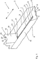
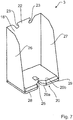
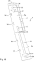
- FIGS. 1 and 2 show a cloth feed system 1 according to a first embodiment of the present invention, which has as a main components a rail 2, a carriage 3 and a tensioning means 4.
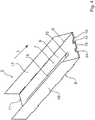
- the in the Figures 3 and 4 Rail 2 shown in detail is folded from a one-piece blank made of cardboard or corrugated cardboard. It comprises an elongated, extending in a longitudinal direction L bottom 5, which has a bottom 6, an upper side 7, two opposite longitudinal sides 8 and 9, a front end face 10 and a rear end face 11 and serves to receive goods.
- the bottom 5 in the present case consists of a lower bottom layer 5a and an upper bottom layer 5b, which have substantially the same outer dimensions, along the rear end face 11 of the bottom 5 connected to each other and in the direction of arrow A in FIG FIG. 3 folded on each other.
- the lower bottom layer 5a is provided in the front region with a centrally arranged through hole 12 in the present case.
- an elongated passage opening 13 is formed, which is positioned in the folded state of the rail 2 congruent to the through hole 12 and extending from this in the longitudinal direction L to the rear.
- forward projecting projection 15 is formed, which serves for fastening of the clamping means 4. More specifically, the projection 15 consists of two congruently arranged one above the other partial projections, which are frontally formed on the lower bottom layer 5a and the upper bottom layer 5b.
- the rail 2 comprises two upwardly projecting side walls 16 and 17, which adjoin the longitudinal sides 8 and 9 of the bottom 5 and extend in the present case over the entire length of the bottom 5.
- the upper bottom layer 5b is folded onto the lower bottom layer 5a. Further, the side walls 17 and 17 are folded upwards by 90 °, respectively.
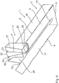
- Carriage 3 shown in detail is also made of a single blank of cardboard or corrugated board. It comprises a mounted in the state of the goods feed system 1 substantially vertically between the longitudinal sides 8 and 9 of the bottom 5 of the rail 2 extending wall 18 whose width is slightly smaller than the distance between the longitudinal sides 8 and 9 and whose front side a goods contact surface 19th
- the wall 18 is presently inclined at an angle ⁇ to the bottom wall 20, wherein the angle ⁇ is preferably in the range between 0 and 15 °.
- a passage opening 21 of rectangular design is provided for the passage of the tensioning means 4, which in principle may however also have other shapes, such as, for example, a trapezoidal shape or an oval shape.
- the bottom wall 20 of the carriage 3 is multi-layered and comprises a bottom bottom wall layer 20a and an upper bottom wall layer 20b, on the front side a tab 24 is provided.
- a through hole 25 for passing the tensioning means 4 is formed, which is formed by two corresponding recesses in the lower bottom wall layer 20a on the one hand and in the upper bottom wall layer 20b on the other.
- the carriage 3 further comprises two substantially vertically extending side walls 26 and 27, which connect the wall 18 and the bottom wall 20 side by side. On the front side, the side walls 26 and 27 are each provided with retaining projections 28 and 29.
- the side walls 26 and 27 of the in FIG. 5 shown folded in a first step by 90 °, whereupon the holding projections 28 and 29 are folded by 90 ° to each other, so that they are arranged in a common plane, as in FIG. 6 shown is.
- the mutually facing edges of the retaining projections 28 and 29 together form a frontally open U-shaped recess 30 in this state.
- the upper bottom wall layer 20b is folded onto the lower bottom wall layer 20 and thereby the tab 24 in the through-hole 21 of the wall 18th positioned.
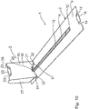
- the carriage 3 is placed in a first step on the top 7 of the bottom 5 of the rail 2, that the bottom wall 20 of the carriage 3 rests on the top 7 of the bottom 5 of the rail 2.
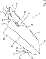
- the clamping means 4 which is provided in the present case as an annular rubber band, laid from above to the provided on the front end 10 of the bottom 5 projection 15, threaded from below through the positioned in the lower bottom layer 5a of the rail 2 through hole 12 through which provided in the upper bottom layer 5b of the bottom 5 of the rail 2 elongated passage opening 13 to the carriage 3, there threaded through the provided in the wall 18 through opening 21 and from below through the disposed in the bottom wall 20 of the carriage 3 through opening 25 and placed around the provided in the upper part of the wall 18 projection 22.
- the carriage 3 is pulled by the clamping means 4 in the direction of the front end face 10 of the bottom 5 of the rail 2.
- the lower bottom layer 5a and the upper bottom layer 5b of the rail 2 are pressed against each other by the tensioning means 4.
- the cloth feed system 1 can be arranged in a known manner in aêtumverpackung or in a display made of cardboard or corrugated cardboard (not shown) and then be stocked with goods.
- the top 7 of the Floor 5 arranged goods are then pressed by the carriage 3 in the direction of the front edge of the outer packaging or the display, so that the foremost goods comes to rest there. If goods are removed from the goods feed system 1, then the carriage 3 is automatically pulled forward by the tensioning means 4, so that the goods remaining in the goods advance system 1 are pushed forwards.
- the carriage 3 of the goods advance system 1 described above can also be arranged rotated by 180 ° on the rail 2.
- the clamping means 4 is then placed from above to the provided on the front end 10 of the bottom 5 of the rail 2 projection 15, threaded from below through the positioned in the lower bottom layer 5a of the rail 2 through hole 12, through in the upper Bottom layer 5b of the bottom 5 of the rail 2 provided elongated passage opening 13 to the carriage 3, threaded there from below through the arranged in the bottom wall 20 of the carriage 3 through opening 2, then passed through the provided in the wall 18 through opening 21 and finally from behind to laid in the upper region of the wall 18 provided projection 22.
- goods can additionally be positioned on the bottom wall 20 of the carriage 3 between the side walls 26 and 27, whereby the goods receiving capacity is increased.
- FIGS. 10 to 12 show a goods feed system 1 according to a second embodiment of the present invention or its components.
- the structure of this material feed system 1 basically corresponds to the structure of the previously described goods feed system 1.
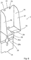
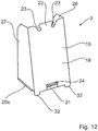
- a first difference is that in the in FIG. 10 shown goods feed system 1, the rail 2 and the carriage 3 locking means to temporarily lock the carriage 3 in its rear carriage position.
- the locking means are presently formed by two in the upper side 7 of the rail 2 in the region of the rear slide position, spaced from each other arranged locking recesses 31 and two of the bottom wall 20 of the carriage downwardly projecting locking projections 32 which can be brought into engagement with the locking recesses 31 selectively as it is in FIG. 10 is shown.
- the advantage of such locking means is that the goods feed system in the locked carriage position can be easily equipped with goods.
- the bottom wall 20 may be provided with latching recesses and the rail 2 with upwardly projecting latching projections from its upper side 7, even if this is not shown here.
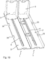
- FIGS. 13 to 18 show a goods feed system 1 according to a third embodiment of the present invention or its components.
- the structure of this cloth feed system basically corresponds to the structure of the cloth feed system 1 according to the first embodiment described above.
- a first difference is that the lower bottom layer 5a and the upper bottom layer 5b of the bottom 5 of the rail 2 are connected together along the front end face 10 of the bottom 5.
- the longitudinal sides 8 and 9 of the bottom 5 of the rail 2 are provided with connecting elements, which are designed to connect the bottoms 5 of the rails 2 laterally adjacent to each other Warrenvorschubsysteme 1 together, as in FIG. 19 is shown.
- the connecting elements are presently designed in the form of connecting projections 33 and connecting recesses 34 whose dimensions are adapted to each other and the form-fitting interlock.
- the rail 2 and the carriage 3 similarly as the cloth feed system 1 according to the second embodiment described above comprise locking means to temporarily lock the carriage 3 in its rear carriage position.
- locking means are presently formed by a single provided on the upper side 7 of the rail 2 locking recess 31 and a single protruding from the bottom wall 20 of the carriage 3 locking projection 32 which can engage the locking recess 31, as in FIG. 13 is shown.
- the latching recess 31 is T-shaped in the illustrated case, even if in principle other shapes are conceivable.
- the locking projection 32 is formed by a provided with a central opening for passing the clamping means 4 tab which is integrally formed on the front edge of the bottom wall 20 of the carriage 3 and bent downwards and to the rear.
- a slide platform 35 is formed on the rear end side of the rail 2, which in the present case consists of an upwardly and forwardly folded, parallel to the top 7 of the bottom 5 extending Podestlasche 36 which with a downwardly projecting retaining lug 37 in a bottom of the 5 Rail 2 provided retaining opening is fixed.
- the carriage platform 35 holds on the one hand the two bottom layers 5a and 5b of the bottom 5 of the rail 2 together.
- it takes on the carriage 3 in its rear carriage position and tilts its front portion down to press the locking projection 32 of the carriage 3 in the locking recess 31 of the rail 2, whereby a particularly good locking of the carriage 3 realized in the rear carriage position becomes.
- the carriage 3 For unlocking the carriage 3 must be pressed only slightly to the rear, so that the locking projection 32 is brought out of engagement with the locking recess 31. Yet another difference is that the carriage 3 is rotated by 180 ° compared to the embodiments described above, whereby more space is available for receiving goods, as additional goods between the side walls 27 and 27 of the carriage 3 can be arranged. In this arrangement of the carriage 3 can be dispensed with the passage opening 21 for passing the clamping means 4. Further smaller differences of the individual blanks of the rail 2 and the carriage 3 will become apparent from the drawing.
Landscapes
- Vending Machines For Individual Products (AREA)
- Cartons (AREA)
Priority Applications (1)
| Application Number | Priority Date | Filing Date | Title |
|---|---|---|---|
| EP18166691.8A EP3552524B1 (fr) | 2018-04-10 | 2018-04-10 | Distributeur pour d'avancement de la marchandises |
Applications Claiming Priority (1)
| Application Number | Priority Date | Filing Date | Title |
|---|---|---|---|
| EP18166691.8A EP3552524B1 (fr) | 2018-04-10 | 2018-04-10 | Distributeur pour d'avancement de la marchandises |
Publications (2)
| Publication Number | Publication Date |
|---|---|
| EP3552524A1 true EP3552524A1 (fr) | 2019-10-16 |
| EP3552524B1 EP3552524B1 (fr) | 2020-12-02 |
Family
ID=61965832
Family Applications (1)
| Application Number | Title | Priority Date | Filing Date |
|---|---|---|---|
| EP18166691.8A Active EP3552524B1 (fr) | 2018-04-10 | 2018-04-10 | Distributeur pour d'avancement de la marchandises |
Country Status (1)
| Country | Link |
|---|---|
| EP (1) | EP3552524B1 (fr) |
Citations (4)
| Publication number | Priority date | Publication date | Assignee | Title |
|---|---|---|---|---|
| FR2762502A1 (fr) * | 1997-04-29 | 1998-10-30 | Smurfit Socar Sa | Nouvelle barquette en un materiau semi-rigide, pour l'exposition en vente d'articles divers |
| DE102004015701B3 (de) | 2004-03-29 | 2005-07-21 | Thimm Verpackung Gmbh & Co. Kg | Verpackung für die abverkaufsgerechte Präsentation von Waren und Einsatz für eine Verkaufsverpackung |
| EP2949241A1 (fr) * | 2014-05-28 | 2015-12-02 | Werner Kenkel Sp. z o.o. | Plate-forme d'affichage |
| EP3176102A1 (fr) * | 2015-12-01 | 2017-06-07 | Saica Pack, S.L. | Plateau de présentation avec poignée intégrée |
-
2018
- 2018-04-10 EP EP18166691.8A patent/EP3552524B1/fr active Active
Patent Citations (4)
| Publication number | Priority date | Publication date | Assignee | Title |
|---|---|---|---|---|
| FR2762502A1 (fr) * | 1997-04-29 | 1998-10-30 | Smurfit Socar Sa | Nouvelle barquette en un materiau semi-rigide, pour l'exposition en vente d'articles divers |
| DE102004015701B3 (de) | 2004-03-29 | 2005-07-21 | Thimm Verpackung Gmbh & Co. Kg | Verpackung für die abverkaufsgerechte Präsentation von Waren und Einsatz für eine Verkaufsverpackung |
| EP2949241A1 (fr) * | 2014-05-28 | 2015-12-02 | Werner Kenkel Sp. z o.o. | Plate-forme d'affichage |
| EP3176102A1 (fr) * | 2015-12-01 | 2017-06-07 | Saica Pack, S.L. | Plateau de présentation avec poignée intégrée |
Also Published As
| Publication number | Publication date |
|---|---|
| EP3552524B1 (fr) | 2020-12-02 |
Similar Documents
| Publication | Publication Date | Title |
|---|---|---|
| DE2633972C3 (de) | Anordnung zum Verbinden zweier Bauteile | |
| EP3094568B1 (fr) | Contenant pour le transport de marchandises et dispositif pour compartimenter un tel contenant | |
| DE29609483U1 (de) | Gestell zur Aufbewahrung von Werkzeugen | |
| DE2830676C2 (de) | Skihaltevorrichtung | |
| DE7727438U1 (de) | Aufbewahrungskasten fuer sortiert aufzubewahrende kleinteile | |
| DE4417857C2 (de) | Fixiervorrichtung zur variablen Festlegung von Ladegut | |
| DE19710515C1 (de) | Steckkarte für elektronische Geräte | |
| DE102017128562A1 (de) | Regalbox mit Arretieranschlägen | |
| EP3552524B1 (fr) | Distributeur pour d'avancement de la marchandises | |
| DE3509989C2 (fr) | ||
| EP2767483A2 (fr) | Récipient de transport empilable | |
| DE102019122722B3 (de) | Display | |
| DE2928118C2 (de) | Zur nebeneinander gereihten Befestigung an einer Montageschiene ausgebildetes Schalttafelelement, insbesondere Sicherungsautomat oder Trennschalter | |
| DE9108211U1 (de) | Modulare Kunststoffklappe | |
| DE19944654A1 (de) | Montageeinheit | |
| EP3623219B1 (fr) | Profil de sécurité de chargement ainsi que surface de chargement permettant de recevoir une cargaison transportée | |
| DE202017107337U1 (de) | Regalbox mit Arretieranschlägen | |
| EP0185201A1 (fr) | Tiroir en matière plastique | |
| DE3500542A1 (de) | Steckteiler-fachunterteilung von schubladen o.dgl. | |
| DE102011101281B3 (de) | Verriegelungsvorrichtung | |
| DE9105237U1 (de) | Blechschubkasten | |
| AT398515B (de) | Beschlag zur lösbaren halterung | |
| DE202005009774U1 (de) | Faltkiste | |
| DE3324553A1 (de) | Transport- und/oder display-einheit | |
| DE202023105372U1 (de) | Haltevorrichtung zur Anbringung eines Einsatzteils an einem Regalpfosten |
Legal Events
| Date | Code | Title | Description |
|---|---|---|---|
| PUAI | Public reference made under article 153(3) epc to a published international application that has entered the european phase |
Free format text: ORIGINAL CODE: 0009012 |
|
| STAA | Information on the status of an ep patent application or granted ep patent |
Free format text: STATUS: THE APPLICATION HAS BEEN PUBLISHED |
|
| AK | Designated contracting states |
Kind code of ref document: A1 Designated state(s): AL AT BE BG CH CY CZ DE DK EE ES FI FR GB GR HR HU IE IS IT LI LT LU LV MC MK MT NL NO PL PT RO RS SE SI SK SM TR |
|
| AX | Request for extension of the european patent |
Extension state: BA ME |
|
| STAA | Information on the status of an ep patent application or granted ep patent |
Free format text: STATUS: REQUEST FOR EXAMINATION WAS MADE |
|
| 17P | Request for examination filed |
Effective date: 20191112 |
|
| RBV | Designated contracting states (corrected) |
Designated state(s): AL AT BE BG CH CY CZ DE DK EE ES FI FR GB GR HR HU IE IS IT LI LT LU LV MC MK MT NL NO PL PT RO RS SE SI SK SM TR |
|
| STAA | Information on the status of an ep patent application or granted ep patent |
Free format text: STATUS: EXAMINATION IS IN PROGRESS |
|
| 17Q | First examination report despatched |
Effective date: 20200408 |
|
| GRAP | Despatch of communication of intention to grant a patent |
Free format text: ORIGINAL CODE: EPIDOSNIGR1 |
|
| STAA | Information on the status of an ep patent application or granted ep patent |
Free format text: STATUS: GRANT OF PATENT IS INTENDED |
|
| INTG | Intention to grant announced |
Effective date: 20200827 |
|
| GRAS | Grant fee paid |
Free format text: ORIGINAL CODE: EPIDOSNIGR3 |
|
| GRAA | (expected) grant |
Free format text: ORIGINAL CODE: 0009210 |
|
| STAA | Information on the status of an ep patent application or granted ep patent |
Free format text: STATUS: THE PATENT HAS BEEN GRANTED |
|
| AK | Designated contracting states |
Kind code of ref document: B1 Designated state(s): AL AT BE BG CH CY CZ DE DK EE ES FI FR GB GR HR HU IE IS IT LI LT LU LV MC MK MT NL NO PL PT RO RS SE SI SK SM TR |
|
| REG | Reference to a national code |
Ref country code: GB Ref legal event code: FG4D Free format text: NOT ENGLISH |
|
| REG | Reference to a national code |
Ref country code: AT Ref legal event code: REF Ref document number: 1339944 Country of ref document: AT Kind code of ref document: T Effective date: 20201215 Ref country code: CH Ref legal event code: EP |
|
| REG | Reference to a national code |
Ref country code: IE Ref legal event code: FG4D Free format text: LANGUAGE OF EP DOCUMENT: GERMAN |
|
| REG | Reference to a national code |
Ref country code: DE Ref legal event code: R096 Ref document number: 502018003151 Country of ref document: DE |
|
| REG | Reference to a national code |
Ref country code: NL Ref legal event code: FP |
|
| PG25 | Lapsed in a contracting state [announced via postgrant information from national office to epo] |
Ref country code: FI Free format text: LAPSE BECAUSE OF FAILURE TO SUBMIT A TRANSLATION OF THE DESCRIPTION OR TO PAY THE FEE WITHIN THE PRESCRIBED TIME-LIMIT Effective date: 20201202 Ref country code: RS Free format text: LAPSE BECAUSE OF FAILURE TO SUBMIT A TRANSLATION OF THE DESCRIPTION OR TO PAY THE FEE WITHIN THE PRESCRIBED TIME-LIMIT Effective date: 20201202 Ref country code: NO Free format text: LAPSE BECAUSE OF FAILURE TO SUBMIT A TRANSLATION OF THE DESCRIPTION OR TO PAY THE FEE WITHIN THE PRESCRIBED TIME-LIMIT Effective date: 20210302 Ref country code: GR Free format text: LAPSE BECAUSE OF FAILURE TO SUBMIT A TRANSLATION OF THE DESCRIPTION OR TO PAY THE FEE WITHIN THE PRESCRIBED TIME-LIMIT Effective date: 20210303 |
|
| PG25 | Lapsed in a contracting state [announced via postgrant information from national office to epo] |
Ref country code: SE Free format text: LAPSE BECAUSE OF FAILURE TO SUBMIT A TRANSLATION OF THE DESCRIPTION OR TO PAY THE FEE WITHIN THE PRESCRIBED TIME-LIMIT Effective date: 20201202 Ref country code: BG Free format text: LAPSE BECAUSE OF FAILURE TO SUBMIT A TRANSLATION OF THE DESCRIPTION OR TO PAY THE FEE WITHIN THE PRESCRIBED TIME-LIMIT Effective date: 20210302 Ref country code: PL Free format text: LAPSE BECAUSE OF FAILURE TO SUBMIT A TRANSLATION OF THE DESCRIPTION OR TO PAY THE FEE WITHIN THE PRESCRIBED TIME-LIMIT Effective date: 20201202 Ref country code: LV Free format text: LAPSE BECAUSE OF FAILURE TO SUBMIT A TRANSLATION OF THE DESCRIPTION OR TO PAY THE FEE WITHIN THE PRESCRIBED TIME-LIMIT Effective date: 20201202 |
|
| PG25 | Lapsed in a contracting state [announced via postgrant information from national office to epo] |
Ref country code: HR Free format text: LAPSE BECAUSE OF FAILURE TO SUBMIT A TRANSLATION OF THE DESCRIPTION OR TO PAY THE FEE WITHIN THE PRESCRIBED TIME-LIMIT Effective date: 20201202 |
|
| REG | Reference to a national code |
Ref country code: LT Ref legal event code: MG9D |
|
| PG25 | Lapsed in a contracting state [announced via postgrant information from national office to epo] |
Ref country code: CZ Free format text: LAPSE BECAUSE OF FAILURE TO SUBMIT A TRANSLATION OF THE DESCRIPTION OR TO PAY THE FEE WITHIN THE PRESCRIBED TIME-LIMIT Effective date: 20201202 Ref country code: EE Free format text: LAPSE BECAUSE OF FAILURE TO SUBMIT A TRANSLATION OF THE DESCRIPTION OR TO PAY THE FEE WITHIN THE PRESCRIBED TIME-LIMIT Effective date: 20201202 Ref country code: SM Free format text: LAPSE BECAUSE OF FAILURE TO SUBMIT A TRANSLATION OF THE DESCRIPTION OR TO PAY THE FEE WITHIN THE PRESCRIBED TIME-LIMIT Effective date: 20201202 Ref country code: LT Free format text: LAPSE BECAUSE OF FAILURE TO SUBMIT A TRANSLATION OF THE DESCRIPTION OR TO PAY THE FEE WITHIN THE PRESCRIBED TIME-LIMIT Effective date: 20201202 Ref country code: RO Free format text: LAPSE BECAUSE OF FAILURE TO SUBMIT A TRANSLATION OF THE DESCRIPTION OR TO PAY THE FEE WITHIN THE PRESCRIBED TIME-LIMIT Effective date: 20201202 Ref country code: SK Free format text: LAPSE BECAUSE OF FAILURE TO SUBMIT A TRANSLATION OF THE DESCRIPTION OR TO PAY THE FEE WITHIN THE PRESCRIBED TIME-LIMIT Effective date: 20201202 Ref country code: PT Free format text: LAPSE BECAUSE OF FAILURE TO SUBMIT A TRANSLATION OF THE DESCRIPTION OR TO PAY THE FEE WITHIN THE PRESCRIBED TIME-LIMIT Effective date: 20210405 |
|
| REG | Reference to a national code |
Ref country code: DE Ref legal event code: R097 Ref document number: 502018003151 Country of ref document: DE |
|
| PG25 | Lapsed in a contracting state [announced via postgrant information from national office to epo] |
Ref country code: IS Free format text: LAPSE BECAUSE OF FAILURE TO SUBMIT A TRANSLATION OF THE DESCRIPTION OR TO PAY THE FEE WITHIN THE PRESCRIBED TIME-LIMIT Effective date: 20210402 |
|
| PLBE | No opposition filed within time limit |
Free format text: ORIGINAL CODE: 0009261 |
|
| STAA | Information on the status of an ep patent application or granted ep patent |
Free format text: STATUS: NO OPPOSITION FILED WITHIN TIME LIMIT |
|
| PG25 | Lapsed in a contracting state [announced via postgrant information from national office to epo] |
Ref country code: IT Free format text: LAPSE BECAUSE OF FAILURE TO SUBMIT A TRANSLATION OF THE DESCRIPTION OR TO PAY THE FEE WITHIN THE PRESCRIBED TIME-LIMIT Effective date: 20201202 Ref country code: AL Free format text: LAPSE BECAUSE OF FAILURE TO SUBMIT A TRANSLATION OF THE DESCRIPTION OR TO PAY THE FEE WITHIN THE PRESCRIBED TIME-LIMIT Effective date: 20201202 |
|
| 26N | No opposition filed |
Effective date: 20210903 |
|
| PG25 | Lapsed in a contracting state [announced via postgrant information from national office to epo] |
Ref country code: DK Free format text: LAPSE BECAUSE OF FAILURE TO SUBMIT A TRANSLATION OF THE DESCRIPTION OR TO PAY THE FEE WITHIN THE PRESCRIBED TIME-LIMIT Effective date: 20201202 Ref country code: SI Free format text: LAPSE BECAUSE OF FAILURE TO SUBMIT A TRANSLATION OF THE DESCRIPTION OR TO PAY THE FEE WITHIN THE PRESCRIBED TIME-LIMIT Effective date: 20201202 |
|
| PG25 | Lapsed in a contracting state [announced via postgrant information from national office to epo] |
Ref country code: ES Free format text: LAPSE BECAUSE OF FAILURE TO SUBMIT A TRANSLATION OF THE DESCRIPTION OR TO PAY THE FEE WITHIN THE PRESCRIBED TIME-LIMIT Effective date: 20201202 |
|
| PG25 | Lapsed in a contracting state [announced via postgrant information from national office to epo] |
Ref country code: IE Free format text: LAPSE BECAUSE OF NON-PAYMENT OF DUE FEES Effective date: 20210410 |
|
| PG25 | Lapsed in a contracting state [announced via postgrant information from national office to epo] |
Ref country code: IS Free format text: LAPSE BECAUSE OF FAILURE TO SUBMIT A TRANSLATION OF THE DESCRIPTION OR TO PAY THE FEE WITHIN THE PRESCRIBED TIME-LIMIT Effective date: 20210402 |
|
| GBPC | Gb: european patent ceased through non-payment of renewal fee |
Effective date: 20220410 |
|
| PG25 | Lapsed in a contracting state [announced via postgrant information from national office to epo] |
Ref country code: GB Free format text: LAPSE BECAUSE OF NON-PAYMENT OF DUE FEES Effective date: 20220410 |
|
| P01 | Opt-out of the competence of the unified patent court (upc) registered |
Effective date: 20230331 |
|
| P02 | Opt-out of the competence of the unified patent court (upc) changed |
Effective date: 20230403 |
|
| PG25 | Lapsed in a contracting state [announced via postgrant information from national office to epo] |
Ref country code: CY Free format text: LAPSE BECAUSE OF FAILURE TO SUBMIT A TRANSLATION OF THE DESCRIPTION OR TO PAY THE FEE WITHIN THE PRESCRIBED TIME-LIMIT Effective date: 20201202 |
|
| P02 | Opt-out of the competence of the unified patent court (upc) changed |
Effective date: 20230525 |
|
| PG25 | Lapsed in a contracting state [announced via postgrant information from national office to epo] |
Ref country code: HU Free format text: LAPSE BECAUSE OF FAILURE TO SUBMIT A TRANSLATION OF THE DESCRIPTION OR TO PAY THE FEE WITHIN THE PRESCRIBED TIME-LIMIT; INVALID AB INITIO Effective date: 20180410 |
|
| PG25 | Lapsed in a contracting state [announced via postgrant information from national office to epo] |
Ref country code: MK Free format text: LAPSE BECAUSE OF FAILURE TO SUBMIT A TRANSLATION OF THE DESCRIPTION OR TO PAY THE FEE WITHIN THE PRESCRIBED TIME-LIMIT Effective date: 20201202 |
|
| PG25 | Lapsed in a contracting state [announced via postgrant information from national office to epo] |
Ref country code: TR Free format text: LAPSE BECAUSE OF FAILURE TO SUBMIT A TRANSLATION OF THE DESCRIPTION OR TO PAY THE FEE WITHIN THE PRESCRIBED TIME-LIMIT Effective date: 20201202 |
|
| PG25 | Lapsed in a contracting state [announced via postgrant information from national office to epo] |
Ref country code: MT Free format text: LAPSE BECAUSE OF FAILURE TO SUBMIT A TRANSLATION OF THE DESCRIPTION OR TO PAY THE FEE WITHIN THE PRESCRIBED TIME-LIMIT Effective date: 20201202 |
|
| PGFP | Annual fee paid to national office [announced via postgrant information from national office to epo] |
Ref country code: NL Payment date: 20250402 Year of fee payment: 8 |
|
| PGFP | Annual fee paid to national office [announced via postgrant information from national office to epo] |
Ref country code: LU Payment date: 20250417 Year of fee payment: 8 |
|
| PGFP | Annual fee paid to national office [announced via postgrant information from national office to epo] |
Ref country code: DE Payment date: 20250312 Year of fee payment: 8 |
|
| PGFP | Annual fee paid to national office [announced via postgrant information from national office to epo] |
Ref country code: CH Payment date: 20250501 Year of fee payment: 8 |
|
| PGFP | Annual fee paid to national office [announced via postgrant information from national office to epo] |
Ref country code: AT Payment date: 20250402 Year of fee payment: 8 |
|
| PGFP | Annual fee paid to national office [announced via postgrant information from national office to epo] |
Ref country code: MC Payment date: 20260327 Year of fee payment: 9 |
|
| PGFP | Annual fee paid to national office [announced via postgrant information from national office to epo] |
Ref country code: BE Payment date: 20260211 Year of fee payment: 9 |
|
| PGFP | Annual fee paid to national office [announced via postgrant information from national office to epo] |
Ref country code: FR Payment date: 20260226 Year of fee payment: 9 |