EP3551906B1 - Disque de frein ventilé - Google Patents
Disque de frein ventilé Download PDFInfo
- Publication number
- EP3551906B1 EP3551906B1 EP17880482.9A EP17880482A EP3551906B1 EP 3551906 B1 EP3551906 B1 EP 3551906B1 EP 17880482 A EP17880482 A EP 17880482A EP 3551906 B1 EP3551906 B1 EP 3551906B1
- Authority
- EP
- European Patent Office
- Prior art keywords
- segment
- hub
- segments
- brake disc
- brake
- Prior art date
- Legal status (The legal status is an assumption and is not a legal conclusion. Google has not performed a legal analysis and makes no representation as to the accuracy of the status listed.)
- Active
Links
Images


Classifications
-
- F—MECHANICAL ENGINEERING; LIGHTING; HEATING; WEAPONS; BLASTING
- F16—ENGINEERING ELEMENTS AND UNITS; GENERAL MEASURES FOR PRODUCING AND MAINTAINING EFFECTIVE FUNCTIONING OF MACHINES OR INSTALLATIONS; THERMAL INSULATION IN GENERAL
- F16D—COUPLINGS FOR TRANSMITTING ROTATION; CLUTCHES; BRAKES
- F16D65/00—Parts or details
- F16D65/02—Braking members; Mounting thereof
- F16D65/12—Discs; Drums for disc brakes
- F16D65/128—Discs; Drums for disc brakes characterised by means for cooling
-
- F—MECHANICAL ENGINEERING; LIGHTING; HEATING; WEAPONS; BLASTING
- F16—ENGINEERING ELEMENTS AND UNITS; GENERAL MEASURES FOR PRODUCING AND MAINTAINING EFFECTIVE FUNCTIONING OF MACHINES OR INSTALLATIONS; THERMAL INSULATION IN GENERAL
- F16D—COUPLINGS FOR TRANSMITTING ROTATION; CLUTCHES; BRAKES
- F16D65/00—Parts or details
- F16D65/78—Features relating to cooling
- F16D65/84—Features relating to cooling for disc brakes
- F16D65/847—Features relating to cooling for disc brakes with open cooling system, e.g. cooled by air
-
- F—MECHANICAL ENGINEERING; LIGHTING; HEATING; WEAPONS; BLASTING
- F16—ENGINEERING ELEMENTS AND UNITS; GENERAL MEASURES FOR PRODUCING AND MAINTAINING EFFECTIVE FUNCTIONING OF MACHINES OR INSTALLATIONS; THERMAL INSULATION IN GENERAL
- F16D—COUPLINGS FOR TRANSMITTING ROTATION; CLUTCHES; BRAKES
- F16D65/00—Parts or details
- F16D65/02—Braking members; Mounting thereof
- F16D65/12—Discs; Drums for disc brakes
- F16D65/123—Discs; Drums for disc brakes comprising an annular disc secured to a hub member; Discs characterised by means for mounting
-
- F—MECHANICAL ENGINEERING; LIGHTING; HEATING; WEAPONS; BLASTING
- F16—ENGINEERING ELEMENTS AND UNITS; GENERAL MEASURES FOR PRODUCING AND MAINTAINING EFFECTIVE FUNCTIONING OF MACHINES OR INSTALLATIONS; THERMAL INSULATION IN GENERAL
- F16D—COUPLINGS FOR TRANSMITTING ROTATION; CLUTCHES; BRAKES
- F16D65/00—Parts or details
- F16D65/02—Braking members; Mounting thereof
- F16D2065/13—Parts or details of discs or drums
- F16D2065/1304—Structure
- F16D2065/1312—Structure circumferentially segmented
-
- F—MECHANICAL ENGINEERING; LIGHTING; HEATING; WEAPONS; BLASTING
- F16—ENGINEERING ELEMENTS AND UNITS; GENERAL MEASURES FOR PRODUCING AND MAINTAINING EFFECTIVE FUNCTIONING OF MACHINES OR INSTALLATIONS; THERMAL INSULATION IN GENERAL
- F16D—COUPLINGS FOR TRANSMITTING ROTATION; CLUTCHES; BRAKES
- F16D65/00—Parts or details
- F16D65/02—Braking members; Mounting thereof
- F16D2065/13—Parts or details of discs or drums
- F16D2065/1304—Structure
- F16D2065/1316—Structure radially segmented
-
- F—MECHANICAL ENGINEERING; LIGHTING; HEATING; WEAPONS; BLASTING
- F16—ENGINEERING ELEMENTS AND UNITS; GENERAL MEASURES FOR PRODUCING AND MAINTAINING EFFECTIVE FUNCTIONING OF MACHINES OR INSTALLATIONS; THERMAL INSULATION IN GENERAL
- F16D—COUPLINGS FOR TRANSMITTING ROTATION; CLUTCHES; BRAKES
- F16D65/00—Parts or details
- F16D65/02—Braking members; Mounting thereof
- F16D2065/13—Parts or details of discs or drums
- F16D2065/1304—Structure
- F16D2065/1328—Structure internal cavities, e.g. cooling channels
-
- F—MECHANICAL ENGINEERING; LIGHTING; HEATING; WEAPONS; BLASTING
- F16—ENGINEERING ELEMENTS AND UNITS; GENERAL MEASURES FOR PRODUCING AND MAINTAINING EFFECTIVE FUNCTIONING OF MACHINES OR INSTALLATIONS; THERMAL INSULATION IN GENERAL
- F16D—COUPLINGS FOR TRANSMITTING ROTATION; CLUTCHES; BRAKES
- F16D65/00—Parts or details
- F16D65/02—Braking members; Mounting thereof
- F16D2065/13—Parts or details of discs or drums
- F16D2065/134—Connection
- F16D2065/1384—Connection to wheel hub
-
- F—MECHANICAL ENGINEERING; LIGHTING; HEATING; WEAPONS; BLASTING
- F16—ENGINEERING ELEMENTS AND UNITS; GENERAL MEASURES FOR PRODUCING AND MAINTAINING EFFECTIVE FUNCTIONING OF MACHINES OR INSTALLATIONS; THERMAL INSULATION IN GENERAL
- F16D—COUPLINGS FOR TRANSMITTING ROTATION; CLUTCHES; BRAKES
- F16D65/00—Parts or details
- F16D65/02—Braking members; Mounting thereof
- F16D2065/13—Parts or details of discs or drums
- F16D2065/134—Connection
- F16D2065/1388—Connection to shaft or axle
-
- F—MECHANICAL ENGINEERING; LIGHTING; HEATING; WEAPONS; BLASTING
- F16—ENGINEERING ELEMENTS AND UNITS; GENERAL MEASURES FOR PRODUCING AND MAINTAINING EFFECTIVE FUNCTIONING OF MACHINES OR INSTALLATIONS; THERMAL INSULATION IN GENERAL
- F16D—COUPLINGS FOR TRANSMITTING ROTATION; CLUTCHES; BRAKES
- F16D65/00—Parts or details
- F16D65/02—Braking members; Mounting thereof
- F16D2065/13—Parts or details of discs or drums
- F16D2065/134—Connection
- F16D2065/1392—Connection elements
-
- F—MECHANICAL ENGINEERING; LIGHTING; HEATING; WEAPONS; BLASTING
- F16—ENGINEERING ELEMENTS AND UNITS; GENERAL MEASURES FOR PRODUCING AND MAINTAINING EFFECTIVE FUNCTIONING OF MACHINES OR INSTALLATIONS; THERMAL INSULATION IN GENERAL
- F16D—COUPLINGS FOR TRANSMITTING ROTATION; CLUTCHES; BRAKES
- F16D65/00—Parts or details
- F16D65/02—Braking members; Mounting thereof
- F16D65/12—Discs; Drums for disc brakes
- F16D65/121—Discs; Drums for disc brakes consisting of at least three circumferentially arranged segments
Definitions
- the present invention relates to a friction ring, a brake assembly, and a brake disc for a rotating body, such as a wheel. More specifically, the brake disc relates to an annular brake disc with a ventilating structure for directing airflow across at least a portion of the disc to transfer heat therefrom.
- Brake discs are affixed to wheels or rotors for the purpose of providing a smooth, hard contact surface that can be contacted by a brake shoe or pad controlled by a brake mechanism, such as a brake jaw. When contact between the disc and shoe or pad is established, friction between the elements is sufficient to slow or stop rotation of the wheel.
- Disc brakes are commonly used in a variety of applications including, for example, industrial machines, such as cranes and lifts, as well as in conveying installations, such as escalators, elevators, ski-lifts, and the like.
- Disc brake assemblies are also employed in transport vehicles, such as rail cars, public transportation vehicles, trucks, and automobiles.
- United States Patent No. 4,132,294 to Poli entitled “Braking disc with replaceable linings, for brake-discs” (“the ⁇ 294 patent”) discloses an annular brake disc including radial fins or gills for directing airflow between front and rear brake discs of a brake assembly.
- the front and rear brake discs include openings on the disc surface located near the central portion of the wheel or wheel hub. Air is drawn into the openings and directed radially outward along the inner surface of the brake discs by the fins or gills. Heat created by the brake disc is transferred to the fins or gills and ventilated by the airflow. In this way, the fins or gills remove heat from the brake disc and wheel to improve performance thereof.
- a brake assembly Thermal expansion and degradation of a brake assembly is also addressed by the shape of the disc itself. More specifically, to make the brake linings and/or brake discs more accessible and to simplify maintenance, brake discs have been developed that are formed from two or more interlocking segments or friction rings, which can be individually removed and replaced. For example, the '294 patent discloses a disc brake including two or more linings disposed about a central hub.
- segmented disc brakes are known in which individual segments are spaced apart by a gap to permit the segments to expand when exposed to heat.
- United States Patent No. 5,788,026 to Poli entitled "Brake disc assembly for a rotational body” discloses a disc brake having a number of brake disc segments affixed to a rotating body to form an annular ring. Corresponding segments of the disc brake are attached to one another by fasteners extending through-holes in the segments and rotating body. The segments are also slidably connected to adjacent segments in the annular disc brake by joining elements or pins extending from a socket of a segment to a corresponding socket of the adjacent segment.
- United States Patent No. 4,132,294 entitled “Braking disc with replaceable linings, for brake discs”, discloses a braking disc comprising two annular linings on which the braking jaws are active, the latter being applied to a central driving hub mounted on the shaft to be braked.
- German Patent Application Publication No. DE19507922 entitled “Compound ventilated braking disc” discloses a composite internally ventilated brake disc for vehicle disc brakes, in particular rail vehicles, with a hub and friction rings attached to it.
- United States Patent Application Publication No. US2016/0076613 entitled “Brake disc assembly for a wheel”, discloses a brake disc for a rotating member, such as a wheel, and an annular brake disc formed from a plurality of interconnected brake disc segments.
- airflow volume and speed across the disc should be maximized to increase the cooling effect.
- the airflow pattern should be improved so that airflow is made available to portions of the disc that are most likely to be exposed to substantial heat.
- the brake disc disclosed herein is designed for such optimized and improved airflow.
- the brake assembly of the present invention provides a friction ring or brake disc that connects to a wheel, rotor, or hub and ventilates heat from the brake disc by directing airflow radially outward along an inner surface of the disc.
- the structure of the brake disc including radial protrusions or fins and placement of through-holes and fasteners, is designed to maximize ventilation through the disc.
- the present inventor recognized that through specific placement of the through-hole and fin structures, airflow between the disc and hub is effectively maximized. As a result of such airflow, damage from thermal stress and thermal expansion of the disc is effectively reduced. Accordingly, the brake disc assembly is less susceptible to wear-based damage and operates more quietly than known alternative systems.
- this invention is directed to a brake assembly configured to be connected to a hub or axel of a rotating body.
- the assembly addresses or overcomes some or all of the deficiencies and drawbacks associated with existing braking systems.
- a friction ring according to claim 1 is provided.
- a brake assembly according to claim 13 is provided.
- a brake disc according to claim 10 is provided.
- the present invention is directed to a friction ring or brake disc for a rotating body or wheel structure, such as a railway vehicle wheel.
- the friction ring or brake disc may be a unitary structure (e.g., a monobloc disc) or segmented, as illustrated in the accompanying figures.
- the brake disc may be used to restrict rotation of railway vehicle wheels and, specifically, for low speed rail vehicles having a speed of less than 200 km/hr.
- a brake disc refers to a structure adapted to connect to a rotating body and configured to be contacted by a braking mechanism, such as a brake jaw, brake pad, or brake shoe. Friction between the brake disc and shoe slows or stops rotation of the rotating body.
- Brake discs are generally either hub mounted or wheel mounted. Hub mounted brake discs (also referred to as an axle mounted disc) are connected to the hub or axle of the rotating body. In contrast, wheel mounted brake discs are connected directly to a surface of the wheel itself rather than to the hub or axle.
- the brake disc is configured to be fixed to the hub with the minimum number of fixation points allowed by safety calculations.
- Safety calculations can include computer modeling techniques for modeling forces exerted on the disc during use. Determining the minimum number of fixation points can consider, for example, the number of fixation points needed to form a stable and sufficiently strong connection between the brake disc and hub to ensure sufficient stopping power during use.
- each segment may be mounted to the hub at a single fixation point. The segment may be permitted to rotate about the single fixation point. Mounting the segment and/or disc to the hub at a minimum number of fixation points allows for creation of a disc with a maximized air inlet area, thereby providing maximum air flux across an inner surface of the brake disc and a highest possible ventilation.
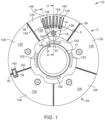
- the assembly 10 includes a hub 12 with a radial flange 14 extending therefrom.
- the hub 12 may be configured to receive a rotating body, such as an axle of a railway vehicle or similar rotating structure.
- the flange 14 includes a front side surface 18 and a rear side surface 20 (shown in FIGS. 2 and 3 ).
- the flange 14 may be the same thickness throughout or may include regions having a different thicknesses or rigidity.
- the flange 14 may include alternating concentric bands (not shown) having high and low rigidity. The rigidity of the various regions may result from varying either the thickness or material composition of the flange 14.
- the assembly 10 further comprises a friction ring or brake disc 2 having a front side 24 connected to the front side surface 18 of the flange 14 and a rear side 24' (shown in FIGS. 2 and 3 ) connected to the rear side surface 20.
- a friction ring or brake disc 2 having a front side 24 connected to the front side surface 18 of the flange 14 and a rear side 24' (shown in FIGS. 2 and 3 ) connected to the rear side surface 20.
- a friction ring or brake disc 2 having a front side 24 connected to the front side surface 18 of the flange 14 and a rear side 24' (shown in FIGS. 2 and 3 ) connected to the rear side surface 20.
- the rear side 24' has a similar or identical structure as the front side 24 and, therefore, includes the features described hereinafter.
- the brake disc 2 is a segmented disc formed from a plurality of segments 126.
- the disc 2 can be formed from five substantially identically shaped segments. While a segmented brake disc 2 is described and illustrated herein, it is understood that the brake disc may also be a ring-shaped monobloc structure within the scope of the present invention.
- the segments 126 may be connected around the hub 12 to form a closed annular ring. The closed ring may be referred to as a friction ring.
- the segments 126 illustrated in FIG. 1 are the same size and shape, it is understood that the brake disc 2 may include segments having different shapes and sizes. The total number of segments may be even or odd.
- the segments 126 may be separated from one another by a radial gap 36 between the radial ends 142 of adjacent segments 126 so that the segments 126 can freely expand or contract depending on the temperature and force applied by the brake shoe or pad.
- the segments 126 are connected together by joining elements 38 extending across the gap 36.
- each segment 126 is connected to the adjacent segment 126 by one joining element 38 located near the outer circumferential side 144 of the segment 126.
- the brake disc 24 may include multiple joining elements 38 between each segment 126.
- the assembly 10 could include two joining elements 38 between each segment 126.
- the joining elements 38 may be positioned at equidistant positions from the central axis X of the segment 126.
- the joining element 38 may be a pin, fastener, or slider as is known in the art.
- the joining elements 38 are configured to be inserted in a socket 140 extending inward from the radial end 142 of each segment 126, such that each joining element 38 extends between corresponding sockets 140 of adjacent segments 126.
- the depth of each socket 140 is greater than the length of the associated joining element 38. Accordingly, the segments 126 are free to move, relative to the joining elements 38, causing the joining element 38 to insert farther into one segment 126 and to pull away from the adjacent segment 126.
- each side 24, 24' of each segment 126 comprises an outer surface 128, which functions as a standard braking surface.
- the outer surface 128 provides a substantially flat surface or face that is configured to be contacted by a brake surface, such as a brake shoe or pad controlled by a braking mechanism.
- the surface 128 may include regions that have been treated or machined to increase texture, hardness, or durability thereof to improve contact and, if necessary, to increase friction between the outer surface 128 and braking mechanism.
- Each side 24, 24' of each segment 126 also includes an inner surface 130 opposite the outer surface 128. A portion of the inner surface 130 is configured to contact the front side surface 18 and flange 14 to provide a stopping force F thereto when the brake assembly 10 is in use.
- the inner surface 130 of the segment 126 may include a thicker or wider portion 132 that physically contacts the front side surface 18 of the flange 14.
- the segment has a generally tapered appearance that is thicker adjacent to the hub 12 and thinner near the outer circumferential side 144 of the segment 126.
- the segments 126 may further comprise protrusions extending between the inner surfaces 130 of the front side 24 and the rear side 24' each segment 126.
- the protrusions comprise radially extending fins.
- the protrusions may comprise ribs, baffles, columns, walls, or any combination thereof.
- the protrusions may be integrally formed with the inner surface 130 of the segment 126 or attached thereto using a known adhesive or fastener.
- the protrusions are arranged to direct a cooling airflow C (shown in FIG.
- the front side 24 and the rear side 24' of the segments 126 are separated.
- the protrusions include contact surfaces that contact the surface of the wheel or rotating body.
- the sides 24, 24' are separated or divided in this manner, they are free to slide or move relative to one another.
- thermal expansion of the segments 126 is not restricted.
- thermal stresses caused by expansion are not translated between opposing segments 126, reducing the possibility that the protrusions will be damaged during use.
- the protrusions may be radial fins 135 having a long, thin structure with substantially flat opposing faces.
- the fins 135 are positioned to maximize ventilation through the brake disc assembly 10. Maximizing ventilation enhances cooling of the brake disc segments 126.
- the fins 135 may have a substantially rectangular or elliptical base area that contacts the inner surface 130 of the segment 126.
- the fins 135 may extend radially outwardly along the inner surface 130 of the segment 126 from the inner circumferential edge 146 thereof to the outer circumferential edge 144.
- the fins 135 may be tapered, becoming narrower as the distance from the inner surface(s) 130 increases.
- the fins 135 may also be wider near the inner circumferential side 146 of the segment 126 and narrower near the outer circumferential side 144, such that the distance between adjacent fins 135 increases farther away from the hub 12.
- the fins 135 extend radially outward from the inner circumferential side 146 directly along a radius of the segment 126.
- the fins 135 may be positioned elsewhere on the inner surface 130 of the segment 126 to obtain various airflow patterns.
- some of the fins 135 may be positioned such that a central axis of the fin 135 is angled (for example by at least 5 degrees) relative to the radius of the segment 126. In this orientation, distances between adjacent fins 135 increases substantially radially outward from the hub 12.
- a central axis of each fin 135 may be parallel to a central axis of adjacent fins.
- the fins 135 may also be different lengths, such that fins 135 located near the radial ends 142 of the segment 126 are longer than fins 135 near the center of the segment 126. As will be described hereinafter, having fins 135 with different lengths allows for various connection structures to be included on the inner surface 130 of the segment 126 for connecting the segment 126 to other segments 126 and/or to the hub 12 (shown in FIGS. 2 and 3 ).
- the fins 135 are positioned to define channels 150 between adjacent fins 135.
- the channels 150 are radially extending channels 150 as shown in FIGS. 1-4 .
- the channels 150 are enclosed by the radially extending sides of the fins 135, the inner surfaces 130 of the opposing sides 24, 24' of the segments 126, and the front and rear sides 18, 20 of the flange 14.
- External cool air enters the channels 150 through an inlet portion 152, located between the inner circumferential side 146 of the segment 126 and the hub 12, and passes through the channels 150 along cooling airflow C (shown in FIGS. 3 and 4 ).
- the air is expelled from the channels 150 through outlet portions 154 located near the outer circumferential side 144 of the segments 126.
- the inlet portion 152 may be an annular opening extending around the hub 12. Alternatively, in certain embodiments, the inlet portion(s) 152 may be a number of distinct holes, slots, or openings located around the hub 12.
- the outlet portion 154 may also be an annular opening, a partially annular opening, a slot, or a number of holes arranged around the outer circumferential side 144 of the segments 126. In each case, however, the cross-sectional area of the inlet portion 152, even if maximized, is less than the cross-sectional area of the outlet portion 154. Thus, the cross section area of the channels 150 increases farther away from the center of the disc 24.
- the increase in cross-sectional area between the inlet portion 152 and the outlet portion 154 causes the airflow rate or air speed to increase along the length of the channel 150.
- the increased air speed improves ventilation and cooling of the segment 126.
- the width of the channels 150 increases along its length, such that the width D of the channel 150 near the inlet portion 152 is less than the width E of the channel 150 at the outlet portion 154 (shown in FIG. 3 ).
- the fins 135 may be arranged in various patterns to increase airflow through the channels 150.
- the length of the fins 135 may vary, such that fins 135 located near the radial ends 142 of the segment 126 are longer than fins 135 in a central portion of each segment 126.
- fins 135 located near the radial ends 142 of the segment 126 may be contacted by a lateral member 156.
- the lateral member 156 may house the socket 140 and joining element 38 illustrated in FIG. 1 .
- the lateral member 156 may block or restrict airflow through the channels 150 located adjacent to the member 156, thereby forcing air through other channels 150.
- each segment 126 further includes at least one fixation point for connecting the segment 126 to the hub 12.
- the number of fixation points on each segment 126 is minimized to reduce the number of airflow restricting structures or protrusions extending from the inner surface 130 of the segment 126. Minimizing the number of airflow restricting structures maximizes the air flux between the segment 126 and wheel hub 12 leading to an improved ventilation effect.
- the segment 126 includes only a single fixation point, generally positioned near the inner circumferential side 146 of the segment 126.
- the fixation point may be a transverse through-hole 158 (not shown in FIG. 3 ) extending between the outer surface 128 (not shown in FIG. 4 ) and the inner surface 130 of the segment 126.
- each segment 126 includes only one transverse through-hole 158.
- the segment 126 may also include an extended portion 160 (shown in FIG. 4 ) or bracket to accommodate the through-hole 158.
- the through-hole 158 may be surrounded by the wider portion 132 of the inner surface 130.
- the wider portion 132 may be integrally formed with one of the fins 135.
- the wider portion 132 of the fins 135 restricts or limits airflow through the brake disc 24, reducing the effectiveness of the ventilation.
- the wider portion 132 may have a channel 150 on either side thereof.
- the arrangement and shape of the wider portion 132 of the inner surface 130 allows for good airflow to ventilate heat away from the wider portion 132 of the inner surface 130 and through-hole 158.
- Through-holes 158 are configured to receive a fastener 62, such as a pin, screw, or bolt, for connecting the brake disc 2 to the flange 14 of the hub 12.
- the flange 14 includes a bore 64 aligned with each through-hole 158 and configured to receive the fastener 62.
- the fastener 62 should be sufficiently strong to support loads generated by contact between the brake disc segments 126 and the brake surface. As described above, the present inventor recognized that the number of through-holes 158 should be minimized to increase airflow through the brake disc 24. Accordingly, the fastener 62 may have enhanced strength and resistance to deformation to absorb greater rotational forces created since the segment 126 is only connected to the hub 12 at a single fixed point.
- the fastener 62 may be inserted through the through-hole 158 and bore 64 of the flange 14 to rigidly and fixedly connect the segments 126 to the flange 14 and hub 12.
- the through-holes 158 may be deep enough so that a top portion of the fastener 62 is recessed within the through-hole 158 so that it does not extend above the through-hole 158 opening. Recessing the fastener 62 ensures that it does not contact or obstruct the brake surface, such as the brake shoe or brake pad.
- the brake disc assembly 10 is rotated by rotation of an axle connected to the hub 12, causing the brake disc 2 attached thereto to rotate as well.
- the rotation produces a centrifugal effect in which air is forced radially outward from the assembly 10 through outlet portions 154 defining by the segments 126.
- the radial fins 135 are arranged to produce a centrifugal pumping effect in which air is drawn into the channels 150 through the inlet portion 152 and expelled through the outlet portion 154 along cooling airflow path C shown in FIG. 3 .
- the braking force F is applied to the outer surface(s) 128 of the segments 126.
- the braking force F is transmitted to the flange 14 and hub 12 by the protrusions of the segments 126 and the fastener 62 extending through the flange 14. More particularly, the force F is applied in the circumferential direction causing the segments 126 contacted by the brake surface (e.g., the brake shoe or pads) to pivot about a fixation point defined by the through-hole 158, thereby transmitting force to adjacent segments 126 as well. Since the segments 126 are slidably connected by the joining elements 38, the segments 126 are permitted to pivot or rotate in response to the applied force.
- the brake surface e.g., the brake shoe or pads
- the airflow C is directed through the channels 150 and flows past the fins 135, flange 14, and inner surface 130 of the segment 126.
- the cooling airflow C also flows around the wider portion 132 of the inner surface 130 surrounding the through-hole 158.
- the heat H is transferred from the surfaces of the flange 14 and segments 126 to the airflow C and driven away from the brake disc assembly 10 through the outlet portion 154 as a result of the centrifugal pumping motion described above. In this way, heat H is ventilated away from the segment 126 and brake disc assembly 10 to improve braking performance and to prevent the segment 126, flange 14, and hub 12 from structurally degrading from prolonged use.
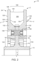
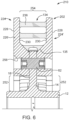
- FIGS. 5 to 8 another exemplary brake disc assembly 210 comprising a friction ring or brake disc 202 connected to a hub 12 is illustrated.
- the brake disc 202 is arranged to direct airflow through the brake disc 202 in the inverse direction from the airflow in the brake discs 2 described in connection with FIGS. 1 to 4 .
- the pumping effect described in connection with FIGS. 1 to 4 can be reduced or eliminated.
- cooling air may be drawn into the disc 202 through openings at the outer circumferential edge thereof and directed through the brake disc 202 towards outflow elements located adjacent to the hub 12 or axle of the brake assembly 210.
- the brake disc 202 comprises a plurality of segments 226 connected together to form a ring.
- the disc 202 can comprise about five segments, substantially identical in size and shape.
- the segments 226 can be connected together in a circumferential direction by pins or joining elements 238, extending between adjacent segments 226.
- the joining elements 238 can create gaps 236 between adjacent segments 226.
- the gap 236 permits expansion and contraction of the segments 226 during use.
- the segments 226 can comprise a front side 224 and a rear side 224', each having an outer surface 228, configured to be contacted by a brake surface to impart a braking force thereto, and an opposing inner surface 230.
- the front side 224 can be connected to and/or integrally formed with the rear side 224' to form a unitary structure.
- the segments 226 are fixed to the hub 12 at fixation points, such as through-holes 258 positioned at radially inward portions of the segments 226 and sized to receive pins 62.
- each segment 226 is fixed to the hub 12 at only one fixation point, such as a fixation point defined by a single through-hole 258. In this configuration, when connected to the hub 12, the segment 226 is capable of rotating about the single fixation point.
- the segments further comprise a plurality of protrusions extending between inner surfaces 230 of the sides 224, 224' of the segments 226.
- some of the protrusions are transversely extending elements, such as ribs 236.
- a transversely extending element or structure refers to a structure having a transverse cross-sectional area that is greater than its radial cross-sectional area.
- the ribs 236 can be integrally formed with the segments 226 or fixedly connected thereto.
- the ribs 236 may have a circular or elliptical radial cross section positioned to direct airflow passing through the segments 226 in a curved or curving airflow path. The airflow path is shown by arrow C in FIGS. 7 and 8 .
- the ribs 236 are positioned on the radially outer half or outer third of the segment 226, and arranged such that at least one radius R (shown in FIG. 8 ) of the segment 226 passes through at least two ribs 236.
- the through-hole 258 is positioned radially inwardly from the ribs 236.
- the segment 226 may further comprise a number of protrusions in the form of radially extending fins 235, similar in shape to fins 135 described in connection with FIGS. 1 to 4 .
- the fins 235 define channels 250 for directing airflow across the inner surface(s) of the segment 226.
- fins 235 extend from an inner circumferential surface of the middle portion of the segment 226.
- the brake disc assembly 210 is rotated by rotation of an axle connected to the hub 12, causing the brake disc 202 attached thereto to rotate as well.
- the rotation produces a centripetal effect in which air is drawn radially inwardly through each segment 226.
- an airflow path of cooling air C is drawn into the brake disc 202 at inflow portions 254 located adjacent to an outer circumferential edge of each segment 226.
- the ribs 236 only cover or block a small portion of the inflow portion 254 of each segment 226 meaning that a substantial volume of cooling air can be drawn into the segment 226 in this manner.
- the circumferentially outermost portions of each segment 226 may have only about three (3) to six (6), and preferably about four (4) ribs 236.
- the circumferentially outermost portions of the segment 126 shown in FIG. 4 includes about ten (10) to fifteen (15) fins 135, which cover or block about 40 to 60 percent of the airflow through the segment 126.
- a braking force is applied to the outer surface(s) 228 of the segments 226.
- the braking force is transmitted to the flange 14 and hub 12 by the protrusions (e.g., the fins 235 and ribs 236) of the segments 226 and the fastener 62 extending through the flange 14.
- the braking force can also cause the segments 226 to pivot about a fixation point defined by the through-hole 258, thereby transmitting force to adjacent segments 226.
- heat H (shown in FIG. 7 ) is created causing the contacted segments 226 to expand.
- the heat H is translated from the segments 226 through the protrusions (e.g., the fins 235 and ribs 236) to the flange 14 and hub 12.
- the heat H is counteracted by the cooling airflow C. Specifically, the airflow C passes around the ribs 236 and through the channels 250 defined by the fins 235.
- the heat H is transferred from the surfaces of the flange 14 and segments 226 to the cooling airflow C and is driven away from the brake disc assembly 210 through the outlet portions 252. In this way, heat H is ventilated away from the segment 226 and brake disc assembly 210 to improve braking performance and to prevent the segment 226, flange 14, and hub 12 from structurally degrading from prolonged use.
Landscapes
- Engineering & Computer Science (AREA)
- General Engineering & Computer Science (AREA)
- Mechanical Engineering (AREA)
- Braking Arrangements (AREA)
Claims (16)
- Bague de friction (24) comprenant :
une pluralité de segments (126, 226) configurée pour être fixée sur un moyeu (12) ou un essieu et agencée autour du moyeu ou de l'essieu afin de former un corps de forme annulaire, dans laquelle chacun des segments comprend :un côté avant (24) et un côté arrière (24'), chacun parmi le côté avant et le côté arrière comprenant une surface externe (128, 228) configurée pour être en contact avec un mécanisme de frein et une surface interne (130, 230) configurée pour être en contact avec une partie du moyeu (12) ou de l'essieu pour y communiquer une force de freinage ;dans laquelle chacun des segments comprend également un trou débouchant (158, 258) unique s'étendant entre la surface externe du côté avant et la surface externe du côté arrière du segment pour recevoir une fixation (62) afin de fixer le segment au moyeu (12) ou à l'essieu ; etau moins deux saillies (135, 235) s'étendant à partir de la surface interne (130, 230) du côté avant jusqu'à la surface interne du côté arrière du segment, les au moins deux saillies sont des ailettes s'étendant radialement et forment un canal radialement ouvert (150, 250) entre elles,dans laquelle, vue le long d'un plan parallèle à la face du segment de disque de frein, une zone transversale d'une partie d'entrée radialement interne (152, 254) du canal (150, 250) entre les au moins deux saillies est inférieure à une zone transversale d'une partie de sortie radialement externe (154, 252) du canal (150, 250) entre les au moins deux saillies, etcaractérisé en ce qu'au moins un segment de la pluralité de segments comprend une pluralité de nervures transversales (236), au moins une nervure transversale de la pluralité de nervures transversales s'étend entre les ailettes adjacentes s'étendant radialement, et la pluralité de nervures transversales est positionnée sur une moitié radialement externe du au moins un segment de la pluralité de segments et agencée de sorte qu'au moins un rayon de chaque segment passe par au moins deux nervures transversales de la pluralité de nervures transversales. - Bague de friction (24) selon la revendication 1, dans laquelle le canal (150, 250) s'étend entre un bord interne circonférentiel (146) et un bord externe circonférentiel (144) du segment (126, 226) et est positionné pour diriger l'écoulement d'air sur la surface interne du côté avant (24) ou la surface interne (130, 230) du côté arrière (24') du segment.
- Bague de friction (24) selon les revendications 1 ou 2, dans laquelle la partie d'entrée (154) du canal (150) est disposée radialement vers l'intérieur à partir de la partie de sortie (154) du canal (150), de sorte que l'écoulement d'air est dirigé d'un bord circonférentiel interne (146) à un bord circonférentiel externe (144) du segment (126, 226).
- Bague de friction (24) selon l'une quelconque des revendications 1 à 3, dans laquelle chacun des segments (126, 226) est configuré pour être fixé sur le moyeu (12) ou l'essieu à un point de fixation unique.
- Bague de friction (24) selon l'une quelconque des revendications 1 à 4, dans laquelle les ailettes s'étendant radialement (135, 235) sont progressivement rétrécies dans la direction radiale, de sorte que leur partie radialement interne est plus étroite que leur partie radialement externe, et dans une direction transversale, de sorte que les parties des ailettes adjacentes aux surfaces internes sont plus larges que les parties centrales des ailettes.
- Bague de friction (24) selon l'une quelconque des revendications 1 à 5, dans laquelle chacune des ailettes s'étendant radialement (135, 235) définit un axe longitudinal linéaire s'étendant à partir d'une partie radialement interne de l'ailette jusqu'à une partie radialement externe de l'ailette, et dans laquelle l'axe longitudinal linéaire de chaque ailette est décalé par rapport au rayon du segment (126, 226) d'au moins 5 degrés.
- Bague de friction (24) selon l'une quelconque des revendications 1 à 6, dans laquelle au moins une nervure transversale (236) de la pluralité de nervures transversales définit une trajectoire d'écoulement d'air courbe.
- Bague de friction (24) selon l'une quelconque des revendications 1 à 7, dans laquelle le trou débouchant (158, 258) unique est positionné radialement vers l'intérieur à partir de la pluralité de nervures transversales (236).
- Bague de friction (24) selon l'une quelconque des revendications 1 à 8, dans laquelle les au moins deux saillies (235) sont positionnées de sorte qu'une distance radiale commune de la bague de friction (24) passe par les au moins deux saillies (235).
- Disque de frein (2, 202) configuré pour être fixé sur un moyeu (12) et/ou sur un essieu à une pluralité de points de fixation, le disque de frein (2, 202) comprenant une pluralité de segments (126, 226) comprenant une bague de friction avant (24) et une bague de friction arrière (24'), dans lequel les bagues de friction (24) sont selon l'une quelconque des revendications 1 à 9.
- Disque de frein (2, 202) selon la revendication 10, dans lequel chaque segment (126, 226) est fixé sur le moyeu (12) et/ou sur l'essieu à un point de fixation unique.
- Disque de frein (2, 202) selon la revendication 11, dans lequel chaque segment (126, 226) est configuré de sorte que, lorsqu'il est fixé au moyeu (12) et/ou à l'essieu, chaque segment (126, 226) est autorisé à tourner autour d'un point de fixation unique.
- Ensemble de frein (10, 210) comprenant :un disque de frein (2, 202) selon l'une quelconque des revendications 10 à 12 ;un moyeu (12) configuré pour être raccordé à un essieu, le moyeu (12) comprenant un rotor central et une bride s'étendant radialement (14) encerclant au moins une partie du rotor central ; etune broche (62) fixée sur et s'étendant à travers la bride pour fixer le disque de frein (2, 202) à la bride.
- Ensemble de frein (10, 210) selon la revendication 13, dans lequel chacun de la pluralité de segments (126, 226) est fixé sur le moyeu (12) à un point de fixation unique.
- Ensemble de frein (10, 210) selon la revendication 14, dans lequel, lorsqu'il est fixé au moyeu (12), chaque segment (126, 226) peut tourner autour du point de fixation unique.
- Ensemble de frein (10, 210) selon l'une quelconque des revendications 13 à 15, dans lequel chacun de la pluralité de segments (126, 226) est fixé sur le moyeu (12) à un point de fixation unique afin de maximiser une zone d'entrée d'air, maximisant ainsi un flux d'air sur la surface interne de chaque corps de segment.
Priority Applications (1)
| Application Number | Priority Date | Filing Date | Title |
|---|---|---|---|
| EP22191821.2A EP4112965B1 (fr) | 2016-12-12 | 2017-09-19 | Disque de frein ventilé |
Applications Claiming Priority (2)
| Application Number | Priority Date | Filing Date | Title |
|---|---|---|---|
| US15/375,317 US10619689B2 (en) | 2016-12-12 | 2016-12-12 | Ventilated brake disc |
| PCT/US2017/052166 WO2018111366A1 (fr) | 2016-12-12 | 2017-09-19 | Disque de frein ventilé |
Related Child Applications (2)
| Application Number | Title | Priority Date | Filing Date |
|---|---|---|---|
| EP22191821.2A Division EP4112965B1 (fr) | 2016-12-12 | 2017-09-19 | Disque de frein ventilé |
| EP22191821.2A Division-Into EP4112965B1 (fr) | 2016-12-12 | 2017-09-19 | Disque de frein ventilé |
Publications (3)
| Publication Number | Publication Date |
|---|---|
| EP3551906A1 EP3551906A1 (fr) | 2019-10-16 |
| EP3551906A4 EP3551906A4 (fr) | 2020-07-08 |
| EP3551906B1 true EP3551906B1 (fr) | 2023-05-24 |
Family
ID=62489625
Family Applications (2)
| Application Number | Title | Priority Date | Filing Date |
|---|---|---|---|
| EP22191821.2A Active EP4112965B1 (fr) | 2016-12-12 | 2017-09-19 | Disque de frein ventilé |
| EP17880482.9A Active EP3551906B1 (fr) | 2016-12-12 | 2017-09-19 | Disque de frein ventilé |
Family Applications Before (1)
| Application Number | Title | Priority Date | Filing Date |
|---|---|---|---|
| EP22191821.2A Active EP4112965B1 (fr) | 2016-12-12 | 2017-09-19 | Disque de frein ventilé |
Country Status (7)
| Country | Link |
|---|---|
| US (2) | US10619689B2 (fr) |
| EP (2) | EP4112965B1 (fr) |
| KR (2) | KR102517077B1 (fr) |
| CN (2) | CN110062854B (fr) |
| AU (1) | AU2017377902B2 (fr) |
| MX (1) | MX2019006553A (fr) |
| WO (1) | WO2018111366A1 (fr) |
Families Citing this family (15)
| Publication number | Priority date | Publication date | Assignee | Title |
|---|---|---|---|---|
| ITUA20161411A1 (it) * | 2016-03-07 | 2017-09-07 | Freni Brembo Spa | Fascia frenante ventilata, assieme di disco freno ventilato e metodo di ventilazione |
| AU2019356796A1 (en) * | 2018-10-09 | 2021-03-18 | Disc Brakes Australia Pty. Limited | Disc brakes rotor and method of manufacture |
| DE102019135337B4 (de) * | 2018-12-28 | 2023-06-22 | Honda Motor Co., Ltd. | Aliminium-keramik-verbundwerkstoff-bremsbaugruppe |
| US10920840B2 (en) * | 2019-02-28 | 2021-02-16 | Volvo Car Corporation | Rotor assembly for a disc brake system |
| JP7778068B2 (ja) * | 2019-10-02 | 2025-12-01 | ブレンボ・ソチエタ・ペル・アツィオーニ | ベンチレーテッド型のディスクブレーキ用ブレーキバンド |
| AU2021203541B2 (en) * | 2020-06-19 | 2023-03-16 | Westinghouse Air Brake Technologies Corporation | Brake assembly |
| FR3112582B1 (fr) * | 2020-07-17 | 2022-08-05 | Alstom Transp Tech | Ensemble de disque pour frein à segments |
| US20230012996A1 (en) * | 2021-07-19 | 2023-01-19 | Poli S.R.L. | Brake system and method |
| DE202021106132U1 (de) * | 2021-11-10 | 2023-02-13 | Faiveley Transport Bochum GmbH | Reibring mit Befestigungselementen für Schienenrad |
| IT202200000809A1 (it) * | 2022-01-19 | 2023-07-19 | Brembo Spa | Dispositivo di frenatura |
| JP2025502445A (ja) * | 2022-01-19 | 2025-01-24 | ブレンボ・ソチエタ・ペル・アツィオーニ | ブレーキ装置 |
| IT202200000806A1 (it) * | 2022-01-19 | 2023-07-19 | Brembo Spa | Dispositivo di frenatura |
| DE102022102204B4 (de) * | 2022-01-31 | 2024-09-05 | Knorr-Bremse Systeme für Schienenfahrzeuge GmbH | Radbremsscheibe für Schienenfahrzeuge |
| US20230392658A1 (en) * | 2022-06-07 | 2023-12-07 | Transportation Ip Holdings, Llc | Thermal management device |
| JP2024112048A (ja) * | 2023-02-07 | 2024-08-20 | ヤマハ発動機株式会社 | ディスクブレーキ装置および鞍乗型車両 |
Citations (2)
| Publication number | Priority date | Publication date | Assignee | Title |
|---|---|---|---|---|
| DE19507922C2 (de) * | 1994-05-04 | 1997-04-30 | Bergische Stahlindustrie | Zusammengesetzte innenbelüftete Bremsscheibe |
| CN103591193B (zh) * | 2013-11-09 | 2016-02-03 | 常州南车铁马科技实业有限公司 | 分体式制动盘 |
Family Cites Families (54)
| Publication number | Priority date | Publication date | Assignee | Title |
|---|---|---|---|---|
| US2765881A (en) * | 1949-12-09 | 1956-10-09 | Raymond C Pierce | Brake rotor |
| FR1287967A (fr) | 1961-05-02 | 1962-03-16 | Knorr Bremse Gmbh | Disque de frein, en particulier pour véhicules sur rails |
| US3618729A (en) | 1969-08-25 | 1971-11-09 | Goodrich Co B F | Segmented friction member for brake or clutch |
| CH556985A (fr) | 1971-07-02 | 1974-12-13 | Messier Hispano Sa | Frein a disques, avec patins de friction en graphite. |
| DE2315134A1 (de) * | 1973-03-27 | 1974-10-10 | Kloeckner Werke Ag | Schienenfahrzeugrad mit bremsringsegmenten |
| GB1490743A (en) * | 1974-02-08 | 1977-11-02 | Dunlop Ltd | Wheel and disc brake assembly |
| US4132294A (en) * | 1976-07-23 | 1979-01-02 | Poli Off Mecc Spa | Braking disc with replaceable linings, for brake-discs |
| GB1599663A (en) | 1977-05-05 | 1981-10-07 | Girling Ltd | Disc assemblies for vehicle disc brakes |
| FR2498711B1 (fr) * | 1981-01-27 | 1986-04-11 | Valeo | Organe tournant de frein muni de canaux de ventilation |
| DE3114995A1 (de) | 1981-04-14 | 1982-11-11 | Knorr-Bremse GmbH, 8000 München | Radbremsscheibe fuer schienenfahrzeuge |
| DE3527577A1 (de) * | 1985-08-01 | 1987-02-05 | Bergische Stahlindustrie | Bremsscheibe fuer niedrige antriebsleistung |
| DE3814614A1 (de) | 1988-04-29 | 1989-11-09 | Knorr Bremse Ag | Wellenbremsscheibe fuer schienenfahrzeuge |
| GB8821630D0 (en) | 1988-09-02 | 1988-10-12 | Lucas Ind Plc | Improvements in disc assemblies for vehicle disc brakes |
| EP0427489B1 (fr) | 1989-11-07 | 1994-08-03 | SAB WABCO Holdings B.V. | Roues incorporant des disques de freinage |
| GB9005421D0 (en) | 1990-03-10 | 1990-05-09 | Lucas Ind Plc | Improvements relating to wheels incorporating brake discs |
| GB9005680D0 (en) | 1990-03-14 | 1990-05-09 | Lucas Ind Plc | Improvements relating to wheels incorporating braking discs |
| GB9211865D0 (en) | 1992-06-04 | 1992-07-15 | Wabco Holdings Sab | Improvements relating to braking discs |
| DE4325934A1 (de) | 1993-08-02 | 1995-02-09 | Knorr Bremse Ag | Gleitkopfschrauben-Verbindung |
| DE4417813A1 (de) | 1994-05-20 | 1995-11-23 | Knorr Bremse Systeme | Radbremsscheibe für Schienenfahrzeuge |
| IT1277455B1 (it) | 1995-08-07 | 1997-11-10 | Poli Off Mecc Spa | Supporto ruotante con dischi di frenatura in particolare per uso ferroviario |
| GB2307959B (en) * | 1995-12-05 | 1999-11-10 | T & N Technology Ltd | Disc brake rotors |
| US6216829B1 (en) * | 1998-12-31 | 2001-04-17 | Hayes Lemmerz International, Inc. | Rotor with tubular vent ducts |
| DE10028958B4 (de) | 2000-06-16 | 2013-07-25 | Faiveley Transport Remscheid Gmbh | Bremsscheibe für eine Scheibenbremse |
| DE10047980C2 (de) | 2000-09-28 | 2002-11-28 | Knorr Bremse Systeme | Radbremsscheibe für eine Schienenfahrzeugbremse |
| WO2004020862A1 (fr) * | 2002-08-30 | 2004-03-11 | Freni Brembo S.P.A. | Bande de freinage de frein a disques dotee de rainures |
| GB0300983D0 (en) * | 2003-01-16 | 2003-02-19 | A P Racing Ltd | Brake disc |
| DE10351592B3 (de) | 2003-11-05 | 2005-04-28 | Knorr Bremse Systeme | Bremsscheibe, insbesondere für ein Schienenfahrzeug |
| JP4509599B2 (ja) * | 2004-02-25 | 2010-07-21 | マツダ株式会社 | ブレーキディスクロータ |
| CN101203692A (zh) * | 2005-03-30 | 2008-06-18 | 费德罗-莫格尔公司 | 通风式盘式制动器转子 |
| DE202007009345U1 (de) | 2007-07-03 | 2007-08-30 | Faiveley Transport Remscheid Gmbh | Bremsscheibe mit Kühlrippen |
| US8794414B2 (en) * | 2007-09-10 | 2014-08-05 | Eaton Corporation | Coupling assembly |
| DE202007013658U1 (de) | 2007-09-28 | 2007-11-29 | Faiveley Transport Remscheid Gmbh | Bremsscheibe |
| DE102008003873A1 (de) | 2008-01-08 | 2009-07-09 | Siemens Aktiengesellschaft | Radbremsscheibe für ein Rad eines Fahrzeugs |
| EP2107266B1 (fr) * | 2008-04-01 | 2011-08-31 | Lucas Automotive GmbH | Disque de frein et frein à disque |
| DE102008033742B4 (de) * | 2008-07-18 | 2010-08-26 | Knorr-Bremse Systeme für Schienenfahrzeuge GmbH | Wellenbremsscheibe, insbesondere für ein Schienenfahrzeug |
| DE102008046546B4 (de) | 2008-09-10 | 2013-01-17 | Daimler Ag | Bremsscheibe mit Bremsscheibentopf |
| DE202008012661U1 (de) | 2008-09-22 | 2010-02-18 | Faiveley Transport Witten Gmbh | Rad, insbesondere Schienenrad für Schienenfahrzeuge |
| CN201335114Y (zh) * | 2008-12-09 | 2009-10-28 | 北京纵横机电技术开发公司 | 轮装制动盘装置 |
| WO2010108671A1 (fr) | 2009-03-27 | 2010-09-30 | Faiveley Transport Witten Gmbh | Disque de frein |
| DE202009006067U1 (de) | 2009-04-27 | 2009-07-02 | Faiveley Transport Witten Gmbh | Bremsring-Naben-Verbindung |
| DE202009007591U1 (de) | 2009-05-28 | 2009-08-06 | Faiveley Transport Witten Gmbh | Nabe, Bremsscheibe und Verbindungssystem |
| DE202009013476U1 (de) | 2009-10-06 | 2011-02-17 | Faiveley Transport Witten Gmbh | Bremsscheibe |
| DE202009014768U1 (de) | 2009-11-02 | 2011-03-24 | Faiveley Transport Witten Gmbh | Bremsscheibe |
| IT1396228B1 (it) | 2009-11-13 | 2012-11-16 | Freni Brembo Spa | Fascia di frenatura di un disco per freno a disco di tipo ventilato |
| DE202010001995U1 (de) | 2010-02-05 | 2010-04-15 | Faiveley Transport Witten Gmbh | Bremsscheibe |
| DE102010013160A1 (de) * | 2010-03-27 | 2011-09-29 | Bayerische Motoren Werke Aktiengesellschaft | Bremsscheibe |
| CZ22100U1 (cs) * | 2010-07-19 | 2011-04-21 | Gebauer@Marek | Axiálne a radiálne chlazený brzdový kotouc s krytem |
| DE202010015029U1 (de) | 2010-11-05 | 2012-04-02 | Faiveley Transport Witten Gmbh | Montagebuchse zur Montage von Tellerfedern, insbesondere an Radbremsscheiben für Schienenfahrzeuge |
| DE202011050872U1 (de) | 2011-08-01 | 2012-11-09 | Faiveley Transport Witten Gmbh | Schalteinrichtung zur Steuerung einer Magnetschienenbremse |
| DE202011052265U1 (de) * | 2011-12-12 | 2013-03-13 | Faiveley Transport Witten Gmbh | Gebaute Wellenbremsscheibe |
| US9587690B2 (en) | 2013-04-12 | 2017-03-07 | Wabtec Holding Corp. | Brake disc assembly for a wheel |
| US9371875B2 (en) | 2014-06-09 | 2016-06-21 | Ford Global Technologies, Llc | Ventilated brake rotors |
| US9709110B2 (en) * | 2015-07-07 | 2017-07-18 | Bendix Spicer Foundation Brake Llc | Brake disc ventilation arrangement |
| CN205154980U (zh) * | 2015-11-30 | 2016-04-13 | 中国铁道科学研究院 | 轮装制动盘装置 |
-
2016
- 2016-12-12 US US15/375,317 patent/US10619689B2/en active Active
-
2017
- 2017-09-19 KR KR1020197020059A patent/KR102517077B1/ko active Active
- 2017-09-19 EP EP22191821.2A patent/EP4112965B1/fr active Active
- 2017-09-19 MX MX2019006553A patent/MX2019006553A/es unknown
- 2017-09-19 KR KR1020227036607A patent/KR102560089B1/ko active Active
- 2017-09-19 AU AU2017377902A patent/AU2017377902B2/en active Active
- 2017-09-19 CN CN201780076993.2A patent/CN110062854B/zh active Active
- 2017-09-19 CN CN202111364477.4A patent/CN113864370B/zh active Active
- 2017-09-19 WO PCT/US2017/052166 patent/WO2018111366A1/fr not_active Ceased
- 2017-09-19 EP EP17880482.9A patent/EP3551906B1/fr active Active
-
2020
- 2020-03-11 US US16/815,654 patent/US20200208697A1/en not_active Abandoned
Patent Citations (2)
| Publication number | Priority date | Publication date | Assignee | Title |
|---|---|---|---|---|
| DE19507922C2 (de) * | 1994-05-04 | 1997-04-30 | Bergische Stahlindustrie | Zusammengesetzte innenbelüftete Bremsscheibe |
| CN103591193B (zh) * | 2013-11-09 | 2016-02-03 | 常州南车铁马科技实业有限公司 | 分体式制动盘 |
Also Published As
| Publication number | Publication date |
|---|---|
| US20180163802A1 (en) | 2018-06-14 |
| CN110062854A (zh) | 2019-07-26 |
| WO2018111366A1 (fr) | 2018-06-21 |
| AU2017377902A1 (en) | 2019-06-06 |
| EP3551906A1 (fr) | 2019-10-16 |
| BR112019009860A2 (pt) | 2019-08-20 |
| EP4112965A1 (fr) | 2023-01-04 |
| EP4112965B1 (fr) | 2023-12-20 |
| CN113864370B (zh) | 2024-11-29 |
| CN113864370A (zh) | 2021-12-31 |
| AU2017377902B2 (en) | 2023-07-27 |
| EP3551906A4 (fr) | 2020-07-08 |
| MX2019006553A (es) | 2019-08-26 |
| CN110062854B (zh) | 2021-12-07 |
| KR102560089B1 (ko) | 2023-07-27 |
| KR102517077B1 (ko) | 2023-04-03 |
| KR20220146699A (ko) | 2022-11-01 |
| US20200208697A1 (en) | 2020-07-02 |
| KR20190086776A (ko) | 2019-07-23 |
| US10619689B2 (en) | 2020-04-14 |
Similar Documents
| Publication | Publication Date | Title |
|---|---|---|
| EP3551906B1 (fr) | Disque de frein ventilé | |
| EP2984363B1 (fr) | Ensemble disque de frein pour une roue | |
| JP5211152B2 (ja) | 通風型ブレーキディスク | |
| US11384806B2 (en) | Braking band of a disc brake disc | |
| CN204200918U (zh) | 制动盘和车辆 | |
| US10794440B2 (en) | Internally ventilated brake disk | |
| CN103967980A (zh) | 具有强制散热筋的高速列车制动盘 | |
| US6193023B1 (en) | Rotor with alternate rib designs | |
| CN118934868A (zh) | 一种基于仿生鳞片结构的车辆制动盘 | |
| US11391335B2 (en) | Braking band of a disc for disc brake | |
| CN117836536A (zh) | 包括位于内盘和外盘之间的间隔支柱的自通风盘式制动器转子 | |
| US20070261929A1 (en) | Aerodynamic vented rotor | |
| RU122720U1 (ru) | Тормозной диск | |
| JP7364211B2 (ja) | ブレーキロータ | |
| BR112019009860B1 (pt) | Anel de atrito e conjunto de freio | |
| JP2000074109A (ja) | ベンチレーテッドディスクロータ |
Legal Events
| Date | Code | Title | Description |
|---|---|---|---|
| STAA | Information on the status of an ep patent application or granted ep patent |
Free format text: STATUS: THE INTERNATIONAL PUBLICATION HAS BEEN MADE |
|
| PUAI | Public reference made under article 153(3) epc to a published international application that has entered the european phase |
Free format text: ORIGINAL CODE: 0009012 |
|
| STAA | Information on the status of an ep patent application or granted ep patent |
Free format text: STATUS: REQUEST FOR EXAMINATION WAS MADE |
|
| 17P | Request for examination filed |
Effective date: 20190618 |
|
| AK | Designated contracting states |
Kind code of ref document: A1 Designated state(s): AL AT BE BG CH CY CZ DE DK EE ES FI FR GB GR HR HU IE IS IT LI LT LU LV MC MK MT NL NO PL PT RO RS SE SI SK SM TR |
|
| A4 | Supplementary search report drawn up and despatched |
Effective date: 20200609 |
|
| RIC1 | Information provided on ipc code assigned before grant |
Ipc: F16D 65/847 20060101AFI20200604BHEP Ipc: F16D 65/02 20060101ALI20200604BHEP |
|
| STAA | Information on the status of an ep patent application or granted ep patent |
Free format text: STATUS: EXAMINATION IS IN PROGRESS |
|
| 17Q | First examination report despatched |
Effective date: 20210309 |
|
| GRAP | Despatch of communication of intention to grant a patent |
Free format text: ORIGINAL CODE: EPIDOSNIGR1 |
|
| STAA | Information on the status of an ep patent application or granted ep patent |
Free format text: STATUS: GRANT OF PATENT IS INTENDED |
|
| INTG | Intention to grant announced |
Effective date: 20220509 |
|
| GRAJ | Information related to disapproval of communication of intention to grant by the applicant or resumption of examination proceedings by the epo deleted |
Free format text: ORIGINAL CODE: EPIDOSDIGR1 |
|
| STAA | Information on the status of an ep patent application or granted ep patent |
Free format text: STATUS: EXAMINATION IS IN PROGRESS |
|
| INTC | Intention to grant announced (deleted) | ||
| GRAP | Despatch of communication of intention to grant a patent |
Free format text: ORIGINAL CODE: EPIDOSNIGR1 |
|
| STAA | Information on the status of an ep patent application or granted ep patent |
Free format text: STATUS: GRANT OF PATENT IS INTENDED |
|
| INTG | Intention to grant announced |
Effective date: 20221028 |
|
| GRAS | Grant fee paid |
Free format text: ORIGINAL CODE: EPIDOSNIGR3 |
|
| GRAJ | Information related to disapproval of communication of intention to grant by the applicant or resumption of examination proceedings by the epo deleted |
Free format text: ORIGINAL CODE: EPIDOSDIGR1 |
|
| GRAL | Information related to payment of fee for publishing/printing deleted |
Free format text: ORIGINAL CODE: EPIDOSDIGR3 |
|
| STAA | Information on the status of an ep patent application or granted ep patent |
Free format text: STATUS: EXAMINATION IS IN PROGRESS |
|
| GRAP | Despatch of communication of intention to grant a patent |
Free format text: ORIGINAL CODE: EPIDOSNIGR1 |
|
| STAA | Information on the status of an ep patent application or granted ep patent |
Free format text: STATUS: GRANT OF PATENT IS INTENDED |
|
| INTC | Intention to grant announced (deleted) | ||
| GRAS | Grant fee paid |
Free format text: ORIGINAL CODE: EPIDOSNIGR3 |
|
| GRAA | (expected) grant |
Free format text: ORIGINAL CODE: 0009210 |
|
| STAA | Information on the status of an ep patent application or granted ep patent |
Free format text: STATUS: THE PATENT HAS BEEN GRANTED |
|
| INTG | Intention to grant announced |
Effective date: 20230403 |
|
| AK | Designated contracting states |
Kind code of ref document: B1 Designated state(s): AL AT BE BG CH CY CZ DE DK EE ES FI FR GB GR HR HU IE IS IT LI LT LU LV MC MK MT NL NO PL PT RO RS SE SI SK SM TR |
|
| REG | Reference to a national code |
Ref country code: GB Ref legal event code: FG4D |
|
| REG | Reference to a national code |
Ref country code: CH Ref legal event code: EP |
|
| REG | Reference to a national code |
Ref country code: DE Ref legal event code: R096 Ref document number: 602017069096 Country of ref document: DE |
|
| REG | Reference to a national code |
Ref country code: AT Ref legal event code: REF Ref document number: 1569659 Country of ref document: AT Kind code of ref document: T Effective date: 20230615 |
|
| REG | Reference to a national code |
Ref country code: IE Ref legal event code: FG4D |
|
| P01 | Opt-out of the competence of the unified patent court (upc) registered |
Effective date: 20230530 |
|
| REG | Reference to a national code |
Ref country code: LT Ref legal event code: MG9D |
|
| REG | Reference to a national code |
Ref country code: NL Ref legal event code: MP Effective date: 20230524 |
|
| REG | Reference to a national code |
Ref country code: AT Ref legal event code: MK05 Ref document number: 1569659 Country of ref document: AT Kind code of ref document: T Effective date: 20230524 |
|
| PG25 | Lapsed in a contracting state [announced via postgrant information from national office to epo] |
Ref country code: SE Free format text: LAPSE BECAUSE OF FAILURE TO SUBMIT A TRANSLATION OF THE DESCRIPTION OR TO PAY THE FEE WITHIN THE PRESCRIBED TIME-LIMIT Effective date: 20230524 Ref country code: PT Free format text: LAPSE BECAUSE OF FAILURE TO SUBMIT A TRANSLATION OF THE DESCRIPTION OR TO PAY THE FEE WITHIN THE PRESCRIBED TIME-LIMIT Effective date: 20230925 Ref country code: NO Free format text: LAPSE BECAUSE OF FAILURE TO SUBMIT A TRANSLATION OF THE DESCRIPTION OR TO PAY THE FEE WITHIN THE PRESCRIBED TIME-LIMIT Effective date: 20230824 Ref country code: NL Free format text: LAPSE BECAUSE OF FAILURE TO SUBMIT A TRANSLATION OF THE DESCRIPTION OR TO PAY THE FEE WITHIN THE PRESCRIBED TIME-LIMIT Effective date: 20230524 Ref country code: ES Free format text: LAPSE BECAUSE OF FAILURE TO SUBMIT A TRANSLATION OF THE DESCRIPTION OR TO PAY THE FEE WITHIN THE PRESCRIBED TIME-LIMIT Effective date: 20230524 Ref country code: AT Free format text: LAPSE BECAUSE OF FAILURE TO SUBMIT A TRANSLATION OF THE DESCRIPTION OR TO PAY THE FEE WITHIN THE PRESCRIBED TIME-LIMIT Effective date: 20230524 |
|
| PG25 | Lapsed in a contracting state [announced via postgrant information from national office to epo] |
Ref country code: RS Free format text: LAPSE BECAUSE OF FAILURE TO SUBMIT A TRANSLATION OF THE DESCRIPTION OR TO PAY THE FEE WITHIN THE PRESCRIBED TIME-LIMIT Effective date: 20230524 Ref country code: PL Free format text: LAPSE BECAUSE OF FAILURE TO SUBMIT A TRANSLATION OF THE DESCRIPTION OR TO PAY THE FEE WITHIN THE PRESCRIBED TIME-LIMIT Effective date: 20230524 Ref country code: LV Free format text: LAPSE BECAUSE OF FAILURE TO SUBMIT A TRANSLATION OF THE DESCRIPTION OR TO PAY THE FEE WITHIN THE PRESCRIBED TIME-LIMIT Effective date: 20230524 Ref country code: LT Free format text: LAPSE BECAUSE OF FAILURE TO SUBMIT A TRANSLATION OF THE DESCRIPTION OR TO PAY THE FEE WITHIN THE PRESCRIBED TIME-LIMIT Effective date: 20230524 Ref country code: IS Free format text: LAPSE BECAUSE OF FAILURE TO SUBMIT A TRANSLATION OF THE DESCRIPTION OR TO PAY THE FEE WITHIN THE PRESCRIBED TIME-LIMIT Effective date: 20230924 Ref country code: HR Free format text: LAPSE BECAUSE OF FAILURE TO SUBMIT A TRANSLATION OF THE DESCRIPTION OR TO PAY THE FEE WITHIN THE PRESCRIBED TIME-LIMIT Effective date: 20230524 Ref country code: GR Free format text: LAPSE BECAUSE OF FAILURE TO SUBMIT A TRANSLATION OF THE DESCRIPTION OR TO PAY THE FEE WITHIN THE PRESCRIBED TIME-LIMIT Effective date: 20230825 |
|
| PG25 | Lapsed in a contracting state [announced via postgrant information from national office to epo] |
Ref country code: FI Free format text: LAPSE BECAUSE OF FAILURE TO SUBMIT A TRANSLATION OF THE DESCRIPTION OR TO PAY THE FEE WITHIN THE PRESCRIBED TIME-LIMIT Effective date: 20230524 |
|
| PG25 | Lapsed in a contracting state [announced via postgrant information from national office to epo] |
Ref country code: SK Free format text: LAPSE BECAUSE OF FAILURE TO SUBMIT A TRANSLATION OF THE DESCRIPTION OR TO PAY THE FEE WITHIN THE PRESCRIBED TIME-LIMIT Effective date: 20230524 |
|
| PG25 | Lapsed in a contracting state [announced via postgrant information from national office to epo] |
Ref country code: SM Free format text: LAPSE BECAUSE OF FAILURE TO SUBMIT A TRANSLATION OF THE DESCRIPTION OR TO PAY THE FEE WITHIN THE PRESCRIBED TIME-LIMIT Effective date: 20230524 Ref country code: SK Free format text: LAPSE BECAUSE OF FAILURE TO SUBMIT A TRANSLATION OF THE DESCRIPTION OR TO PAY THE FEE WITHIN THE PRESCRIBED TIME-LIMIT Effective date: 20230524 Ref country code: RO Free format text: LAPSE BECAUSE OF FAILURE TO SUBMIT A TRANSLATION OF THE DESCRIPTION OR TO PAY THE FEE WITHIN THE PRESCRIBED TIME-LIMIT Effective date: 20230524 Ref country code: EE Free format text: LAPSE BECAUSE OF FAILURE TO SUBMIT A TRANSLATION OF THE DESCRIPTION OR TO PAY THE FEE WITHIN THE PRESCRIBED TIME-LIMIT Effective date: 20230524 Ref country code: DK Free format text: LAPSE BECAUSE OF FAILURE TO SUBMIT A TRANSLATION OF THE DESCRIPTION OR TO PAY THE FEE WITHIN THE PRESCRIBED TIME-LIMIT Effective date: 20230524 Ref country code: CZ Free format text: LAPSE BECAUSE OF FAILURE TO SUBMIT A TRANSLATION OF THE DESCRIPTION OR TO PAY THE FEE WITHIN THE PRESCRIBED TIME-LIMIT Effective date: 20230524 |
|
| REG | Reference to a national code |
Ref country code: DE Ref legal event code: R097 Ref document number: 602017069096 Country of ref document: DE |
|
| PLBE | No opposition filed within time limit |
Free format text: ORIGINAL CODE: 0009261 |
|
| STAA | Information on the status of an ep patent application or granted ep patent |
Free format text: STATUS: NO OPPOSITION FILED WITHIN TIME LIMIT |
|
| REG | Reference to a national code |
Ref country code: CH Ref legal event code: PL |
|
| 26N | No opposition filed |
Effective date: 20240227 |
|
| PG25 | Lapsed in a contracting state [announced via postgrant information from national office to epo] |
Ref country code: SI Free format text: LAPSE BECAUSE OF FAILURE TO SUBMIT A TRANSLATION OF THE DESCRIPTION OR TO PAY THE FEE WITHIN THE PRESCRIBED TIME-LIMIT Effective date: 20230524 |
|
| PG25 | Lapsed in a contracting state [announced via postgrant information from national office to epo] |
Ref country code: LU Free format text: LAPSE BECAUSE OF NON-PAYMENT OF DUE FEES Effective date: 20230919 |
|
| REG | Reference to a national code |
Ref country code: BE Ref legal event code: MM Effective date: 20230930 |
|
| PG25 | Lapsed in a contracting state [announced via postgrant information from national office to epo] |
Ref country code: SI Free format text: LAPSE BECAUSE OF FAILURE TO SUBMIT A TRANSLATION OF THE DESCRIPTION OR TO PAY THE FEE WITHIN THE PRESCRIBED TIME-LIMIT Effective date: 20230524 Ref country code: LU Free format text: LAPSE BECAUSE OF NON-PAYMENT OF DUE FEES Effective date: 20230919 Ref country code: MC Free format text: LAPSE BECAUSE OF FAILURE TO SUBMIT A TRANSLATION OF THE DESCRIPTION OR TO PAY THE FEE WITHIN THE PRESCRIBED TIME-LIMIT Effective date: 20230524 |
|
| REG | Reference to a national code |
Ref country code: IE Ref legal event code: MM4A |
|
| PG25 | Lapsed in a contracting state [announced via postgrant information from national office to epo] |
Ref country code: IE Free format text: LAPSE BECAUSE OF NON-PAYMENT OF DUE FEES Effective date: 20230919 |
|
| PG25 | Lapsed in a contracting state [announced via postgrant information from national office to epo] |
Ref country code: CH Free format text: LAPSE BECAUSE OF NON-PAYMENT OF DUE FEES Effective date: 20230930 |
|
| PG25 | Lapsed in a contracting state [announced via postgrant information from national office to epo] |
Ref country code: IE Free format text: LAPSE BECAUSE OF NON-PAYMENT OF DUE FEES Effective date: 20230919 Ref country code: CH Free format text: LAPSE BECAUSE OF NON-PAYMENT OF DUE FEES Effective date: 20230930 |
|
| PG25 | Lapsed in a contracting state [announced via postgrant information from national office to epo] |
Ref country code: BE Free format text: LAPSE BECAUSE OF NON-PAYMENT OF DUE FEES Effective date: 20230930 |
|
| PG25 | Lapsed in a contracting state [announced via postgrant information from national office to epo] |
Ref country code: BG Free format text: LAPSE BECAUSE OF FAILURE TO SUBMIT A TRANSLATION OF THE DESCRIPTION OR TO PAY THE FEE WITHIN THE PRESCRIBED TIME-LIMIT Effective date: 20230524 |
|
| PG25 | Lapsed in a contracting state [announced via postgrant information from national office to epo] |
Ref country code: BG Free format text: LAPSE BECAUSE OF FAILURE TO SUBMIT A TRANSLATION OF THE DESCRIPTION OR TO PAY THE FEE WITHIN THE PRESCRIBED TIME-LIMIT Effective date: 20230524 |
|
| PG25 | Lapsed in a contracting state [announced via postgrant information from national office to epo] |
Ref country code: CY Free format text: LAPSE BECAUSE OF FAILURE TO SUBMIT A TRANSLATION OF THE DESCRIPTION OR TO PAY THE FEE WITHIN THE PRESCRIBED TIME-LIMIT; INVALID AB INITIO Effective date: 20170919 |
|
| PG25 | Lapsed in a contracting state [announced via postgrant information from national office to epo] |
Ref country code: HU Free format text: LAPSE BECAUSE OF FAILURE TO SUBMIT A TRANSLATION OF THE DESCRIPTION OR TO PAY THE FEE WITHIN THE PRESCRIBED TIME-LIMIT; INVALID AB INITIO Effective date: 20170919 |
|
| PGFP | Annual fee paid to national office [announced via postgrant information from national office to epo] |
Ref country code: DE Payment date: 20250819 Year of fee payment: 9 |
|
| PGFP | Annual fee paid to national office [announced via postgrant information from national office to epo] |
Ref country code: IT Payment date: 20250818 Year of fee payment: 9 |
|
| PGFP | Annual fee paid to national office [announced via postgrant information from national office to epo] |
Ref country code: GB Payment date: 20250916 Year of fee payment: 9 |
|
| PGFP | Annual fee paid to national office [announced via postgrant information from national office to epo] |
Ref country code: FR Payment date: 20250915 Year of fee payment: 9 |
|
| PG25 | Lapsed in a contracting state [announced via postgrant information from national office to epo] |
Ref country code: TR Free format text: LAPSE BECAUSE OF FAILURE TO SUBMIT A TRANSLATION OF THE DESCRIPTION OR TO PAY THE FEE WITHIN THE PRESCRIBED TIME-LIMIT Effective date: 20230524 |