EP3551906B1 - Ventilated brake disc - Google Patents
Ventilated brake disc Download PDFInfo
- Publication number
- EP3551906B1 EP3551906B1 EP17880482.9A EP17880482A EP3551906B1 EP 3551906 B1 EP3551906 B1 EP 3551906B1 EP 17880482 A EP17880482 A EP 17880482A EP 3551906 B1 EP3551906 B1 EP 3551906B1
- Authority
- EP
- European Patent Office
- Prior art keywords
- segment
- hub
- segments
- brake disc
- brake
- Prior art date
- Legal status (The legal status is an assumption and is not a legal conclusion. Google has not performed a legal analysis and makes no representation as to the accuracy of the status listed.)
- Active
Links
Images


Classifications
-
- F—MECHANICAL ENGINEERING; LIGHTING; HEATING; WEAPONS; BLASTING
- F16—ENGINEERING ELEMENTS AND UNITS; GENERAL MEASURES FOR PRODUCING AND MAINTAINING EFFECTIVE FUNCTIONING OF MACHINES OR INSTALLATIONS; THERMAL INSULATION IN GENERAL
- F16D—COUPLINGS FOR TRANSMITTING ROTATION; CLUTCHES; BRAKES
- F16D65/00—Parts or details
- F16D65/02—Braking members; Mounting thereof
- F16D65/12—Discs; Drums for disc brakes
- F16D65/128—Discs; Drums for disc brakes characterised by means for cooling
-
- F—MECHANICAL ENGINEERING; LIGHTING; HEATING; WEAPONS; BLASTING
- F16—ENGINEERING ELEMENTS AND UNITS; GENERAL MEASURES FOR PRODUCING AND MAINTAINING EFFECTIVE FUNCTIONING OF MACHINES OR INSTALLATIONS; THERMAL INSULATION IN GENERAL
- F16D—COUPLINGS FOR TRANSMITTING ROTATION; CLUTCHES; BRAKES
- F16D65/00—Parts or details
- F16D65/78—Features relating to cooling
- F16D65/84—Features relating to cooling for disc brakes
- F16D65/847—Features relating to cooling for disc brakes with open cooling system, e.g. cooled by air
-
- F—MECHANICAL ENGINEERING; LIGHTING; HEATING; WEAPONS; BLASTING
- F16—ENGINEERING ELEMENTS AND UNITS; GENERAL MEASURES FOR PRODUCING AND MAINTAINING EFFECTIVE FUNCTIONING OF MACHINES OR INSTALLATIONS; THERMAL INSULATION IN GENERAL
- F16D—COUPLINGS FOR TRANSMITTING ROTATION; CLUTCHES; BRAKES
- F16D65/00—Parts or details
- F16D65/02—Braking members; Mounting thereof
- F16D65/12—Discs; Drums for disc brakes
- F16D65/123—Discs; Drums for disc brakes comprising an annular disc secured to a hub member; Discs characterised by means for mounting
-
- F—MECHANICAL ENGINEERING; LIGHTING; HEATING; WEAPONS; BLASTING
- F16—ENGINEERING ELEMENTS AND UNITS; GENERAL MEASURES FOR PRODUCING AND MAINTAINING EFFECTIVE FUNCTIONING OF MACHINES OR INSTALLATIONS; THERMAL INSULATION IN GENERAL
- F16D—COUPLINGS FOR TRANSMITTING ROTATION; CLUTCHES; BRAKES
- F16D65/00—Parts or details
- F16D65/02—Braking members; Mounting thereof
- F16D2065/13—Parts or details of discs or drums
- F16D2065/1304—Structure
- F16D2065/1312—Structure circumferentially segmented
-
- F—MECHANICAL ENGINEERING; LIGHTING; HEATING; WEAPONS; BLASTING
- F16—ENGINEERING ELEMENTS AND UNITS; GENERAL MEASURES FOR PRODUCING AND MAINTAINING EFFECTIVE FUNCTIONING OF MACHINES OR INSTALLATIONS; THERMAL INSULATION IN GENERAL
- F16D—COUPLINGS FOR TRANSMITTING ROTATION; CLUTCHES; BRAKES
- F16D65/00—Parts or details
- F16D65/02—Braking members; Mounting thereof
- F16D2065/13—Parts or details of discs or drums
- F16D2065/1304—Structure
- F16D2065/1316—Structure radially segmented
-
- F—MECHANICAL ENGINEERING; LIGHTING; HEATING; WEAPONS; BLASTING
- F16—ENGINEERING ELEMENTS AND UNITS; GENERAL MEASURES FOR PRODUCING AND MAINTAINING EFFECTIVE FUNCTIONING OF MACHINES OR INSTALLATIONS; THERMAL INSULATION IN GENERAL
- F16D—COUPLINGS FOR TRANSMITTING ROTATION; CLUTCHES; BRAKES
- F16D65/00—Parts or details
- F16D65/02—Braking members; Mounting thereof
- F16D2065/13—Parts or details of discs or drums
- F16D2065/1304—Structure
- F16D2065/1328—Structure internal cavities, e.g. cooling channels
-
- F—MECHANICAL ENGINEERING; LIGHTING; HEATING; WEAPONS; BLASTING
- F16—ENGINEERING ELEMENTS AND UNITS; GENERAL MEASURES FOR PRODUCING AND MAINTAINING EFFECTIVE FUNCTIONING OF MACHINES OR INSTALLATIONS; THERMAL INSULATION IN GENERAL
- F16D—COUPLINGS FOR TRANSMITTING ROTATION; CLUTCHES; BRAKES
- F16D65/00—Parts or details
- F16D65/02—Braking members; Mounting thereof
- F16D2065/13—Parts or details of discs or drums
- F16D2065/134—Connection
- F16D2065/1384—Connection to wheel hub
-
- F—MECHANICAL ENGINEERING; LIGHTING; HEATING; WEAPONS; BLASTING
- F16—ENGINEERING ELEMENTS AND UNITS; GENERAL MEASURES FOR PRODUCING AND MAINTAINING EFFECTIVE FUNCTIONING OF MACHINES OR INSTALLATIONS; THERMAL INSULATION IN GENERAL
- F16D—COUPLINGS FOR TRANSMITTING ROTATION; CLUTCHES; BRAKES
- F16D65/00—Parts or details
- F16D65/02—Braking members; Mounting thereof
- F16D2065/13—Parts or details of discs or drums
- F16D2065/134—Connection
- F16D2065/1388—Connection to shaft or axle
-
- F—MECHANICAL ENGINEERING; LIGHTING; HEATING; WEAPONS; BLASTING
- F16—ENGINEERING ELEMENTS AND UNITS; GENERAL MEASURES FOR PRODUCING AND MAINTAINING EFFECTIVE FUNCTIONING OF MACHINES OR INSTALLATIONS; THERMAL INSULATION IN GENERAL
- F16D—COUPLINGS FOR TRANSMITTING ROTATION; CLUTCHES; BRAKES
- F16D65/00—Parts or details
- F16D65/02—Braking members; Mounting thereof
- F16D2065/13—Parts or details of discs or drums
- F16D2065/134—Connection
- F16D2065/1392—Connection elements
-
- F—MECHANICAL ENGINEERING; LIGHTING; HEATING; WEAPONS; BLASTING
- F16—ENGINEERING ELEMENTS AND UNITS; GENERAL MEASURES FOR PRODUCING AND MAINTAINING EFFECTIVE FUNCTIONING OF MACHINES OR INSTALLATIONS; THERMAL INSULATION IN GENERAL
- F16D—COUPLINGS FOR TRANSMITTING ROTATION; CLUTCHES; BRAKES
- F16D65/00—Parts or details
- F16D65/02—Braking members; Mounting thereof
- F16D65/12—Discs; Drums for disc brakes
- F16D65/121—Discs; Drums for disc brakes consisting of at least three circumferentially arranged segments
Definitions
- the present invention relates to a friction ring, a brake assembly, and a brake disc for a rotating body, such as a wheel. More specifically, the brake disc relates to an annular brake disc with a ventilating structure for directing airflow across at least a portion of the disc to transfer heat therefrom.
- Brake discs are affixed to wheels or rotors for the purpose of providing a smooth, hard contact surface that can be contacted by a brake shoe or pad controlled by a brake mechanism, such as a brake jaw. When contact between the disc and shoe or pad is established, friction between the elements is sufficient to slow or stop rotation of the wheel.
- Disc brakes are commonly used in a variety of applications including, for example, industrial machines, such as cranes and lifts, as well as in conveying installations, such as escalators, elevators, ski-lifts, and the like.
- Disc brake assemblies are also employed in transport vehicles, such as rail cars, public transportation vehicles, trucks, and automobiles.
- United States Patent No. 4,132,294 to Poli entitled “Braking disc with replaceable linings, for brake-discs” (“the ⁇ 294 patent”) discloses an annular brake disc including radial fins or gills for directing airflow between front and rear brake discs of a brake assembly.
- the front and rear brake discs include openings on the disc surface located near the central portion of the wheel or wheel hub. Air is drawn into the openings and directed radially outward along the inner surface of the brake discs by the fins or gills. Heat created by the brake disc is transferred to the fins or gills and ventilated by the airflow. In this way, the fins or gills remove heat from the brake disc and wheel to improve performance thereof.
- a brake assembly Thermal expansion and degradation of a brake assembly is also addressed by the shape of the disc itself. More specifically, to make the brake linings and/or brake discs more accessible and to simplify maintenance, brake discs have been developed that are formed from two or more interlocking segments or friction rings, which can be individually removed and replaced. For example, the '294 patent discloses a disc brake including two or more linings disposed about a central hub.
- segmented disc brakes are known in which individual segments are spaced apart by a gap to permit the segments to expand when exposed to heat.
- United States Patent No. 5,788,026 to Poli entitled "Brake disc assembly for a rotational body” discloses a disc brake having a number of brake disc segments affixed to a rotating body to form an annular ring. Corresponding segments of the disc brake are attached to one another by fasteners extending through-holes in the segments and rotating body. The segments are also slidably connected to adjacent segments in the annular disc brake by joining elements or pins extending from a socket of a segment to a corresponding socket of the adjacent segment.
- United States Patent No. 4,132,294 entitled “Braking disc with replaceable linings, for brake discs”, discloses a braking disc comprising two annular linings on which the braking jaws are active, the latter being applied to a central driving hub mounted on the shaft to be braked.
- German Patent Application Publication No. DE19507922 entitled “Compound ventilated braking disc” discloses a composite internally ventilated brake disc for vehicle disc brakes, in particular rail vehicles, with a hub and friction rings attached to it.
- United States Patent Application Publication No. US2016/0076613 entitled “Brake disc assembly for a wheel”, discloses a brake disc for a rotating member, such as a wheel, and an annular brake disc formed from a plurality of interconnected brake disc segments.
- airflow volume and speed across the disc should be maximized to increase the cooling effect.
- the airflow pattern should be improved so that airflow is made available to portions of the disc that are most likely to be exposed to substantial heat.
- the brake disc disclosed herein is designed for such optimized and improved airflow.
- the brake assembly of the present invention provides a friction ring or brake disc that connects to a wheel, rotor, or hub and ventilates heat from the brake disc by directing airflow radially outward along an inner surface of the disc.
- the structure of the brake disc including radial protrusions or fins and placement of through-holes and fasteners, is designed to maximize ventilation through the disc.
- the present inventor recognized that through specific placement of the through-hole and fin structures, airflow between the disc and hub is effectively maximized. As a result of such airflow, damage from thermal stress and thermal expansion of the disc is effectively reduced. Accordingly, the brake disc assembly is less susceptible to wear-based damage and operates more quietly than known alternative systems.
- this invention is directed to a brake assembly configured to be connected to a hub or axel of a rotating body.
- the assembly addresses or overcomes some or all of the deficiencies and drawbacks associated with existing braking systems.
- a friction ring according to claim 1 is provided.
- a brake assembly according to claim 13 is provided.
- a brake disc according to claim 10 is provided.
- the present invention is directed to a friction ring or brake disc for a rotating body or wheel structure, such as a railway vehicle wheel.
- the friction ring or brake disc may be a unitary structure (e.g., a monobloc disc) or segmented, as illustrated in the accompanying figures.
- the brake disc may be used to restrict rotation of railway vehicle wheels and, specifically, for low speed rail vehicles having a speed of less than 200 km/hr.
- a brake disc refers to a structure adapted to connect to a rotating body and configured to be contacted by a braking mechanism, such as a brake jaw, brake pad, or brake shoe. Friction between the brake disc and shoe slows or stops rotation of the rotating body.
- Brake discs are generally either hub mounted or wheel mounted. Hub mounted brake discs (also referred to as an axle mounted disc) are connected to the hub or axle of the rotating body. In contrast, wheel mounted brake discs are connected directly to a surface of the wheel itself rather than to the hub or axle.
- the brake disc is configured to be fixed to the hub with the minimum number of fixation points allowed by safety calculations.
- Safety calculations can include computer modeling techniques for modeling forces exerted on the disc during use. Determining the minimum number of fixation points can consider, for example, the number of fixation points needed to form a stable and sufficiently strong connection between the brake disc and hub to ensure sufficient stopping power during use.
- each segment may be mounted to the hub at a single fixation point. The segment may be permitted to rotate about the single fixation point. Mounting the segment and/or disc to the hub at a minimum number of fixation points allows for creation of a disc with a maximized air inlet area, thereby providing maximum air flux across an inner surface of the brake disc and a highest possible ventilation.
- the assembly 10 includes a hub 12 with a radial flange 14 extending therefrom.
- the hub 12 may be configured to receive a rotating body, such as an axle of a railway vehicle or similar rotating structure.
- the flange 14 includes a front side surface 18 and a rear side surface 20 (shown in FIGS. 2 and 3 ).
- the flange 14 may be the same thickness throughout or may include regions having a different thicknesses or rigidity.
- the flange 14 may include alternating concentric bands (not shown) having high and low rigidity. The rigidity of the various regions may result from varying either the thickness or material composition of the flange 14.
- the assembly 10 further comprises a friction ring or brake disc 2 having a front side 24 connected to the front side surface 18 of the flange 14 and a rear side 24' (shown in FIGS. 2 and 3 ) connected to the rear side surface 20.
- a friction ring or brake disc 2 having a front side 24 connected to the front side surface 18 of the flange 14 and a rear side 24' (shown in FIGS. 2 and 3 ) connected to the rear side surface 20.
- a friction ring or brake disc 2 having a front side 24 connected to the front side surface 18 of the flange 14 and a rear side 24' (shown in FIGS. 2 and 3 ) connected to the rear side surface 20.
- the rear side 24' has a similar or identical structure as the front side 24 and, therefore, includes the features described hereinafter.
- the brake disc 2 is a segmented disc formed from a plurality of segments 126.
- the disc 2 can be formed from five substantially identically shaped segments. While a segmented brake disc 2 is described and illustrated herein, it is understood that the brake disc may also be a ring-shaped monobloc structure within the scope of the present invention.
- the segments 126 may be connected around the hub 12 to form a closed annular ring. The closed ring may be referred to as a friction ring.
- the segments 126 illustrated in FIG. 1 are the same size and shape, it is understood that the brake disc 2 may include segments having different shapes and sizes. The total number of segments may be even or odd.
- the segments 126 may be separated from one another by a radial gap 36 between the radial ends 142 of adjacent segments 126 so that the segments 126 can freely expand or contract depending on the temperature and force applied by the brake shoe or pad.
- the segments 126 are connected together by joining elements 38 extending across the gap 36.
- each segment 126 is connected to the adjacent segment 126 by one joining element 38 located near the outer circumferential side 144 of the segment 126.
- the brake disc 24 may include multiple joining elements 38 between each segment 126.
- the assembly 10 could include two joining elements 38 between each segment 126.
- the joining elements 38 may be positioned at equidistant positions from the central axis X of the segment 126.
- the joining element 38 may be a pin, fastener, or slider as is known in the art.
- the joining elements 38 are configured to be inserted in a socket 140 extending inward from the radial end 142 of each segment 126, such that each joining element 38 extends between corresponding sockets 140 of adjacent segments 126.
- the depth of each socket 140 is greater than the length of the associated joining element 38. Accordingly, the segments 126 are free to move, relative to the joining elements 38, causing the joining element 38 to insert farther into one segment 126 and to pull away from the adjacent segment 126.
- each side 24, 24' of each segment 126 comprises an outer surface 128, which functions as a standard braking surface.
- the outer surface 128 provides a substantially flat surface or face that is configured to be contacted by a brake surface, such as a brake shoe or pad controlled by a braking mechanism.
- the surface 128 may include regions that have been treated or machined to increase texture, hardness, or durability thereof to improve contact and, if necessary, to increase friction between the outer surface 128 and braking mechanism.
- Each side 24, 24' of each segment 126 also includes an inner surface 130 opposite the outer surface 128. A portion of the inner surface 130 is configured to contact the front side surface 18 and flange 14 to provide a stopping force F thereto when the brake assembly 10 is in use.
- the inner surface 130 of the segment 126 may include a thicker or wider portion 132 that physically contacts the front side surface 18 of the flange 14.
- the segment has a generally tapered appearance that is thicker adjacent to the hub 12 and thinner near the outer circumferential side 144 of the segment 126.
- the segments 126 may further comprise protrusions extending between the inner surfaces 130 of the front side 24 and the rear side 24' each segment 126.
- the protrusions comprise radially extending fins.
- the protrusions may comprise ribs, baffles, columns, walls, or any combination thereof.
- the protrusions may be integrally formed with the inner surface 130 of the segment 126 or attached thereto using a known adhesive or fastener.
- the protrusions are arranged to direct a cooling airflow C (shown in FIG.
- the front side 24 and the rear side 24' of the segments 126 are separated.
- the protrusions include contact surfaces that contact the surface of the wheel or rotating body.
- the sides 24, 24' are separated or divided in this manner, they are free to slide or move relative to one another.
- thermal expansion of the segments 126 is not restricted.
- thermal stresses caused by expansion are not translated between opposing segments 126, reducing the possibility that the protrusions will be damaged during use.
- the protrusions may be radial fins 135 having a long, thin structure with substantially flat opposing faces.
- the fins 135 are positioned to maximize ventilation through the brake disc assembly 10. Maximizing ventilation enhances cooling of the brake disc segments 126.
- the fins 135 may have a substantially rectangular or elliptical base area that contacts the inner surface 130 of the segment 126.
- the fins 135 may extend radially outwardly along the inner surface 130 of the segment 126 from the inner circumferential edge 146 thereof to the outer circumferential edge 144.
- the fins 135 may be tapered, becoming narrower as the distance from the inner surface(s) 130 increases.
- the fins 135 may also be wider near the inner circumferential side 146 of the segment 126 and narrower near the outer circumferential side 144, such that the distance between adjacent fins 135 increases farther away from the hub 12.
- the fins 135 extend radially outward from the inner circumferential side 146 directly along a radius of the segment 126.
- the fins 135 may be positioned elsewhere on the inner surface 130 of the segment 126 to obtain various airflow patterns.
- some of the fins 135 may be positioned such that a central axis of the fin 135 is angled (for example by at least 5 degrees) relative to the radius of the segment 126. In this orientation, distances between adjacent fins 135 increases substantially radially outward from the hub 12.
- a central axis of each fin 135 may be parallel to a central axis of adjacent fins.
- the fins 135 may also be different lengths, such that fins 135 located near the radial ends 142 of the segment 126 are longer than fins 135 near the center of the segment 126. As will be described hereinafter, having fins 135 with different lengths allows for various connection structures to be included on the inner surface 130 of the segment 126 for connecting the segment 126 to other segments 126 and/or to the hub 12 (shown in FIGS. 2 and 3 ).
- the fins 135 are positioned to define channels 150 between adjacent fins 135.
- the channels 150 are radially extending channels 150 as shown in FIGS. 1-4 .
- the channels 150 are enclosed by the radially extending sides of the fins 135, the inner surfaces 130 of the opposing sides 24, 24' of the segments 126, and the front and rear sides 18, 20 of the flange 14.
- External cool air enters the channels 150 through an inlet portion 152, located between the inner circumferential side 146 of the segment 126 and the hub 12, and passes through the channels 150 along cooling airflow C (shown in FIGS. 3 and 4 ).
- the air is expelled from the channels 150 through outlet portions 154 located near the outer circumferential side 144 of the segments 126.
- the inlet portion 152 may be an annular opening extending around the hub 12. Alternatively, in certain embodiments, the inlet portion(s) 152 may be a number of distinct holes, slots, or openings located around the hub 12.
- the outlet portion 154 may also be an annular opening, a partially annular opening, a slot, or a number of holes arranged around the outer circumferential side 144 of the segments 126. In each case, however, the cross-sectional area of the inlet portion 152, even if maximized, is less than the cross-sectional area of the outlet portion 154. Thus, the cross section area of the channels 150 increases farther away from the center of the disc 24.
- the increase in cross-sectional area between the inlet portion 152 and the outlet portion 154 causes the airflow rate or air speed to increase along the length of the channel 150.
- the increased air speed improves ventilation and cooling of the segment 126.
- the width of the channels 150 increases along its length, such that the width D of the channel 150 near the inlet portion 152 is less than the width E of the channel 150 at the outlet portion 154 (shown in FIG. 3 ).
- the fins 135 may be arranged in various patterns to increase airflow through the channels 150.
- the length of the fins 135 may vary, such that fins 135 located near the radial ends 142 of the segment 126 are longer than fins 135 in a central portion of each segment 126.
- fins 135 located near the radial ends 142 of the segment 126 may be contacted by a lateral member 156.
- the lateral member 156 may house the socket 140 and joining element 38 illustrated in FIG. 1 .
- the lateral member 156 may block or restrict airflow through the channels 150 located adjacent to the member 156, thereby forcing air through other channels 150.
- each segment 126 further includes at least one fixation point for connecting the segment 126 to the hub 12.
- the number of fixation points on each segment 126 is minimized to reduce the number of airflow restricting structures or protrusions extending from the inner surface 130 of the segment 126. Minimizing the number of airflow restricting structures maximizes the air flux between the segment 126 and wheel hub 12 leading to an improved ventilation effect.
- the segment 126 includes only a single fixation point, generally positioned near the inner circumferential side 146 of the segment 126.
- the fixation point may be a transverse through-hole 158 (not shown in FIG. 3 ) extending between the outer surface 128 (not shown in FIG. 4 ) and the inner surface 130 of the segment 126.
- each segment 126 includes only one transverse through-hole 158.
- the segment 126 may also include an extended portion 160 (shown in FIG. 4 ) or bracket to accommodate the through-hole 158.
- the through-hole 158 may be surrounded by the wider portion 132 of the inner surface 130.
- the wider portion 132 may be integrally formed with one of the fins 135.
- the wider portion 132 of the fins 135 restricts or limits airflow through the brake disc 24, reducing the effectiveness of the ventilation.
- the wider portion 132 may have a channel 150 on either side thereof.
- the arrangement and shape of the wider portion 132 of the inner surface 130 allows for good airflow to ventilate heat away from the wider portion 132 of the inner surface 130 and through-hole 158.
- Through-holes 158 are configured to receive a fastener 62, such as a pin, screw, or bolt, for connecting the brake disc 2 to the flange 14 of the hub 12.
- the flange 14 includes a bore 64 aligned with each through-hole 158 and configured to receive the fastener 62.
- the fastener 62 should be sufficiently strong to support loads generated by contact between the brake disc segments 126 and the brake surface. As described above, the present inventor recognized that the number of through-holes 158 should be minimized to increase airflow through the brake disc 24. Accordingly, the fastener 62 may have enhanced strength and resistance to deformation to absorb greater rotational forces created since the segment 126 is only connected to the hub 12 at a single fixed point.
- the fastener 62 may be inserted through the through-hole 158 and bore 64 of the flange 14 to rigidly and fixedly connect the segments 126 to the flange 14 and hub 12.
- the through-holes 158 may be deep enough so that a top portion of the fastener 62 is recessed within the through-hole 158 so that it does not extend above the through-hole 158 opening. Recessing the fastener 62 ensures that it does not contact or obstruct the brake surface, such as the brake shoe or brake pad.
- the brake disc assembly 10 is rotated by rotation of an axle connected to the hub 12, causing the brake disc 2 attached thereto to rotate as well.
- the rotation produces a centrifugal effect in which air is forced radially outward from the assembly 10 through outlet portions 154 defining by the segments 126.
- the radial fins 135 are arranged to produce a centrifugal pumping effect in which air is drawn into the channels 150 through the inlet portion 152 and expelled through the outlet portion 154 along cooling airflow path C shown in FIG. 3 .
- the braking force F is applied to the outer surface(s) 128 of the segments 126.
- the braking force F is transmitted to the flange 14 and hub 12 by the protrusions of the segments 126 and the fastener 62 extending through the flange 14. More particularly, the force F is applied in the circumferential direction causing the segments 126 contacted by the brake surface (e.g., the brake shoe or pads) to pivot about a fixation point defined by the through-hole 158, thereby transmitting force to adjacent segments 126 as well. Since the segments 126 are slidably connected by the joining elements 38, the segments 126 are permitted to pivot or rotate in response to the applied force.
- the brake surface e.g., the brake shoe or pads
- the airflow C is directed through the channels 150 and flows past the fins 135, flange 14, and inner surface 130 of the segment 126.
- the cooling airflow C also flows around the wider portion 132 of the inner surface 130 surrounding the through-hole 158.
- the heat H is transferred from the surfaces of the flange 14 and segments 126 to the airflow C and driven away from the brake disc assembly 10 through the outlet portion 154 as a result of the centrifugal pumping motion described above. In this way, heat H is ventilated away from the segment 126 and brake disc assembly 10 to improve braking performance and to prevent the segment 126, flange 14, and hub 12 from structurally degrading from prolonged use.
- FIGS. 5 to 8 another exemplary brake disc assembly 210 comprising a friction ring or brake disc 202 connected to a hub 12 is illustrated.
- the brake disc 202 is arranged to direct airflow through the brake disc 202 in the inverse direction from the airflow in the brake discs 2 described in connection with FIGS. 1 to 4 .
- the pumping effect described in connection with FIGS. 1 to 4 can be reduced or eliminated.
- cooling air may be drawn into the disc 202 through openings at the outer circumferential edge thereof and directed through the brake disc 202 towards outflow elements located adjacent to the hub 12 or axle of the brake assembly 210.
- the brake disc 202 comprises a plurality of segments 226 connected together to form a ring.
- the disc 202 can comprise about five segments, substantially identical in size and shape.
- the segments 226 can be connected together in a circumferential direction by pins or joining elements 238, extending between adjacent segments 226.
- the joining elements 238 can create gaps 236 between adjacent segments 226.
- the gap 236 permits expansion and contraction of the segments 226 during use.
- the segments 226 can comprise a front side 224 and a rear side 224', each having an outer surface 228, configured to be contacted by a brake surface to impart a braking force thereto, and an opposing inner surface 230.
- the front side 224 can be connected to and/or integrally formed with the rear side 224' to form a unitary structure.
- the segments 226 are fixed to the hub 12 at fixation points, such as through-holes 258 positioned at radially inward portions of the segments 226 and sized to receive pins 62.
- each segment 226 is fixed to the hub 12 at only one fixation point, such as a fixation point defined by a single through-hole 258. In this configuration, when connected to the hub 12, the segment 226 is capable of rotating about the single fixation point.
- the segments further comprise a plurality of protrusions extending between inner surfaces 230 of the sides 224, 224' of the segments 226.
- some of the protrusions are transversely extending elements, such as ribs 236.
- a transversely extending element or structure refers to a structure having a transverse cross-sectional area that is greater than its radial cross-sectional area.
- the ribs 236 can be integrally formed with the segments 226 or fixedly connected thereto.
- the ribs 236 may have a circular or elliptical radial cross section positioned to direct airflow passing through the segments 226 in a curved or curving airflow path. The airflow path is shown by arrow C in FIGS. 7 and 8 .
- the ribs 236 are positioned on the radially outer half or outer third of the segment 226, and arranged such that at least one radius R (shown in FIG. 8 ) of the segment 226 passes through at least two ribs 236.
- the through-hole 258 is positioned radially inwardly from the ribs 236.
- the segment 226 may further comprise a number of protrusions in the form of radially extending fins 235, similar in shape to fins 135 described in connection with FIGS. 1 to 4 .
- the fins 235 define channels 250 for directing airflow across the inner surface(s) of the segment 226.
- fins 235 extend from an inner circumferential surface of the middle portion of the segment 226.
- the brake disc assembly 210 is rotated by rotation of an axle connected to the hub 12, causing the brake disc 202 attached thereto to rotate as well.
- the rotation produces a centripetal effect in which air is drawn radially inwardly through each segment 226.
- an airflow path of cooling air C is drawn into the brake disc 202 at inflow portions 254 located adjacent to an outer circumferential edge of each segment 226.
- the ribs 236 only cover or block a small portion of the inflow portion 254 of each segment 226 meaning that a substantial volume of cooling air can be drawn into the segment 226 in this manner.
- the circumferentially outermost portions of each segment 226 may have only about three (3) to six (6), and preferably about four (4) ribs 236.
- the circumferentially outermost portions of the segment 126 shown in FIG. 4 includes about ten (10) to fifteen (15) fins 135, which cover or block about 40 to 60 percent of the airflow through the segment 126.
- a braking force is applied to the outer surface(s) 228 of the segments 226.
- the braking force is transmitted to the flange 14 and hub 12 by the protrusions (e.g., the fins 235 and ribs 236) of the segments 226 and the fastener 62 extending through the flange 14.
- the braking force can also cause the segments 226 to pivot about a fixation point defined by the through-hole 258, thereby transmitting force to adjacent segments 226.
- heat H (shown in FIG. 7 ) is created causing the contacted segments 226 to expand.
- the heat H is translated from the segments 226 through the protrusions (e.g., the fins 235 and ribs 236) to the flange 14 and hub 12.
- the heat H is counteracted by the cooling airflow C. Specifically, the airflow C passes around the ribs 236 and through the channels 250 defined by the fins 235.
- the heat H is transferred from the surfaces of the flange 14 and segments 226 to the cooling airflow C and is driven away from the brake disc assembly 210 through the outlet portions 252. In this way, heat H is ventilated away from the segment 226 and brake disc assembly 210 to improve braking performance and to prevent the segment 226, flange 14, and hub 12 from structurally degrading from prolonged use.
Landscapes
- Engineering & Computer Science (AREA)
- General Engineering & Computer Science (AREA)
- Mechanical Engineering (AREA)
- Braking Arrangements (AREA)
Description
- This application claims priority to
United States Patent Application No. 15/375,317 filed December 12, 2016 - The present invention relates to a friction ring, a brake assembly, and a brake disc for a rotating body, such as a wheel. More specifically, the brake disc relates to an annular brake disc with a ventilating structure for directing airflow across at least a portion of the disc to transfer heat therefrom.
- Brake discs are affixed to wheels or rotors for the purpose of providing a smooth, hard contact surface that can be contacted by a brake shoe or pad controlled by a brake mechanism, such as a brake jaw. When contact between the disc and shoe or pad is established, friction between the elements is sufficient to slow or stop rotation of the wheel. Disc brakes are commonly used in a variety of applications including, for example, industrial machines, such as cranes and lifts, as well as in conveying installations, such as escalators, elevators, ski-lifts, and the like. Disc brake assemblies are also employed in transport vehicles, such as rail cars, public transportation vehicles, trucks, and automobiles.
- It is well known that significant heat is created as a result of the frictional contact between the brake shoe and brake disc. The heat may cause thermal expansion of portions of the brake assembly and may cause the brake assembly to deform or degrade following prolonged use. More particularly, known braking apparatus often do not permit uniform distribution of the generated heat leading to wide temperature gradients across the braking assembly. Such temperature gradients may cause fissures and cracks to form in the brake disc. Additionally, cooling airflow is often neither sufficiently uniform nor adequate to counteract the destructive effects of the heat being generated. Instead, cooling air may actually increase temperature gradients on the brake disc worsening thermal transitional phenomena. Additionally, a considerable amount of the heat created on the contact surface of the brake element is transferred to the shaft on which the brake disc is mounted. This transferred heat may cause oxidation to occur on the shaft and/or wheel making replacing brake elements more difficult. Prolonged heat exposure also alters the centering or calibration of the brake elements and/or drive members further affecting performance of the brake system and wheel.
-
United States Patent No. 4,132,294 to Poli , entitled "Braking disc with replaceable linings, for brake-discs" ("the `294 patent") discloses an annular brake disc including radial fins or gills for directing airflow between front and rear brake discs of a brake assembly. The front and rear brake discs include openings on the disc surface located near the central portion of the wheel or wheel hub. Air is drawn into the openings and directed radially outward along the inner surface of the brake discs by the fins or gills. Heat created by the brake disc is transferred to the fins or gills and ventilated by the airflow. In this way, the fins or gills remove heat from the brake disc and wheel to improve performance thereof. - Thermal expansion and degradation of a brake assembly is also addressed by the shape of the disc itself. More specifically, to make the brake linings and/or brake discs more accessible and to simplify maintenance, brake discs have been developed that are formed from two or more interlocking segments or friction rings, which can be individually removed and replaced. For example, the '294 patent discloses a disc brake including two or more linings disposed about a central hub.
- Other segmented disc brakes are known in which individual segments are spaced apart by a gap to permit the segments to expand when exposed to heat. For example,
United States Patent No. 5,788,026 to Poli , entitled "Brake disc assembly for a rotational body" discloses a disc brake having a number of brake disc segments affixed to a rotating body to form an annular ring. Corresponding segments of the disc brake are attached to one another by fasteners extending through-holes in the segments and rotating body. The segments are also slidably connected to adjacent segments in the annular disc brake by joining elements or pins extending from a socket of a segment to a corresponding socket of the adjacent segment. In this way, the segments may move and expand in response to heat, friction, and pressure caused by contact between the disc brake and brake mechanism.United States Patent No. 4,132,294 , entitled "Braking disc with replaceable linings, for brake discs", discloses a braking disc comprising two annular linings on which the braking jaws are active, the latter being applied to a central driving hub mounted on the shaft to be braked.German Patent Application Publication No. DE19507922 , entitled "Compound ventilated braking disc", discloses a composite internally ventilated brake disc for vehicle disc brakes, in particular rail vehicles, with a hub and friction rings attached to it. United States Patent Application Publication No.US2016/0076613 , entitled "Brake disc assembly for a wheel", discloses a brake disc for a rotating member, such as a wheel, and an annular brake disc formed from a plurality of interconnected brake disc segments. - However, a need exists for a brake disc with improved cooling and ventilating structures. Particularly, airflow volume and speed across the disc should be maximized to increase the cooling effect. Furthermore, the airflow pattern should be improved so that airflow is made available to portions of the disc that are most likely to be exposed to substantial heat. The brake disc disclosed herein is designed for such optimized and improved airflow.
- In view of the foregoing, the brake assembly of the present invention provides a friction ring or brake disc that connects to a wheel, rotor, or hub and ventilates heat from the brake disc by directing airflow radially outward along an inner surface of the disc. The structure of the brake disc, including radial protrusions or fins and placement of through-holes and fasteners, is designed to maximize ventilation through the disc. Particularly, the present inventor recognized that through specific placement of the through-hole and fin structures, airflow between the disc and hub is effectively maximized. As a result of such airflow, damage from thermal stress and thermal expansion of the disc is effectively reduced. Accordingly, the brake disc assembly is less susceptible to wear-based damage and operates more quietly than known alternative systems.
- Generally, this invention is directed to a brake assembly configured to be connected to a hub or axel of a rotating body. Advantageously, the assembly addresses or overcomes some or all of the deficiencies and drawbacks associated with existing braking systems.
- According to an aspect of the invention, a friction ring according to
claim 1 is provided. - According to another aspect of the invention, a brake assembly according to claim 13 is provided.
- According to another aspect of the invention, a brake disc according to
claim 10 is provided. - The foregoing and other features and characteristics, as well as the methods of operation and functions of the related elements of structures and the combination of parts and economies of manufacture, will become more apparent upon consideration of the following description and the appended claims with reference to the accompanying drawings, all of which form a part of this specification, wherein like reference numerals designate corresponding parts in the various figures. It is to be expressly understood, however, that the drawings are for the purpose of illustration and description only and are not intended as a definition of the limits of the invention. As used in the specification and the claims, the singular form of "a", "an", and "the" include plural referents unless the context clearly dictates otherwise.
- Some of the advantages and features of the preferred embodiments of the invention have been summarized hereinabove. These embodiments, along with other potential embodiments of the device, will become apparent to those skilled in the art when referencing the following drawings in conjunction with the detailed descriptions as they relate to the figures.
-
FIG. 1 is a front view of a brake disc assembly according to an embodiment of the invention; -
FIG. 2 is a cross-sectional view of a portion of the assembly ofFIG. 1 along line A-A inFIG. 1 ; -
FIG. 3 is a cross-sectional view of a portion of the assembly ofFIG. 1 along line B-B inFIG. 1 ; -
FIG. 4 is a cross-sectional view of a portion of the assembly ofFIG. 1 taken along a plane parallel to the face of the brake disc segment; -
FIG. 5 is a front view of another exemplary brake disc assembly according to an embodiment of the invention; -
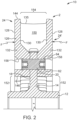
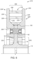
FIG. 6 is a cross-sectional view of a portion of the assembly ofFIG. 5 along line A2-A2 inFIG. 5 ; -
FIG. 7 is a cross-sectional view of a portion of the assembly ofFIG. 5 along line B2-B2 inFIG. 5 ; and -
FIG. 8 is a cross-sectional view of a portion of the assembly ofFIG. 1 taken along a plane parallel to the face of the brake disc segment. - The following description is provided to enable those skilled in the art to make and use the described embodiments contemplated for carrying out the invention. It is also to be understood that the specific devices illustrated in the attached drawings, and described in the following specification, are simply exemplary embodiments of the invention. Hence, specific dimensions and other physical characteristics related to the embodiments disclosed herein are not to be considered as limiting. For the purpose of facilitating understanding of the invention, the accompanying drawings and description illustrate preferred embodiments thereof, from which the invention, various embodiments of its structures, construction and method of operation, and many advantages may be understood and appreciated.
- For purposes of the description hereinafter, the terms "end", "upper", "lower", "right", "left", "vertical", "horizontal", "top", "bottom", "lateral", "longitudinal", and derivatives thereof shall relate to the invention as it is oriented in the drawing figures.
- The present invention is directed to a friction ring or brake disc for a rotating body or wheel structure, such as a railway vehicle wheel. The friction ring or brake disc may be a unitary structure (e.g., a monobloc disc) or segmented, as illustrated in the accompanying figures. The brake disc may be used to restrict rotation of railway vehicle wheels and, specifically, for low speed rail vehicles having a speed of less than 200 km/hr. A brake disc refers to a structure adapted to connect to a rotating body and configured to be contacted by a braking mechanism, such as a brake jaw, brake pad, or brake shoe. Friction between the brake disc and shoe slows or stops rotation of the rotating body. Brake discs are generally either hub mounted or wheel mounted. Hub mounted brake discs (also referred to as an axle mounted disc) are connected to the hub or axle of the rotating body. In contrast, wheel mounted brake discs are connected directly to a surface of the wheel itself rather than to the hub or axle.
- In some examples, the brake disc is configured to be fixed to the hub with the minimum number of fixation points allowed by safety calculations. Safety calculations can include computer modeling techniques for modeling forces exerted on the disc during use. Determining the minimum number of fixation points can consider, for example, the number of fixation points needed to form a stable and sufficiently strong connection between the brake disc and hub to ensure sufficient stopping power during use. In the case of a segmented brake disc, each segment may be mounted to the hub at a single fixation point. The segment may be permitted to rotate about the single fixation point. Mounting the segment and/or disc to the hub at a minimum number of fixation points allows for creation of a disc with a maximized air inlet area, thereby providing maximum air flux across an inner surface of the brake disc and a highest possible ventilation.
- With reference to
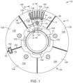
FIGS. 1 to 3 , a hub mountedbrake disc assembly 10 is illustrated; however, it is understood that theassembly 10 could also be adapted to mount directly to a wheel body within the scope of the present invention. Theassembly 10 includes ahub 12 with aradial flange 14 extending therefrom. Thehub 12 may be configured to receive a rotating body, such as an axle of a railway vehicle or similar rotating structure. Theflange 14 includes afront side surface 18 and a rear side surface 20 (shown inFIGS. 2 and3 ). Theflange 14 may be the same thickness throughout or may include regions having a different thicknesses or rigidity. For example, theflange 14 may include alternating concentric bands (not shown) having high and low rigidity. The rigidity of the various regions may result from varying either the thickness or material composition of theflange 14. - The
assembly 10 further comprises a friction ring orbrake disc 2 having afront side 24 connected to thefront side surface 18 of theflange 14 and a rear side 24' (shown inFIGS. 2 and3 ) connected to therear side surface 20. Generally, it is preferable to affix thesides 24, 24' of thebrake disc 2 to a more rigid region of theflange 14 to improve braking performance. In the following discussion, the structure of thefront side 24 is described. The rear side 24' has a similar or identical structure as thefront side 24 and, therefore, includes the features described hereinafter. - With specific reference to
FIG. 1 , thebrake disc 2 is a segmented disc formed from a plurality ofsegments 126. For example, thedisc 2 can be formed from five substantially identically shaped segments. While asegmented brake disc 2 is described and illustrated herein, it is understood that the brake disc may also be a ring-shaped monobloc structure within the scope of the present invention. As shown inFIG. 1 , thesegments 126 may be connected around thehub 12 to form a closed annular ring. The closed ring may be referred to as a friction ring. While thesegments 126 illustrated inFIG. 1 are the same size and shape, it is understood that thebrake disc 2 may include segments having different shapes and sizes. The total number of segments may be even or odd. - The
segments 126 may be separated from one another by aradial gap 36 between the radial ends 142 ofadjacent segments 126 so that thesegments 126 can freely expand or contract depending on the temperature and force applied by the brake shoe or pad. Thesegments 126 are connected together by joiningelements 38 extending across thegap 36. In the embodiment of thedisc assembly 10 shown inFIG. 1 , eachsegment 126 is connected to theadjacent segment 126 by one joiningelement 38 located near the outercircumferential side 144 of thesegment 126. In certain embodiments, thebrake disc 24 may include multiple joiningelements 38 between eachsegment 126. For example, theassembly 10 could include two joiningelements 38 between eachsegment 126. The joiningelements 38 may be positioned at equidistant positions from the central axis X of thesegment 126. The joiningelement 38 may be a pin, fastener, or slider as is known in the art. The joiningelements 38 are configured to be inserted in asocket 140 extending inward from theradial end 142 of eachsegment 126, such that each joiningelement 38 extends betweencorresponding sockets 140 ofadjacent segments 126. In one embodiment, the depth of eachsocket 140 is greater than the length of the associated joiningelement 38. Accordingly, thesegments 126 are free to move, relative to the joiningelements 38, causing the joiningelement 38 to insert farther into onesegment 126 and to pull away from theadjacent segment 126. - With specific reference to
FIGS. 2 and3 , eachside 24, 24' of eachsegment 126 comprises anouter surface 128, which functions as a standard braking surface. Theouter surface 128 provides a substantially flat surface or face that is configured to be contacted by a brake surface, such as a brake shoe or pad controlled by a braking mechanism. Optionally, thesurface 128 may include regions that have been treated or machined to increase texture, hardness, or durability thereof to improve contact and, if necessary, to increase friction between theouter surface 128 and braking mechanism. Eachside 24, 24' of eachsegment 126 also includes aninner surface 130 opposite theouter surface 128. A portion of theinner surface 130 is configured to contact thefront side surface 18 andflange 14 to provide a stopping force F thereto when thebrake assembly 10 is in use. As shown inFIG. 2 , to facilitate contact between thesegment 126 andflange 14, theinner surface 130 of thesegment 126 may include a thicker orwider portion 132 that physically contacts thefront side surface 18 of theflange 14. In that case, the segment has a generally tapered appearance that is thicker adjacent to thehub 12 and thinner near the outercircumferential side 144 of thesegment 126. - With continued reference to
FIGS. 2 and3 , thesegments 126 may further comprise protrusions extending between theinner surfaces 130 of thefront side 24 and the rear side 24' eachsegment 126. In some embodiments, as shown inFIGS. 1 to 4 , the protrusions comprise radially extending fins. In other embodiments, the protrusions may comprise ribs, baffles, columns, walls, or any combination thereof. The protrusions may be integrally formed with theinner surface 130 of thesegment 126 or attached thereto using a known adhesive or fastener. The protrusions are arranged to direct a cooling airflow C (shown inFIG. 3 ) or air flux across the surface of theflange 14 andinner surface 130 of thesegment 126 for ventilating and cooling theflange 14 andsegment 126. Providing a continual supply of cool air when thedisc assembly 10 is in use counteracts the effect of heat created from the contact between thesegment 126 and braking mechanism. Cooling and ventilating thesegment 126 provides a more even temperature gradient across thesegment 126 that prevents degradation of thesegment 126 as a result of thermal stresses and thermal expansion. - It is noted that for a wheel mounted brake disc, the
front side 24 and the rear side 24' of thesegments 126 are separated. In that case, the protrusions include contact surfaces that contact the surface of the wheel or rotating body. Advantageously, when thesides 24, 24' are separated or divided in this manner, they are free to slide or move relative to one another. As a result, thermal expansion of thesegments 126 is not restricted. Similarly, thermal stresses caused by expansion are not translated between opposingsegments 126, reducing the possibility that the protrusions will be damaged during use. - With continued reference to
FIGS. 2 and3 , as well asFIG. 4 , the protrusions may beradial fins 135 having a long, thin structure with substantially flat opposing faces. Thefins 135 are positioned to maximize ventilation through thebrake disc assembly 10. Maximizing ventilation enhances cooling of thebrake disc segments 126. As shown inFIG. 4 , thefins 135 may have a substantially rectangular or elliptical base area that contacts theinner surface 130 of thesegment 126. Thefins 135 may extend radially outwardly along theinner surface 130 of thesegment 126 from the innercircumferential edge 146 thereof to the outercircumferential edge 144. Thefins 135 may be tapered, becoming narrower as the distance from the inner surface(s) 130 increases. Thefins 135 may also be wider near the innercircumferential side 146 of thesegment 126 and narrower near the outercircumferential side 144, such that the distance betweenadjacent fins 135 increases farther away from thehub 12. - The
fins 135 extend radially outward from the innercircumferential side 146 directly along a radius of thesegment 126. Alternatively, thefins 135 may be positioned elsewhere on theinner surface 130 of thesegment 126 to obtain various airflow patterns. For example, in certain embodiments, some of thefins 135 may be positioned such that a central axis of thefin 135 is angled (for example by at least 5 degrees) relative to the radius of thesegment 126. In this orientation, distances betweenadjacent fins 135 increases substantially radially outward from thehub 12. In certain other embodiments, a central axis of eachfin 135 may be parallel to a central axis of adjacent fins. Thefins 135 may also be different lengths, such thatfins 135 located near the radial ends 142 of thesegment 126 are longer thanfins 135 near the center of thesegment 126. As will be described hereinafter, havingfins 135 with different lengths allows for various connection structures to be included on theinner surface 130 of thesegment 126 for connecting thesegment 126 toother segments 126 and/or to the hub 12 (shown inFIGS. 2 and3 ). - The
fins 135 are positioned to definechannels 150 betweenadjacent fins 135. Thechannels 150 are radially extendingchannels 150 as shown inFIGS. 1-4 . Thechannels 150 are enclosed by the radially extending sides of thefins 135, theinner surfaces 130 of the opposingsides 24, 24' of thesegments 126, and the front andrear sides flange 14. External cool air enters thechannels 150 through aninlet portion 152, located between the innercircumferential side 146 of thesegment 126 and thehub 12, and passes through thechannels 150 along cooling airflow C (shown inFIGS. 3 and4 ). The air is expelled from thechannels 150 throughoutlet portions 154 located near the outercircumferential side 144 of thesegments 126. Theinlet portion 152 may be an annular opening extending around thehub 12. Alternatively, in certain embodiments, the inlet portion(s) 152 may be a number of distinct holes, slots, or openings located around thehub 12. Theoutlet portion 154 may also be an annular opening, a partially annular opening, a slot, or a number of holes arranged around the outercircumferential side 144 of thesegments 126. In each case, however, the cross-sectional area of theinlet portion 152, even if maximized, is less than the cross-sectional area of theoutlet portion 154. Thus, the cross section area of thechannels 150 increases farther away from the center of thedisc 24. - With specific reference to
FIG. 4 , the increase in cross-sectional area between theinlet portion 152 and theoutlet portion 154 causes the airflow rate or air speed to increase along the length of thechannel 150. The increased air speed improves ventilation and cooling of thesegment 126. To achieve the change in cross-sectional area, in certain embodiments, the width of thechannels 150 increases along its length, such that the width D of thechannel 150 near theinlet portion 152 is less than the width E of thechannel 150 at the outlet portion 154 (shown inFIG. 3 ). - The
fins 135 may be arranged in various patterns to increase airflow through thechannels 150. For example, as described above, the length of thefins 135 may vary, such thatfins 135 located near the radial ends 142 of thesegment 126 are longer thanfins 135 in a central portion of eachsegment 126. In addition,fins 135 located near the radial ends 142 of thesegment 126 may be contacted by alateral member 156. Thelateral member 156 may house thesocket 140 and joiningelement 38 illustrated inFIG. 1 . Thelateral member 156 may block or restrict airflow through thechannels 150 located adjacent to themember 156, thereby forcing air throughother channels 150. - With reference again to
FIGS. 2 to 4 , eachsegment 126 further includes at least one fixation point for connecting thesegment 126 to thehub 12. Desirably, the number of fixation points on eachsegment 126 is minimized to reduce the number of airflow restricting structures or protrusions extending from theinner surface 130 of thesegment 126. Minimizing the number of airflow restricting structures maximizes the air flux between thesegment 126 andwheel hub 12 leading to an improved ventilation effect. Preferably, thesegment 126 includes only a single fixation point, generally positioned near the innercircumferential side 146 of thesegment 126. - For example, the fixation point may be a transverse through-hole 158 (not shown in
FIG. 3 ) extending between the outer surface 128 (not shown inFIG. 4 ) and theinner surface 130 of thesegment 126. Preferably, eachsegment 126 includes only one transverse through-hole 158. In certain embodiments, thesegment 126 may also include an extended portion 160 (shown inFIG. 4 ) or bracket to accommodate the through-hole 158. The through-hole 158 may be surrounded by thewider portion 132 of theinner surface 130. As shown inFIG. 4 , thewider portion 132 may be integrally formed with one of thefins 135. Thewider portion 132 of thefins 135 restricts or limits airflow through thebrake disc 24, reducing the effectiveness of the ventilation. Therefore, reducing the number of through-holes 158 increases the efficiency of ventilating the brake disc. Thewider portion 132 may have achannel 150 on either side thereof. The arrangement and shape of thewider portion 132 of theinner surface 130 allows for good airflow to ventilate heat away from thewider portion 132 of theinner surface 130 and through-hole 158. - Through-
holes 158 are configured to receive afastener 62, such as a pin, screw, or bolt, for connecting thebrake disc 2 to theflange 14 of thehub 12. Theflange 14 includes abore 64 aligned with each through-hole 158 and configured to receive thefastener 62. Thefastener 62 should be sufficiently strong to support loads generated by contact between thebrake disc segments 126 and the brake surface. As described above, the present inventor recognized that the number of through-holes 158 should be minimized to increase airflow through thebrake disc 24. Accordingly, thefastener 62 may have enhanced strength and resistance to deformation to absorb greater rotational forces created since thesegment 126 is only connected to thehub 12 at a single fixed point. Thefastener 62 may be inserted through the through-hole 158 and bore 64 of theflange 14 to rigidly and fixedly connect thesegments 126 to theflange 14 andhub 12. - In certain embodiments, the through-
holes 158 may be deep enough so that a top portion of thefastener 62 is recessed within the through-hole 158 so that it does not extend above the through-hole 158 opening. Recessing thefastener 62 ensures that it does not contact or obstruct the brake surface, such as the brake shoe or brake pad. - In use, the
brake disc assembly 10 is rotated by rotation of an axle connected to thehub 12, causing thebrake disc 2 attached thereto to rotate as well. The rotation produces a centrifugal effect in which air is forced radially outward from theassembly 10 throughoutlet portions 154 defining by thesegments 126. More specifically, in some examples, theradial fins 135 are arranged to produce a centrifugal pumping effect in which air is drawn into thechannels 150 through theinlet portion 152 and expelled through theoutlet portion 154 along cooling airflow path C shown inFIG. 3 . - To stop or slow rotation of the axle, the braking force F is applied to the outer surface(s) 128 of the
segments 126. The braking force F is transmitted to theflange 14 andhub 12 by the protrusions of thesegments 126 and thefastener 62 extending through theflange 14. More particularly, the force F is applied in the circumferential direction causing thesegments 126 contacted by the brake surface (e.g., the brake shoe or pads) to pivot about a fixation point defined by the through-hole 158, thereby transmitting force toadjacent segments 126 as well. Since thesegments 126 are slidably connected by the joiningelements 38, thesegments 126 are permitted to pivot or rotate in response to the applied force. However, since forces applied toadjacent segments 126 on opposite sides of the contactedsegment 126 are equal in force, but opposite in direction, rotation of thesegments 126 is restricted. Therefore, thesegments 126 are effectively locked together, meaning that thebrake disc 10 functions as a continuous or unitary structure, even though thesegments 126 are separated by theradial gap 36, and otherwise would be capable of rotation about the fixation point. - When the
brake assembly 10 is in use, heat H (shown inFIG. 3 ) is created causing the contactedsegments 126 to expand. The heat H is translated from thesegments 126 through the protrusions, such as thefins 135, to theflange 14 andhub 12. Thesegments 126 are also exposed to centripetal forces that tend to push thesegments 126 radially outward away from thehub 12. Thefastener 62 must be mechanically strong enough to counteract such centripetal force to prevent thesegments 126 from sliding outward away from thehub 12. The rotational or centripetal force caused by rotation of thebrake disc assembly 10 also draws cooling air into thebrake disc 24 through theinlet portion 152. The airflow C is directed through thechannels 150 and flows past thefins 135,flange 14, andinner surface 130 of thesegment 126. The cooling airflow C also flows around thewider portion 132 of theinner surface 130 surrounding the through-hole 158. The heat H is transferred from the surfaces of theflange 14 andsegments 126 to the airflow C and driven away from thebrake disc assembly 10 through theoutlet portion 154 as a result of the centrifugal pumping motion described above. In this way, heat H is ventilated away from thesegment 126 andbrake disc assembly 10 to improve braking performance and to prevent thesegment 126,flange 14, andhub 12 from structurally degrading from prolonged use. - With reference to
FIGS. 5 to 8 , another exemplarybrake disc assembly 210 comprising a friction ring orbrake disc 202 connected to ahub 12 is illustrated. Thebrake disc 202 is arranged to direct airflow through thebrake disc 202 in the inverse direction from the airflow in thebrake discs 2 described in connection withFIGS. 1 to 4 . For example, as described herein, by removing or reducing the number and density ofradial fins 135, the pumping effect described in connection withFIGS. 1 to 4 can be reduced or eliminated. Instead, in thebrake disc 202, cooling air may be drawn into thedisc 202 through openings at the outer circumferential edge thereof and directed through thebrake disc 202 towards outflow elements located adjacent to thehub 12 or axle of thebrake assembly 210. - In some examples, the
brake disc 202 comprises a plurality ofsegments 226 connected together to form a ring. Thedisc 202 can comprise about five segments, substantially identical in size and shape. Thesegments 226 can be connected together in a circumferential direction by pins or joiningelements 238, extending betweenadjacent segments 226. The joiningelements 238 can creategaps 236 betweenadjacent segments 226. Thegap 236 permits expansion and contraction of thesegments 226 during use. - The
segments 226 can comprise afront side 224 and a rear side 224', each having anouter surface 228, configured to be contacted by a brake surface to impart a braking force thereto, and an opposinginner surface 230. As shown inFIGS. 6 and7 , thefront side 224 can be connected to and/or integrally formed with the rear side 224' to form a unitary structure. As in previously described examples, thesegments 226 are fixed to thehub 12 at fixation points, such as through-holes 258 positioned at radially inward portions of thesegments 226 and sized to receive pins 62. In some examples, eachsegment 226 is fixed to thehub 12 at only one fixation point, such as a fixation point defined by a single through-hole 258. In this configuration, when connected to thehub 12, thesegment 226 is capable of rotating about the single fixation point. - The segments further comprise a plurality of protrusions extending between
inner surfaces 230 of thesides 224, 224' of thesegments 226. As shown inFIGS. 5-8 , some of the protrusions are transversely extending elements, such asribs 236. As used herein, a transversely extending element or structure refers to a structure having a transverse cross-sectional area that is greater than its radial cross-sectional area. Theribs 236 can be integrally formed with thesegments 226 or fixedly connected thereto. In some examples, theribs 236 may have a circular or elliptical radial cross section positioned to direct airflow passing through thesegments 226 in a curved or curving airflow path. The airflow path is shown by arrow C inFIGS. 7 and8 . - The
ribs 236 are positioned on the radially outer half or outer third of thesegment 226, and arranged such that at least one radius R (shown inFIG. 8 ) of thesegment 226 passes through at least tworibs 236. In some examples, the through-hole 258 is positioned radially inwardly from theribs 236. As shown inFIG. 8 , thesegment 226 may further comprise a number of protrusions in the form of radially extendingfins 235, similar in shape tofins 135 described in connection withFIGS. 1 to 4 . Thefins 235 definechannels 250 for directing airflow across the inner surface(s) of thesegment 226. In some examples, as shown inFIG. 8 ,fins 235 extend from an inner circumferential surface of the middle portion of thesegment 226. - In use, the
brake disc assembly 210 is rotated by rotation of an axle connected to thehub 12, causing thebrake disc 202 attached thereto to rotate as well. The rotation produces a centripetal effect in which air is drawn radially inwardly through eachsegment 226. For example, as show inFIGS. 7 and8 , an airflow path of cooling air C is drawn into thebrake disc 202 atinflow portions 254 located adjacent to an outer circumferential edge of eachsegment 226. - Advantageously, the
ribs 236 only cover or block a small portion of theinflow portion 254 of eachsegment 226 meaning that a substantial volume of cooling air can be drawn into thesegment 226 in this manner. For example, the circumferentially outermost portions of eachsegment 226 may have only about three (3) to six (6), and preferably about four (4)ribs 236. In comparison, the circumferentially outermost portions of thesegment 126 shown inFIG. 4 includes about ten (10) to fifteen (15)fins 135, which cover or block about 40 to 60 percent of the airflow through thesegment 126. - To stop or slow rotation of the axle, a braking force is applied to the outer surface(s) 228 of the
segments 226. The braking force is transmitted to theflange 14 andhub 12 by the protrusions (e.g., thefins 235 and ribs 236) of thesegments 226 and thefastener 62 extending through theflange 14. The braking force can also cause thesegments 226 to pivot about a fixation point defined by the through-hole 258, thereby transmitting force toadjacent segments 226. - When the braking force is applied to the segment(s) 226, heat H (shown in
FIG. 7 ) is created causing the contactedsegments 226 to expand. The heat H is translated from thesegments 226 through the protrusions (e.g., thefins 235 and ribs 236) to theflange 14 andhub 12. The heat H is counteracted by the cooling airflow C. Specifically, the airflow C passes around theribs 236 and through thechannels 250 defined by thefins 235. The heat H is transferred from the surfaces of theflange 14 andsegments 226 to the cooling airflow C and is driven away from thebrake disc assembly 210 through theoutlet portions 252. In this way, heat H is ventilated away from thesegment 226 andbrake disc assembly 210 to improve braking performance and to prevent thesegment 226,flange 14, andhub 12 from structurally degrading from prolonged use. - While specific embodiments of the brake disc and rotating body have been described in detail, it will be appreciated by those skilled in the art that various modifications and alternatives to those details could be developed in light of the overall teachings of the invention.
- Accordingly, the particular arrangements disclosed are meant to be illustrative only and not limiting as to the scope of invention which is to be given the full breadth of the claims appended and any and all equivalents thereof. Further, although the invention has been described in detail for the purpose of illustration based on what is currently considered to be the most practical and preferred embodiments, it is to be understood that such detail is solely for that purpose and that the invention is not limited to the disclosed embodiments, but, on the contrary, is intended to cover modifications and equivalent arrangements that are within the scope of the appended claims.
Claims (16)
- A friction ring (24) comprising:
a plurality of segments (126, 226) configured to be affixed to a hub (12) or an axle and arranged about the hub or axle to form a ring shaped body, wherein each of the segments comprises:
a front side (24) and a rear side (24'), each of the front side and the rear side comprising an outer surface (128, 228) configured to be contacted by a brake mechanism and an inner surface (130, 230) configured to contact a portion of the hub (12) or axle to impart a braking force thereto;wherein each of the segments also includes a single through-hole (158, 258) extending between the outer surface of the front side and the outer surface of the rear side of the segment for receiving a fastener (62) for fixing the segment to the hub (12) or axle; andat least two protrusions (135, 235) extending from the inner surface (130, 230) of the front side to the inner surface of the rear side of the segment, the at least two protrusions are radially extending fins and form a radially open channel (150, 250) therebetween,wherein, when viewed along a plane parallel to the face of the brake disc segment, a cross-sectional area of a radially inward inflow portion (152, 254) of the channel (150, 250) between the at least two protrusions is smaller than a cross-sectional area of a radially outward outflow portion (154, 252) of the channel (150, 250) between the at least two protrusions, andcharacterized in that at least one segment of the plurality of segments includes a plurality of transverse ribs (236), at least one transverse rib of the plurality of transverse ribs extends between adjacent radially extending fins, and the plurality of transverse ribs are positioned on a radially outer half of the at least one segment of the plurality of segments and arranged such that at least one radius of each segment passes through at least two transverse ribs of the plurality of transverse ribs. - The friction ring (24) of claim 1, wherein the channel (150, 250) extends between a circumferential inner edge (146) and a circumferential outer edge (144) of segment (126, 226) and is positioned to direct airflow across the inner surface of the front side (24) or the inner surface (130, 230) of the rear side (24') of the segment.
- The friction ring (24) of claims 1 or 2, wherein the inflow portion (154) of the channel (150) is disposed radially inwardly from the outflow portion (154) of the channel (150), such that the airflow is directed from an inner circumferential edge (146) to an outer circumferential edge (144) of the segment (126, 226).
- The friction ring (24) of any of claims 1 to 3, wherein each of the segments (126, 226) is configured to be fixed to the hub (12) or the axle at a single fixation point.
- The friction ring (24) of any of claims 1 to 4, wherein the radially extending fins (135, 235) are tapered in the radial direction, such that a radially inner portion thereof is narrower than a radially outer portion thereof, and in a transverse direction, such that portions of the fins adjacent to the inner surfaces are wider than central portions of the fins.
- The friction ring (24) of any of claims 1 to 5, wherein each of the radially extending fins (135, 235) defines a linear longitudinal axis extending from a radially inner portion of the fin to a radially outer portion of the fin, and wherein the linear longitudinal axis of each fin is offset from the radius of the segment (126, 226) by at least 5 degrees.
- The friction ring (24) of any of claims 1 to 6, wherein at least one transverse rib (236) of the plurality of transverse ribs defines a curving airflow path.
- The friction ring (24) of any of claims 1-7, wherein the single through-hole (158, 258) is positioned radially inwardly from the plurality of transverse ribs (236).
- The friction ring (24) of any of claims 1 to 8, wherein the at least two protrusions (235) are positioned such that a common radial distance of the friction ring (24) passes through the at least two protrusions (235).
- A brake disc (2, 202) configured to be fixed to a hub (12) and/or axle at a plurality of fixation points, the brake disc (2, 202) comprising a plurality of segments (126, 226) comprising a front friction ring (24) and a rear friction ring (24'), wherein the friction rings (24) are according to any of claims 1 to 9.
- The brake disc (2, 202) of claim 10, wherein each segment (126, 226) is fixed to the hub (12) and/or axle at a single fixation point.
- The brake disc (2, 202) of claim 11, wherein, each segment (126, 226) is configured so that, when fixed to the hub (12) and/or axle, each segment (126, 226) is permitted to rotate about the single fixation point.
- A brake assembly (10, 210) comprising:a brake disc (2, 202) according to any of claims 10 to 12;a hub (12) configured to be connected to an axle, the hub (12) comprising a central rotor and a radially extending flange (14) encircling at least a portion of the central rotor; anda pin (62) fixed to and extending through the flange for fixing the brake disc (2, 202) to the flange.
- The brake assembly (10, 210) of claim 13, wherein each of the plurality of segments (126, 226) is fixed to the hub (12) at a single fixation point.
- The brake assembly (10, 210) of claim 14, wherein, when fixed to the hub (12), each segment (126, 226) is rotatable about the single fixation point.
- The brake assembly (10, 210) of any of claims 13 to 15, wherein each of the plurality of segments (126, 226) is fixed to the hub (12) at a single fixation point in order to maximize an air inlet area thereby maximizing an air flux across the inner surface of each segment body.
Priority Applications (1)
| Application Number | Priority Date | Filing Date | Title |
|---|---|---|---|
| EP22191821.2A EP4112965B1 (en) | 2016-12-12 | 2017-09-19 | Ventilated brake disc |
Applications Claiming Priority (2)
| Application Number | Priority Date | Filing Date | Title |
|---|---|---|---|
| US15/375,317 US10619689B2 (en) | 2016-12-12 | 2016-12-12 | Ventilated brake disc |
| PCT/US2017/052166 WO2018111366A1 (en) | 2016-12-12 | 2017-09-19 | Ventilated brake disc |
Related Child Applications (2)
| Application Number | Title | Priority Date | Filing Date |
|---|---|---|---|
| EP22191821.2A Division EP4112965B1 (en) | 2016-12-12 | 2017-09-19 | Ventilated brake disc |
| EP22191821.2A Division-Into EP4112965B1 (en) | 2016-12-12 | 2017-09-19 | Ventilated brake disc |
Publications (3)
| Publication Number | Publication Date |
|---|---|
| EP3551906A1 EP3551906A1 (en) | 2019-10-16 |
| EP3551906A4 EP3551906A4 (en) | 2020-07-08 |
| EP3551906B1 true EP3551906B1 (en) | 2023-05-24 |
Family
ID=62489625
Family Applications (2)
| Application Number | Title | Priority Date | Filing Date |
|---|---|---|---|
| EP22191821.2A Active EP4112965B1 (en) | 2016-12-12 | 2017-09-19 | Ventilated brake disc |
| EP17880482.9A Active EP3551906B1 (en) | 2016-12-12 | 2017-09-19 | Ventilated brake disc |
Family Applications Before (1)
| Application Number | Title | Priority Date | Filing Date |
|---|---|---|---|
| EP22191821.2A Active EP4112965B1 (en) | 2016-12-12 | 2017-09-19 | Ventilated brake disc |
Country Status (7)
| Country | Link |
|---|---|
| US (2) | US10619689B2 (en) |
| EP (2) | EP4112965B1 (en) |
| KR (2) | KR102517077B1 (en) |
| CN (2) | CN110062854B (en) |
| AU (1) | AU2017377902B2 (en) |
| MX (1) | MX2019006553A (en) |
| WO (1) | WO2018111366A1 (en) |
Families Citing this family (15)
| Publication number | Priority date | Publication date | Assignee | Title |
|---|---|---|---|---|
| ITUA20161411A1 (en) * | 2016-03-07 | 2017-09-07 | Freni Brembo Spa | VENTILATED BRAKING BAND, VENTILATED BRAKE DISC ASSEMBLY AND VENTILATION METHOD |
| WO2020073086A1 (en) * | 2018-10-09 | 2020-04-16 | Disc Brakes Australia Pty. Limited | Disc brakes rotor and method of manufacture |
| DE102019135337B4 (en) * | 2018-12-28 | 2023-06-22 | Honda Motor Co., Ltd. | ALIMINIUM-CERAMIC COMPOSITE BRAKE ASSEMBLY |
| US10920840B2 (en) * | 2019-02-28 | 2021-02-16 | Volvo Car Corporation | Rotor assembly for a disc brake system |
| EP4038290A1 (en) * | 2019-10-02 | 2022-08-10 | Brembo S.p.A. | Braking band of a disc for disc brake of ventilated type |
| AU2021203541B2 (en) * | 2020-06-19 | 2023-03-16 | Westinghouse Air Brake Technologies Corporation | Brake assembly |
| FR3112582B1 (en) * | 2020-07-17 | 2022-08-05 | Alstom Transp Tech | Disc assembly for shoe brake |
| US20230012996A1 (en) * | 2021-07-19 | 2023-01-19 | Poli S.R.L. | Brake system and method |
| DE202021106132U1 (en) * | 2021-11-10 | 2023-02-13 | Faiveley Transport Bochum GmbH | Friction ring with rail wheel fasteners |
| IT202200000809A1 (en) * | 2022-01-19 | 2023-07-19 | Brembo Spa | Braking device |
| US20250116304A1 (en) * | 2022-01-19 | 2025-04-10 | Brembo S.P.A. | Braking device |
| IT202200000806A1 (en) * | 2022-01-19 | 2023-07-19 | Brembo Spa | Braking device |
| DE102022102204B4 (en) * | 2022-01-31 | 2024-09-05 | Knorr-Bremse Systeme für Schienenfahrzeuge GmbH | Wheel brake disc for rail vehicles |
| US20230392658A1 (en) * | 2022-06-07 | 2023-12-07 | Transportation Ip Holdings, Llc | Thermal management device |
| JP2024112048A (en) * | 2023-02-07 | 2024-08-20 | ヤマハ発動機株式会社 | Disc brake device and saddle-type vehicle |
Citations (2)
| Publication number | Priority date | Publication date | Assignee | Title |
|---|---|---|---|---|
| DE19507922C2 (en) * | 1994-05-04 | 1997-04-30 | Bergische Stahlindustrie | Compound ventilated brake disc |
| CN103591193B (en) * | 2013-11-09 | 2016-02-03 | 常州南车铁马科技实业有限公司 | Split-type brake disc |
Family Cites Families (54)
| Publication number | Priority date | Publication date | Assignee | Title |
|---|---|---|---|---|
| US2765881A (en) * | 1949-12-09 | 1956-10-09 | Raymond C Pierce | Brake rotor |
| FR1287967A (en) | 1961-05-02 | 1962-03-16 | Knorr Bremse Gmbh | Brake disc, in particular for rail vehicles |
| US3618729A (en) | 1969-08-25 | 1971-11-09 | Goodrich Co B F | Segmented friction member for brake or clutch |
| CH556985A (en) | 1971-07-02 | 1974-12-13 | Messier Hispano Sa | DISC BRAKE, WITH GRAPHITE FRICTION PADS. |
| DE2315134A1 (en) * | 1973-03-27 | 1974-10-10 | Kloeckner Werke Ag | RAILWAY WHEEL WITH BRAKE RING SEGMENTS |
| GB1490743A (en) * | 1974-02-08 | 1977-11-02 | Dunlop Ltd | Wheel and disc brake assembly |
| US4132294A (en) * | 1976-07-23 | 1979-01-02 | Poli Off Mecc Spa | Braking disc with replaceable linings, for brake-discs |
| GB1599663A (en) | 1977-05-05 | 1981-10-07 | Girling Ltd | Disc assemblies for vehicle disc brakes |
| FR2498711B1 (en) * | 1981-01-27 | 1986-04-11 | Valeo | BRAKE ROTATING MEMBER WITH VENTILATION CHANNELS |
| DE3114995A1 (en) | 1981-04-14 | 1982-11-11 | Knorr-Bremse GmbH, 8000 München | WHEEL BRAKE DISC FOR RAIL VEHICLES |
| DE3527577A1 (en) * | 1985-08-01 | 1987-02-05 | Bergische Stahlindustrie | BRAKE DISC FOR LOW DRIVE POWER |
| DE8816836U1 (en) | 1988-04-29 | 1990-09-13 | Knorr-Bremse AG, 8000 München | Shaft brake disc for rail vehicles |
| GB8821630D0 (en) | 1988-09-02 | 1988-10-12 | Lucas Ind Plc | Improvements in disc assemblies for vehicle disc brakes |
| EP0427489B1 (en) | 1989-11-07 | 1994-08-03 | SAB WABCO Holdings B.V. | Improvements relating to wheels incorporating braking discs |
| GB9005421D0 (en) | 1990-03-10 | 1990-05-09 | Lucas Ind Plc | Improvements relating to wheels incorporating brake discs |
| GB9005680D0 (en) | 1990-03-14 | 1990-05-09 | Lucas Ind Plc | Improvements relating to wheels incorporating braking discs |
| GB9211865D0 (en) | 1992-06-04 | 1992-07-15 | Wabco Holdings Sab | Improvements relating to braking discs |
| DE4325934A1 (en) | 1993-08-02 | 1995-02-09 | Knorr Bremse Ag | Sliding head screw connection |
| DE4417813A1 (en) | 1994-05-20 | 1995-11-23 | Knorr Bremse Systeme | Wheel brake disc for rail vehicles |
| IT1277455B1 (en) | 1995-08-07 | 1997-11-10 | Poli Off Mecc Spa | ROTATING SUPPORT WITH BRAKING DISCS IN PARTICULAR FOR RAILWAY USE |
| GB2307959B (en) * | 1995-12-05 | 1999-11-10 | T & N Technology Ltd | Disc brake rotors |
| US6216829B1 (en) * | 1998-12-31 | 2001-04-17 | Hayes Lemmerz International, Inc. | Rotor with tubular vent ducts |
| DE10028958B4 (en) | 2000-06-16 | 2013-07-25 | Faiveley Transport Remscheid Gmbh | Brake disc for a disc brake |
| DE10047980C2 (en) | 2000-09-28 | 2002-11-28 | Knorr Bremse Systeme | Wheel brake disc for a rail vehicle brake |
| AU2002334401A1 (en) * | 2002-08-30 | 2004-03-19 | Freni Brembo S.P.A. | Disc brake braking band with grooves |
| GB0300983D0 (en) * | 2003-01-16 | 2003-02-19 | A P Racing Ltd | Brake disc |
| DE10351592B3 (en) | 2003-11-05 | 2005-04-28 | Knorr Bremse Systeme | Brake disc especially for rail vehicles has friction ring centered and locked against rotation through slide elements each mounted in insert bore in hub or wheel disc |
| JP4509599B2 (en) * | 2004-02-25 | 2010-07-21 | マツダ株式会社 | Brake disc rotor |
| CN101203692A (en) * | 2005-03-30 | 2008-06-18 | 费德罗-莫格尔公司 | Ventilated disc brake rotors |
| DE202007009345U1 (en) | 2007-07-03 | 2007-08-30 | Faiveley Transport Remscheid Gmbh | Brake disk for use in vehicle, has outer and inner edges arranged on radially oblong cooling fins, where ventilation channels run between radially oblong cooling fins, and other cooling fins found between oblong fins and inner edge |
| US8794414B2 (en) * | 2007-09-10 | 2014-08-05 | Eaton Corporation | Coupling assembly |
| DE202007013658U1 (en) | 2007-09-28 | 2007-11-29 | Faiveley Transport Remscheid Gmbh | brake disc |
| DE102008003873A1 (en) | 2008-01-08 | 2009-07-09 | Siemens Aktiengesellschaft | Wheel brake disc for a wheel of a vehicle |
| EP2107266B1 (en) * | 2008-04-01 | 2011-08-31 | Lucas Automotive GmbH | Brake disk and disk brake |
| DE102008033742B4 (en) * | 2008-07-18 | 2010-08-26 | Knorr-Bremse Systeme für Schienenfahrzeuge GmbH | Wave brake disk, in particular for a rail vehicle |
| DE102008046546B4 (en) | 2008-09-10 | 2013-01-17 | Daimler Ag | Brake disc with brake disc pot |
| DE202008012661U1 (en) | 2008-09-22 | 2010-02-18 | Faiveley Transport Witten Gmbh | Wheel, in particular rail wheel for rail vehicles |
| CN201335114Y (en) * | 2008-12-09 | 2009-10-28 | 北京纵横机电技术开发公司 | Brake disc device installed on wheel |
| WO2010108671A1 (en) | 2009-03-27 | 2010-09-30 | Faiveley Transport Witten Gmbh | Brake disk |
| DE202009006067U1 (en) | 2009-04-27 | 2009-07-02 | Faiveley Transport Witten Gmbh | Brake ring-hub connection |
| DE202009007591U1 (en) | 2009-05-28 | 2009-08-06 | Faiveley Transport Witten Gmbh | Hub, brake disc and connection system |
| DE202009013476U1 (en) | 2009-10-06 | 2011-02-17 | Faiveley Transport Witten Gmbh | brake disc |
| DE202009014768U1 (en) | 2009-11-02 | 2011-03-24 | Faiveley Transport Witten Gmbh | brake disc |
| IT1396228B1 (en) * | 2009-11-13 | 2012-11-16 | Freni Brembo Spa | BRAKE RANGE OF A DISC BRAKE WITH A VENTILATED TYPE |
| DE202010001995U1 (en) | 2010-02-05 | 2010-04-15 | Faiveley Transport Witten Gmbh | brake disc |
| DE102010013160A1 (en) * | 2010-03-27 | 2011-09-29 | Bayerische Motoren Werke Aktiengesellschaft | brake disc |
| CZ22100U1 (en) * | 2010-07-19 | 2011-04-21 | Gebauer@Marek | Axially and radially cooled brake disk with a cover |
| DE202010015029U1 (en) | 2010-11-05 | 2012-04-02 | Faiveley Transport Witten Gmbh | Mounting bush for mounting disc springs, in particular on wheel brake discs for rail vehicles |
| DE202011050872U1 (en) | 2011-08-01 | 2012-11-09 | Faiveley Transport Witten Gmbh | Switching device for controlling a magnetic rail brake |
| DE202011052265U1 (en) | 2011-12-12 | 2013-03-13 | Faiveley Transport Witten Gmbh | Built shaft brake disk |
| CN109707769B (en) * | 2013-04-12 | 2021-07-30 | 韦伯太克控股公司 | Brake disc assembly for a vehicle wheel |
| US9371875B2 (en) | 2014-06-09 | 2016-06-21 | Ford Global Technologies, Llc | Ventilated brake rotors |
| US9709110B2 (en) * | 2015-07-07 | 2017-07-18 | Bendix Spicer Foundation Brake Llc | Brake disc ventilation arrangement |
| CN205154980U (en) * | 2015-11-30 | 2016-04-13 | 中国铁道科学研究院 | Brake disc device installed on wheel |
-
2016
- 2016-12-12 US US15/375,317 patent/US10619689B2/en active Active
-
2017
- 2017-09-19 WO PCT/US2017/052166 patent/WO2018111366A1/en not_active Ceased
- 2017-09-19 AU AU2017377902A patent/AU2017377902B2/en active Active
- 2017-09-19 MX MX2019006553A patent/MX2019006553A/en unknown
- 2017-09-19 EP EP22191821.2A patent/EP4112965B1/en active Active
- 2017-09-19 CN CN201780076993.2A patent/CN110062854B/en active Active
- 2017-09-19 CN CN202111364477.4A patent/CN113864370B/en active Active
- 2017-09-19 EP EP17880482.9A patent/EP3551906B1/en active Active
- 2017-09-19 KR KR1020197020059A patent/KR102517077B1/en active Active
- 2017-09-19 KR KR1020227036607A patent/KR102560089B1/en active Active
-
2020
- 2020-03-11 US US16/815,654 patent/US20200208697A1/en not_active Abandoned
Patent Citations (2)
| Publication number | Priority date | Publication date | Assignee | Title |
|---|---|---|---|---|
| DE19507922C2 (en) * | 1994-05-04 | 1997-04-30 | Bergische Stahlindustrie | Compound ventilated brake disc |
| CN103591193B (en) * | 2013-11-09 | 2016-02-03 | 常州南车铁马科技实业有限公司 | Split-type brake disc |
Also Published As
| Publication number | Publication date |
|---|---|
| KR20190086776A (en) | 2019-07-23 |
| WO2018111366A1 (en) | 2018-06-21 |
| MX2019006553A (en) | 2019-08-26 |
| CN113864370B (en) | 2024-11-29 |
| EP4112965B1 (en) | 2023-12-20 |
| KR102560089B1 (en) | 2023-07-27 |
| BR112019009860A2 (en) | 2019-08-20 |
| CN110062854B (en) | 2021-12-07 |
| US10619689B2 (en) | 2020-04-14 |
| US20200208697A1 (en) | 2020-07-02 |
| KR20220146699A (en) | 2022-11-01 |
| CN110062854A (en) | 2019-07-26 |
| EP3551906A4 (en) | 2020-07-08 |
| EP3551906A1 (en) | 2019-10-16 |
| EP4112965A1 (en) | 2023-01-04 |
| AU2017377902A1 (en) | 2019-06-06 |
| CN113864370A (en) | 2021-12-31 |
| AU2017377902B2 (en) | 2023-07-27 |
| US20180163802A1 (en) | 2018-06-14 |
| KR102517077B1 (en) | 2023-04-03 |
Similar Documents
| Publication | Publication Date | Title |
|---|---|---|
| EP3551906B1 (en) | Ventilated brake disc | |
| EP2984363B1 (en) | Brake disc assembly for a wheel | |
| JP5211152B2 (en) | Ventilation brake disc | |
| US11384806B2 (en) | Braking band of a disc brake disc | |
| CN204200918U (en) | Brake disc and vehicle | |
| US10794440B2 (en) | Internally ventilated brake disk | |
| CN103967980A (en) | High-speed train brake disc with forced radiation ribs | |
| US6193023B1 (en) | Rotor with alternate rib designs | |
| CN118934868A (en) | A vehicle brake disc based on bionic scale structure | |
| US11391335B2 (en) | Braking band of a disc for disc brake | |
| KR20120002341A (en) | Brake disc | |
| CN117836536A (en) | Self-ventilated disc brake rotor including spacer struts between inner and outer discs | |
| RU122720U1 (en) | BRAKE DISK | |
| JP7364211B2 (en) | brake rotor | |
| BR112019009860B1 (en) | FRICTION RING AND BRAKE ASSEMBLY | |
| JP2000074109A (en) | Ventilated disk rotor |
Legal Events
| Date | Code | Title | Description |
|---|---|---|---|
| STAA | Information on the status of an ep patent application or granted ep patent |
Free format text: STATUS: THE INTERNATIONAL PUBLICATION HAS BEEN MADE |
|
| PUAI | Public reference made under article 153(3) epc to a published international application that has entered the european phase |
Free format text: ORIGINAL CODE: 0009012 |
|
| STAA | Information on the status of an ep patent application or granted ep patent |
Free format text: STATUS: REQUEST FOR EXAMINATION WAS MADE |
|
| 17P | Request for examination filed |
Effective date: 20190618 |
|
| AK | Designated contracting states |
Kind code of ref document: A1 Designated state(s): AL AT BE BG CH CY CZ DE DK EE ES FI FR GB GR HR HU IE IS IT LI LT LU LV MC MK MT NL NO PL PT RO RS SE SI SK SM TR |
|
| A4 | Supplementary search report drawn up and despatched |
Effective date: 20200609 |
|
| RIC1 | Information provided on ipc code assigned before grant |
Ipc: F16D 65/847 20060101AFI20200604BHEP Ipc: F16D 65/02 20060101ALI20200604BHEP |
|
| STAA | Information on the status of an ep patent application or granted ep patent |
Free format text: STATUS: EXAMINATION IS IN PROGRESS |
|
| 17Q | First examination report despatched |
Effective date: 20210309 |
|
| GRAP | Despatch of communication of intention to grant a patent |
Free format text: ORIGINAL CODE: EPIDOSNIGR1 |
|
| STAA | Information on the status of an ep patent application or granted ep patent |
Free format text: STATUS: GRANT OF PATENT IS INTENDED |
|
| INTG | Intention to grant announced |
Effective date: 20220509 |
|
| GRAJ | Information related to disapproval of communication of intention to grant by the applicant or resumption of examination proceedings by the epo deleted |
Free format text: ORIGINAL CODE: EPIDOSDIGR1 |
|
| STAA | Information on the status of an ep patent application or granted ep patent |
Free format text: STATUS: EXAMINATION IS IN PROGRESS |
|
| INTC | Intention to grant announced (deleted) | ||
| GRAP | Despatch of communication of intention to grant a patent |
Free format text: ORIGINAL CODE: EPIDOSNIGR1 |
|
| STAA | Information on the status of an ep patent application or granted ep patent |
Free format text: STATUS: GRANT OF PATENT IS INTENDED |
|
| INTG | Intention to grant announced |
Effective date: 20221028 |
|
| GRAS | Grant fee paid |
Free format text: ORIGINAL CODE: EPIDOSNIGR3 |
|
| GRAJ | Information related to disapproval of communication of intention to grant by the applicant or resumption of examination proceedings by the epo deleted |
Free format text: ORIGINAL CODE: EPIDOSDIGR1 |
|
| GRAL | Information related to payment of fee for publishing/printing deleted |
Free format text: ORIGINAL CODE: EPIDOSDIGR3 |
|
| STAA | Information on the status of an ep patent application or granted ep patent |
Free format text: STATUS: EXAMINATION IS IN PROGRESS |
|
| GRAP | Despatch of communication of intention to grant a patent |
Free format text: ORIGINAL CODE: EPIDOSNIGR1 |
|
| STAA | Information on the status of an ep patent application or granted ep patent |
Free format text: STATUS: GRANT OF PATENT IS INTENDED |
|
| INTC | Intention to grant announced (deleted) | ||
| GRAS | Grant fee paid |
Free format text: ORIGINAL CODE: EPIDOSNIGR3 |
|
| GRAA | (expected) grant |
Free format text: ORIGINAL CODE: 0009210 |
|
| STAA | Information on the status of an ep patent application or granted ep patent |
Free format text: STATUS: THE PATENT HAS BEEN GRANTED |
|
| INTG | Intention to grant announced |
Effective date: 20230403 |
|
| AK | Designated contracting states |
Kind code of ref document: B1 Designated state(s): AL AT BE BG CH CY CZ DE DK EE ES FI FR GB GR HR HU IE IS IT LI LT LU LV MC MK MT NL NO PL PT RO RS SE SI SK SM TR |
|
| REG | Reference to a national code |
Ref country code: GB Ref legal event code: FG4D |
|
| REG | Reference to a national code |
Ref country code: CH Ref legal event code: EP |
|
| REG | Reference to a national code |
Ref country code: DE Ref legal event code: R096 Ref document number: 602017069096 Country of ref document: DE |
|
| REG | Reference to a national code |
Ref country code: AT Ref legal event code: REF Ref document number: 1569659 Country of ref document: AT Kind code of ref document: T Effective date: 20230615 |
|
| REG | Reference to a national code |
Ref country code: IE Ref legal event code: FG4D |
|
| P01 | Opt-out of the competence of the unified patent court (upc) registered |
Effective date: 20230530 |
|
| REG | Reference to a national code |
Ref country code: LT Ref legal event code: MG9D |
|
| REG | Reference to a national code |
Ref country code: NL Ref legal event code: MP Effective date: 20230524 |
|
| REG | Reference to a national code |
Ref country code: AT Ref legal event code: MK05 Ref document number: 1569659 Country of ref document: AT Kind code of ref document: T Effective date: 20230524 |
|
| PG25 | Lapsed in a contracting state [announced via postgrant information from national office to epo] |
Ref country code: SE Free format text: LAPSE BECAUSE OF FAILURE TO SUBMIT A TRANSLATION OF THE DESCRIPTION OR TO PAY THE FEE WITHIN THE PRESCRIBED TIME-LIMIT Effective date: 20230524 Ref country code: PT Free format text: LAPSE BECAUSE OF FAILURE TO SUBMIT A TRANSLATION OF THE DESCRIPTION OR TO PAY THE FEE WITHIN THE PRESCRIBED TIME-LIMIT Effective date: 20230925 Ref country code: NO Free format text: LAPSE BECAUSE OF FAILURE TO SUBMIT A TRANSLATION OF THE DESCRIPTION OR TO PAY THE FEE WITHIN THE PRESCRIBED TIME-LIMIT Effective date: 20230824 Ref country code: NL Free format text: LAPSE BECAUSE OF FAILURE TO SUBMIT A TRANSLATION OF THE DESCRIPTION OR TO PAY THE FEE WITHIN THE PRESCRIBED TIME-LIMIT Effective date: 20230524 Ref country code: ES Free format text: LAPSE BECAUSE OF FAILURE TO SUBMIT A TRANSLATION OF THE DESCRIPTION OR TO PAY THE FEE WITHIN THE PRESCRIBED TIME-LIMIT Effective date: 20230524 Ref country code: AT Free format text: LAPSE BECAUSE OF FAILURE TO SUBMIT A TRANSLATION OF THE DESCRIPTION OR TO PAY THE FEE WITHIN THE PRESCRIBED TIME-LIMIT Effective date: 20230524 |
|
| PG25 | Lapsed in a contracting state [announced via postgrant information from national office to epo] |
Ref country code: RS Free format text: LAPSE BECAUSE OF FAILURE TO SUBMIT A TRANSLATION OF THE DESCRIPTION OR TO PAY THE FEE WITHIN THE PRESCRIBED TIME-LIMIT Effective date: 20230524 Ref country code: PL Free format text: LAPSE BECAUSE OF FAILURE TO SUBMIT A TRANSLATION OF THE DESCRIPTION OR TO PAY THE FEE WITHIN THE PRESCRIBED TIME-LIMIT Effective date: 20230524 Ref country code: LV Free format text: LAPSE BECAUSE OF FAILURE TO SUBMIT A TRANSLATION OF THE DESCRIPTION OR TO PAY THE FEE WITHIN THE PRESCRIBED TIME-LIMIT Effective date: 20230524 Ref country code: LT Free format text: LAPSE BECAUSE OF FAILURE TO SUBMIT A TRANSLATION OF THE DESCRIPTION OR TO PAY THE FEE WITHIN THE PRESCRIBED TIME-LIMIT Effective date: 20230524 Ref country code: IS Free format text: LAPSE BECAUSE OF FAILURE TO SUBMIT A TRANSLATION OF THE DESCRIPTION OR TO PAY THE FEE WITHIN THE PRESCRIBED TIME-LIMIT Effective date: 20230924 Ref country code: HR Free format text: LAPSE BECAUSE OF FAILURE TO SUBMIT A TRANSLATION OF THE DESCRIPTION OR TO PAY THE FEE WITHIN THE PRESCRIBED TIME-LIMIT Effective date: 20230524 Ref country code: GR Free format text: LAPSE BECAUSE OF FAILURE TO SUBMIT A TRANSLATION OF THE DESCRIPTION OR TO PAY THE FEE WITHIN THE PRESCRIBED TIME-LIMIT Effective date: 20230825 |
|
| PG25 | Lapsed in a contracting state [announced via postgrant information from national office to epo] |
Ref country code: FI Free format text: LAPSE BECAUSE OF FAILURE TO SUBMIT A TRANSLATION OF THE DESCRIPTION OR TO PAY THE FEE WITHIN THE PRESCRIBED TIME-LIMIT Effective date: 20230524 |
|
| PG25 | Lapsed in a contracting state [announced via postgrant information from national office to epo] |
Ref country code: SK Free format text: LAPSE BECAUSE OF FAILURE TO SUBMIT A TRANSLATION OF THE DESCRIPTION OR TO PAY THE FEE WITHIN THE PRESCRIBED TIME-LIMIT Effective date: 20230524 |
|
| PG25 | Lapsed in a contracting state [announced via postgrant information from national office to epo] |
Ref country code: SM Free format text: LAPSE BECAUSE OF FAILURE TO SUBMIT A TRANSLATION OF THE DESCRIPTION OR TO PAY THE FEE WITHIN THE PRESCRIBED TIME-LIMIT Effective date: 20230524 Ref country code: SK Free format text: LAPSE BECAUSE OF FAILURE TO SUBMIT A TRANSLATION OF THE DESCRIPTION OR TO PAY THE FEE WITHIN THE PRESCRIBED TIME-LIMIT Effective date: 20230524 Ref country code: RO Free format text: LAPSE BECAUSE OF FAILURE TO SUBMIT A TRANSLATION OF THE DESCRIPTION OR TO PAY THE FEE WITHIN THE PRESCRIBED TIME-LIMIT Effective date: 20230524 Ref country code: EE Free format text: LAPSE BECAUSE OF FAILURE TO SUBMIT A TRANSLATION OF THE DESCRIPTION OR TO PAY THE FEE WITHIN THE PRESCRIBED TIME-LIMIT Effective date: 20230524 Ref country code: DK Free format text: LAPSE BECAUSE OF FAILURE TO SUBMIT A TRANSLATION OF THE DESCRIPTION OR TO PAY THE FEE WITHIN THE PRESCRIBED TIME-LIMIT Effective date: 20230524 Ref country code: CZ Free format text: LAPSE BECAUSE OF FAILURE TO SUBMIT A TRANSLATION OF THE DESCRIPTION OR TO PAY THE FEE WITHIN THE PRESCRIBED TIME-LIMIT Effective date: 20230524 |
|
| REG | Reference to a national code |
Ref country code: DE Ref legal event code: R097 Ref document number: 602017069096 Country of ref document: DE |
|
| PLBE | No opposition filed within time limit |
Free format text: ORIGINAL CODE: 0009261 |
|
| STAA | Information on the status of an ep patent application or granted ep patent |
Free format text: STATUS: NO OPPOSITION FILED WITHIN TIME LIMIT |
|
| REG | Reference to a national code |
Ref country code: CH Ref legal event code: PL |
|
| 26N | No opposition filed |
Effective date: 20240227 |
|
| PG25 | Lapsed in a contracting state [announced via postgrant information from national office to epo] |
Ref country code: SI Free format text: LAPSE BECAUSE OF FAILURE TO SUBMIT A TRANSLATION OF THE DESCRIPTION OR TO PAY THE FEE WITHIN THE PRESCRIBED TIME-LIMIT Effective date: 20230524 |
|
| PG25 | Lapsed in a contracting state [announced via postgrant information from national office to epo] |
Ref country code: LU Free format text: LAPSE BECAUSE OF NON-PAYMENT OF DUE FEES Effective date: 20230919 |
|
| REG | Reference to a national code |
Ref country code: BE Ref legal event code: MM Effective date: 20230930 |
|
| PG25 | Lapsed in a contracting state [announced via postgrant information from national office to epo] |
Ref country code: SI Free format text: LAPSE BECAUSE OF FAILURE TO SUBMIT A TRANSLATION OF THE DESCRIPTION OR TO PAY THE FEE WITHIN THE PRESCRIBED TIME-LIMIT Effective date: 20230524 Ref country code: LU Free format text: LAPSE BECAUSE OF NON-PAYMENT OF DUE FEES Effective date: 20230919 Ref country code: MC Free format text: LAPSE BECAUSE OF FAILURE TO SUBMIT A TRANSLATION OF THE DESCRIPTION OR TO PAY THE FEE WITHIN THE PRESCRIBED TIME-LIMIT Effective date: 20230524 |
|
| REG | Reference to a national code |
Ref country code: IE Ref legal event code: MM4A |
|
| PG25 | Lapsed in a contracting state [announced via postgrant information from national office to epo] |
Ref country code: IE Free format text: LAPSE BECAUSE OF NON-PAYMENT OF DUE FEES Effective date: 20230919 |
|
| PG25 | Lapsed in a contracting state [announced via postgrant information from national office to epo] |
Ref country code: CH Free format text: LAPSE BECAUSE OF NON-PAYMENT OF DUE FEES Effective date: 20230930 |
|
| PG25 | Lapsed in a contracting state [announced via postgrant information from national office to epo] |
Ref country code: IE Free format text: LAPSE BECAUSE OF NON-PAYMENT OF DUE FEES Effective date: 20230919 Ref country code: CH Free format text: LAPSE BECAUSE OF NON-PAYMENT OF DUE FEES Effective date: 20230930 |
|
| PG25 | Lapsed in a contracting state [announced via postgrant information from national office to epo] |
Ref country code: BE Free format text: LAPSE BECAUSE OF NON-PAYMENT OF DUE FEES Effective date: 20230930 |
|
| PG25 | Lapsed in a contracting state [announced via postgrant information from national office to epo] |
Ref country code: BG Free format text: LAPSE BECAUSE OF FAILURE TO SUBMIT A TRANSLATION OF THE DESCRIPTION OR TO PAY THE FEE WITHIN THE PRESCRIBED TIME-LIMIT Effective date: 20230524 |
|
| PG25 | Lapsed in a contracting state [announced via postgrant information from national office to epo] |
Ref country code: BG Free format text: LAPSE BECAUSE OF FAILURE TO SUBMIT A TRANSLATION OF THE DESCRIPTION OR TO PAY THE FEE WITHIN THE PRESCRIBED TIME-LIMIT Effective date: 20230524 |
|
| PG25 | Lapsed in a contracting state [announced via postgrant information from national office to epo] |
Ref country code: CY Free format text: LAPSE BECAUSE OF FAILURE TO SUBMIT A TRANSLATION OF THE DESCRIPTION OR TO PAY THE FEE WITHIN THE PRESCRIBED TIME-LIMIT; INVALID AB INITIO Effective date: 20170919 |
|
| PG25 | Lapsed in a contracting state [announced via postgrant information from national office to epo] |
Ref country code: HU Free format text: LAPSE BECAUSE OF FAILURE TO SUBMIT A TRANSLATION OF THE DESCRIPTION OR TO PAY THE FEE WITHIN THE PRESCRIBED TIME-LIMIT; INVALID AB INITIO Effective date: 20170919 |
|
| PGFP | Annual fee paid to national office [announced via postgrant information from national office to epo] |
Ref country code: DE Payment date: 20250819 Year of fee payment: 9 |
|
| PGFP | Annual fee paid to national office [announced via postgrant information from national office to epo] |
Ref country code: IT Payment date: 20250818 Year of fee payment: 9 |
|
| PGFP | Annual fee paid to national office [announced via postgrant information from national office to epo] |
Ref country code: GB Payment date: 20250916 Year of fee payment: 9 |
|
| PGFP | Annual fee paid to national office [announced via postgrant information from national office to epo] |
Ref country code: FR Payment date: 20250915 Year of fee payment: 9 |
|
| PG25 | Lapsed in a contracting state [announced via postgrant information from national office to epo] |
Ref country code: TR Free format text: LAPSE BECAUSE OF FAILURE TO SUBMIT A TRANSLATION OF THE DESCRIPTION OR TO PAY THE FEE WITHIN THE PRESCRIBED TIME-LIMIT Effective date: 20230524 |