EP3551006B1 - Vorrichtung und verfahren zum ziehen einer haarsträhne - Google Patents
Vorrichtung und verfahren zum ziehen einer haarsträhne Download PDFInfo
- Publication number
- EP3551006B1 EP3551006B1 EP17825686.3A EP17825686A EP3551006B1 EP 3551006 B1 EP3551006 B1 EP 3551006B1 EP 17825686 A EP17825686 A EP 17825686A EP 3551006 B1 EP3551006 B1 EP 3551006B1
- Authority
- EP
- European Patent Office
- Prior art keywords
- hair
- pulling
- strand
- pull
- force
- Prior art date
- Legal status (The legal status is an assumption and is not a legal conclusion. Google has not performed a legal analysis and makes no representation as to the accuracy of the status listed.)
- Active
Links
Images


Classifications
-
- A—HUMAN NECESSITIES
- A45—HAND OR TRAVELLING ARTICLES
- A45D—HAIRDRESSING OR SHAVING EQUIPMENT; EQUIPMENT FOR COSMETICS OR COSMETIC TREATMENTS, e.g. FOR MANICURING OR PEDICURING
- A45D26/00—Hair-singeing apparatus; Apparatus for removing superfluous hair, e.g. tweezers
- A45D26/0066—Tweezers
- A45D26/0071—Tweezers the hair being extracted automatically, i.e. without manual traction by the user
- A45D26/0076—Tweezers the hair being extracted automatically, i.e. without manual traction by the user power-driven
-
- A—HUMAN NECESSITIES
- A45—HAND OR TRAVELLING ARTICLES
- A45D—HAIRDRESSING OR SHAVING EQUIPMENT; EQUIPMENT FOR COSMETICS OR COSMETIC TREATMENTS, e.g. FOR MANICURING OR PEDICURING
- A45D44/00—Other cosmetic or toiletry articles, e.g. for hairdressers' rooms
-
- A—HUMAN NECESSITIES
- A61—MEDICAL OR VETERINARY SCIENCE; HYGIENE
- A61B—DIAGNOSIS; SURGERY; IDENTIFICATION
- A61B5/00—Measuring for diagnostic purposes; Identification of persons
- A61B5/0048—Detecting, measuring or recording by applying mechanical forces or stimuli
-
- A—HUMAN NECESSITIES
- A61—MEDICAL OR VETERINARY SCIENCE; HYGIENE
- A61B—DIAGNOSIS; SURGERY; IDENTIFICATION
- A61B5/00—Measuring for diagnostic purposes; Identification of persons
- A61B5/44—Detecting, measuring or recording for evaluating the integumentary system, e.g. skin, hair or nails
- A61B5/448—Hair evaluation, e.g. for hair disorder diagnosis
-
- A—HUMAN NECESSITIES
- A45—HAND OR TRAVELLING ARTICLES
- A45D—HAIRDRESSING OR SHAVING EQUIPMENT; EQUIPMENT FOR COSMETICS OR COSMETIC TREATMENTS, e.g. FOR MANICURING OR PEDICURING
- A45D44/00—Other cosmetic or toiletry articles, e.g. for hairdressers' rooms
- A45D2044/007—Devices for determining the condition of hair or skin or for selecting the appropriate cosmetic or hair treatment
-
- A—HUMAN NECESSITIES
- A61—MEDICAL OR VETERINARY SCIENCE; HYGIENE
- A61B—DIAGNOSIS; SURGERY; IDENTIFICATION
- A61B5/00—Measuring for diagnostic purposes; Identification of persons
- A61B5/44—Detecting, measuring or recording for evaluating the integumentary system, e.g. skin, hair or nails
- A61B5/441—Skin evaluation, e.g. for skin disorder diagnosis
- A61B5/442—Evaluating skin mechanical properties, e.g. elasticity, hardness, texture, wrinkle assessment
Definitions
- the consumer products industry is continually releasing a variety of new and improved consumer products. As such, the consumer products industry is continually looking for methods to improve consumer products and test such products. As such, there is a need for improved devices and methods to test consumer products, the effectiveness of such products, and/or hair and skin properties.
- Document JP S58165035 discloses an apparatus for measuring the tensile strength of hair.
- a method of testing hair or skin properties includes adjusting a movable leg relative to a frame of a hair plucking device; gripping, by a gripper, a strand of hair of a subject; activating a control system comprising a plurality of pulling profile instructions stored in memory, wherein upon activation of the control system, the control system executes a selected one of a plurality of pulling profile instructions, and wherein a non-selected one of the plurality of pulling profile instructions differs from the selected one of the plurality of pulling profile instructions in at least any one of the following: threshold pull force, pull distance, pull time, pull force over time, pull velocity, pull frequency, amount of time between pulls, or whether a static or constant pull force is maintained during the breaks between pulls with increasing pull force; retracting, by the control system, a linear actuator in accordance with the selected one of the plurality of pulling profile instructions to apply a pulling force to the strand of hair; and measuring, by a load cell coupled to the linear actuator, the pulling force.
- the device 10 may be coupled to a computer and/or a network via hardwired or wireless connections.
- the device may measure a variety of parameters such as, for example, strain forces, stress forces, etc., and transmit such measurement data to the computer and/or network over the hardwired and/or wireless connections.
- the computer and/or network may store, manipulate, and/or compare the measurement data.
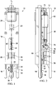
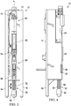
- the device 10 includes longitudinal axis A 1 , a frame 12, one or more legs extending away from the frame, a control system 80, a linear actuator 60 coupled to the frame 12 and coupled to the control system, a gripper 56 coupled to the linear actuator, and a load cell 70 coupled to the linear actuator.
- "Couple” and “coupled”, as used herein, means a physical connection or coupling and/or an operative connection or coupling (e.g., electrical connection or coupling or wireless connection or coupling).
- the frame 12 may include any variety of shapes, sizes, configurations, and components. It may comprise multiple components releaseably or fixedly coupled to each other or a single, integral unit. In the embodiment shown, the frame 12 includes a substantially U-shaped configuration.
- the device 10 may include a first plate 18 and a second plate 20 coupled o the frame 12.
- the first plate 18 may include a first opening 22 disposed therein.
- the second plate 20 may include a second opening 24 and an aperture 26 disposed therein.
- the first plate 18 and/or the second plate 20 may include a leg extension indicator 40.
- the leg extension indicator 40 may include indicia 42 marked along the aperture 26, identifying a distance one of the legs of the device 10 has been extended or retracted as will be described more fully herein below.
- the frame 12 includes a first leg 14, a second leg 16, and a third leg 30 coupled to and extending from the frame 12.
- the legs may be spaced-apart from each other.
- the first, second, and third legs 14, 16, and 30, respectively, may be integrally coupled to the frame 12, releaseably coupled to the frame 12, or some combination thereof.
- the first, second, and third legs 14, 16, and 30, respectively are spaced-apart approximately 60 degrees from each other about the longitudinal axis A 1 such that the legs form a tripod configuration.
- one or more of the legs may be movable relative to the frame 12.
- the first leg 14, second leg 16, and/or third leg 30 may be movable relative to the frame. Referring back to the embodiment illustrated in FIGS. 1-4 , the first and second legs 14 and 16, respectively, are integral to the frame 12.
- the third leg 30 is movably coupled to the frame 12. As configured, the third leg 30 moves linearly substantially parallel to the longitudinal axis A 1 in two opposite directions relative to the frame 12 as indicated by arrow (A). In other words, the leg 30 may protract (extend) from the frame 12 or retract (draw in) toward the frame 12.
- the third leg 30 comprises a rod 32 having external threads 34 and an end 39 distal to the frame 12.
- the device 10 includes a knob 36 rotatably coupled to the frame 12.
- the knob 36 may be accessible through the first opening 22.
- the knob 36 includes internal threads (not shown) that are configured to receive the rod 32 and engage the external threads 34 of the rod.
- the knob 36 may be rotated in the counterclockwise direction to protract (extend) the distal end 39 of the third leg 30 away from the frame 12 (e.g., downward) and in the clockwise direction to retract (draw in) the distal end 39 of the leg 30 toward the frame 12 (e.g., upward) or vice versa.
- the third leg 30 has an adjustable length relative the first and second legs 14 and 16, respectively, and also relative to the frame 12. This permits the three legs to be positioned upon a curved surface such as, for example, a subject's head, and still maintain the device 10 and thus the linear actuator 60 substantially normal (e.g., perpendicular) to the surface (e.g., head, scalp, etc.) or to enable the device 10 to be positioned upon a surface (e.g., a flat surface) and orient the device relative to that surface and/or a hair follicle to obtain a desired pull angle relative to the surface and/or hair follicle.
- This adjustability enables the device to be oriented to pull a strand of hair at different angles relative to the surface the device is placed upon and/or the hair follicle that the strand of hair is extending from.
- the device 10 may include any number of legs such as, for example, five (5) legs, positioned in any number of configurations such as, for example, pentagonal-shaped.
- the device 10 may include one fixed leg and one movable or adjustable leg. It is also understood that any number of the legs may be movably coupled to the frame 12 similar to leg 30 above or by other mechanisms and methods as conventionally known or yet-to-be developed.
- the device 10 includes a control system 80.
- the control system 80 may be integrated into and positioned within the frame 12 or remote from the frame 12.
- a conventional signal and data cable 72 may connect the control system 80 to the linear actuator 60.
- the control system 80 may be embodied as any type of computing device or server or capable of processing, communicating, storing, maintaining, and transferring data.
- control system 80 may be embodied as a server, a microcomputer, a minicomputer, a mainframe, a desktop computer, a laptop computer, a mobile computing device, a handheld computer, a smart phone, a tablet computer, a personal digital assistant, a telephony device, a custom chip, an embedded processing device, linear actuator control board, or other computing device and/or suitable programmable device.
- control system 80 can be embodied as a computing device integrated with other systems or subsystems.
- the control system 80 includes a linear actuator control board such as, for example, those commercially available from Firgelli automation.
- the control system 80 includes a processor 82. It can also comprise a system bus 84, a memory 86, a data storage 88, and communication circuitry 90. In certain embodiments, the control system 80 may further include one or more peripheral devices. Of course, the control system 80 may include other or additional components, such as those commonly found in a server and/or computer (e.g., various input/output devices), in other embodiments. Additionally, in certain embodiments, one or more of the illustrative components may be incorporated in, or otherwise from a portion of, another component. For example, the memory 86, or portions thereof, can be incorporated in the processor 82 in some embodiments.
- control system 80 may include other components, subcomponents, and devices commonly found in a computer and/or computing device, which are not illustrated in FIG. 5 for clarity of the description. Also, it should be appreciated that any one of the illustrative components of the control system 80 set forth above may be eliminated from the system.
- the processor 82 can be embodied as any type of processor capable of performing the functions described herein.
- the processor 82 can be embodied as a single or multicore processor, a digital signal processor, microcontroller, a general purpose central processing unit (CPU), a reduced instruction set computer (RISC) processor, a processor having a pipeline, a complex instruction set computer (CISC) processor, an application specific integrated circuit (ASIC), a programmable logic device (PLD), a field programmable gate array (FPGA), or other processor or processing/controlling circuit or controller.
- CPU central processing unit
- RISC reduced instruction set computer
- CISC complex instruction set computer
- ASIC application specific integrated circuit
- PLD programmable logic device
- FPGA field programmable gate array
- the control system 80 includes a system bus 84 for interconnecting the various components of the control system 80.
- the system bus 84 may be embodied as, or otherwise include, memory controller hubs, input/output control hubs, firmware devices, communication links (i.e., point-to-point links, bus links, wires, cables, light guides, printed circuit board traces, etc.) and/or other components and subsystems to facilitate the input/output operations with the processor 82, the memory 86, and other components of the control system 80.
- the control system 80 may be integrated into one or more chips such as a programmable logic device or an application specific integrated circuit (ASIC).
- the system bus 84 can form a portion of a system-on-a-chip (SoC) and be incorporated, along with the processor 82, the memory 86, and other components of the control system 80, on a single integrated circuit chip.
- SoC system-on-a-chip
- the memory 86 may be embodied as any type of volatile or non-volatile memory or data storage capable of performing the functions described herein.
- the memory 86 may be embodied as read only memory (ROM), random access memory (RAM), cache memory associated with the processor 82, or other memories such as dynamic RAM (DRAM), static ram (SRAM), programmable ROM (PROM), electrically erasable PROM (EEPROM), flash memory, a removable memory card or disk, a solid state drive, and so forth.
- the memory 86 may store various data and software used during operation of the control system 80 such as operating systems, applications, programs, libraries, drivers, and a plurality of pulling profiles as will be described below herein.
- the data storage 88 may be embodied as any type of device or devices configured for short-term or long-term storage of data such as, for example, memory devices and circuits, memory cards, hard disk drives, solid-state drives, or other data storage devices.
- the data storage 88 includes storage media such as a storage device that can be configured to have multiple modules, such as magnetic disk drives, floppy drives, tape drives, hard drives, optical drives and media, magneto-optical drives and media, compact disc drives, Compact Disc Read Only Memory (CD-ROM), Compact Disc Recordable (CD-R), Compact Disc Rewriteable (CD-RW), a suitable type of Digital Versatile Disc (DVD) or Blu-Ray disc, and so forth.
- CD-ROM Compact Disc Read Only Memory
- CD-R Compact Disc Recordable
- CD-RW Compact Disc Rewriteable
- DVD Digital Versatile Disc
- Blu-Ray disc and so forth.
- Storage media such as flash drives, solid state hard drives, redundant array of individual disks (RAID), virtual drives, networked drives and other memory means including storage media on the processor 82, or the memory 86 are also contemplated as storage devices. It should be appreciated that such memory may be internal or external with respect to operation of the disclosed embodiments. It should also be appreciated that certain portions of the processes described herein can be performed using instructions (including a plurality of pulling profiles) stored on a computer-readable medium or media that direct or otherwise instruct a computer system to perform the process steps.
- Non-transitory computer-readable media comprises all computer-readable media except for transitory, propagating signals.
- the data storage device 88 may be configured to store a plurality of pulling profiles of the control system 80.
- the communication circuitry 90 of the control system 80 may be embodied as any type of communication circuit, device, interface, or collection thereof, capable of enabling communications between the control system 80 and the linear actuator 60 of the device 10, a remote computer 110, and/or any other computing device communicatively coupled thereto.
- the communication circuitry 90 may be embodied as one or more network interface controllers (NICs), in certain embodiments.
- NICs network interface controllers
- the communication circuitry 112 may be configured to use any one or more communication technologies (e.g., wireless or wired communications) and associated protocols (e.g., Ethernet, Wi-Fi®, WiMAX, etc.) to effect such communication.
- control system 80, remote computer 110, and/or any other computing devices can communicate with each other over one or more networks.
- the network(s) may be embodied as any number of various wired and/or wireless communication networks.
- the network(s) may be embodied as or otherwise include a local area network (LAN), a wide area network (WAN), a cellular network, or a publicly-accessible, global network such as the Internet.
- the network(s) may include any number of additional devices to facilitate communication between the computing devices of the system 100.
- some or all of the control system 80 and remote computer 110 are installed and operate local to a computing device.
- the control system 80 comprises a linear actuator control board constructed to control a linear actuator. Additionally, in certain embodiments, the control system 80 may further include one or more peripheral devices. Such peripheral devices may include any type of peripheral device commonly found in a computing device such as additional data storage, memory, a hardware keyboard, a keypad, a gesture or graphical input device, a motion input device, a touchscreen interface, one or more displays, an audio unit, a voice recognition unit, a vibratory device, a computer mouse, a peripheral communication device, and any other suitable user interface, input/output device, and/or other peripheral device.
- peripheral devices may include any type of peripheral device commonly found in a computing device such as additional data storage, memory, a hardware keyboard, a keypad, a gesture or graphical input device, a motion input device, a touchscreen interface, one or more displays, an audio unit, a voice recognition unit, a vibratory device, a computer mouse, a peripheral communication device, and any other suitable user interface, input/output device, and/or other peripheral device.
- the memory 86 includes a plurality of pulling profiles.
- a pulling profile includes a set of instructions for execution by the processor 82 in controlling the linear actuator 60 while pulling one or more strands of hair.
- the pulling profile may define the magnitude of pull force, threshold pull force, pull velocity, pull distance, pull time, pull force over time, pull frequency, amount of time between pulls, whether a static or constant pull force is maintained during the breaks between pulls with increasing pull force, any combination thereof, and/or any other characteristics or properties.
- the memory 86 may include a plurality of pulling profiles, wherein a second one of the plurality of pulling profiles differs from a first one of the plurality of pulling profiles in at least any one of the following: threshold pull force, pull distance, pull time, pull force over time, pull velocity, pull frequency, amount of time between pulls, or whether a static or constant pull force is maintained during the breaks between pulls with increasing pull force.
- the plurality of pulling profiles stored in memory of the control system 80 may include one or more of the following pulling profile instructions set forth below. In certain embodiments, the plurality of profiles stored in memory of the control system 80 may include at least any two of the pulling profile instructions set forth below.
- One example of a pulling profile instruction may be stored in memory and executed by the processor may include a pulling profile instruction to cause a gripped strand of hair to be pulled toward the frame at a constant force and speed until the gripped a strand of hair either breaks or releases from a follicle.
- a pulling profile instruction may include a pulling profile instruction to cause a gripped strand of hair to be pulled toward the frame with an increasing force at a constant speed for at least a first distance (X 1 ), then hold the gripped a strand of hair under a constant pull force for a first time period (T 1 ) at that distance (X 1 ), then cause the linear actuator to repeat the previous steps n number of times or until the gripped a strand of hair either breaks or releases from a follicle.
- a pulling profile instruction may include a pulling profile instruction to cause a gripped strand of hair to be pulled toward the frame with an increasing force at a constant speed for at least a first distance (X 1 ), then remove the pulling force from the gripped strand of hair for a first time period (T 1 ), then cause the linear actuator to repeat the previous steps n number of times or until the gripped a strand of hair either breaks or releases from a follicle.
- a pulling profile instruction may include a pulling profile instruction to cause a gripped strand of hair to be pulled toward the frame with an increasing force at a constant speed for at least a first distance (X 1 ), then hold the gripped strand of hair under a constant pull force for a first time period (T 1 ) at that distance (X 1 ), then remove the pulling force from the strand of hair for a second time period (T 2 ), then cause the linear actuator to repeat the previous steps n number of times or until the gripped strand of hair either breaks or releases from a follicle.
- a pulling profile instruction may include a pulling profile instruction to cause a gripped strand of hair to be pulled toward the frame with an increasing force at a constant speed until a predetermined pulling force is reached (e.g., a threshold pulling force), then remove the pulling force from the strand of hair for a first time period (T 1 ), then cause the linear actuator to repeat the previous steps n number of times or until the gripped strand of hair either breaks or releases from a follicle.
- a predetermined pulling force e.g., a threshold pulling force
- a pulling profile instruction may include a pulling profile instruction to cause a gripped strand of hair to be pulled toward the frame with an increasing force at a constant speed until a threshold pulling force is reached, then hold the gripped strand of hair under a constant pull force for a first time period (T 1 ) at that threshold pulling force, then remove the pulling force from the strand of hair for a second time period (T 2 ), then cause the linear actuator to repeat the previous steps n number of times or until the gripped strand of hair either breaks or releases from a follicle.
- the linear actuator 60 includes a proximal end 62 and a distal end 64.
- the linear actuator 60 may include a clip bracket 66 coupled at the distal end 64.
- the clip bracket 66 may be constructed to releaseably receive and/or engage the gripper 56.
- the clip bracket 66 may include a receiver 68 constructed to releaseably engage an end of the gripper 56.
- the linear actuator 60 in certain embodiments, may be coaxially aligned with the longitudinal axis A 1 .
- the linear actuator may include an electrical linear actuator such as, for example, linear actuators commercially available from Firgelli Automations, L16-P.
- the linear actuator may be sized in accordance with the length of stroke and force required for the desired task.
- the linear actuator may be powered by an AC or DC power source 80 (e.g., one or more batteries). It should be understood that other actuators may be used such as, for example, pneumatic and hydraulic actuators.
- the device 10 includes a gripper 56 coupled to the distal end 64 of the linear actuator.
- the gripper 56 may include a flanged end 58 that is constructed to releaseably insert into and/or engage the receiver 68 of the clip bracket 66.
- the gripper 56 may include a micro-grabber such as, for example, a micro-grabber commercially available from DigiKey, Pamona-4233 micro-grabber.
- the gripper may include, but not be limited to, alligator clips, robotic grippers, spring clips, manual vice grips, combinations thereof, etc.
- the gripper may be manually operated to open and close to grip and/or release one or more strands of hair.
- the gripper may be coupled to the control system 80 which may send control signals to the gripper, causing it to open and close in order to grip and/or release one or more strands of hair.
- the device includes the load cell 70 coupled to the linear actuator 60.
- the load cell 70 is positioned between an upper portion and a lower portion of the actuator.
- the opposed forces i.e., the force created by the retracting linear actuator and the opposite force created by the strand of hair connected within the follicle
- the load cell 70 may include a strain gauge such as, for example, LCL-005, commercially available by Omega®.
- the load cell has an excitation of 5 Vdc, 12V max., rated output of 2 mV/V +/- 20%, zero balance of 0.3 mV/V, combined error of 0.25% FS, operating temperature of -54 to 93° C (-65 to 200° F), compensated temperature of -7 to 49° C (20 to 120° F), temperature effects of (zero balance of 0.02% FS/°F and output of 0.02%/°F), resistance (input and output) of 1200 +/- 300 ⁇ , insulation resistance of 1000 ⁇ @ 50 Vdc, seal of urethane coated, safe overload of 150% FS, full scale deflection of 0.25 to 1.27 mm (0.010 to 0.050 in.), lead wire of 9 in. shielded PVC 4-conductor 30AWG, and material of >816 gf (2lb): 301 SS; ⁇ 816 gf (2lb) beryllium copper.
- the load cell 70 may be coupled to a remote computer 110 and/or the control system 80.
- the remote computer 110 may include one or more networks (e.g., LAN, WAN, Internet, etc.) such that the load cell 70 may send strain and/or force data measured by it to the remote computer 110, control system 80, and/or other networks to store, manipulate, analyze, compare, transfer to other computers or networks, and/or the like.
- the remote computer 110 may include any and/or all of the components that the control system 80 may include and perform the same or similar functions as set forth above.
- the load cell 70 may be connected to the remote computer 110, the control system 80, and/or other networks (e.g., a WAN, Internet, etc.) via wired (e.g., signal and/or data cable 74) or wireless connections such as, those set forth above and/or conventionally known.
- the load cell 70 and/or the device 10 are coupled to the remote computer 110 via a USB wired connection.
- the device 10 may further include a strain gauge to USB converter coupled between the load cell 70 and the USB wired connection.
- the load cell 70, control system 80, remote computer 110, and/or other sensors coupled to the device may be configured to measure, calculate, and/or store a variety of pulling data.
- Pulling data may include, but not be limited to, pulling force (e.g., strain), pulling force over-time (e.g., strain over-time), pulling velocity (e.g., velocity of the linear actuator), pulling time, and/or other similar measurement data.
- Pulling time may include, but not be limited to the period of time from the point in time wherein the linear actuator begins pulling a strand of hair to the point in time that either the linear actuator stops pulling the strand of hair or the strand of hair releases from its follicle.
- Pulling time may also include the cumulative amount of time for multiple pulls with such as, defined in one or more of the pulling profile instructions set forth herein.
- the pulling time may be calculated manually, macros, or via software by dividing the pulling velocity by the total distance traveled.
- the velocity may be measured via a sensor coupled to the device and/or control system 80.
- the device 10 may measure the pulling force every 10 ms and the distance traveled by the linear actuator. From this data, software on the control system 80 may calculate pull velocity (mm/ms).
- the device 10 may include a potentiometer to determine pulling velocity. The information from the potentiometer is conditioned and/or translated into the data used by the control system to determine and/or calculate velocity.
- the power source 100 may be coupled to the device 10 and/or the control system 80 to provide power to any of the individual components and/or the device as a whole.
- the power source 100 may be an A/C and/or DC.
- the A/C source may be a conventional 120 volt A/C outlet.
- the DC source may include one or more batteries.
- the device 10 may be used in a variety of ways and methods in a variety of environments, including, but not limited to in a laboratory, testing facility, at home, in a retail store, and/or other locations. Referring to FIG. 6 , one example of a method that the device 10 may be used in includes a method of testing hair or skin properties.
- the method includes setting a first leg and second leg of a hair plucking device upon a surface; orienting the hair plucking device relative to the surface to provide a desired pull angle; gripping, by a gripper, a strand of hair of a subject; activating a control system comprising a plurality of pulling profile instructions stored in memory, wherein upon activation of the control system, the control system executes a selected one of a plurality of pulling profile instructions, and wherein a non-selected one of the plurality of pulling profile instructions differs from the selected one of the plurality of pulling profile instructions in at least any one of the following: threshold pull force, pull distance, pull time, pull force over time, threshold pull force, pull distance, pull velocity, pull frequency, amount of time between pulls, or whether a static or constant pull force is maintained during the breaks between pulls with increasing pull force, pull frequency, amount of time between pulls, or whether a static or constant pull force is maintained during the breaks between pulls with increasing pull force, pull frequency, amount of time between pulls,
- the plurality of pulling profile instructions may include at least two of the following pulling profile instructions: a first pulling profile instruction to cause a gripped strand of hair to be pulled toward the frame at a constant force and speed until the gripped a strand of hair either breaks or releases from a follicle; a second pulling profile instruction to cause a gripped strand of hair to be pulled toward the frame with an increasing force at a constant speed for at least a first distance (X1), then hold the gripped a strand of hair under a constant pull force for a first time period (T1) at that distance (X1), then cause the linear actuator to repeat the previous steps n number of times or until the gripped a strand of hair either breaks or releases from a follicle; a third pulling profile instruction to cause a gripped strand of hair to be pulled toward the frame with an increasing force at a constant speed for at least a first distance (X1), then remove the pulling force from the gripped strand of hair for a first time period (T1)
- the step of orienting the hair plucking device to provide the desired pull angle may include adjusting the length of at least one of the first and second legs.
- the method may include communicating wirelessly between the control system and the linear actuator.
- the method may further include orienting a hair plucking device relative to a surface to provide a desired pull angle of a strand of hair of the subject post application of a consumer product to the subjects hair or scalp; gripping, by a gripper, the strand of hair of the subject; activating a control system, wherein upon activation of the control system, the control system executes another selected one of a plurality of pulling profile instruction stored in memory, wherein a non-selected one of the plurality of pulling profile instructions differs from the another selected one of the plurality of pulling profile instructions in at least any one of the following: threshold pull force, pull distance, pull time, pull force over time, pull velocity, pull frequency, amount of time between pulls, or whether a static or constant pull force is maintained during the
- each step and/or method may be repeated multiple times for several strands of hair from a single subject and/or may be repeated multiple times to pull a single strand of hair from each of multiple subjects or several strands of hair from each of multiple subjects.
- the method may further include compiling pulling data for one or more strands of hair prior to application of a consumer product to the one or more strands of hair or a scalp of one or more subjects. In certain embodiments, the method may further include compiling pulling data for one or more strands of hair post application of the consumer product to the one or more strands of hair or the scalp of the one or more subjects. In certain embodiments, the method may further include supporting a product claim for the consumer product with this compiled data.
- the device 10 may be used at a retail store or point of sale to perform a hair pluck test, demonstration, and/or one or more of the methods shown and described herein.
Landscapes
- Health & Medical Sciences (AREA)
- Life Sciences & Earth Sciences (AREA)
- Medical Informatics (AREA)
- Biophysics (AREA)
- Pathology (AREA)
- Engineering & Computer Science (AREA)
- Biomedical Technology (AREA)
- Heart & Thoracic Surgery (AREA)
- Physics & Mathematics (AREA)
- Molecular Biology (AREA)
- Surgery (AREA)
- Animal Behavior & Ethology (AREA)
- General Health & Medical Sciences (AREA)
- Public Health (AREA)
- Veterinary Medicine (AREA)
- Dermatology (AREA)
- Cosmetics (AREA)
- Surgical Instruments (AREA)
- Orthopedics, Nursing, And Contraception (AREA)
Claims (9)
- Vorrichtung (10), die dafür konstruiert ist, um eine Haarsträhne zu ziehen, wobei die Vorrichtung (10) umfasst:einen Rahmen (12) mit einer Längsachse (A1) und einem ersten Ende; ein erstes Standbein (14), ein zweites Standbein (16) und ein drittes Standbein (30), die sich von dem ersten Ende des Rahmens (12) erstrecken, wobei das dritte Standbein von dem ersten und zweiten Standbein beabstandet ist; wobei das erste, zweite und dritte Standbein (14, 16 und 30) jeweils integral mit dem Rahmen (12) gekoppelt sind oder lösbar mit dem Rahmen (12) gekoppelt sind, oder eine Kombination davon;wobei das dritte Standbein (30) in Bezug zu dem Rahmen (12) linear beweglich ist;wobei das dritte Standbein (30) eine Stange (32) mit Außengewinden (34) und ein Ende (39) distal zu dem Rahmen (12) umfasst, wobei die Vorrichtung (10) einen Knopf (36) einschließt, der drehbar mit dem Rahmen (12) gekoppelt ist, wobei der Knopf (36) Innengewinde einschließt, die dafür konfiguriert sind, um die Stange (32) aufzunehmen und die Außengewinde (34) der Stange (32) in Eingriff zu bringen;ein Steuersystem (80), das einen Prozessor (82) umfasst, um eine Vielzahl von in einem Speicher (86) gespeicherten Ziehprofilanweisungen auszuführen;ein lineares Betätigungselement (60), das mit dem Steuersystem (80) funktional gekoppelt und dafür konstruiert ist, um sich linear entlang der Längsachse (A1) in Bezug zu dem Rahmen (12) zu bewegen, wobei das lineare Betätigungselement (60) ein distales Ende (64) aufweist;eine mit dem linearen Betätigungselement (60) gekoppelte Lastzelle (70), wobei die Lastzelle (70) zwischen einem oberen Abschnitt und einem unteren Abschnitt des Betätigungselements (60) positioniert ist; undein mit dem distalen Ende (64) des linearen Betätigungselements (60) gekoppeltes Greifelement (56), wobei das Greifelement (56) dafür konstruiert ist, um eine Haarsträhne zu greifen;wobei, wenn eine oder mehrere der Vielzahl von im Speicher (86) gespeicherten Ziehprofilanweisungen durch den Prozessor (82) ausgeführt werden, das Steuersystem (80) das lineare Betätigungselement (60) dazu veranlasst, entlang der Längsachse (A1) unter Ausüben einer Ziehkraft auf eine durch das Greifelement (56) gegriffene Haarsträhne zurückzufahren; undwobei die Lastzelle (70) dafür konfiguriert ist, um die Ziehkraft zu messen.
- Vorrichtung (10) nach Anspruch 1, ferner umfassend eine mit dem linearen Betätigungselement (60) gekoppelte Energiequelle (100), wobei die Energiequelle (100) ausgewählt ist aus der Gruppe bestehend aus den Folgenden: elektrisch, hydraulisch und pneumatisch.
- Vorrichtung (10) nach einem der vorstehenden Ansprüche, wobei die Lastzelle (70) ein Belastungsmessgerät ist.
- Vorrichtung (10) nach einem der vorstehenden Ansprüche, wobei die Vielzahl von im Speicher (86) gespeicherten Ziehprofilanweisungen eine erste Ziehprofilanweisung und eine zweite Ziehprofilanweisung einschließen, wobei sich die zweite Ziehprofilanweisung von der ersten Ziehprofilanweisung in mindestens einem beliebigen der Folgenden unterscheidet: Schwellenwertziehkraft, Ziehdistanz, Ziehzeit, Ziehkraft in Bezug zur Zeit, Ziehgeschwindigkeit, Ziehhäufigkeit, Zeitspanne zwischen Zügen, oder ob eine statische oder konstante Ziehkraft während der Pausen zwischen den Zügen bei zunehmender Ziehkraft beibehalten wird.
- Verfahren zum Prüfen von Haar- oder Hauteigenschaften, wobei die Vorrichtung (10) nach den Ansprüchen 1-3 verwendet wird in den Schritten:Aufstellen eines ersten Standbeins (14) und zweiten Standbeins (16) einer Haarzupfvorrichtung auf eine Kopfoberfläche einer Testperson,und ein mit dem Rahmen (12) gekoppeltes und sich von diesem erstreckendes drittes Standbein (30), und voneinander beabstandet sind; wobei das erste, zweite und dritte Standbein (14, 16 und 30) jeweils integral mit dem Rahmen (12) gekoppelt sind oder lösbar mit dem Rahmen (12) gekoppelt sind, oder eine Kombination davon;wobei das dritte Standbein (30) in Bezug zu dem Rahmen (12) linear beweglich ist;wobei das dritte Standbein (30) eine Stange (32) mit Außengewinden (34) und ein Ende (39) distal zu dem Rahmen (12) umfasst, wobei die Vorrichtung (10) einen Knopf (36) einschließt, der drehbar mit dem Rahmen (12) gekoppelt ist, wobei der Knopf (36) Innengewinde einschließt, die dafür konfiguriert sind, um die Stange (32) aufzunehmen und die Außengewinde (34) der Stange (32) in Eingriff zu bringen;Ausrichten der Haarzupfvorrichtung in Bezug zu der Kopfoberfläche der Testperson, um einen gewünschten Ziehwinkel bereitzustellen;Greifen, durch ein Greifelement (56), einer Haarsträhne einer Testperson; undAktivieren eines Steuersystems (80), umfassend eine Vielzahl von im Speicher (86) gespeicherten Ziehprofilanweisungen, wobei das Steuersystem (80) bei Aktivierung des Steuersystems (80) eine aus einer Vielzahl von Ziehprofilanweisungen ausgewählte ausführt und wobei eine nicht aus der Vielzahl von Ziehprofilanweisungen ausgewählte sich von der aus der Vielzahl von Ziehprofilanweisungen ausgewählten in mindestens einem beliebigen der Folgenden unterscheidet: Schwellenwertziehkraft, Ziehdistanz, Ziehzeit, Ziehkraft in Bezug zur Zeit, Ziehgeschwindigkeit, Ziehhäufigkeit, Zeitspanne zwischen Zügen, oder ob eine statische oder konstante Ziehkraft während der Pausen zwischen den Zügen mit zunehmender Ziehkraft beibehalten wird;Zurückfahren, durch das Steuersystem (80), eines linearen Betätigungselements (60) in Übereinstimmung mit der ausgewählten einen der Vielzahl von Ziehprofilanweisungen, um eine Ziehkraft an die Haarsträhne anzulegen; undMessen, durch eine mit dem Betätigungselement (60) gekoppelten Lastzelle (70), der Ziehkraft.
- Verfahren nach Anspruch 5, wobei die Vielzahl von Ziehprofilanweisungen mindestens zwei der folgenden Ziehprofilanweisungen einschließt:eine erste Ziehprofilanweisung, die veranlasst, dass eine gegriffene Haarsträhne mit einer konstanten Kraft und Tempo in Richtung des Rahmens (12) gezogen wird, bis die gegriffene Haarsträhne entweder reißt oder aus einem Follikel gelöst wird;eine zweite Ziehprofilanweisung, die veranlasst, dass eine gegriffene Haarsträhne mit einer zunehmenden Kraft bei einem konstanten Tempo für mindestens eine erste Distanz (X1) in Richtung des Rahmens (12) gezogen wird, anschließend die gegriffene eine Haarsträhne unter einer konstanten Ziehkraft für eine erste Zeitdauer (T1) bei dieser Distanz (X1) gehalten wird, anschließend das lineare Betätigungselement (60) veranlasst wird, die vorherigen Schritte n-Male zu wiederholen oder bis die gegriffene eine Haarsträhne entweder reißt oder aus einem Follikel gelöst wird;eine dritte Ziehprofilanweisung, die veranlasst, dass eine gegriffene Haarsträhne mit einer zunehmenden Kraft bei einem konstanten Tempo für mindestens eine erste Distanz (X1) in Richtung des Rahmens (12) gezogen wird, anschließend die Ziehkraft von der gegriffenen Haarsträhne für eine erste Zeitdauer (T1) entfernt wird, anschließend das lineare Betätigungselement (60) veranlasst wird, die vorherigen Schritte n-Male zu wiederholen oder bis die gegriffene eine Haarsträhne entweder reißt oder aus einem Follikel gelöst wird;eine vierte Ziehprofilanweisung, die veranlasst, dass eine gegriffene Haarsträhne mit einer zunehmenden Kraft bei einem konstanten Tempo für mindestens eine erste Distanz (X1) in Richtung des Rahmens (12) gezogen wird, anschließend die gegriffene Haarsträhne unter einer konstanten Ziehkraft für eine erste Zeitdauer (T1) bei dieser Distanz (X1) gehalten wird, anschließend die Ziehkraft für eine zweite Zeitdauer (T2) von der Haarsträhne entfernt wird, anschließend das lineare Betätigungselement (60) veranlasst wird, die vorherigen Schritte n-Male zu wiederholen oder bis die gegriffene eine Haarsträhne entweder reißt oder aus einem Follikel gelöst wird;eine fünfte Ziehprofilanweisung, die veranlasst, dass eine gegriffene Haarsträhne mit einer zunehmenden Kraft bei einem konstanten Tempo in Richtung des Rahmens (12) gezogen wird, bis eine vorher festgelegte Ziehkraft (z. B. eine Schwellenwertziehkraft) erreicht ist, anschließend die Ziehkraft von der gegriffenen Haarsträhne für eine erste Zeitdauer (T1) entfernt wird, anschließend das lineare Betätigungselement (60) veranlasst wird, die vorherigen Schritte n-Male zu wiederholen oder bis die gegriffene eine Haarsträhne entweder reißt oder aus einem Follikel gelöst wird; odereine sechste Ziehprofilanweisung, die veranlasst, dass eine gegriffene Haarsträhne mit einer zunehmenden Kraft bei einem konstanten Tempo in Richtung des Rahmens (12) gezogen wird, bis eine Schwellenwertzugkraft erreicht ist, anschließend die gegriffene Haarsträhne unter einer konstanten Ziehkraft für eine erste Zeitdauer (T1) bei dieser Schwellenwertkraft gehalten wird, anschließend die Ziehkraft für eine zweite Zeitdauer (T2) von der Haarsträhne entfernt wird, anschließend das lineare Betätigungselement (60) veranlasst wird, die vorherigen Schritte n-Male zu wiederholen oder bis die gegriffene eine Haarsträhne entweder reißt oder aus einem Follikel gelöst wird.
- Verfahren nach Ansprüchen 5-6, wobei das Ausrichten der Haarzupfvorrichtung, um den gewünschten Ziehwinkel bereitzustellen, das Einstellen der Länge von mindestens einem des ersten und zweiten Standbeins (14, 16) umfasst.
- Verfahren nach Ansprüchen 5-7, ferner umfassend:Ausrichten einer Haarzupfvorrichtung in Bezug zu einer Kopfoberfläche einer Testperson, um einen gewünschten Ziehwinkel einer Haarsträhne der Testperson nach der Anwendung eines Verbraucherprodukts auf die Haare oder Kopfhaut der Testperson bereitzustellen;Greifen, durch ein Greifelement (56), der Haarsträhne einer Testperson;Aktivieren eines Steuersystems (80), wobei das Steuersystem (80) bei Aktivierung des Steuersystems (80) eine andere aus einer Vielzahl von im Speicher (86) gespeicherten Ziehprofilanweisungen ausgewähltes ausführt, wobei eine nicht aus der Vielzahl von Ziehprofilanweisungen ausgewählte sich von der anderen aus der Vielzahl von Ziehprofilanweisungen ausgewählten in mindestens einem beliebigen der Folgenden unterscheidet: Schwellenwertziehkraft, Ziehdistanz, Ziehzeit, Ziehkraft in Bezug zur Zeit, Ziehgeschwindigkeit, Ziehhäufigkeit, Zeitspanne zwischen Zügen, oder ob eine statische oder konstante Ziehkraft während der Pausen zwischen den Zügen mit zunehmender Ziehkraft beibehalten wird;Zurückfahren, durch das Steuersystem (80), eines linearen Betätigungselements (60) in Übereinstimmung mit der anderen ausgewählten einen der Vielzahl von Ziehprofilanweisungen, um eine Ziehkraft an die Haarsträhne anzulegen; undMessen, durch eine mit dem Betätigungselement (60) gekoppelten Lastzelle (70), der Ziehkraft.
- Verfahren nach Anspruch 8, ferner umfassend das Erheben von Ziehdaten für eine Haarsträhne vor Anwendung eines Verbraucherprodukts auf Haar oder Kopfhaut einer Testperson; Erheben von Ziehdaten für eine Haarsträhne nach Anwendung des Verbraucherprodukts auf Haar oder die Kopfhaut der Testperson; und Unterstützen eines Produktanspruchs für das Verbraucherprodukt mit diesen erhobenen Daten.
Applications Claiming Priority (2)
| Application Number | Priority Date | Filing Date | Title |
|---|---|---|---|
| US201662432845P | 2016-12-12 | 2016-12-12 | |
| PCT/US2017/065541 WO2018111748A1 (en) | 2016-12-12 | 2017-12-11 | An apparatus and method for pulling a strand of hair |
Publications (2)
| Publication Number | Publication Date |
|---|---|
| EP3551006A1 EP3551006A1 (de) | 2019-10-16 |
| EP3551006B1 true EP3551006B1 (de) | 2020-09-16 |
Family
ID=60935972
Family Applications (1)
| Application Number | Title | Priority Date | Filing Date |
|---|---|---|---|
| EP17825686.3A Active EP3551006B1 (de) | 2016-12-12 | 2017-12-11 | Vorrichtung und verfahren zum ziehen einer haarsträhne |
Country Status (4)
| Country | Link |
|---|---|
| US (1) | US10736398B2 (de) |
| EP (1) | EP3551006B1 (de) |
| CN (1) | CN110072409B (de) |
| WO (1) | WO2018111748A1 (de) |
Family Cites Families (31)
| Publication number | Priority date | Publication date | Assignee | Title |
|---|---|---|---|---|
| CH353846A (fr) | 1957-03-28 | 1961-04-30 | Noeel Miles Henri | Dispositif indicateur du point de rupture des cheveux |
| US4185106A (en) | 1972-07-11 | 1980-01-22 | Hoechst Aktiengesellschaft | Pyridones as antidandruff agents |
| JPS5655857A (en) | 1979-10-15 | 1981-05-16 | Sharp Corp | Diagnosing device for quality of hair |
| JPS5810630A (ja) | 1981-07-11 | 1983-01-21 | Toyo Seiki Seisakusho:Kk | 皮膚、毛髪等生体物質の力学的性質の測定方法及びその装置 |
| JPS58165035A (ja) | 1982-03-25 | 1983-09-30 | Sharp Corp | 毛髪の強さ診断装置 |
| LU86944A1 (fr) | 1987-07-17 | 1989-03-08 | Oreal | Composition a base de derives d'hydroxypyridone pour diminuer la chute des cheveux |
| JPH03152439A (ja) | 1989-11-08 | 1991-06-28 | Hiroyoshi Nagamitsu | 毛髪測定装置 |
| US5424435A (en) | 1993-10-18 | 1995-06-13 | Olin Corporation | 1-hydroxy-6-substituted-2-pyridones |
| GB9607568D0 (en) | 1996-04-12 | 1996-06-12 | Unilever Plc | Antimicrobial hair treatment composition |
| US5792961A (en) * | 1997-04-10 | 1998-08-11 | Giebner Enterprises, Inc. | Portable motorized fastener tester |
| JP2001172159A (ja) | 1999-12-20 | 2001-06-26 | Lion Corp | 低刺激性抗菌化粧料 |
| CN2517292Y (zh) * | 2001-11-08 | 2002-10-23 | 方明杭 | 发辫成形器 |
| US7131208B2 (en) * | 2004-04-16 | 2006-11-07 | Bernard Cohen Technology, Llc | Method, device and cartridge for measuring fluctuations in the cross-sectional area of hair in a pre-determined scalp area |
| JP2008007476A (ja) | 2006-06-30 | 2008-01-17 | Lion Corp | 育毛養毛剤組成物 |
| JP4356783B2 (ja) * | 2007-03-01 | 2009-11-04 | ソニー株式会社 | 毛から生体物質を抽出する方法及び該方法に用いる毛採取器具 |
| CN101317712A (zh) * | 2007-06-09 | 2008-12-10 | 超人集团有限公司 | 电动拔毛器 |
| JP2009096777A (ja) | 2007-10-19 | 2009-05-07 | Lion Corp | 育毛養毛剤組成物 |
| JP2009137889A (ja) | 2007-12-06 | 2009-06-25 | Lion Corp | 育毛養毛剤、育毛養毛用組成物および育毛養毛方法 |
| EP2245956B1 (de) * | 2009-04-27 | 2012-06-20 | Braun GmbH | Hybrid-Epilationsvorrichtung |
| EP2429530B1 (de) | 2009-05-14 | 2018-11-07 | The General Hospital Corporation | (s)-meclozin zur behandlung von ischämischen reperfusions-schäden |
| FR2949052B1 (fr) | 2009-08-13 | 2015-03-27 | Oreal | Procede de traitement cosmetique du cuir chevelu. |
| IL201884A0 (en) | 2009-11-02 | 2010-06-30 | Cupron Corp | Hair care compositions and materials |
| US20120003300A1 (en) | 2010-06-30 | 2012-01-05 | Pangaea Laboratories Ltd | Composition Comprising Vascular Endothelial Growth Factor (VEGF) for the Treatment of Hair Loss |
| EP2627309A2 (de) | 2010-10-15 | 2013-08-21 | The Procter and Gamble Company | Verwendung von monoaminoxidasehemmern für verbesserte epithelbiologie |
| US8980876B2 (en) | 2010-10-28 | 2015-03-17 | The Procter & Gamble Company | Inhibition of microbial growth by aconitase inhibition |
| US20130109664A1 (en) | 2011-10-28 | 2013-05-02 | James Robert Schwartz | Personal Care Compositions Comprising a Pyrithione and an Iron Chelator |
| NZ705751A (en) | 2012-08-16 | 2018-04-27 | Gencor Armats Biotek Pvt Ltd | Herbal preparation for stimulation of hair growth, control of hair fall, dandruff and infections thereof using ageratum spp. |
| CN104640476A (zh) * | 2012-09-17 | 2015-05-20 | 皇家飞利浦有限公司 | 脱毛设备 |
| WO2014095289A2 (en) | 2012-12-20 | 2014-06-26 | Unilever Plc | Method of treating hair ageing |
| WO2017189946A1 (en) | 2016-04-29 | 2017-11-02 | The Procter & Gamble Company | Method of treating a hair disorder with n-hydroxypyridinones |
| CN106108344B (zh) * | 2016-08-22 | 2018-10-26 | 吴让攀 | 一种拔毛器 |
-
2017
- 2017-12-08 US US15/836,377 patent/US10736398B2/en not_active Expired - Fee Related
- 2017-12-11 CN CN201780076849.9A patent/CN110072409B/zh not_active Expired - Fee Related
- 2017-12-11 EP EP17825686.3A patent/EP3551006B1/de active Active
- 2017-12-11 WO PCT/US2017/065541 patent/WO2018111748A1/en not_active Ceased
Non-Patent Citations (1)
| Title |
|---|
| None * |
Also Published As
| Publication number | Publication date |
|---|---|
| US20180160788A1 (en) | 2018-06-14 |
| WO2018111748A1 (en) | 2018-06-21 |
| CN110072409A (zh) | 2019-07-30 |
| CN110072409B (zh) | 2022-02-01 |
| US10736398B2 (en) | 2020-08-11 |
| EP3551006A1 (de) | 2019-10-16 |
Similar Documents
| Publication | Publication Date | Title |
|---|---|---|
| CN107969120B (zh) | 考虑周围接触的机器人的致动器的控制和调节 | |
| CN105956315A (zh) | 一种可进行疲劳裂纹扩展速率估算和寿命预测的方法 | |
| US11119015B2 (en) | Determination of dynamic parameters for adaptive actuator control | |
| Dagalakis et al. | Human-robot collaboration dynamic impact testing and calibration instrument for disposable robot safety artifacts | |
| EP3551006B1 (de) | Vorrichtung und verfahren zum ziehen einer haarsträhne | |
| CN111168569B (zh) | 一种磨削材料去除量预测方法、装置、设备及存储介质 | |
| Rezazadeh et al. | Workspace analysis of multibody cable-driven mechanisms | |
| CN104483214A (zh) | 一种分布式传感光缆疲劳性能测试装置 | |
| US9983116B2 (en) | Testing a peel force of an adhesive medium | |
| Pott | On the limitations on the lower and upper tensions for cable-driven parallel robots | |
| CN203643264U (zh) | 一种钢绞线最大力伸长率测量装置 | |
| CN205691426U (zh) | 一种用于检测复合绝缘子端部金具压接质量的系统 | |
| CN116294954A (zh) | 导体应变评价方法及装置、电缆寿命预测方法 | |
| CN211235337U (zh) | 一种电缆反复弯曲试验机 | |
| CN104483219A (zh) | 材料疲劳过程综合测试系统 | |
| CN104077444A (zh) | 一种压痕数据分析方法 | |
| Zhao et al. | A cable-driven grasper with decoupled motion and forces | |
| US11493414B2 (en) | Testing system for flexible sample in electronics having a retractable holder configured to conform a sample by a mandrel | |
| CN205234565U (zh) | 血管夹不同张口度处夹力的简易测定装置 | |
| Nassar et al. | Bigsid: bionic grasping with edge-ai slip detection | |
| Dal Santo et al. | Cold forming by stretching of aeronautic sheet metal parts | |
| ES2985681T3 (es) | Métodos y aparatos para controlar la preparación de los especímenes de prueba | |
| CN202420974U (zh) | 微机控制电子拉力机 | |
| KR102890070B1 (ko) | 열전도율 기반 물체 인식 장치 및 방법 | |
| Kowalewski et al. | Experimental and numerical investigations of the effects associated to complex loading combinations |
Legal Events
| Date | Code | Title | Description |
|---|---|---|---|
| STAA | Information on the status of an ep patent application or granted ep patent |
Free format text: STATUS: UNKNOWN |
|
| STAA | Information on the status of an ep patent application or granted ep patent |
Free format text: STATUS: THE INTERNATIONAL PUBLICATION HAS BEEN MADE |
|
| PUAI | Public reference made under article 153(3) epc to a published international application that has entered the european phase |
Free format text: ORIGINAL CODE: 0009012 |
|
| STAA | Information on the status of an ep patent application or granted ep patent |
Free format text: STATUS: REQUEST FOR EXAMINATION WAS MADE |
|
| 17P | Request for examination filed |
Effective date: 20190604 |
|
| AK | Designated contracting states |
Kind code of ref document: A1 Designated state(s): AL AT BE BG CH CY CZ DE DK EE ES FI FR GB GR HR HU IE IS IT LI LT LU LV MC MK MT NL NO PL PT RO RS SE SI SK SM TR |
|
| AX | Request for extension of the european patent |
Extension state: BA ME |
|
| DAV | Request for validation of the european patent (deleted) | ||
| DAX | Request for extension of the european patent (deleted) | ||
| GRAJ | Information related to disapproval of communication of intention to grant by the applicant or resumption of examination proceedings by the epo deleted |
Free format text: ORIGINAL CODE: EPIDOSDIGR1 |
|
| STAA | Information on the status of an ep patent application or granted ep patent |
Free format text: STATUS: GRANT OF PATENT IS INTENDED |
|
| GRAP | Despatch of communication of intention to grant a patent |
Free format text: ORIGINAL CODE: EPIDOSNIGR1 |
|
| INTG | Intention to grant announced |
Effective date: 20200414 |
|
| GRAS | Grant fee paid |
Free format text: ORIGINAL CODE: EPIDOSNIGR3 |
|
| GRAA | (expected) grant |
Free format text: ORIGINAL CODE: 0009210 |
|
| STAA | Information on the status of an ep patent application or granted ep patent |
Free format text: STATUS: THE PATENT HAS BEEN GRANTED |
|
| AK | Designated contracting states |
Kind code of ref document: B1 Designated state(s): AL AT BE BG CH CY CZ DE DK EE ES FI FR GB GR HR HU IE IS IT LI LT LU LV MC MK MT NL NO PL PT RO RS SE SI SK SM TR |
|
| REG | Reference to a national code |
Ref country code: GB Ref legal event code: FG4D |
|
| REG | Reference to a national code |
Ref country code: CH Ref legal event code: EP |
|
| REG | Reference to a national code |
Ref country code: DE Ref legal event code: R096 Ref document number: 602017023901 Country of ref document: DE |
|
| REG | Reference to a national code |
Ref country code: IE Ref legal event code: FG4D |
|
| REG | Reference to a national code |
Ref country code: AT Ref legal event code: REF Ref document number: 1313318 Country of ref document: AT Kind code of ref document: T Effective date: 20201015 |
|
| PG25 | Lapsed in a contracting state [announced via postgrant information from national office to epo] |
Ref country code: HR Free format text: LAPSE BECAUSE OF FAILURE TO SUBMIT A TRANSLATION OF THE DESCRIPTION OR TO PAY THE FEE WITHIN THE PRESCRIBED TIME-LIMIT Effective date: 20200916 Ref country code: BG Free format text: LAPSE BECAUSE OF FAILURE TO SUBMIT A TRANSLATION OF THE DESCRIPTION OR TO PAY THE FEE WITHIN THE PRESCRIBED TIME-LIMIT Effective date: 20201216 Ref country code: GR Free format text: LAPSE BECAUSE OF FAILURE TO SUBMIT A TRANSLATION OF THE DESCRIPTION OR TO PAY THE FEE WITHIN THE PRESCRIBED TIME-LIMIT Effective date: 20201217 Ref country code: NO Free format text: LAPSE BECAUSE OF FAILURE TO SUBMIT A TRANSLATION OF THE DESCRIPTION OR TO PAY THE FEE WITHIN THE PRESCRIBED TIME-LIMIT Effective date: 20201216 Ref country code: FI Free format text: LAPSE BECAUSE OF FAILURE TO SUBMIT A TRANSLATION OF THE DESCRIPTION OR TO PAY THE FEE WITHIN THE PRESCRIBED TIME-LIMIT Effective date: 20200916 Ref country code: SE Free format text: LAPSE BECAUSE OF FAILURE TO SUBMIT A TRANSLATION OF THE DESCRIPTION OR TO PAY THE FEE WITHIN THE PRESCRIBED TIME-LIMIT Effective date: 20200916 |
|
| REG | Reference to a national code |
Ref country code: AT Ref legal event code: MK05 Ref document number: 1313318 Country of ref document: AT Kind code of ref document: T Effective date: 20200916 |
|
| REG | Reference to a national code |
Ref country code: NL Ref legal event code: MP Effective date: 20200916 |
|
| PG25 | Lapsed in a contracting state [announced via postgrant information from national office to epo] |
Ref country code: LV Free format text: LAPSE BECAUSE OF FAILURE TO SUBMIT A TRANSLATION OF THE DESCRIPTION OR TO PAY THE FEE WITHIN THE PRESCRIBED TIME-LIMIT Effective date: 20200916 Ref country code: RS Free format text: LAPSE BECAUSE OF FAILURE TO SUBMIT A TRANSLATION OF THE DESCRIPTION OR TO PAY THE FEE WITHIN THE PRESCRIBED TIME-LIMIT Effective date: 20200916 |
|
| REG | Reference to a national code |
Ref country code: LT Ref legal event code: MG4D |
|
| PG25 | Lapsed in a contracting state [announced via postgrant information from national office to epo] |
Ref country code: SM Free format text: LAPSE BECAUSE OF FAILURE TO SUBMIT A TRANSLATION OF THE DESCRIPTION OR TO PAY THE FEE WITHIN THE PRESCRIBED TIME-LIMIT Effective date: 20200916 Ref country code: LT Free format text: LAPSE BECAUSE OF FAILURE TO SUBMIT A TRANSLATION OF THE DESCRIPTION OR TO PAY THE FEE WITHIN THE PRESCRIBED TIME-LIMIT Effective date: 20200916 Ref country code: CZ Free format text: LAPSE BECAUSE OF FAILURE TO SUBMIT A TRANSLATION OF THE DESCRIPTION OR TO PAY THE FEE WITHIN THE PRESCRIBED TIME-LIMIT Effective date: 20200916 Ref country code: RO Free format text: LAPSE BECAUSE OF FAILURE TO SUBMIT A TRANSLATION OF THE DESCRIPTION OR TO PAY THE FEE WITHIN THE PRESCRIBED TIME-LIMIT Effective date: 20200916 Ref country code: PT Free format text: LAPSE BECAUSE OF FAILURE TO SUBMIT A TRANSLATION OF THE DESCRIPTION OR TO PAY THE FEE WITHIN THE PRESCRIBED TIME-LIMIT Effective date: 20210118 Ref country code: EE Free format text: LAPSE BECAUSE OF FAILURE TO SUBMIT A TRANSLATION OF THE DESCRIPTION OR TO PAY THE FEE WITHIN THE PRESCRIBED TIME-LIMIT Effective date: 20200916 |
|
| PG25 | Lapsed in a contracting state [announced via postgrant information from national office to epo] |
Ref country code: PL Free format text: LAPSE BECAUSE OF FAILURE TO SUBMIT A TRANSLATION OF THE DESCRIPTION OR TO PAY THE FEE WITHIN THE PRESCRIBED TIME-LIMIT Effective date: 20200916 Ref country code: IS Free format text: LAPSE BECAUSE OF FAILURE TO SUBMIT A TRANSLATION OF THE DESCRIPTION OR TO PAY THE FEE WITHIN THE PRESCRIBED TIME-LIMIT Effective date: 20210116 Ref country code: AL Free format text: LAPSE BECAUSE OF FAILURE TO SUBMIT A TRANSLATION OF THE DESCRIPTION OR TO PAY THE FEE WITHIN THE PRESCRIBED TIME-LIMIT Effective date: 20200916 Ref country code: AT Free format text: LAPSE BECAUSE OF FAILURE TO SUBMIT A TRANSLATION OF THE DESCRIPTION OR TO PAY THE FEE WITHIN THE PRESCRIBED TIME-LIMIT Effective date: 20200916 Ref country code: ES Free format text: LAPSE BECAUSE OF FAILURE TO SUBMIT A TRANSLATION OF THE DESCRIPTION OR TO PAY THE FEE WITHIN THE PRESCRIBED TIME-LIMIT Effective date: 20200916 |
|
| REG | Reference to a national code |
Ref country code: DE Ref legal event code: R097 Ref document number: 602017023901 Country of ref document: DE |
|
| PG25 | Lapsed in a contracting state [announced via postgrant information from national office to epo] |
Ref country code: SK Free format text: LAPSE BECAUSE OF FAILURE TO SUBMIT A TRANSLATION OF THE DESCRIPTION OR TO PAY THE FEE WITHIN THE PRESCRIBED TIME-LIMIT Effective date: 20200916 |
|
| PLBE | No opposition filed within time limit |
Free format text: ORIGINAL CODE: 0009261 |
|
| STAA | Information on the status of an ep patent application or granted ep patent |
Free format text: STATUS: NO OPPOSITION FILED WITHIN TIME LIMIT |
|
| REG | Reference to a national code |
Ref country code: CH Ref legal event code: PL |
|
| 26N | No opposition filed |
Effective date: 20210617 |
|
| PG25 | Lapsed in a contracting state [announced via postgrant information from national office to epo] |
Ref country code: SI Free format text: LAPSE BECAUSE OF FAILURE TO SUBMIT A TRANSLATION OF THE DESCRIPTION OR TO PAY THE FEE WITHIN THE PRESCRIBED TIME-LIMIT Effective date: 20200916 Ref country code: DK Free format text: LAPSE BECAUSE OF FAILURE TO SUBMIT A TRANSLATION OF THE DESCRIPTION OR TO PAY THE FEE WITHIN THE PRESCRIBED TIME-LIMIT Effective date: 20200916 Ref country code: MC Free format text: LAPSE BECAUSE OF FAILURE TO SUBMIT A TRANSLATION OF THE DESCRIPTION OR TO PAY THE FEE WITHIN THE PRESCRIBED TIME-LIMIT Effective date: 20200916 |
|
| REG | Reference to a national code |
Ref country code: BE Ref legal event code: MM Effective date: 20201231 |
|
| PG25 | Lapsed in a contracting state [announced via postgrant information from national office to epo] |
Ref country code: IE Free format text: LAPSE BECAUSE OF NON-PAYMENT OF DUE FEES Effective date: 20201211 Ref country code: FR Free format text: LAPSE BECAUSE OF NON-PAYMENT OF DUE FEES Effective date: 20201231 Ref country code: IT Free format text: LAPSE BECAUSE OF FAILURE TO SUBMIT A TRANSLATION OF THE DESCRIPTION OR TO PAY THE FEE WITHIN THE PRESCRIBED TIME-LIMIT Effective date: 20200916 Ref country code: LU Free format text: LAPSE BECAUSE OF NON-PAYMENT OF DUE FEES Effective date: 20201211 |
|
| PG25 | Lapsed in a contracting state [announced via postgrant information from national office to epo] |
Ref country code: CH Free format text: LAPSE BECAUSE OF NON-PAYMENT OF DUE FEES Effective date: 20201231 Ref country code: LI Free format text: LAPSE BECAUSE OF NON-PAYMENT OF DUE FEES Effective date: 20201231 |
|
| PGFP | Annual fee paid to national office [announced via postgrant information from national office to epo] |
Ref country code: GB Payment date: 20211104 Year of fee payment: 5 Ref country code: DE Payment date: 20211102 Year of fee payment: 5 |
|
| PG25 | Lapsed in a contracting state [announced via postgrant information from national office to epo] |
Ref country code: TR Free format text: LAPSE BECAUSE OF FAILURE TO SUBMIT A TRANSLATION OF THE DESCRIPTION OR TO PAY THE FEE WITHIN THE PRESCRIBED TIME-LIMIT Effective date: 20200916 Ref country code: MT Free format text: LAPSE BECAUSE OF FAILURE TO SUBMIT A TRANSLATION OF THE DESCRIPTION OR TO PAY THE FEE WITHIN THE PRESCRIBED TIME-LIMIT Effective date: 20200916 Ref country code: CY Free format text: LAPSE BECAUSE OF FAILURE TO SUBMIT A TRANSLATION OF THE DESCRIPTION OR TO PAY THE FEE WITHIN THE PRESCRIBED TIME-LIMIT Effective date: 20200916 |
|
| PG25 | Lapsed in a contracting state [announced via postgrant information from national office to epo] |
Ref country code: MK Free format text: LAPSE BECAUSE OF FAILURE TO SUBMIT A TRANSLATION OF THE DESCRIPTION OR TO PAY THE FEE WITHIN THE PRESCRIBED TIME-LIMIT Effective date: 20200916 |
|
| PG25 | Lapsed in a contracting state [announced via postgrant information from national office to epo] |
Ref country code: BE Free format text: LAPSE BECAUSE OF NON-PAYMENT OF DUE FEES Effective date: 20201231 |
|
| PG25 | Lapsed in a contracting state [announced via postgrant information from national office to epo] |
Ref country code: NL Free format text: LAPSE BECAUSE OF NON-PAYMENT OF DUE FEES Effective date: 20200923 |
|
| REG | Reference to a national code |
Ref country code: DE Ref legal event code: R119 Ref document number: 602017023901 Country of ref document: DE |
|
| GBPC | Gb: european patent ceased through non-payment of renewal fee |
Effective date: 20221211 |
|
| PG25 | Lapsed in a contracting state [announced via postgrant information from national office to epo] |
Ref country code: GB Free format text: LAPSE BECAUSE OF NON-PAYMENT OF DUE FEES Effective date: 20221211 Ref country code: DE Free format text: LAPSE BECAUSE OF NON-PAYMENT OF DUE FEES Effective date: 20230701 |