EP3549816B1 - Lösevorrichtung für einen hochvoltstecker - Google Patents
Lösevorrichtung für einen hochvoltstecker Download PDFInfo
- Publication number
- EP3549816B1 EP3549816B1 EP19162479.0A EP19162479A EP3549816B1 EP 3549816 B1 EP3549816 B1 EP 3549816B1 EP 19162479 A EP19162479 A EP 19162479A EP 3549816 B1 EP3549816 B1 EP 3549816B1
- Authority
- EP
- European Patent Office
- Prior art keywords
- housing
- voltage
- detacher
- detacher according
- locking
- Prior art date
- Legal status (The legal status is an assumption and is not a legal conclusion. Google has not performed a legal analysis and makes no representation as to the accuracy of the status listed.)
- Active
Links
Images

Classifications
-
- B—PERFORMING OPERATIONS; TRANSPORTING
- B60—VEHICLES IN GENERAL
- B60L—PROPULSION OF ELECTRICALLY-PROPELLED VEHICLES; SUPPLYING ELECTRIC POWER FOR AUXILIARY EQUIPMENT OF ELECTRICALLY-PROPELLED VEHICLES; ELECTRODYNAMIC BRAKE SYSTEMS FOR VEHICLES IN GENERAL; MAGNETIC SUSPENSION OR LEVITATION FOR VEHICLES; MONITORING OPERATING VARIABLES OF ELECTRICALLY-PROPELLED VEHICLES; ELECTRIC SAFETY DEVICES FOR ELECTRICALLY-PROPELLED VEHICLES
- B60L55/00—Arrangements for supplying energy stored within a vehicle to a power network, i.e. vehicle-to-grid [V2G] arrangements
-
- B—PERFORMING OPERATIONS; TRANSPORTING
- B25—HAND TOOLS; PORTABLE POWER-DRIVEN TOOLS; MANIPULATORS
- B25B—TOOLS OR BENCH DEVICES NOT OTHERWISE PROVIDED FOR, FOR FASTENING, CONNECTING, DISENGAGING, OR HOLDING
- B25B27/00—Hand tools, specially adapted for fitting together or separating parts or objects whether or not involving some deformation, not otherwise provided for
- B25B27/0035—Hand tools, specially adapted for fitting together or separating parts or objects whether or not involving some deformation, not otherwise provided for for motor-vehicles
-
- B—PERFORMING OPERATIONS; TRANSPORTING
- B25—HAND TOOLS; PORTABLE POWER-DRIVEN TOOLS; MANIPULATORS
- B25B—TOOLS OR BENCH DEVICES NOT OTHERWISE PROVIDED FOR, FOR FASTENING, CONNECTING, DISENGAGING, OR HOLDING
- B25B27/00—Hand tools, specially adapted for fitting together or separating parts or objects whether or not involving some deformation, not otherwise provided for
- B25B27/02—Hand tools, specially adapted for fitting together or separating parts or objects whether or not involving some deformation, not otherwise provided for for connecting objects by press fit or detaching same
-
- B—PERFORMING OPERATIONS; TRANSPORTING
- B60—VEHICLES IN GENERAL
- B60L—PROPULSION OF ELECTRICALLY-PROPELLED VEHICLES; SUPPLYING ELECTRIC POWER FOR AUXILIARY EQUIPMENT OF ELECTRICALLY-PROPELLED VEHICLES; ELECTRODYNAMIC BRAKE SYSTEMS FOR VEHICLES IN GENERAL; MAGNETIC SUSPENSION OR LEVITATION FOR VEHICLES; MONITORING OPERATING VARIABLES OF ELECTRICALLY-PROPELLED VEHICLES; ELECTRIC SAFETY DEVICES FOR ELECTRICALLY-PROPELLED VEHICLES
- B60L53/00—Methods of charging batteries, specially adapted for electric vehicles; Charging stations or on-board charging equipment therefor; Exchange of energy storage elements in electric vehicles
- B60L53/10—Methods of charging batteries, specially adapted for electric vehicles; Charging stations or on-board charging equipment therefor; Exchange of energy storage elements in electric vehicles characterised by the energy transfer between the charging station and the vehicle
- B60L53/14—Conductive energy transfer
- B60L53/16—Connectors, e.g. plugs or sockets, specially adapted for charging electric vehicles
-
- H—ELECTRICITY
- H01—ELECTRIC ELEMENTS
- H01R—ELECTRICALLY-CONDUCTIVE CONNECTIONS; STRUCTURAL ASSOCIATIONS OF A PLURALITY OF MUTUALLY-INSULATED ELECTRICAL CONNECTING ELEMENTS; COUPLING DEVICES; CURRENT COLLECTORS
- H01R13/00—Details of coupling devices of the kinds covered by groups H01R12/70 or H01R24/00 - H01R33/00
- H01R13/62—Means for facilitating engagement or disengagement of coupling parts or for holding them in engagement
- H01R13/629—Additional means for facilitating engagement or disengagement of coupling parts, e.g. aligning or guiding means, levers, gas pressure electrical locking indicators, manufacturing tolerances
- H01R13/633—Additional means for facilitating engagement or disengagement of coupling parts, e.g. aligning or guiding means, levers, gas pressure electrical locking indicators, manufacturing tolerances for disengagement only
-
- H—ELECTRICITY
- H01—ELECTRIC ELEMENTS
- H01R—ELECTRICALLY-CONDUCTIVE CONNECTIONS; STRUCTURAL ASSOCIATIONS OF A PLURALITY OF MUTUALLY-INSULATED ELECTRICAL CONNECTING ELEMENTS; COUPLING DEVICES; CURRENT COLLECTORS
- H01R43/00—Apparatus or processes specially adapted for manufacturing, assembling, maintaining, or repairing of line connectors or current collectors or for joining electric conductors
- H01R43/26—Apparatus or processes specially adapted for manufacturing, assembling, maintaining, or repairing of line connectors or current collectors or for joining electric conductors for engaging or disengaging the two parts of a coupling device
-
- Y—GENERAL TAGGING OF NEW TECHNOLOGICAL DEVELOPMENTS; GENERAL TAGGING OF CROSS-SECTIONAL TECHNOLOGIES SPANNING OVER SEVERAL SECTIONS OF THE IPC; TECHNICAL SUBJECTS COVERED BY FORMER USPC CROSS-REFERENCE ART COLLECTIONS [XRACs] AND DIGESTS
- Y02—TECHNOLOGIES OR APPLICATIONS FOR MITIGATION OR ADAPTATION AGAINST CLIMATE CHANGE
- Y02E—REDUCTION OF GREENHOUSE GAS [GHG] EMISSIONS, RELATED TO ENERGY GENERATION, TRANSMISSION OR DISTRIBUTION
- Y02E60/00—Enabling technologies; Technologies with a potential or indirect contribution to GHG emissions mitigation
-
- Y—GENERAL TAGGING OF NEW TECHNOLOGICAL DEVELOPMENTS; GENERAL TAGGING OF CROSS-SECTIONAL TECHNOLOGIES SPANNING OVER SEVERAL SECTIONS OF THE IPC; TECHNICAL SUBJECTS COVERED BY FORMER USPC CROSS-REFERENCE ART COLLECTIONS [XRACs] AND DIGESTS
- Y02—TECHNOLOGIES OR APPLICATIONS FOR MITIGATION OR ADAPTATION AGAINST CLIMATE CHANGE
- Y02T—CLIMATE CHANGE MITIGATION TECHNOLOGIES RELATED TO TRANSPORTATION
- Y02T10/00—Road transport of goods or passengers
- Y02T10/60—Other road transportation technologies with climate change mitigation effect
- Y02T10/70—Energy storage systems for electromobility, e.g. batteries
-
- Y—GENERAL TAGGING OF NEW TECHNOLOGICAL DEVELOPMENTS; GENERAL TAGGING OF CROSS-SECTIONAL TECHNOLOGIES SPANNING OVER SEVERAL SECTIONS OF THE IPC; TECHNICAL SUBJECTS COVERED BY FORMER USPC CROSS-REFERENCE ART COLLECTIONS [XRACs] AND DIGESTS
- Y02—TECHNOLOGIES OR APPLICATIONS FOR MITIGATION OR ADAPTATION AGAINST CLIMATE CHANGE
- Y02T—CLIMATE CHANGE MITIGATION TECHNOLOGIES RELATED TO TRANSPORTATION
- Y02T10/00—Road transport of goods or passengers
- Y02T10/60—Other road transportation technologies with climate change mitigation effect
- Y02T10/7072—Electromobility specific charging systems or methods for batteries, ultracapacitors, supercapacitors or double-layer capacitors
-
- Y—GENERAL TAGGING OF NEW TECHNOLOGICAL DEVELOPMENTS; GENERAL TAGGING OF CROSS-SECTIONAL TECHNOLOGIES SPANNING OVER SEVERAL SECTIONS OF THE IPC; TECHNICAL SUBJECTS COVERED BY FORMER USPC CROSS-REFERENCE ART COLLECTIONS [XRACs] AND DIGESTS
- Y02—TECHNOLOGIES OR APPLICATIONS FOR MITIGATION OR ADAPTATION AGAINST CLIMATE CHANGE
- Y02T—CLIMATE CHANGE MITIGATION TECHNOLOGIES RELATED TO TRANSPORTATION
- Y02T90/00—Enabling technologies or technologies with a potential or indirect contribution to GHG emissions mitigation
- Y02T90/10—Technologies relating to charging of electric vehicles
- Y02T90/14—Plug-in electric vehicles
-
- Y—GENERAL TAGGING OF NEW TECHNOLOGICAL DEVELOPMENTS; GENERAL TAGGING OF CROSS-SECTIONAL TECHNOLOGIES SPANNING OVER SEVERAL SECTIONS OF THE IPC; TECHNICAL SUBJECTS COVERED BY FORMER USPC CROSS-REFERENCE ART COLLECTIONS [XRACs] AND DIGESTS
- Y04—INFORMATION OR COMMUNICATION TECHNOLOGIES HAVING AN IMPACT ON OTHER TECHNOLOGY AREAS
- Y04S—SYSTEMS INTEGRATING TECHNOLOGIES RELATED TO POWER NETWORK OPERATION, COMMUNICATION OR INFORMATION TECHNOLOGIES FOR IMPROVING THE ELECTRICAL POWER GENERATION, TRANSMISSION, DISTRIBUTION, MANAGEMENT OR USAGE, i.e. SMART GRIDS
- Y04S10/00—Systems supporting electrical power generation, transmission or distribution
- Y04S10/12—Monitoring or controlling equipment for energy generation units, e.g. distributed energy generation [DER] or load-side generation
- Y04S10/126—Monitoring or controlling equipment for energy generation units, e.g. distributed energy generation [DER] or load-side generation the energy generation units being or involving electric vehicles [EV] or hybrid vehicles [HEV], i.e. power aggregation of EV or HEV, vehicle to grid arrangements [V2G]
Definitions
- the invention relates to a release device for a high-voltage plug.
- Electric partial or full drives are increasingly being provided in modern motor vehicles, which include corresponding energy stores in the form of batteries, mostly in the form of lithium-ion batteries. These batteries deliver voltages of several hundred volts. Due to the high voltage level, these batteries are usually also called high-voltage batteries; the voltages are in voltage class B.
- high-voltage plug connections are used, usually comprising a plug on a cable and a socket provided on the battery side.
- Such a high-voltage plug or such a high-voltage plug connection is secured with various locks so that such a high-voltage plug cannot be unplugged from such a high-voltage component to which a corresponding voltage level is applied, either accidentally or due to carelessness on the part of the user or a technician.
- a widely used high-voltage plug with the type designation HVA 280 is installed in modern motor vehicles. Another example of such a high-voltage connector is from US2012/108106 refer to.
- HVA 280 plug At the access point to the high-voltage system in order to de-energize it, ie to take it out of service.
- This plug connection must be removed for all work on the high-voltage system, which is why this HVA 280 plug at the access point for the high-voltage system is the high-voltage plug that is most frequently unplugged and plugged in in the vehicle. Release devices are state-of-the-art, as in US2013/012051 disclosed, known, but can only be used for a specific type of high-voltage connectors.
- the HVA 280 high-voltage connector has three corresponding locking elements, namely a tab to be pulled along the connector's longitudinal axis, a first locking button or locking tab that can be released by pressing, and a second locking button or locking tab that can also be released by pressing. These locks are provided in different longitudinal positions on the high-voltage connector.
- the first locking element in the form of the tab that is to be pulled lengthwise must first be released, then the first button or the first tab must be pressed, after which the high-voltage plug can be pulled a short distance out of the high-voltage socket, which interrupts the so-called pilot line, consequently so the circuit is opened.
- the high-voltage plug can only be completely removed from the high-voltage socket of the high-voltage component by then pressing the second tab or the second button.
- This connector is often mounted in the vehicle in places that are very difficult to access because z. B. by other components or due to the positioning in the vehicle, easy access is not possible or a situation is given, which is very difficult to reach by hand. Even if the high-voltage plug can be reached by hand, the release often cannot be actuated due to the installation position.
- the invention is therefore based on the problem of specifying a possibility for simply removing a high-voltage plug.
- a release device for such a high-voltage connector which is locked via two or more locking elements on a surrounding structure, comprising a housing designed for releasable placement on the plugged locked high-voltage connector and two or more actuating elements, which are attached to the housing, can be actuated by the user and can be coupled to the locking elements for mechanically releasing the locking elements from their locking position.
- the user or technician can use a release device according to the invention to release the high-voltage plug, which has a housing that can be detachably placed on the high-voltage plug.
- a release device which has a housing that can be detachably placed on the high-voltage plug.
- actuating means which can be operated or actuated by the user or technician and which can be or are mechanically coupled to corresponding locking elements of the high-voltage plug when the release device is in the attached position. By actuating these actuating means, the locking elements are actuated and mechanically released from their locking position.
- the housing is correspondingly elongated, so that the user or technician can actuate the corresponding actuating means at positions that are sufficiently far away from the actual locking elements on the high-voltage plug, so that it is not necessary to reach into the immediate area with the hand to grab the locking elements, which, as described in the introduction, is sometimes not possible or only possible with great difficulty.
- the actuating means are ultimately designed in such a way that they bridge the distance from an actuating position at which the individual actuating means can be actuated by the user or technician to the mechanical coupling of the respective actuating means to the locking element on the connector side.
- the user or technician only has to place the housing on the high-voltage connector. He can then bring the individual locking elements out of their locking position from an easily accessible position remote from the plug by actuating the actuating means and loosen the plug and finally pull it off.
- the housing itself can have two housing halves which are pivotably linked to one another and which can be connected to one another in the working position placed on the high-voltage plug. So it is designed as a clamshell case.
- cooperating snap or latching elements can be provided on both housing halves in the working position, which on the one hand allow a sufficiently firm fixation on the high-voltage plug, but on the other hand can also be released again relatively easily.
- the housing is designed in one piece and is open at the side, so that it can be pushed onto the high-voltage plug from the side. In this way, too, a simple arrangement of the housing or the release device can take place on the high-voltage plug.
- the actuating means can be purely mechanical actuating means. Depending on the configuration or the number of locking elements of the high-voltage plug, at least two actuating means, possibly more actuating means, can be provided, so three actuating means would be provided in the case of the HVA 280 high-voltage plug.
- An actuating means can be a pure traction means that can be coupled to a locking element to be pulled in the working position.
- the first locking element is a corresponding pull strap that can be actuated via the mechanical pulling means.
- the one or more additional actuating means are pressure means, which can be coupled in the working position to a locking element that is to be pressed.
- the HVA 280 high-voltage connector has two separate tabs or buttons to press.
- a corresponding actuating means in the form of a pressure means is assigned to each tab or button, which can be coupled to a locking element to be pressed in the working position.
- the pulling means can easily be embodied in the form of an elongate pull tab
- the pressing means require an appropriate mechanical design in order to exert sufficient pressure on the respective tab or button provided on the connector side.
- the pressure means it is conceivable for the pressure means to be in the form of a lever mechanism, at least comprising an actuating lever to be actuated manually and a pressure lever which interacts with the locking element. This lever mechanism makes it possible to move a pressure lever from a remote location by manually actuating the actuating lever in such a way that it exerts sufficient pressure on the respective locking element.
- the release device is therefore a purely manual-mechanical release device.
- actuating means electrically, that is to say that electrical actuating means are provided.
- electrical actuation means are provided.
- several electrical actuation means are used; in the case of an HVA 280 high-voltage plug, three such electrical actuation means would have to be provided.
- These actuating means expediently each comprise a small electric motor, via which an actuating element which interacts with the respective locking element can be actuated. This actuating element is moved via the electric motor in the corresponding manner that is required to release the respective locking element. If the locking element is a tab that is to be pulled, then the associated actuating element is moved accordingly via the electric motor or is coupled to the locking tab in such a way that it is pulled. If the locking element is a depressing tab or a button, the actuating element is also moved accordingly via the electric motor or is coupled to the locking element in such a way that sufficient pressure can be built up.
- corresponding pushbutton or switching elements are provided on the housing at correspondingly distant positions, which can be easily actuated by the user due to their positioning on the outside of the housing.
- the corresponding button or switching element is pressed, the corresponding electric motor is activated, the corresponding actuating element is moved and the corresponding locking element on the connector side is released.
- the release device In order to enable the operation of the electric motors, it is conceivable for the release device to be connected to a corresponding power supply via a connecting cable.
- the release device is provided with an energy store provided on or in the housing in the form of a battery or an accumulator, which is expediently exchangeable.
- the release device can work completely independently, a cable connection to a corresponding power and voltage supply is not required.
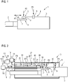
- the high-voltage plug 1 shows a high-voltage connector 1 of the HVA 280 type, which is arranged on a high-voltage cable 2 .
- the high-voltage plug 1 has a plug housing 3 in which, not shown in detail, corresponding electrical connection means such as contact pins or contact sockets, etc., which are electrically connected to the high-voltage cable 2, are arranged.
- the high-voltage plug 1 To contact the high-voltage plug 1 with a device to be connected, the high-voltage plug 1 is plugged with its housing 3 into a corresponding connection socket and mechanically locked there.
- three locking elements 4, 5, 6 are provided on the connector housing 3, each of which defines three separate locking planes in which a mechanical locking to corresponding locking elements on the socket is effected.
- the first locking element 4 is designed as a tab 7 which, as indicated by the arrow P1, is to be pulled axially in order to release the unlocking.
- the second locking element 5 is designed as a tab 8 to be pressed, which is to be pressed in the direction of the arrow P2 for unlocking.
- the third locking element 6 is designed as a push button 9, which is also to be pressed for unlocking, as shown by the arrow P3.
- the locking elements 4, 5, 6 are to be actuated in sequence, that is to say that the tab 7 is to be pulled first, after which the pressure tab 8 is to be pressed. This causes the closed line connection to open, which means that there is electrical decoupling from the socket, but nonetheless given a mechanical locking via the third locking element 6. So only when the push button 9 is pressed is the high-voltage plug 1 unlocked and can be pulled out of the socket.
- a release device 10 is provided according to the invention, as is shown in a first embodiment of the invention in 2 is shown.
- the release device 10 is attached here to the high-voltage plug 1, it sits partially on the housing 3, but also partially overlaps the high-voltage cable 2.
- the release device 10 has a housing 11, preferably made of plastic.
- This housing 11 comprises, for example, two housing halves which are pivotably coupled to one another via a film hinge or the like, so that the housing 11 can be opened up and placed around the high-voltage plug 1 in the open state. In order to bring it into the assembly position, the housing halves are pivoted together, ie the housing 11 is closed. The closed position can be fixed using appropriate locking elements or a locking clip or the like.
- the release device 10 has three actuating means 12, 13, 14 which can be coupled to the respective locking elements 4, 5, 6 and which serve to mechanically release the respective locking.
- mechanical actuating means 12, 13, 14 are provided which can be actuated manually by the user, but from a position which is sufficiently distant from the mounting position of the locking elements 4, 5, 6.
- the mechanical actuating means 12 is designed as a traction means 15 . It has a corresponding driver 16 which acts on the tab 7 .
- the driver 16 is connected to a pull tab 17 which is connected to a handle portion 18 for the user to grip and pull.
- the pull tab 17 is guided in a corresponding guide 19 inside the housing. The user pulls on the handling section 18, see arrow P4, the tab 7 is released from its locked position.
- the mechanical actuating means 13 is designed as a pressure means 20 and comprises a lever mechanism 21.
- a rigid pressure lever 22 can be pivoted about a pivot point 23.
- the pressure lever 22 has an actuating section 24 at the end, with which it presses on the pressure tab 8 in the assembly position.
- a handling portion 25 is provided at the other end of the pressure lever 22, . If this is pulled upwards, as shown by the double arrow P5, the pressure lever 22 pivots about the pivot point 23, so that the section 24 presses on the pressure tab 5 and unlocks it.
- the third mechanical actuating means 14 is also designed as a pressure means 26 which also includes a lever mechanism 27 with an elongate pressure lever 28 which can be pivoted about a pivot point 29 .
- One end of the pressure lever 28 is in turn provided with an end actuating section 30 which acts on the push button 9 , the other end is provided with a handling section 44 .
- the handle portion 44 is pulled up as shown by the arrow P6, the push lever 28 pivots about the pivot point 29 and the operating portion 30 pushes the push button 9 and releases it.
- the high-voltage plug 1 can be pulled off and then the release device 10 can be removed again.
- FIG. 3 shows a further embodiment of a release device 10 according to the invention, the same reference numbers being used for the same components. This is also on the high-voltage plug 1, the housing 3 and the cable 2 partially encompassing arranged. Here, too, it is a case 11 consisting of two pivotable housing parts, which enables the release device 10 to be easily attached.
- Each actuating means 31, 32, 33 has an electric motor 34, 35, 36.
- the electric motor 34 is a driver 37 which acts on the tab 7, connected.
- the electric motor 35 has a pressure piece 38 which serves to press the pressure tab 8 .
- the electric motor 36 also has a pressure piece 39 which is used to press the push button 9 .
- the electric motor 34 can be actuated via the pushbutton or switching element 40, the electric motor 35 via the pushbutton or switching element 41 and the electric motor 36 via the pushbutton or switching element 42.
- an energy store 43 is also provided inside the housing 11 , via which the electrical actuating means 31, 32, 33, in particular the electric motors 34, 35, 36, are supplied with power.
- This can be, for example, a simple battery or an accumulator that can be easily replaced.
- the electric motor 34 pulls the driver 37 and thus the tab 7 in the direction of the double arrow P1 and releases this lock.
- the electric motor 35 moves the pressure piece 38 against the pressure tab 8, as shown by the arrow P2. This is pressed and thus released.
- the actuating means 12, 13, 14 or 31, 32, 33 also return to their starting position, so that when they are mounted again on a high-voltage plug 1, they can be coupled again with the locking elements 4, 5, 6 there.
Landscapes
- Engineering & Computer Science (AREA)
- Mechanical Engineering (AREA)
- Power Engineering (AREA)
- Transportation (AREA)
- Manufacturing & Machinery (AREA)
- Details Of Connecting Devices For Male And Female Coupling (AREA)
Description
- Die Erfindung betrifft eine Lösevorrichtung für einen Hochvoltstecker.
- In modernen Kraftfahrzeugen werden zunehmend elektrische Teil- oder Vollantriebe vorgesehen, die entsprechende Energiespeicher in Form von Batterien, zumeist in Form von Lithium-Ionen-Batterien, umfassen. Diese Batterien liefern Spannungen von mehreren 100 Volt. Diese Batterien werden üblicherweise aufgrund des hohen Spannungsniveaus auch Hochvolt-Batterien genannt, die Spannungen liegen in der Spannungsklasse B. Um diese Batterien entsprechend anzuschließen, kommen sogenannte Hochvoltsteckverbindungen zum Einsatz, üblicherweise umfassend einen an einem Kabel befindlichen Stecker und eine batterieseitig vorgesehene Buchse. Damit ein solcher Hochvoltstecker nicht versehentlich oder aus Unachtsamkeit vom Anwender oder einem Techniker von einer solchen Hochvoltkomponente, an der ein entsprechendes Spannungsniveau anliegt, abgezogen werden kann, ist ein solcher Hochvoltstecker respektive eine solche Hochvoltsteckverbindung mit verschiedenen Verriegelungen gesichert. Ein weit verbreitet verwendeter Hochvoltstecker ist mit der Typenbezeichnung HVA 280 in modernen Kraftfahrzeugen verbaut. Ein Anderes Beispiel solches Hochvoltsteckers ist aus
US2012/108106 zu entnehmen. - Um Montagen an dem Hochvoltsystem vorzunehmen ist es erforderlich, einen solchen Hochvoltstecker, üblicherweise einen HVA 280 Stecker, am Zugangspunkt zu dem Hochvoltsystem zu ziehen, um diese spannungsfrei zu machen, also außer Betrieb zu nehmen. Diese Steckverbindung ist bei allen Arbeiten am Hochvoltsystem zu lösen, weshalb es sich bei diesem HVA 280 Stecker am Zugangspunkt für das Hochvoltsystem um denjenigen Hochvoltstecker handelt, der im Fahrzeug am häufigsten ab- und angesteckt wird. Lösevorrichtungen sind aus dem Stand der Technik, wie in
US2013/012051 offenbart, bekannt, die können aber nur für eine bestimmte Art von Hochvoltsteckern angewendet werden. - Um den Hochvoltstecker HVA 280 von der Hochvoltkomponente abstecken zu können, müssen drei Verriegelungselement hintereinander gelöst werden, das heißt, dass der Hochvoltstecker in der Hochvoltbuchse über drei Verriegelungen fixiert ist. Hierzu weist der HVA 280 Hochvoltstecker drei entsprechende Verriegelungselement auf, nämlich eine längs der Steckerlängsachse zu ziehende Lasche, einen ersten Verriegelungsknopf oder Verriegelungslasche, die durch Drücken zu lösen ist, sowie einen zweiten Verriegelungsknopf oder Verriegelungslasche, der ebenfalls durch Drücken zu lösen ist. Diese Verriegelungen sind an unterschiedlichen Längspositionen am Hochvoltstecker vorgesehen. Zum Entriegeln ist zunächst das erste Verriegelungselement in Form der längs zu ziehenden Lasche zu lösen, anschließend ist der erste Knopf oder die erste Lasche zu drücken, wonach der Hochvoltstecker ein kurzes Stück aus der Hochvoltbuchse gezogen werden kann, wodurch die sogenannte Pilotlinie unterbrochen wird, mithin also der Stromkreis geöffnet wird. Erst durch anschließendes Drücken der zweiten Lasche oder des zweiten Knopfes kann der Hochvoltstecker komplett aus der Hochvoltbuchse der Hochvoltkomponente abgezogen werden.
- Diese Steckverbindung ist oft im Kraftfahrzeug an Stellen angebracht, die nur sehr schwer zugänglich sind, da z. B. durch andere Komponenten oder aufgrund der Positionierung im Fahrzeug ein einfacher Zugang nicht möglich ist bzw. eine Lage gegeben ist, welche mit der Hand nur sehr schwer erreicht werden kann. Selbst wenn der Hochvoltstecker mit der Hand erreicht werden kann, kann häufig die Entriegelung nicht betätigt werden, resultierend aus der Verbaulage.
- Der Erfindung liegt damit das Problem zugrunde, eine Möglichkeit für ein einfaches Abziehen eines Hochvoltsteckers anzugeben.
- Zur Lösung des Problems ist erfindungsgemäß eine Lösevorrichtung für einen solchen Hochvoltstecker vorgesehen, der über zwei oder mehr Verriegelungselemente an einer Umgebungskonstruktion verriegelt ist, umfassend ein Gehäuse ausgebildet zum lösbaren Aufsetzen auf den gesteckten verriegelten Hochvoltstecker sowie zwei oder mehr Betätigungselemente, die am Gehäuse, für den Anwender betätigbar, angebracht sind und mit den Verriegelungselementen zum mechanischen Lösen der Verriegelungselemente aus ihrer Verriegelungsstellung koppelbar sind.
- Erfindungsgemäß kann sich der Anwender oder Techniker zum Lösen des Hochvoltsteckers einer erfindungsgemäßen Lösungsvorrichtung bedienen, die ein Gehäuse aufweist, das lösbar auf den Hochvoltstecker aufgesetzt werden kann. In oder an dem Gehäuse sind entsprechende, vom Anwender oder Techniker bedien- oder betätigbare Betätigungsmittel vorgesehen, die in der aufgesetzten Position der Lösevorrichtung mit entsprechenden Verriegelungselementen des Hochvoltsteckers mechanisch koppelbar oder gekoppelt sind. Durch Betätigen dieser Betätigungsmittel werden die Verriegelungselemente betätigt und mechanisch aus ihrer Verriegelungsstellung gelöst.
- Das Gehäuse ist entsprechend länglich ausgeführt, so dass die entsprechenden Betätigungsmittel an Positionen seitens des Anwenders oder Technikers betätigt werden können, die hinreichend weit entfernt von den eigentlichen Verriegelungselementen am Hochvoltstecker sind, so dass es nicht erforderlich ist, mit der Hand bis in den unmittelbaren Bereich der Verriegelungselemente zu greifen, was, wie einleitend beschrieben, mitunter nicht oder nur äußerst umständlich möglich ist. Das heißt, dass die Betätigungsmittel letztlich so ausgelegt sind, dass sie die Entfernung von einer Betätigungsposition, an welcher das einzelne Betätigungsmittel vom Anwender oder Techniker betätigt werden kann, zu der mechanischen Kopplung des jeweiligen Betätigungsmittels zum steckerseitigen Verriegelungselement überbrücken.
- In der Anwendung muss der Anwender oder Techniker demzufolge lediglich das Gehäuse auf den Hochvoltstecker aufsetzen. Anschließend kann er von einer gut zugänglichen, vom Stecker entfernten Position durch Betätigen der Betätigungsmittel die einzelnen Verriegelungselemente aus ihrer Verriegelungsstellung bringen und den Stecker lösen und schließlich abziehen.
- Das Gehäuse selbst kann gemäß einer ersten Erfindungsalternative zwei schwenkbar aneinander angelenkte Gehäusehälften aufweisen, die in der am Hochvoltstecker aufgesetzten Arbeitsstellung miteinander verbindbar sind. Es ist also als Klappgehäuse ausgeführt. Dabei können an beiden Gehäusehälften in der Arbeitsstellung zusammenwirkende Schnapp- oder Rastelemente vorgesehen sein, die einerseits eine hinreichend feste Fixierung am Hochvoltstecker ermöglichen, andererseits aber auch wieder relativ einfach gelöst werden können. Alternativ dazu ist es denkbar, an einer Gehäusehälfte eine an der anderen Gehäusehälfte lösbar anbringbare Verbindungsklammer, über die die Gehäusehälften in der Arbeitsstellung aneinander befestigbar sind, vorzusehen. Auch hierüber kann eine sichere Fixierung und einfache Lösung realisiert werden.
- Alternativ zur zweiteiligen Ausführung eines solchen Klappgehäuses ist es auch denkbar, dass das Gehäuse quasi einteilig ausgeführt und seitlich offen ist, so dass es von der Seite her auf den Hochvoltstecker aufschiebbar ist. Auch auf diese Weise kann eine einfache Anordnung des Gehäuses respektive der Lösevorrichtung am Hochvoltstecker erfolgen.
- Gemäß einer ersten Erfindungsausgestaltung können die Betätigungsmittel rein mechanische Betätigungsmittel sein. Dabei können, je nach Ausgestaltung respektive Anzahl der Verriegelungselemente des Hochvoltsteckers, mindestens zwei Betätigungsmittel, gegebenenfalls auch mehr Betätigungsmittel vorgesehen sein, im Falle des HVA 280 Hochvoltsteckers wären also drei Betätigungsmittel vorgesehen.
- Ein Betätigungsmittel kann dabei ein reines Zugmittel sein, das mit einem zu ziehenden Verriegelungselement in der Arbeitsstellung koppelbar ist. Wie beschrieben ist im Falle eines HVA 280 Hochvoltsteckers das erste Verriegelungselement eine entsprechende Zuglasche, die über das mechanische Zugmittel betätigt werden kann. Das oder die weiteren Betätigungsmittel sind in diesem Fall Druckmittel, das oder die jeweils mit einem zu drückenden Verriegelungselement in der Arbeitsstellung koppelbar sind. Wie beschrieben weist der HVA 280 Hochvoltstecker zwei separate Laschen oder Knöpfe auf, die zu drücken sind. Jeder Lasche respektive jedem Knopf ist ein entsprechendes Betätigungsmittel in Form eines Druckmittels zugeordnet, das oder die jeweils mit einem zu drückenden Verriegelungselement in der Arbeitsstellung koppelbar sind.
- Während das Zugmittel auf einfache Weise in Form einer länglichen Zuglasche ausgeführt werden kann, erfordern die Druckmittel eine entsprechende mechanische Auslegung, um einen hinreichenden Druck auf die jeweilige Lasche oder den jeweiligen Knopf, die an der Steckerseite vorgesehen sind, auszuüben. Denkbar ist es, die Druckmittel jeweils als Hebelmechanismus auszuführen, zumindest umfassend einen manuell zu betätigenden Betätigungshebel und einen mit dem Verriegelungselement zusammenwirkenden Druckhebel. Über diesen Hebelmechanismus ist es möglich, von einer entfernten Stelle durch manuelles Betätigen des Betätigungshebels einen Druckhebel so zu bewegen, dass dieser einen ausreichenden Druck auf das jeweilige Verriegelungselement ausübt.
- Bei dieser Erfindungsausgestaltung kommen also manuell zu betätigende, mechanische Betätigungsmittel zum Einsatz, die Lösevorrichtung ist also eine rein manuell-mechanische Lösevorrichtung.
- Alternativ dazu ist es denkbar, die Betätigungsmittel elektrisch auszulegen, das heißt, dass elektrische Betätigungsmittel vorgesehen sind. Auch hier kommen mehrere elektrische Betätigungsmittel zum Einsatz, im Falle eines HVA 280 Hochvoltstecker wären drei solche elektrischen Betätigungsmittel vorzusehen. Diese Betätigungsmittel umfassen zweckmäßigerweise jeweils einen kleinen Elektromotor, über den ein mit dem jeweiligen Verriegelungselement zusammenwirkendes Betätigungselement betätigbar ist. Dieses Betätigungselement wird über den Elektromotor in der entsprechenden Weise, die zum Lösen des jeweiligen Verriegelungselements erforderlich ist, bewegt. Ist das Verriegelungselement eine zu ziehende Lasche, so wird über den Elektromotor das zugeordnete Betätigungselement entsprechend bewegt respektive ist mit dem der Verriegelungslasche derart gekoppelt, dass diese gezogen wird. Handelt es sich bei dem Verriegelungselement um eine zu drückende Lasche oder einen Knopf, so wird das Betätigungselement über den Elektromotor ebenfalls entsprechend bewegt respektive ist mit dem Verriegelungselement so gekoppelt, dass der hinreichende Druck aufgebaut werden kann.
- Zum Betätigen des jeweils zugeordneten Elektromotors sind am Gehäuse an entsprechend entfernter Positionen entsprechende Tast- oder Schaltelemente vorgesehen, die aufgrund ihrer Positionierung an der Gehäuseaußenseite vom Anwender ohne Weiteres entsprechend betätigt werden können. Bei Druck auf das entsprechende Tast- oder Schaltelement wird der entsprechende Elektromotor angesteuert, es kommt zum Bewegen des entsprechenden Betätigungselements und zum Lösen des entsprechenden steckerseitigen Verriegelungselements.
- Um den Betrieb der Elektromotoren zu ermöglichen, ist es denkbar, wenn die Lösevorrichtung über ein Anschlusskabel an einer entsprechenden Stromversorgung angeschlossen ist. Vorteilhaft ist es jedoch, wenn die Lösevorrichtung mit einem an oder im Gehäuse vorgesehenen Energiespeicher in Form einer Batterie oder eines Akkumulators, die oder der zweckmäßigerweise austauschbar ist, versehen ist. In diesem Fall kann die Lösevorrichtung völlig autark arbeiten, eine Kabelverbindung zu einer entsprechenden Strom- und Spannungsversorgung ist nicht erforderlich.
- Weitere Vorteile und Einzelheiten der vorliegenden Erfindung ergeben sich aus den im Folgenden beschriebenen Ausführungsbeispielen sowie anhand der Zeichnungen. Dabei zeigen:
- Fig. 1
- eine Prinzipdarstellung eines Hochvoltsteckers, der mit einer erfindungsgemäßen Lösevorrichtung aus seiner Verriegelungsstellung entriegelt werden kann,
- Fig. 2
- eine Prinzipdarstellung einer erfindungsgemäßen Lösevorrichtung einer ersten Ausführungsform, aufgesetzt auf den Hochvoltstecker aus
Fig. 1 , und - Fig. 3
- eine Prinzipdarstellung einer erfindungsgemäßen Lösevorrichtung einer zweiten Ausführungsform, aufgesetzt auf den Hochvoltstecker gemäß
Fig. 1 . -
Fig. 1 zeigt einen Hochvoltstecker 1 vom Typ HVA 280, der an einem Hochvoltkabel 2 angeordnet ist. Der Hochvoltstecker 1 weist ein Steckergehäuse 3 auf, in dem, nicht näher gezeigt, entsprechende elektrische Anschlussmittel wie Kontaktzapfen oder Kontaktbuchsen etc., die mit dem Hochvoltkabel 2 elektrisch verbunden sind, angeordnet sind. - Zur Kontaktierung des Hochvoltsteckers 1 mit einem anzuschließenden Gerät wird der Hochvoltstecker 1 mit seinem Gehäuse 3 in eine entsprechende Anschlussbuche eingesteckt und dort mechanisch fest verriegelt. Hierzu sind drei Verriegelungselemente 4, 5, 6 am Steckerhäuse 3 vorgesehen, die jeweils drei separate Verriegelungsebenen definieren, in respektive an denen eine mechanische Verriegelung zu entsprechenden Verriegelungselementen an der Buchse erwirkt werden.
- Das erste Verriegelungselement 4 ist als Lasche 7 ausgebildet, die wie der Pfeil P1 zeigt, axial zu ziehen ist, um die Entriegelung zu lösen.
- Das zweite Verriegelungselement 5 ist als zu drückende Lasche 8 ausgebildet, die zum Entriegeln in Richtung des Pfeils P2 zu drücken ist.
- Das dritte Verriegelungselement 6 schließlich ist als Druckknopf 9 ausgeführt, der zum Entriegeln ebenfalls zu drücken ist, wie durch den Pfeil P3 dargestellt ist.
- Zum Entriegeln eines verriegelten Steckergehäuses sind die Verriegelungselemente 4, 5, 6 der Reihe nach zu betätigen, das heißt, dass zunächst die Lasche 7 zu ziehen ist, wonach die Drucklasche 8 zu drücken ist. Dies bewirkt eine Öffnung der geschlossenen Leitungsverbindung, das heißt, dass eine elektrische Entkopplung zur Buchse gegeben ist, gleichwohl ist aber noch eine mechanische Verriegelung über das dritte Verriegelungselement 6 gegeben. Erst wenn also der Druckknopf 9 betätigt wird, ist der Hochvoltstecker 1 entriegelt und kann aus der Buchse gezogen werden.
- Da die drei Verriegelungselemente 4, 5, 6 in der Montagestellung nicht immer gut zugänglich sind, um sie zu lösen, ist erfindungsgemäß eine Lösevorrichtung 10 vorgesehen, wie sie in einer ersten Erfindungsausgestaltung in
Fig. 2 gezeigt ist. Die Lösevorrichtung 10 ist hier am Hochvoltstecker 1 angesetzt, sie sitzt teilweise auf dem Gehäuse 3 auf, übergreift teilweise aber auch das Hochvoltkabel 2. - Die Lösevorrichtung 10 weist ein Gehäuse 11 auf, vorzugsweise aus Kunststoff. Dieses Gehäuse 11 umfasst beispielsweise zwei über ein Filmscharnier oder dergleichen schwenkbar zu einander gekoppelte Gehäusehälften, so dass das Gehäuse 11 aufgeklappt werden kann und im aufgeklappten Zustand um den Hochvoltstecker 1 gelegt werden kann. Um es in die Montagestellung zu bringen, werden die Gehäusehälften zusammengeschwenkt, das Gehäuse 11 also geschlossen. Die Schließstellung kann über entsprechende Rastelemente oder eine Verschlussklammer oder dergleichen fixiert werden.
- Die Lösevorrichtung 10 weist drei mit den jeweiligen Verriegelungselementen 4, 5, 6 koppelbare Betätigungsmittel 12, 13, 14 auf, die zum mechanischen Lösen der jeweiligen Verriegelung dienen. Im Ausführungsbeispiel gemäß
Fig. 2 sind mechanische Betätigungsmittel 12, 13, 14 vorgesehen, die vom Anwender manuell betätigt werden können, dies aber von einer Position aus, die hinreichend weit von der Montageposition der Verriegelungselemente 4, 5, 6 entfernt ist. - Das mechanische Betätigungsmittel 12 ist als Zugmittel 15 ausgeführt. Es weist einen entsprechenden Mitnehmer 16 auf, der an der Lasche 7 angreift. Der Mitnehmer 16 ist mit einer Zuglasche 17 verbunden, die mit einem Handhabungsabschnitt 18, an dem der Anwender angreifen und ziehen kann, verbunden ist. Die Zuglasche 17 ist in einer entsprechenden Führung 19 im Gehäuseinneren geführt. Zieht der Anwender am Handhabungsabschnitt 18, vgl. Pfeil P4, so wird die Lasche 7 aus ihrer Verriegelungsstellung gelöst.
- Das mechanische Betätigungsmittel 13 ist als Druckmittel 20 ausgeführt und umfasst einen Hebelmechanismus 21. Ein steifer Druckhebel 22 ist um einen Schwenkpunkt 23 verschwenkbar. Der Druckhebel 22 weist einen endseitigen Betätigungsabschnitt 24 auf, mit dem es in der Montagestellung auf die Drucklasche 8 drückt. Am anderen Ende des Druckhebels 22 ist ein Handhabungsabschnitt 25 vorgesehen. Wird dieser, wie durch den Doppelpfeil P5 gezeigt, nach oben gezogen, schwenkt der Druckhebel 22 um den Schwenkpunkt 23, so dass der Abschnitt 24 auf die Drucklasche 5 drückt und diese entriegelt.
- Auch das dritte mechanische Betätigungsmittel 14 ist als Druckmittel 26 ausgeführt, das ebenfalls einen Hebelmechanismus 27 mit einem länglichen Druckhebel 28, der um einen Schwenkpunkt 29 verschwenkbar ist, umfasst. Das eine Ende des Druckhebels 28 ist wiederum mit einem endseitigen Betätigungsabschnitt 30 versehen, der am Druckknopf 9 angreift, das andere Ende ist mit einem Handhabungsabschnitt 44 versehen. Wird der Handhabungsabschnitt 44, wie durch den Pfeil P6 dargestellt, nach oben gezogen, so schwenkt der Druckhebel 28 um den Schwenkpunkt 29 und der Betätigungsabschnitt 30 drückt den Druckknopf 9 und löst diesen.
- Sind alle Verriegelungselement 4, 5, 6 gelöst, kann der Hochvoltstecker 1 abgezogen und anschließend die Lösevorrichtung 10 wieder entfernt werden.
-
Fig. 3 zeigt eine weitere Ausgestaltung einer erfindungsgemäßen Lösevorrichtung 10, wobei für gleiche Bauteile gleiche Bezugszeichen verwendet werden. Auch diese ist am Hochvoltstecker 1, dessen Gehäuse 3 sowie das Kabel 2 teilweise umgreifend, angeordnet. Auch hier handelt es sich um ein aus zwei schwenkbaren Gehäuseteilen bestehendes Gehäuse 11, das ein einfaches Befestigen der Lösevorrichtung 10 ermöglicht. - Auch hier sind drei Betätigungsmittel 31, 32 und 33 vorgesehen, bei denen es sich jedoch um elektrische Betätigungsmittel 31, 32, 33 handelt. Jedes Betätigungsmittel 31, 32, 33 weist einen Elektromotor 34, 35, 36 auf. Mit dem Elektromotor 34 ist ein Mitnehmer 37, der an der Lasche 7 angreift, verbunden. Der Elektromotor 35 weist ein Druckstück 38 auf, das zum Drücken der Drucklasche 8 dient. Ebenso weist der Elektromotor 36 ein Druckstück 39 auf, das zum Drücken des Druckknopfes 9 dient.
- Am Gehäuse 11 sind des Weiteren drei Tast- oder Schaltelemente 40, 41, 42 vorgesehen. Über das Tast- oder Schaltelement 40 kann der Elektromotor 34 betätigt werden, über das Tast- oder Schaltelement 41 der Elektromotor 35 und über das Tast- oder Schaltelement 42 der Elektromotor 36.
- Im Inneren des Gehäuses 11 ist ferner ein Energiespeicher 43 vorgesehen, über den die Versorgung der elektrischen Betätigungsmittel 31, 32, 33, insbesondere der Elektromotoren 34, 35, 36 erfolgt. Bei diesem kann es sich beispielsweise um eine einfache Batterie oder einen Akkumulator handeln, der ohne Weiteres ausgetauscht werden kann.
- Wird das Tast- oder Schaltelement 40 betätigt, so zieht der Elektromotor 34 den Mitnehmer 37 und damit die Lasche 7 in Richtung des Doppelpfeils P1 und löst diese Verriegelung.
- Wird anschließend das Tast- oder Schaltelement 41 betätigt, so fährt der Elektromotor 35 das Druckstück 38 gegen die Drucklasche 8, wie durch den Pfeil P2 dargestellt. Diese wird gedrückt und damit gelöst.
- Wird durch Betätigen des Tast- oder Schaltelements 42 der Elektromotor 36 angesteuert, so fährt dieser das Druckstück 39, wie durch den Pfeil P3 angedeutet, gegen den Druckknopf 9, so dass dieser entriegelt wird.
- Die jeweiligen Entriegelungsstellungen bleiben beibehalten, das heißt, dass keine Neuverriegelung stattfindet. Sodann kann der Hochvoltstecker 1 von der Buchse abgezogen werden und die Lösevorrichtung 10 vom Hochvoltstecker 1 entfernt werden.
- Mit Entfernen der Lösevorrichtung 10, egal ob bei der mechanischen Ausführung gemäß
Fig. 2 oder bei der elektrischen Ausführung gemäßFig. 3 gehen zum einen die Verriegelungselemente 4, 5, 6 wieder in ihre Ausgangsstellung zurück, die wieder ein Verriegeln beim Einstecken in eine Buchse ermöglichen. - Gleichzeitig gehen aber auch die Betätigungsmittel 12, 13, 14 respektive 31, 32, 33 wieder in ihre Ausgangsposition zurück, so dass sie bei einem erneuten Montieren an einem Hochvoltstecker 1 wieder mit den dortigen Verriegelungselementen 4, 5, 6 gekoppelt werden können.
Claims (12)
- Lösevorrichtung für einen über zwei oder mehr Verriegelungselemente (4, 5, 6) an einer Umgebungskonstruktion verriegelten Hochvoltstecker, umfassend- ein Gehäuse (11), ausgebildet zum lösbaren Aufsetzen auf den gesteckten und verriegelten Hochvoltstecker (1) sowie- zwei oder mehr Betätigungsmittel (12, 13, 14, 31, 32, 33), die am Gehäuse, für den Anwender betätigbar, angebracht sind und die mit den Verriegelungselementen (4, 5, 6) zum mechanischen Lösen der Verriegelungselemente (4, 5, 6) aus ihrer Verriegelungsstellung koppelbar sind.
- Lösevorrichtung nach Anspruch 1,
dadurch gekennzeichnet,
dass das Gehäuse (11) zwei schwenkbar aneinander angelenkte Gehäusehälften aufweist, die in der am Hochvoltstecker (1) aufgesetzten Arbeitsstellung miteinander verbindbar sind. - Lösevorrichtung nach Anspruch 2,
dadurch gekennzeichnet,
dass an beiden Gehäusehälften in der Arbeitsstellung zusammenwirkende Schnapp- oder Rastelemente vorgesehen sind. - Lösevorrichtung nach Anspruch 2,
dadurch gekennzeichnet,
dass an einer Gehäusehälfte eine an der anderen Gehäusehälfte lösbar anbringbare Verbindungsklammer, über die die Gehäusehälften in der Arbeitsstellung aneinander befestigt sind, vorgesehen ist. - Lösevorrichtung nach Anspruch 1,
dadurch gekennzeichnet,
dass das Gehäuse (11) seitlich offen ist und von der Seite her auf den Hochvoltstecker (1) aufschiebbar ist. - Lösevorrichtung nach einem der vorangehenden Ansprüche,
dadurch gekennzeichnet,
dass die Betätigungsmittel mechanische Betätigungsmittel (12, 13, 14) sind. - Lösevorrichtung nach Anspruch 6,
dadurch gekennzeichnet,
dass ein Betätigungsmittel (12) ein Zugmittel (15) ist, das mit einem zu ziehenden Verriegelungselement (4) in der Arbeitsstellung koppelbar ist, und das oder die weiteren Betätigungsmittel (13, 14) Druckmittel (20, 26) sind, das oder die jeweils mit einem zu drückenden Verriegelungselement (13, 14) in der Arbeitsstellung koppelbar sind. - Lösevorrichtung nach Anspruch 7,
dadurch gekennzeichnet,
dass die Druckmittel (13, 14) jeweils als Hebelmechanismus (21, 27) ausgeführt sind, zumindest umfassend einen manuell zu betätigenden Betätigungsabschnitt (25, 31) und einen mit dem Verriegelungselement (5, 6) zusammenwirkenden Druckhebel (22, 28). - Lösevorrichtung nach einem der Ansprüche 1 bis 5,
dadurch gekennzeichnet,
dass die Betätigungsmittel elektrische Betätigungsmittel (31, 32, 33) sind. - Lösevorrichtung nach Anspruch 9,
dadurch gekennzeichnet,
dass die Betätigungsmittel (31, 32, 33) jeweils einen Elektromotor (34, 35, 36) umfassen, über den ein mit dem jeweiligen Verriegelungselement (4, 5, 6) zusammenwirkendes Betätigungselement (37, 38, 39) betätigbar ist. - Lösevorrichtung nach Anspruch 10,
dadurch gekennzeichnet,
dass am Gehäuse (11) Tast- oder Schaltelemente (40, 41, 42) zum Betätigen eines jeweils zugeordneten Elektromotors (34, 35, 36) vorgesehen sind. - Lösevorrichtung nach einem der Ansprüche 9 bis 11,
dadurch gekennzeichnet,
dass am oder im Gehäuse (11) ein Energiespeicher (43) vorgesehen ist.
Applications Claiming Priority (1)
| Application Number | Priority Date | Filing Date | Title |
|---|---|---|---|
| DE102018205042.2A DE102018205042B4 (de) | 2018-04-04 | 2018-04-04 | Lösevorrichtung für einen Hochvoltstecker |
Publications (2)
| Publication Number | Publication Date |
|---|---|
| EP3549816A1 EP3549816A1 (de) | 2019-10-09 |
| EP3549816B1 true EP3549816B1 (de) | 2022-10-19 |
Family
ID=65801973
Family Applications (1)
| Application Number | Title | Priority Date | Filing Date |
|---|---|---|---|
| EP19162479.0A Active EP3549816B1 (de) | 2018-04-04 | 2019-03-13 | Lösevorrichtung für einen hochvoltstecker |
Country Status (2)
| Country | Link |
|---|---|
| EP (1) | EP3549816B1 (de) |
| DE (1) | DE102018205042B4 (de) |
Families Citing this family (1)
| Publication number | Priority date | Publication date | Assignee | Title |
|---|---|---|---|---|
| FR3116015B1 (fr) * | 2020-11-06 | 2023-02-10 | Enedis | Outil extracteur mécanique |
Family Cites Families (5)
| Publication number | Priority date | Publication date | Assignee | Title |
|---|---|---|---|---|
| DE102008030337A1 (de) * | 2008-06-30 | 2009-12-31 | Continental Automotive Gmbh | Hochvolt-Steckverbindung, insbesondere für Kraftfahrzeuge |
| DE102010038570B4 (de) * | 2010-07-28 | 2022-10-06 | Kiekert Aktiengesellschaft | Ladeeinrichtung für ein Elektrfahrzeug und Verfahren |
| US8328581B2 (en) * | 2010-11-03 | 2012-12-11 | Tyco Electronics Corporation | In-line fused connector |
| US8562368B2 (en) * | 2011-07-07 | 2013-10-22 | Tyco Electronics Corporation | Service disconnect assembly |
| EP2903099B1 (de) * | 2012-10-31 | 2017-01-25 | Nissan Motor Company, Limited | Stromversorgungsstecker und verfahren zur entriegelung eines stromversorgungssteckers |
-
2018
- 2018-04-04 DE DE102018205042.2A patent/DE102018205042B4/de not_active Expired - Fee Related
-
2019
- 2019-03-13 EP EP19162479.0A patent/EP3549816B1/de active Active
Also Published As
| Publication number | Publication date |
|---|---|
| EP3549816A1 (de) | 2019-10-09 |
| DE102018205042A1 (de) | 2019-10-10 |
| DE102018205042B4 (de) | 2023-06-01 |
Similar Documents
| Publication | Publication Date | Title |
|---|---|---|
| DE102005050267B4 (de) | Reihenklemme | |
| DE60221944T2 (de) | Verbinder mit Kupplungseinrichtung | |
| DE112018004505T5 (de) | Anschluss-Sperraktuatorvorrichtung für Fahrzeugeingangsanschluss | |
| DE102018208183A1 (de) | Elektrischer Verbinder mit teleskopischer Struktur | |
| DE112018004506T5 (de) | Anschluss-Sperraktuatorvorrichtung für Fahrzeugeingangsanschluss | |
| WO2021116132A1 (de) | Elektrisches bauteil, insbesondere eine reihenklemme, mit einem stecksockel zur aufnahme eines aufnahmebauteils | |
| EP2144337A1 (de) | Vorrichtung zur elektrischen Verbindung | |
| DE102013108224A1 (de) | Kraftfahrzeugtür | |
| EP3549816B1 (de) | Lösevorrichtung für einen hochvoltstecker | |
| DE202013009038U1 (de) | Elektrisches Steckvorrichtungssystem mit Verschlusseinrichtung | |
| EP3493334B1 (de) | Batteriestecker-betätigungssystem | |
| DE102019128296A1 (de) | Kraftfahrzeugschlossanordnung | |
| EP4496936A1 (de) | Aufstelleinrichtung für ein türelement eines kraftfahrzeugs | |
| DE102011054684A1 (de) | Schloss | |
| DE102012203250B4 (de) | Einschubrahmen für ein elektrisches Einschubschaltgerät sowie Einheit aus einem Einschubrahmen und einem elektrischen Einschubschaltgerät | |
| DE102018123314B4 (de) | Kraftfahrzeug-Ladeanordnung | |
| DE19936617B4 (de) | Audiorack für ein Fahrzeug | |
| DE102023128664B3 (de) | Ladesteckerhalter für eine Ladevorrichtung zum Laden von Elektrofahrzeugen, und Ladevorrichtung | |
| DE202016105826U1 (de) | Leiteranschlussklemme mit wenigstens einem Federkraftklemmanschluss | |
| DE102020127678A1 (de) | Arretierungsvorrichtung | |
| DE102004011519B3 (de) | Elektrischer Stecker mit einem Steckergehäuse und wenigstens zwei eingebundenen Steckkontakten | |
| DE102021132380A1 (de) | Elektromotorisch angetriebene Verriegelungseinrichtung für eine Ladesteckdose eines Kraftfahrzeugs | |
| DE202023107035U1 (de) | Ladeportöffnungs- und -schließvorrichtung für Fahrzeuge | |
| DE102008021979A1 (de) | Betätigungseinrichtung zur Entriegelung von Fahrzeugtüren | |
| WO2022233365A1 (de) | Elektromotorisch angetriebene verriegelungseinrichtung für eine ladesteckdose |
Legal Events
| Date | Code | Title | Description |
|---|---|---|---|
| PUAI | Public reference made under article 153(3) epc to a published international application that has entered the european phase |
Free format text: ORIGINAL CODE: 0009012 |
|
| STAA | Information on the status of an ep patent application or granted ep patent |
Free format text: STATUS: THE APPLICATION HAS BEEN PUBLISHED |
|
| AK | Designated contracting states |
Kind code of ref document: A1 Designated state(s): AL AT BE BG CH CY CZ DE DK EE ES FI FR GB GR HR HU IE IS IT LI LT LU LV MC MK MT NL NO PL PT RO RS SE SI SK SM TR |
|
| AX | Request for extension of the european patent |
Extension state: BA ME |
|
| STAA | Information on the status of an ep patent application or granted ep patent |
Free format text: STATUS: REQUEST FOR EXAMINATION WAS MADE |
|
| 17P | Request for examination filed |
Effective date: 20200409 |
|
| RBV | Designated contracting states (corrected) |
Designated state(s): AL AT BE BG CH CY CZ DE DK EE ES FI FR GB GR HR HU IE IS IT LI LT LU LV MC MK MT NL NO PL PT RO RS SE SI SK SM TR |
|
| STAA | Information on the status of an ep patent application or granted ep patent |
Free format text: STATUS: EXAMINATION IS IN PROGRESS |
|
| 17Q | First examination report despatched |
Effective date: 20210408 |
|
| REG | Reference to a national code |
Ref country code: DE Ref legal event code: R079 Ref document number: 502019005944 Country of ref document: DE Free format text: PREVIOUS MAIN CLASS: B60L0055000000 Ipc: B60L0053160000 |
|
| GRAP | Despatch of communication of intention to grant a patent |
Free format text: ORIGINAL CODE: EPIDOSNIGR1 |
|
| RIC1 | Information provided on ipc code assigned before grant |
Ipc: B25B 27/02 20060101ALI20220602BHEP Ipc: B25B 27/00 20060101ALI20220602BHEP Ipc: H01R 43/26 20060101ALI20220602BHEP Ipc: H01R 13/633 20060101ALI20220602BHEP Ipc: B60L 55/00 20190101ALI20220602BHEP Ipc: B60L 53/16 20190101AFI20220602BHEP |
|
| STAA | Information on the status of an ep patent application or granted ep patent |
Free format text: STATUS: GRANT OF PATENT IS INTENDED |
|
| INTG | Intention to grant announced |
Effective date: 20220707 |
|
| GRAS | Grant fee paid |
Free format text: ORIGINAL CODE: EPIDOSNIGR3 |
|
| GRAA | (expected) grant |
Free format text: ORIGINAL CODE: 0009210 |
|
| STAA | Information on the status of an ep patent application or granted ep patent |
Free format text: STATUS: THE PATENT HAS BEEN GRANTED |
|
| AK | Designated contracting states |
Kind code of ref document: B1 Designated state(s): AL AT BE BG CH CY CZ DE DK EE ES FI FR GB GR HR HU IE IS IT LI LT LU LV MC MK MT NL NO PL PT RO RS SE SI SK SM TR |
|
| REG | Reference to a national code |
Ref country code: GB Ref legal event code: FG4D Free format text: NOT ENGLISH |
|
| REG | Reference to a national code |
Ref country code: CH Ref legal event code: EP |
|
| REG | Reference to a national code |
Ref country code: DE Ref legal event code: R096 Ref document number: 502019005944 Country of ref document: DE |
|
| REG | Reference to a national code |
Ref country code: IE Ref legal event code: FG4D Free format text: LANGUAGE OF EP DOCUMENT: GERMAN |
|
| REG | Reference to a national code |
Ref country code: AT Ref legal event code: REF Ref document number: 1525372 Country of ref document: AT Kind code of ref document: T Effective date: 20221115 |
|
| REG | Reference to a national code |
Ref country code: LT Ref legal event code: MG9D |
|
| REG | Reference to a national code |
Ref country code: NL Ref legal event code: MP Effective date: 20221019 |
|
| PG25 | Lapsed in a contracting state [announced via postgrant information from national office to epo] |
Ref country code: NL Free format text: LAPSE BECAUSE OF FAILURE TO SUBMIT A TRANSLATION OF THE DESCRIPTION OR TO PAY THE FEE WITHIN THE PRESCRIBED TIME-LIMIT Effective date: 20221019 |
|
| PG25 | Lapsed in a contracting state [announced via postgrant information from national office to epo] |
Ref country code: SE Free format text: LAPSE BECAUSE OF FAILURE TO SUBMIT A TRANSLATION OF THE DESCRIPTION OR TO PAY THE FEE WITHIN THE PRESCRIBED TIME-LIMIT Effective date: 20221019 Ref country code: PT Free format text: LAPSE BECAUSE OF FAILURE TO SUBMIT A TRANSLATION OF THE DESCRIPTION OR TO PAY THE FEE WITHIN THE PRESCRIBED TIME-LIMIT Effective date: 20230220 Ref country code: NO Free format text: LAPSE BECAUSE OF FAILURE TO SUBMIT A TRANSLATION OF THE DESCRIPTION OR TO PAY THE FEE WITHIN THE PRESCRIBED TIME-LIMIT Effective date: 20230119 Ref country code: LT Free format text: LAPSE BECAUSE OF FAILURE TO SUBMIT A TRANSLATION OF THE DESCRIPTION OR TO PAY THE FEE WITHIN THE PRESCRIBED TIME-LIMIT Effective date: 20221019 Ref country code: FI Free format text: LAPSE BECAUSE OF FAILURE TO SUBMIT A TRANSLATION OF THE DESCRIPTION OR TO PAY THE FEE WITHIN THE PRESCRIBED TIME-LIMIT Effective date: 20221019 Ref country code: ES Free format text: LAPSE BECAUSE OF FAILURE TO SUBMIT A TRANSLATION OF THE DESCRIPTION OR TO PAY THE FEE WITHIN THE PRESCRIBED TIME-LIMIT Effective date: 20221019 |
|
| PG25 | Lapsed in a contracting state [announced via postgrant information from national office to epo] |
Ref country code: RS Free format text: LAPSE BECAUSE OF FAILURE TO SUBMIT A TRANSLATION OF THE DESCRIPTION OR TO PAY THE FEE WITHIN THE PRESCRIBED TIME-LIMIT Effective date: 20221019 Ref country code: PL Free format text: LAPSE BECAUSE OF FAILURE TO SUBMIT A TRANSLATION OF THE DESCRIPTION OR TO PAY THE FEE WITHIN THE PRESCRIBED TIME-LIMIT Effective date: 20221019 Ref country code: LV Free format text: LAPSE BECAUSE OF FAILURE TO SUBMIT A TRANSLATION OF THE DESCRIPTION OR TO PAY THE FEE WITHIN THE PRESCRIBED TIME-LIMIT Effective date: 20221019 Ref country code: IS Free format text: LAPSE BECAUSE OF FAILURE TO SUBMIT A TRANSLATION OF THE DESCRIPTION OR TO PAY THE FEE WITHIN THE PRESCRIBED TIME-LIMIT Effective date: 20230219 Ref country code: HR Free format text: LAPSE BECAUSE OF FAILURE TO SUBMIT A TRANSLATION OF THE DESCRIPTION OR TO PAY THE FEE WITHIN THE PRESCRIBED TIME-LIMIT Effective date: 20221019 Ref country code: GR Free format text: LAPSE BECAUSE OF FAILURE TO SUBMIT A TRANSLATION OF THE DESCRIPTION OR TO PAY THE FEE WITHIN THE PRESCRIBED TIME-LIMIT Effective date: 20230120 |
|
| P01 | Opt-out of the competence of the unified patent court (upc) registered |
Effective date: 20230530 |
|
| REG | Reference to a national code |
Ref country code: DE Ref legal event code: R097 Ref document number: 502019005944 Country of ref document: DE |
|
| PG25 | Lapsed in a contracting state [announced via postgrant information from national office to epo] |
Ref country code: SM Free format text: LAPSE BECAUSE OF FAILURE TO SUBMIT A TRANSLATION OF THE DESCRIPTION OR TO PAY THE FEE WITHIN THE PRESCRIBED TIME-LIMIT Effective date: 20221019 Ref country code: RO Free format text: LAPSE BECAUSE OF FAILURE TO SUBMIT A TRANSLATION OF THE DESCRIPTION OR TO PAY THE FEE WITHIN THE PRESCRIBED TIME-LIMIT Effective date: 20221019 Ref country code: EE Free format text: LAPSE BECAUSE OF FAILURE TO SUBMIT A TRANSLATION OF THE DESCRIPTION OR TO PAY THE FEE WITHIN THE PRESCRIBED TIME-LIMIT Effective date: 20221019 Ref country code: DK Free format text: LAPSE BECAUSE OF FAILURE TO SUBMIT A TRANSLATION OF THE DESCRIPTION OR TO PAY THE FEE WITHIN THE PRESCRIBED TIME-LIMIT Effective date: 20221019 Ref country code: CZ Free format text: LAPSE BECAUSE OF FAILURE TO SUBMIT A TRANSLATION OF THE DESCRIPTION OR TO PAY THE FEE WITHIN THE PRESCRIBED TIME-LIMIT Effective date: 20221019 |
|
| PLBE | No opposition filed within time limit |
Free format text: ORIGINAL CODE: 0009261 |
|
| STAA | Information on the status of an ep patent application or granted ep patent |
Free format text: STATUS: NO OPPOSITION FILED WITHIN TIME LIMIT |
|
| PG25 | Lapsed in a contracting state [announced via postgrant information from national office to epo] |
Ref country code: SK Free format text: LAPSE BECAUSE OF FAILURE TO SUBMIT A TRANSLATION OF THE DESCRIPTION OR TO PAY THE FEE WITHIN THE PRESCRIBED TIME-LIMIT Effective date: 20221019 Ref country code: AL Free format text: LAPSE BECAUSE OF FAILURE TO SUBMIT A TRANSLATION OF THE DESCRIPTION OR TO PAY THE FEE WITHIN THE PRESCRIBED TIME-LIMIT Effective date: 20221019 |
|
| 26N | No opposition filed |
Effective date: 20230720 |
|
| PG25 | Lapsed in a contracting state [announced via postgrant information from national office to epo] |
Ref country code: MC Free format text: LAPSE BECAUSE OF FAILURE TO SUBMIT A TRANSLATION OF THE DESCRIPTION OR TO PAY THE FEE WITHIN THE PRESCRIBED TIME-LIMIT Effective date: 20221019 |
|
| REG | Reference to a national code |
Ref country code: CH Ref legal event code: PL |
|
| GBPC | Gb: european patent ceased through non-payment of renewal fee |
Effective date: 20230313 |
|
| PG25 | Lapsed in a contracting state [announced via postgrant information from national office to epo] |
Ref country code: SI Free format text: LAPSE BECAUSE OF FAILURE TO SUBMIT A TRANSLATION OF THE DESCRIPTION OR TO PAY THE FEE WITHIN THE PRESCRIBED TIME-LIMIT Effective date: 20221019 |
|
| REG | Reference to a national code |
Ref country code: BE Ref legal event code: MM Effective date: 20230331 |
|
| PG25 | Lapsed in a contracting state [announced via postgrant information from national office to epo] |
Ref country code: LU Free format text: LAPSE BECAUSE OF NON-PAYMENT OF DUE FEES Effective date: 20230313 |
|
| REG | Reference to a national code |
Ref country code: IE Ref legal event code: MM4A |
|
| PG25 | Lapsed in a contracting state [announced via postgrant information from national office to epo] |
Ref country code: GB Free format text: LAPSE BECAUSE OF NON-PAYMENT OF DUE FEES Effective date: 20230313 |
|
| PG25 | Lapsed in a contracting state [announced via postgrant information from national office to epo] |
Ref country code: LI Free format text: LAPSE BECAUSE OF NON-PAYMENT OF DUE FEES Effective date: 20230331 Ref country code: IE Free format text: LAPSE BECAUSE OF NON-PAYMENT OF DUE FEES Effective date: 20230313 Ref country code: GB Free format text: LAPSE BECAUSE OF NON-PAYMENT OF DUE FEES Effective date: 20230313 Ref country code: FR Free format text: LAPSE BECAUSE OF NON-PAYMENT OF DUE FEES Effective date: 20230331 Ref country code: CH Free format text: LAPSE BECAUSE OF NON-PAYMENT OF DUE FEES Effective date: 20230331 |
|
| PG25 | Lapsed in a contracting state [announced via postgrant information from national office to epo] |
Ref country code: BE Free format text: LAPSE BECAUSE OF NON-PAYMENT OF DUE FEES Effective date: 20230331 |
|
| PG25 | Lapsed in a contracting state [announced via postgrant information from national office to epo] |
Ref country code: IT Free format text: LAPSE BECAUSE OF FAILURE TO SUBMIT A TRANSLATION OF THE DESCRIPTION OR TO PAY THE FEE WITHIN THE PRESCRIBED TIME-LIMIT Effective date: 20221019 |
|
| PG25 | Lapsed in a contracting state [announced via postgrant information from national office to epo] |
Ref country code: BG Free format text: LAPSE BECAUSE OF FAILURE TO SUBMIT A TRANSLATION OF THE DESCRIPTION OR TO PAY THE FEE WITHIN THE PRESCRIBED TIME-LIMIT Effective date: 20221019 |
|
| PG25 | Lapsed in a contracting state [announced via postgrant information from national office to epo] |
Ref country code: BG Free format text: LAPSE BECAUSE OF FAILURE TO SUBMIT A TRANSLATION OF THE DESCRIPTION OR TO PAY THE FEE WITHIN THE PRESCRIBED TIME-LIMIT Effective date: 20221019 |
|
| REG | Reference to a national code |
Ref country code: AT Ref legal event code: MM01 Ref document number: 1525372 Country of ref document: AT Kind code of ref document: T Effective date: 20240313 |
|
| PG25 | Lapsed in a contracting state [announced via postgrant information from national office to epo] |
Ref country code: AT Free format text: LAPSE BECAUSE OF NON-PAYMENT OF DUE FEES Effective date: 20240313 |
|
| PG25 | Lapsed in a contracting state [announced via postgrant information from national office to epo] |
Ref country code: CY Free format text: LAPSE BECAUSE OF FAILURE TO SUBMIT A TRANSLATION OF THE DESCRIPTION OR TO PAY THE FEE WITHIN THE PRESCRIBED TIME-LIMIT; INVALID AB INITIO Effective date: 20190313 |
|
| PG25 | Lapsed in a contracting state [announced via postgrant information from national office to epo] |
Ref country code: HU Free format text: LAPSE BECAUSE OF FAILURE TO SUBMIT A TRANSLATION OF THE DESCRIPTION OR TO PAY THE FEE WITHIN THE PRESCRIBED TIME-LIMIT; INVALID AB INITIO Effective date: 20190313 |
|
| PG25 | Lapsed in a contracting state [announced via postgrant information from national office to epo] |
Ref country code: TR Free format text: LAPSE BECAUSE OF FAILURE TO SUBMIT A TRANSLATION OF THE DESCRIPTION OR TO PAY THE FEE WITHIN THE PRESCRIBED TIME-LIMIT Effective date: 20221019 |
|
| PGFP | Annual fee paid to national office [announced via postgrant information from national office to epo] |
Ref country code: DE Payment date: 20260331 Year of fee payment: 8 |
|
| PGFP | Annual fee paid to national office [announced via postgrant information from national office to epo] |
Ref country code: AT Payment date: 20260410 Year of fee payment: 5 |