EP3548867B1 - Herstellungsverfahren einer optischen durchflusszelle - Google Patents
Herstellungsverfahren einer optischen durchflusszelle Download PDFInfo
- Publication number
- EP3548867B1 EP3548867B1 EP17807850.7A EP17807850A EP3548867B1 EP 3548867 B1 EP3548867 B1 EP 3548867B1 EP 17807850 A EP17807850 A EP 17807850A EP 3548867 B1 EP3548867 B1 EP 3548867B1
- Authority
- EP
- European Patent Office
- Prior art keywords
- light guide
- fluid channel
- flow cell
- axis
- optical flow
- Prior art date
- Legal status (The legal status is an assumption and is not a legal conclusion. Google has not performed a legal analysis and makes no representation as to the accuracy of the status listed.)
- Active
Links
Images



Classifications
-
- G—PHYSICS
- G01—MEASURING; TESTING
- G01N—INVESTIGATING OR ANALYSING MATERIALS BY DETERMINING THEIR CHEMICAL OR PHYSICAL PROPERTIES
- G01N21/00—Investigating or analysing materials by the use of optical means, i.e. using sub-millimetre waves, infrared, visible or ultraviolet light
- G01N21/01—Arrangements or apparatus for facilitating the optical investigation
- G01N21/03—Cuvette constructions
- G01N21/05—Flow-through cuvettes
-
- G—PHYSICS
- G01—MEASURING; TESTING
- G01N—INVESTIGATING OR ANALYSING MATERIALS BY DETERMINING THEIR CHEMICAL OR PHYSICAL PROPERTIES
- G01N21/00—Investigating or analysing materials by the use of optical means, i.e. using sub-millimetre waves, infrared, visible or ultraviolet light
- G01N21/01—Arrangements or apparatus for facilitating the optical investigation
- G01N21/03—Cuvette constructions
-
- G—PHYSICS
- G01—MEASURING; TESTING
- G01N—INVESTIGATING OR ANALYSING MATERIALS BY DETERMINING THEIR CHEMICAL OR PHYSICAL PROPERTIES
- G01N21/00—Investigating or analysing materials by the use of optical means, i.e. using sub-millimetre waves, infrared, visible or ultraviolet light
- G01N21/01—Arrangements or apparatus for facilitating the optical investigation
- G01N21/03—Cuvette constructions
- G01N21/0303—Optical path conditioning in cuvettes, e.g. windows; adapted optical elements or systems; path modifying or adjustment
-
- G—PHYSICS
- G01—MEASURING; TESTING
- G01N—INVESTIGATING OR ANALYSING MATERIALS BY DETERMINING THEIR CHEMICAL OR PHYSICAL PROPERTIES
- G01N21/00—Investigating or analysing materials by the use of optical means, i.e. using sub-millimetre waves, infrared, visible or ultraviolet light
- G01N21/84—Systems specially adapted for particular applications
- G01N21/85—Investigating moving fluids or granular solids
-
- G—PHYSICS
- G01—MEASURING; TESTING
- G01N—INVESTIGATING OR ANALYSING MATERIALS BY DETERMINING THEIR CHEMICAL OR PHYSICAL PROPERTIES
- G01N2201/00—Features of devices classified in G01N21/00
- G01N2201/06—Illumination; Optics
- G01N2201/066—Modifiable path; multiple paths in one sample
- G01N2201/0668—Multiple paths; optimisable path length
-
- G—PHYSICS
- G01—MEASURING; TESTING
- G01N—INVESTIGATING OR ANALYSING MATERIALS BY DETERMINING THEIR CHEMICAL OR PHYSICAL PROPERTIES
- G01N2201/00—Features of devices classified in G01N21/00
- G01N2201/08—Optical fibres; light guides
Definitions
- the present invention relates to a method for producing an optical flow cell and optical flow cells made in accordance with that method.
- Optical measuring devices are used within a plurality of technical fields where a solution is allowed to flow across an optical flow cell that serves to determine the presence of a substance and/or a concentration of a substance within the solution.
- technical fields are fluid chromatography and filtering, among others. See, for example, DE 20 2005 019457 U1 .
- the flow cells used in the measuring devices are generally optical flow cells, having a first light guide, such as an optical fiber, with an exit surface where light is emitted and a second light guide with an entrance surface where light is received.
- the path length or distance between the exit surface and entrance surface can be relatively long for solutions of lower concentration, but in order to achieve reliable detection also for solutions of high concentration the distance should be smaller, typically in the range of 0.1-0.5 mm. To achieve satisfactory quality of measurements, the distance must be kept constant and is typically not allowed to deviate from a set value more than 5%.
- a common problem within this area is that cleaning or service operations, of the measuring device, is cumbersome, complex and time consuming. Cleaning or service operations are typically required when changing from one substance to another to avoid contamination. A further problem is that after cleaning or service operations corrections or adjustments involving cumbersome calibration operations are needed before normal operation can resume.
- various cleaning or service operations affect the environment the optical flow cell is exposed to and may alter the path length or distance between the exit surface and entrance surface of the device, e.g. after being exposed to high/low temperatures, radiation or air pressure.
- a further problem is that the dimension path length or distance between the exit surface and entrance surface variability is greater when optical flow cells made from polymers are used.
- a further problem is that the sensitivity to the path length or distance variability is higher when the path length is short.
- An objective of embodiments of the present invention is to provide a solution which mitigates or solves the drawbacks and problems of conventional solutions.
- a housing may be a single use and/or disposable optical flow cell 100 made from polymer and/or metal.
- An advantage of this embodiment is that optical flow cell measurement complexity can be reduced and setup times for measurements can be reduced by using a single use and/or disposable optical flow cell 100, thus eliminating the need for cleaning or service operations.
- An advantage of this embodiment is that optical flow cell measurement complexity can be reduced and setup times for measurements can be reduced by using a single use and/or disposable optical flow cell, thus eliminating the need for cleaning or service operations.
- Fig. 1A shows plan view of an optical flow cell 100 produced according to an embodiment of the present invention.
- the optical flow cell comprises a housing 110 forming an enclosed and elongated fluid channel 120 arranged along a first axis 122.
- An advantage of the enclosed and elongated fluid channel is that it allows for cutting a continuous light guide along the first axis 123 to form a first and second light guide and/or cutting the continuous light guide in a motion perpendicular to the first axis 123 to form a first and second light guide, such that the first and second light guide are separated by a path length and/or distance.
- the housing may be a single use and/or disposable optical flow cell 100 made from polymer and/or metal.
- An advantage of this embodiment is that optical flow cell measurement complexity can be reduced and setup times for measurements can be reduced by using a single use and/or disposable optical flow cell 100, thus eliminating the need for cleaning or service operations.
- a continuous light guide may be arranged across the elongated fluid channel 120, e.g. when molding the housing or by making a through hole crossing the first axis 123 through the housing and feeding the continuous light guide through the through hole.
- a diamond saw e.g. a linear saw with diamond impregnated wire blade or a rotational/wheel saw with diamond wheel and/or laser ablation, can then be used to cut and/or remove a portion of the continuous light guide to form a first and second light guide.
- Fig 1B shows a vertical section side view of an optical flow cell 100 according to an embodiment of the present invention.
- the optical flow cell 100 may further comprise an inlet 130 arranged and/or configured to connect a first outer surface area of the housing 110 to a first end 151 of the fluid channel and an outlet 140 arranged to connect a second outer surface area to a second end 152 of the fluid channel.
- the first and second outer surface area may be formed as connectors configured for receiving a matching connector comprising a fluid tube for leading fluid to/from the optical flow cell 100.
- An advantage of this embodiment is that the optical flow cell measurement complexity can be further reduced and setup times for measurements can further be reduced as the inlet 130 and outlet 140 forms a part of the housing 110 and will be disposed together with the housing. Thus, the means for leading fluid to and from the optical flow cell 100 will not require cleaning or service operations.
- Fig 1C shows a vertical section end view of an optical flow cell 100 according to an embodiment of the present invention.
- the optical flow cell 100 may further comprise a first light guide 161, e.g. an optical fiber, and a second light guide 162 concentrically arranged along a second axis 170 and on opposite side walls of the fluid channel.
- the first and second light guide e.g. optical fibers
- the first and second light guide are formed by inserting a continuous light guide into the optical flow cell housing along a second axis. A portion of the continuous light guide is then cut and/or removed by using a diamond saw and/or laser ablation, in a nominal environment, adjacent to a first side wall of the fluid channel to form a first light guide, e.g.
- the first light guide 161 may be configured for receiving emitted light within a bandwidth, e.g.
- the second light guide 162 may be configured for receiving the emitted light from the first light guide 161, after it has traversed the fluid channel, and emitting the received emitted light to an absorption value generator 222 configured to receive reference light directly from the light generator 221, e.g. via a third light guide, and received light from the optical flow cell 100, i.e. from the second light guide 162.
- the first axis 123 and the second axis 170 intersect each other.
- the first axis 123 and the second axis 170 are arranged perpendicular to each other.
- the first light guide comprises an exit surface, where light is emitted.
- the exit surface may be arranged adjacent to a first side wall 121 of the fluid channel, e.g. protruding from the first side wall of the fluid channel.
- the first side wall 121 may be one of the opposite side walls of the fluid channel described above, as further described in relation to Fig. 1C .
- the second light guide may comprise an entrance surface, where the emitted light is received, i.e. from the exit surface.
- the entrance surface may be arranged adjacent to a second opposing side wall 122 of the fluid channel.
- the second side wall 122 may be the other one of the opposite side walls of the fluid channel described above.
- the exit surface and the entrance surface may be separated by a path length and/or distance d.
- the path length and/or distance d may be equal to a nominal distance when the optical flow cell 100 is subjected to a nominal environment, e.g. an average temperature of 20° C and average pressure at 1013.25 millibars.
- the path length and/or distance d is 0.2 mm at a temperature of the optical flow cell 100 of 20 degrees Celsius.
- a nominal light absorption value may be calculated for a fluid at 20° C. It is understood that, when the temperature of the optical flow cell 100 changes, the path length and/or distance d and the corresponding absorption value will change accordingly due to thermal expansion.
- first light guide 161 is enclosed in a first connector part 163 and/or the second light guide 162 is enclosed in a second connector part 164.
- the first and/or second connector part may comprise a body having an outer end configured to receive an optical connector, a through bore and/or through channel configured for receiving the first/second light guide.
- An advantage of this embodiment is at least that the complexity of and time required to setup a measurement is reduced as the the optical flow cell may be connected to the light generator 221and/or the absorption value generator 222 using standard optical connectors.
- the optical flow cell may also be connected directly to the light generator 221 and/or the absorption value generator 222.
- the optical flow cell 100 further comprises a first fastener arranged to fasten or secure the first connector part 163 to the housing 100 and a second fastener arranged to fasten or securethe second connector part 164 to the housing 110, e.g. in the form of locking screws, an adhesive or a welding.
- the first and/or second fastener is/are preferably a releasable fastener/s.
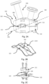
- Fig 2A shows a side view of an optical flow cell 100 according to an embodiment of the present invention.
- the housing comprises at least a first part 111, a second part 112 and a seal 113 located between the first and the second part 111, 112.
- the first part 111 and/or the second part 112 is/are configured to form the enclosed and elongated fluid channel 120 arranged along the first axis 123, the fluid channel 120 having an open side, and the corresponding first part 111 and/or the second part 112 is configured to close the open side of the fluid channel 120.
- the fluid channel 120 is configured with an arcuate channel wall opposite the open side.
- the first part 111 and/or the second part 112 comprises the inlet 130 and/or the outlet 140 further described in relation to Fig. 1B .
- the first part 111 and/or the second part 112 comprise/s the first light guide 161 and/or the second light guide 162 as further described in relation to Fig. 1C .
- An advantage of this embodiment is that complexity of forming the first and second light guide by cutting of the continuous light guide is reduced as the first and second part may be separated before performing cutting.
- the optical flow cell 100 may further comprise one or more fastening means 181, 182 configured to mount and/or secure and/or hold and/or secure the at least first part 111, second part 112 and the seal 113 to each other.
- fastening means 181, 182 configured to mount and/or secure and/or hold and/or secure the at least first part 111, second part 112 and the seal 113 to each other.
- the first part 111 and/or the second part 112 are single unitary pieces.
- An advantage of this embodiment is that probability of fluid leakage is reduced.
- a further advantage is that the first and second parts may be moulded for low cost.
- the single unitary pieces are affected, for example by thermal influences, more than more expensive materials used in some conventional optical flow cells, which may be made from titanium.
- the computer implemented method for measurement compensation/absorption value compensation further described in relation to Fig. 6 may be employed to counter these environmental effects and to account for possible manufacturing variances in the path length d.
- Fig 2B shows a perspective view of the seal 113 according to an embodiment of the present invention.
- the seal 113 may be made from an elastomer.
- the seal 113 may enclose edges of opposing surfaces of the first and second parts 111, 112.
- the seal 113 may comprise a saddle shaped surface 1133, where the length direction of the saddle shaped surface is perpendicular to the first axis 123.
- the advantage of the saddle shape is that the seal is centered in relation to the first and second part 111, 112.
- the first and second parts 111, 112 may further have a saddle shape and/or comprise a saddle shaped surface, where the length direction of the saddle shape and/or saddle shaped surface is perpendicular to the first axis 123.
- the saddle shape and/or saddle shaped surface of the first part 111 may further be configured to fit and/or closely match the saddle shape and/or saddle shaped surface of the second part 112 when the second part 112 is received by the first part.
- FIG. 1C shows an exploded view of an optical flow cell 100 according to an embodiment of the present invention.
- an optical flow cell 100 is provided that comprises a fluid flow path and/or a fluid channel 120 formed in a housing part and/or a second part 112 and extending along an axis and/or the first axis 123.
- the housing part 112 is further supporting opposed light guides 161, 162 on opposed walls 121, 122 of the fluid flow path and/or the fluid channel 120.
- the fluid flow path and/or the fluid channel 120 may be open at least on a side generally parallel with the axis and/or the first axis 123 for exposing said light guides.
- the fluid flow path and/or a fluid channel 120 may preferably have open ends, which allow access to removing a portion of a continuous light guide to form the opposed light guides 161, 162, e.g. to a cutting wheel or laser cutter during manufacture.
- the open side of the flow path and/or the fluid channel 120 may be closeable by a further housing part and/or a first part 111 to form the flow cell.
- the housing part and/or second part 112 is configured to form the fluid flow path and/or a fluid channel 120 extending along the first axis 123, the fluid channel 120 having an open side.
- the corresponding further housing part and/or first part 111 is configured to close the open side of the fluid flow path and/or a fluid channel 120.
- the fluid flow path and/or a fluid channel 120 is configured with an arcuate channel wall opposite the open side.
- Fig 3A shows detailed plan view of the seal 113 according to an embodiment of the present invention.
- the seal 113 may further comprise a first and second bore 1131, 1132 arranged on the second axis 170, wherein the first bore 1131 is arranged to allow the first light guide 161 to protrude through the first bore 1131 and the second light guide 162 is arranged to protrude through the second bore 1132 such that the exit surface of the first light guide 161 and the entrance surface of the second light guide 162 is separated by a path length and/or distance d.
- the first light guide 161 and the second light guide 162 may be arranged to protrude into the fluid channel 120.
- the advantage of this embodiment is that the seal prevents fluid from leaking out along the the first light guide 161 and/or the second light guide 162.
- Fig 3B shows detailed front view of the first bore 1131 comprised in the seal 113.
- Fig 4 shows detailed plan view of the fluid channel 120 according to an embodiment of the present invention.
- the fluid channel 120 comprises a first side wall 121 and a second side wall 122 of the opposite side walls previously described.
- the exit surface of the first light guide 161 is arranged adjacent to the first side wall 121 of the fluid channel 120, e.g. protruding from the first side wall of the fluid channel.
- the entrance surface of the second light guide 162 is arranged adjacent to the second opposing side wall 122 of the fluid channel 120.
- the exit surface and the entrance surface are separated by a path length and/or distance d.
- Fig. 4 also schematically illustrates the location of the first end 151 of the fluid channel where the inlet 130 connects to and the second end 152 of the fluid channel where the outlet 140 connects to.
- Fig. 5 shows a method of producing the optical flow cell according to an embodiment of the present invention. The method comprising:
- Preferably removing the portion is performed at and/or in the nominal environment such that the path length and/or distance d is equal to a nominal distance.
- the portion of the continuous light guide removed is comprised within the fluid channel 120.
- the optical flow cell housing 110 may be forming an enclosed and elongated fluid channel 120 arranged along a first axis 123 as further described in relation to figures 1A-C .
- the second axis 170 may be arranged perpendicular to the first axis 123.
- removing 720 the portion of the continuous light guide is performed by cutting the continuous light guide adjacent to the first side wall 121 of the fluid channel 120 and cutting the continuous light guide adjacent to the second opposing side wall 122 of the fluid channel 120.
- removing 720 the portion of the continuous light guide is performed in a motion along the first axis 123 and perpendicular to the second axis 170. In a further embodiment, removing 720 the portion of the continuous light guide is performed in a motion perpendicular to the first axis 123 and perpendicular to the second axis 170.
- the method further comprises assembling the first part 111, the second part 112 and the seal 113 located between the first and the second part 111, 112 to an optical flow cell housing 110.
- Fig. 6 shows a method 1000 performed by a measuring device 300 comprising the optical flow cell 100 according to any of the embodiments described herein. The method comprising:
- the compensation function compensates for variations of the path length and/or distance d dependent on the environment data.
- the environment data may be indicative of one or more of:
- the optical flow cell 100 is operating in 60° C of ambient temperature, resulting in a reduced path length and/or distance d.
- the above described method compensates the light absorption value for the reduced path length and/or distance d, thus resulting in an improved compensated light absorption value and improved measurement quality.
- the compensation function is obtained by measuring light absorption value at different temperatures. The measured light absorption values at different temperatures may then be used to and generate a compensation table and/or compensation function based on the obtained result.
- the optical flow cell 100 has been subjected to gamma irradiation and/or autoclaving, resulting in an altered thermal expansion coefficient and/or reduced path length and/or distance d.
- the above described method compensates the light absorption value for the altered thermal expansion coefficient and/or the reduced path length and/or distance d, thus resulting in an improved compensated light absorption value and improved measurement quality.
- the advantage of this embodiment is that the quality of measurements obtained using the optical flow cell 100 is improved.
- the optical flow cell 100 has been subjected to, such as ambient temperature, having been subjected to gamma irradiation and/or autoclaving.
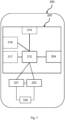
- Fig. 7 shows a measuring device 300 according to an embodiment of the present invention.
- the measuring device 300 may be configured for compensating a light absorption value measured in the optical flow cell 100 according to any of the embodiments described herein.
- the measuring device 300 may comprise a light generator 221, e.g. one or more Light Emitting Diodes (LED), Organic Light-Emitting
- the measuring device 300 may further comprise an absorption value generator 222 configured to receive reference light from the light generator 221 and received light from the optical flow cell 100 and generate a light absorption value.
- the measuring device 300 may further comprise a flow cell control unit 200, the unit comprising a processor 212 and a memory 215, said memory containing instructions executable by said processor, whereby said flow cell control unit 200 is operative and/ or configured to perform the method of any of the corresponding methods described herein.
- the absorption value generator 222 may comprise a first photodiode and/or light sensor configured to receive reference light from the light generator 221 and to generate a first signal indicative of the amplitude of the reference light.
- the absorption value generator 222 may further comprise a second photodiode and/or light sensor configured received light from the optical flow cell 100, e.g. from the entrance surface and to generate a second signal indicative of the amplitude of the received light from the optical flow cell 100.
- the absorption value generator 222 may further comprise a differentiator configured to receive the first and second signal and generate a light absorption value.
- the absorption value generator 222 may further be configured to send the light absorption value to the flow cell control unit 200.
- the measuring device 300 may be in the form of a server, an on-board computer, an digital information display, a stationary computing device, a laptop computer, a tablet computer, a handheld computer, a wrist-worn computer, a smart watch, a PDA, a Smartphone, a smart TV, a telephone, a media player, a game console, a vehicle mounted computer system or a navigation device.
- the processor 212 may be communicatively coupled to a transceiver 204 for wired or wireless communication. Further, the measuring device 300 may further comprise at least one optional antenna (not shown in the figure). The antenna may be coupled to the transceiver 204 and is configured to transmit and/or emit and/or receive a wireless signals in a wireless communication system. In one example, the processor 212 may be any of processing circuitry and/or a central processing unit and/or processor modules and/or multiple processors configured to cooperate with each-other. Further, the measuring device 300 may further comprise a memory 215. The memory 215 may contain instructions executable by the processor to perform the methods described herein. The processor 212 may be communicatively coupled to a selection of any of the transceiver 204 and the memory 215. The measuring device 300 may be configured to receive the absorption value/s directly from the absorption value generator 222 or via a wired and/or wireless communications network (not shown in the figure).
- the measuring device 300 may further comprise an input device 117, configured to receive input or indications from a user and send a user-input signal indicative of the user input or indications to the processing means 112.
- the measuring device 300 further comprises a display 118 configured to receive a display signal indicative of rendered objects, such as text or graphical user input objects, from the processing means 112 and to display the received signal as objects, such as text or graphical user input objects.
- the display 118 is integrated with the user input device 117 and is configured to receive a display signal indicative of rendered objects, such as text or graphical user input objects, from the processing means 112 and to display the received signal as objects, such as text or graphical user input objects, and/or configured to receive input or indications from a user and send a user-input signal indicative of the user input or indications to the processing means 112.
- the processor/processing means 112 is communicatively coupled to the memory 115 and/or the transceiver and/or the input device 117 and/or the display 118.
- the transceiver 104 communicates using any wired and/or wireless communication techniques known in the art, as further described below.
- the one or more memory 115 may comprise any of a selection of a hard RAM, disk drive, a floppy disk drive, a magnetic tape drive, an optical disk drive, a CD or DVD drive (R or RW), or other removable or fixed media drive.
- a computer program comprising computer-executable instructions for causing a measuring device 300 when the computer-executable instructions are executed on a processor/processing unit comprised in the measuring device 300, to perform any of the methods described herein.
- a computer program product comprising a memory and/or a computer-readable storage medium, the computer-readable storage medium having the computer program described above embodied therein.
- the memory and/or computer-readable storage medium referred to herein may comprise of essentially any memory, such as a ROM (Read-Only Memory), a PROM (Programmable Read-Only Memory), an EPROM (Erasable PROM), a Flash memory, an EEPROM (Electrically Erasable PROM), or a hard disk drive.
- the communications network communicate uses wired or wireless communication techniques that may include at least one of a Local Area Network (LAN), Metropolitan Area Network (MAN), Global System for Mobile Network (GSM), Enhanced Data GSM Environment (EDGE), Universal Mobile Telecommunications System, Long term evolution, High Speed Downlink Packet Access (HSDPA), Wideband Code Division Multiple Access (W-CDMA), Code Division Multiple Access (CDMA), Time Division Multiple Access (TDMA), Bluetooth ® , Zigbee ® , Wi-Fi, Voice over Internet Protocol (VoIP), LTE Advanced, IEEE802.16m, WirelessMAN-Advanced, Evolved High-Speed Packet Access (HSPA+), 3GPP Long Term Evolution (LTE), Mobile WiMAX (IEEE 802.16e), Ultra Mobile Broadband (UMB) (formerly Evolution-Data Optimized (EV-DO) Rev.
- LAN Local Area Network
- MAN Metropolitan Area Network
- GSM Global System for Mobile Network
- EDGE Enhanced Data GSM Environment
- Universal Mobile Telecommunications System Long term evolution
- Flash-OFDM Fast Low-latency Access with Seamless Handoff Orthogonal Frequency Division Multiplexing
- iBurst ® High Capacity Spatial Division Multiple Access
- MBWA Mobile Broadband Wireless Access
- IEEE 802.20 High Performance Radio Metropolitan Area Network
- HIPERMAN High Performance Radio Metropolitan Area Network
- BDMA Beam-Division Multiple Access
- Wi-MAX World Interoperability for Microwave Access
- ultrasonic communication etc., but is not limited thereto.
- the measuring device 300 may comprise the necessary communication capabilities in the form of e.g., functions, means, units, elements, etc., for performing the present solution.
- means, units, elements and functions are: processors, memory, buffers, control logic, encoders, decoders, rate matchers, de-rate matchers, mapping units, multipliers, decision units, selecting units, switches, interleavers, de-interleavers, modulators, demodulators, inputs, outputs, antennas, amplifiers, receiver units, transmitter units, DSPs, MSDs, TCM encoder, TCM decoder, power supply units, power feeders, communication interfaces, communication protocols, etc. which are suitably arranged together for performing the present solution.
- the processor of the present measuring device 300 may comprise a processor and/or processing circuitry and/or processing means, e.g., one or more instances of processing circuitry, processor modules and multiple processors configured to cooperate with each-other, Central Processing Unit (CPU), a processing unit, a processing circuit, a processor, an Application Specific Integrated Circuit (ASIC), a microprocessor, a Field-Programmable Gate Array (FPGA) or other processing logic that may interpret and execute instructions.
- CPU Central Processing Unit
- ASIC Application Specific Integrated Circuit
- FPGA Field-Programmable Gate Array
- the expression "processor” may thus represent a processing circuitry comprising a plurality of processing circuits, such as, e.g., any, some or all of the ones mentioned above.
- the processing means may further perform data processing functions for inputting, outputting, and processing of data comprising data buffering and device control functions, such as call processing control, user interface control, or the like.
Landscapes
- Physics & Mathematics (AREA)
- Health & Medical Sciences (AREA)
- Life Sciences & Earth Sciences (AREA)
- Chemical & Material Sciences (AREA)
- Analytical Chemistry (AREA)
- Biochemistry (AREA)
- General Health & Medical Sciences (AREA)
- General Physics & Mathematics (AREA)
- Immunology (AREA)
- Pathology (AREA)
- Optical Measuring Cells (AREA)
- Investigating Or Analysing Materials By Optical Means (AREA)
Claims (9)
- Verfahren (700) zur Herstellung einer optischen Durchflusszelle (100), wobei die Durchflusszelle umfasstein Gehäuse (110), das einen umschlossenen und länglichen Flüssigkeitskanal (120) bildet, der entlang einer ersten Achse (123) angeordnet ist;einen Einlass (130), der angeordnet ist, um einen ersten Außenoberflächenbereich des Gehäuses (110) mit einem ersten Ende (151) des Flüssigkeitskanals zu verbinden, und einen Auslass (140), der angeordnet ist, um einen zweiten Außenoberflächenbereich mit einem zweiten Ende (152) des Flüssigkeitskanals zu verbinden;einen ersten Lichtleiter (161) und einen zweiten Lichtleiter (162), die konzentrisch entlang einer zweiten Achse (170) und an gegenüberliegenden Seitenwänden des Flüssigkeitskanals angeordnet sind, wobei das Gehäuse mindestens einen ersten Teil (111), einen zweiten Teil (112) und eine Dichtung (113) umfasst, die sich zwischen dem ersten und dem zweiten Teil (111, 112) befindet, wobei der erste Teil (111) konfiguriert ist, um den umschlossenen und länglichen Flüssigkeitskanal (120) zu bilden, der entlang der ersten Achse (123) angeordnet ist;wobei der Flüssigkeitskanal (120) im ersten Teil (111) eine offene Seite aufweist und der entsprechende zweite Teil (112) konfiguriert ist, um die offene Seite des Flüssigkeitskanals (120) zu schließen, und wobei das Verfahren (700) gekennzeichnet ist durch:
Einsetzen (710) eines durchgehenden Lichtleiters in das Gehäuse (110) der optischen Durchflusszelle entlang einer zweiten Achse (170) und danach Entfernen (720) eines Abschnitts des durchgehenden Lichtleiters, um einen ersten Lichtleiter (161) zu bilden, der eine Austrittsoberfläche aufweist, an der Licht emittiert wird, und um einen zweiten Lichtleiter (162) zu bilden, der eine Eintrittsoberfläche aufweist, wobei der entfernte Abschnitt eine Länge aufweist, die einem Abstand (d) entspricht, sodass die Austrittsoberfläche und die Eintrittsoberfläche nach dem Entfernen des Abschnitts um den Abstand (d) getrennt sind. - Verfahren (700) nach Anspruch 1, wobei der erste Lichtleiter (161) die Austrittsoberfläche, an der Licht emittiert wird, neben der ersten Seitenwand (121) des Flüssigkeitskanals angeordnet umfasst, und wobei der zweite Lichtleiter (162) die Eintrittsoberfläche, an der das emittierte Licht empfangen wird, neben einer zweiten gegenüberliegenden Seitenwand (122) des Flüssigkeitskanals angeordnet umfasst.
- Verfahren (700) nach Anspruch 1 oder 2, wobei die Dichtung (113) Kanten gegenüberliegender Oberflächen des ersten und zweiten Teils (111, 112) umschließt und/oder die Dichtung eine erste und zweite Bohrung (1131, 1132) umfasst, die auf der zweiten Achse (170) angeordnet sind, wobei die erste Bohrung (1131) angeordnet ist, um zu ermöglichen, dass der erste Lichtleiter (161) durch die erste Bohrung (1131) hindurchragt, und der zweite Lichtleiter (162) angeordnet ist, um durch die zweite Bohrung (1132) hindurchzuragen.
- Verfahren (700) nach einem der vorstehenden Ansprüche, wobei der erste Lichtleiter (161) in einem ersten Verbinderteil (163) umschlossen ist und der zweite Lichtleiter (162) in einem zweiten Verbinderteil (164) umschlossen ist.
- Verfahren (700) nach Anspruch 4, weiter umfassend:ein erstes Befestigungselement, das angeordnet ist, um das erste Verbinderteil (163) an dem Gehäuse (100) zu befestigen oder zu sichern; undein zweites Befestigungselement, das angeordnet ist, um das zweite Verbinderteil (164) an dem Gehäuse (100) zu befestigen oder zu sichern.
- Verfahren (700) nach einem vorstehenden Anspruch, wobei das Entfernen (720) eines Abschnitts des durchgehenden Lichtleiters durch Schneiden des durchgehenden Lichtleiters neben einer ersten Seitenwand (121) des Flüssigkeitskanals (120), und Schneiden des durchgehenden Lichtleiters neben einer zweiten gegenüberliegenden Seitenwand (122) des Flüssigkeitskanals (120) durchgeführt wird.
- Verfahren (700) nach einem vorstehenden Anspruch, wobei das Entfernen (720) eines Abschnitts des durchgehenden Lichtleiters in einer Bewegung entlang der ersten Achse (123) und senkrecht zur zweiten Achse (170) durchgeführt wird.
- Verfahren (700) nach einem vorstehenden Anspruch, wobei das Entfernen (720) eines Abschnitts des durchgehenden Lichtleiters in einer Bewegung senkrecht zur ersten Achse (123) und senkrecht zur zweiten Achse (170) durchgeführt wird.
- Verfahren (700) nach einem vorstehenden Anspruch, wobei das Entfernen (720) eines Abschnitts des durchgehenden Lichtleiters unter Verwendung einer Diamantsäge oder durch Laserablation durchgeführt wird.
Priority Applications (1)
| Application Number | Priority Date | Filing Date | Title |
|---|---|---|---|
| EP24202921.3A EP4462104A3 (de) | 2016-11-30 | 2017-11-30 | Optische durchflusszelle |
Applications Claiming Priority (2)
| Application Number | Priority Date | Filing Date | Title |
|---|---|---|---|
| GBGB1620266.5A GB201620266D0 (en) | 2016-11-30 | 2016-11-30 | Optical flow cell |
| PCT/EP2017/080916 WO2018100032A1 (en) | 2016-11-30 | 2017-11-30 | Optical flow cell |
Related Child Applications (2)
| Application Number | Title | Priority Date | Filing Date |
|---|---|---|---|
| EP24202921.3A Division EP4462104A3 (de) | 2016-11-30 | 2017-11-30 | Optische durchflusszelle |
| EP24202921.3A Division-Into EP4462104A3 (de) | 2016-11-30 | 2017-11-30 | Optische durchflusszelle |
Publications (2)
| Publication Number | Publication Date |
|---|---|
| EP3548867A1 EP3548867A1 (de) | 2019-10-09 |
| EP3548867B1 true EP3548867B1 (de) | 2024-11-13 |
Family
ID=58073508
Family Applications (2)
| Application Number | Title | Priority Date | Filing Date |
|---|---|---|---|
| EP24202921.3A Pending EP4462104A3 (de) | 2016-11-30 | 2017-11-30 | Optische durchflusszelle |
| EP17807850.7A Active EP3548867B1 (de) | 2016-11-30 | 2017-11-30 | Herstellungsverfahren einer optischen durchflusszelle |
Family Applications Before (1)
| Application Number | Title | Priority Date | Filing Date |
|---|---|---|---|
| EP24202921.3A Pending EP4462104A3 (de) | 2016-11-30 | 2017-11-30 | Optische durchflusszelle |
Country Status (6)
| Country | Link |
|---|---|
| US (2) | US12066375B2 (de) |
| EP (2) | EP4462104A3 (de) |
| JP (2) | JP7066709B2 (de) |
| CN (1) | CN110234978A (de) |
| GB (1) | GB201620266D0 (de) |
| WO (1) | WO2018100032A1 (de) |
Families Citing this family (1)
| Publication number | Priority date | Publication date | Assignee | Title |
|---|---|---|---|---|
| GB201808748D0 (en) | 2018-05-29 | 2018-07-11 | Ge Healthcare Bio Sciences Ab | Optical flow cell |
Family Cites Families (37)
| Publication number | Priority date | Publication date | Assignee | Title |
|---|---|---|---|---|
| CH675759A5 (de) * | 1988-01-27 | 1990-10-31 | Karrer Weber & Cie Ag | |
| US5124130A (en) | 1990-05-22 | 1992-06-23 | Optex Biomedical, Inc. | Optical probe |
| US5403532A (en) * | 1990-11-14 | 1995-04-04 | Stecher; Friedhelm | Production process for a gasket and tool for performing the process |
| JP2763468B2 (ja) * | 1992-12-25 | 1998-06-11 | 株式会社日立製作所 | 光散乱を用いた液体内の粒子分類装置 |
| US5404217A (en) * | 1993-08-26 | 1995-04-04 | Janik; Gary R. | Laser liquid flow cell manifold system and method for assembly |
| JPH0915144A (ja) * | 1995-07-03 | 1997-01-17 | Toa Denpa Kogyo Kk | 吸光光度計およびこの吸光光度計の温度補償方法 |
| JPH1144821A (ja) | 1997-07-25 | 1999-02-16 | Yazaki Corp | 光ファイバアレイの製造方法 |
| US6438279B1 (en) * | 1999-01-07 | 2002-08-20 | Cornell Research Foundation, Inc. | Unitary microcapiliary and waveguide structure and method of fabrication |
| AU5942000A (en) | 1999-09-14 | 2001-03-15 | Whitaker Corporation, The | Process for cutting an optical fiber |
| MXPA02010596A (es) * | 2000-04-26 | 2003-03-10 | Glaxo Group Ltd | Metodo y aparato para el analisis espectroscopico in -situ. |
| US6369894B1 (en) * | 2000-05-01 | 2002-04-09 | Nalco Chemical Company | Modular fluorometer |
| US6862307B2 (en) | 2000-05-15 | 2005-03-01 | Lambda Physik Ag | Electrical excitation circuit for a pulsed gas laser |
| CN100537112C (zh) * | 2000-10-25 | 2009-09-09 | 伊鲁维斯有限公司 | 用于光纤或光波导的激光切割方法和装置 |
| JP2002221485A (ja) * | 2000-11-22 | 2002-08-09 | Minolta Co Ltd | マイクロチップ |
| JP4010418B2 (ja) * | 2004-02-04 | 2007-11-21 | 日本碍子株式会社 | 測定装置及びその製造方法 |
| US7184141B2 (en) * | 2004-03-23 | 2007-02-27 | Lockheed Martin Corporation | Optical flow cell for tribological systems |
| US20050257885A1 (en) | 2004-05-24 | 2005-11-24 | Nanostream, Inc. | Capillary multi-channel optical flow cell |
| JP2006125959A (ja) | 2004-10-28 | 2006-05-18 | Fujitsu Ltd | 被検体評価装置およびその製造方法 |
| JP4591963B2 (ja) | 2005-08-26 | 2010-12-01 | 日本電信電話株式会社 | 近接場光学センサ用ナノ流路およびその作製方法 |
| US7307717B2 (en) | 2005-09-16 | 2007-12-11 | Lockheed Martin Corporation | Optical flow cell capable of use in high temperature and high pressure environment |
| DE202005019457U1 (de) * | 2005-12-13 | 2006-02-09 | Agilent Technologies, Inc., Palo Alto | Fluidikvorrichtung für optische Anwendungen |
| US7651280B2 (en) * | 2005-12-14 | 2010-01-26 | Agilent Technologies, Inc. | Coupling for conduits sealed in a recess of a housing |
| GB0703250D0 (en) * | 2007-02-20 | 2007-03-28 | Ge Healthcare Bio Sciences Ab | Ultrasonic flow meter |
| US7673257B1 (en) | 2007-03-05 | 2010-03-02 | Calypto Design Systems, Inc. | System, method and computer program product for word-level operator-to-cell mapping |
| US20100060998A1 (en) | 2007-03-26 | 2010-03-11 | Kanji Sekihara | Microchip |
| US8154714B2 (en) * | 2008-11-06 | 2012-04-10 | Li-Cor, Inc. | Gas analyzer |
| JP5879127B2 (ja) * | 2008-11-24 | 2016-03-08 | ジーイー・ヘルスケア・バイオサイエンス・アクチボラグ | フローセル光学検出システム |
| EP2486399A2 (de) * | 2009-10-08 | 2012-08-15 | GE Healthcare UK Limited | Hochdruckflüssigchromatografiemodul mit mehreren strömen |
| WO2011093775A1 (en) | 2010-01-28 | 2011-08-04 | Ge Healthcare Bio-Sciences Ab | Optical flow cell detector |
| EP3460458B1 (de) | 2010-02-19 | 2021-08-11 | Pacific Biosciences of California, Inc. | Verfahren zur nukleinsäuresequenzierung |
| US20120119101A1 (en) | 2010-11-12 | 2012-05-17 | Endress + Hauser Conducta Gesellschaft Fur Mess-Und Regeltechnik Mbh + Co. Kg | Miniature UV sensor utilizing a disposable flow cell |
| US8638443B2 (en) | 2011-05-24 | 2014-01-28 | Honeywell International Inc. | Error compensation in a spectrometer |
| CN202794018U (zh) * | 2012-09-13 | 2013-03-13 | 山东省科学院海洋仪器仪表研究所 | 一种光纤接口的z型流通池 |
| GB201506095D0 (en) | 2015-04-10 | 2015-05-27 | Ge Healthcare Bio Sciences Ab | Optical flow cell for an optical measuring device |
| GB201506132D0 (en) | 2015-04-10 | 2015-05-27 | Ge Healthcare Bio Sciences Ab | Device for holding a light guide, and method for manufacturing such a device |
| CN204679411U (zh) | 2015-05-18 | 2015-09-30 | 深圳迈瑞生物医疗电子股份有限公司 | 光检测单元及使用该光检测单元的液相色谱分析装置 |
| US10197494B2 (en) * | 2016-06-23 | 2019-02-05 | Biocomp Instruments Inc. | Flow cell and system for simultaneous measurement of absorbance and emission in a sample |
-
2016
- 2016-11-30 GB GBGB1620266.5A patent/GB201620266D0/en not_active Ceased
-
2017
- 2017-11-30 WO PCT/EP2017/080916 patent/WO2018100032A1/en not_active Ceased
- 2017-11-30 EP EP24202921.3A patent/EP4462104A3/de active Pending
- 2017-11-30 US US16/464,759 patent/US12066375B2/en active Active
- 2017-11-30 JP JP2019528898A patent/JP7066709B2/ja active Active
- 2017-11-30 EP EP17807850.7A patent/EP3548867B1/de active Active
- 2017-11-30 CN CN201780084972.5A patent/CN110234978A/zh active Pending
-
2022
- 2022-04-26 JP JP2022072362A patent/JP7483786B2/ja active Active
-
2024
- 2024-07-17 US US18/775,959 patent/US20240369472A1/en active Pending
Also Published As
| Publication number | Publication date |
|---|---|
| JP2019536047A (ja) | 2019-12-12 |
| WO2018100032A1 (en) | 2018-06-07 |
| JP7483786B2 (ja) | 2024-05-15 |
| EP4462104A3 (de) | 2025-04-23 |
| CN110234978A (zh) | 2019-09-13 |
| US20190310182A1 (en) | 2019-10-10 |
| JP2022097578A (ja) | 2022-06-30 |
| JP7066709B2 (ja) | 2022-05-13 |
| US12066375B2 (en) | 2024-08-20 |
| GB201620266D0 (en) | 2017-01-11 |
| EP4462104A2 (de) | 2024-11-13 |
| EP3548867A1 (de) | 2019-10-09 |
| US20240369472A1 (en) | 2024-11-07 |
Similar Documents
| Publication | Publication Date | Title |
|---|---|---|
| US20240369472A1 (en) | Optical Flow Cell | |
| US11280722B2 (en) | Optical flow cell | |
| CN111106913B (zh) | 无线通信的方法和设备 | |
| US9110263B2 (en) | System and method for aligning a multi-core plastic optical fiber assembly | |
| US9515729B2 (en) | Omnidirectional free space optical communications receiver | |
| US11881925B2 (en) | System for operating multiple transceiver modules concurrently | |
| KR102327611B1 (ko) | 채널 상태 정보의 리포팅 방법 및 관련 장치 | |
| JP2015023582A (ja) | 無線ネットワーク装置によるネットワーク接続を制御する方法 | |
| EP2597807A1 (de) | Verfahren, system und ausrüstung zur überwachung von fehlercodes einer cpri-verbindung | |
| JP2022551564A5 (de) | ||
| US9838884B2 (en) | Radio wave status indicating apparatus, communication apparatus and computer-readable medium | |
| EP3187947B1 (de) | Steuerungssystem eines industriellen werkzeugs durch berechnung seiner position in bezug auf ein objekt, das sich auf einer montagestrasse bewegt | |
| US11474195B2 (en) | Optical interface | |
| US20040037515A1 (en) | Bendable optical signal transmitter port | |
| CN112788741B (zh) | 定位系统、定位方法、装置和移动终端 | |
| CN117406206A (zh) | 一种uwb设备的测距方法、电子设备及存储介质 | |
| CN112152704A (zh) | 通信控制方法、装置、存储介质及电子设备 | |
| US20230204495A1 (en) | Method for calibrating an apparatus for measuring the absorbance of light by a substance | |
| CN103576254A (zh) | 光模块 | |
| CN112994792A (zh) | 电子设备的通讯装置及电子设备 | |
| JP7328454B2 (ja) | 測定装置 | |
| JP2003232701A (ja) | 心線対照用光信号受光装置及びその使用方法 | |
| WO2026017244A1 (en) | Device and method for reporting measurements | |
| WO2025157610A1 (en) | Method for prediction of maintenance events in a chromatography apparatus | |
| JP5534464B2 (ja) | 光送受信器、及びその光信号最適化方法 |
Legal Events
| Date | Code | Title | Description |
|---|---|---|---|
| STAA | Information on the status of an ep patent application or granted ep patent |
Free format text: STATUS: UNKNOWN |
|
| STAA | Information on the status of an ep patent application or granted ep patent |
Free format text: STATUS: THE INTERNATIONAL PUBLICATION HAS BEEN MADE |
|
| PUAI | Public reference made under article 153(3) epc to a published international application that has entered the european phase |
Free format text: ORIGINAL CODE: 0009012 |
|
| STAA | Information on the status of an ep patent application or granted ep patent |
Free format text: STATUS: REQUEST FOR EXAMINATION WAS MADE |
|
| 17P | Request for examination filed |
Effective date: 20190607 |
|
| AK | Designated contracting states |
Kind code of ref document: A1 Designated state(s): AL AT BE BG CH CY CZ DE DK EE ES FI FR GB GR HR HU IE IS IT LI LT LU LV MC MK MT NL NO PL PT RO RS SE SI SK SM TR |
|
| AX | Request for extension of the european patent |
Extension state: BA ME |
|
| DAV | Request for validation of the european patent (deleted) | ||
| DAX | Request for extension of the european patent (deleted) | ||
| STAA | Information on the status of an ep patent application or granted ep patent |
Free format text: STATUS: EXAMINATION IS IN PROGRESS |
|
| 17Q | First examination report despatched |
Effective date: 20200630 |
|
| RAP1 | Party data changed (applicant data changed or rights of an application transferred) |
Owner name: CYTIVA SWEDEN AB |
|
| P01 | Opt-out of the competence of the unified patent court (upc) registered |
Effective date: 20230526 |
|
| GRAP | Despatch of communication of intention to grant a patent |
Free format text: ORIGINAL CODE: EPIDOSNIGR1 |
|
| STAA | Information on the status of an ep patent application or granted ep patent |
Free format text: STATUS: GRANT OF PATENT IS INTENDED |
|
| INTG | Intention to grant announced |
Effective date: 20240619 |
|
| GRAS | Grant fee paid |
Free format text: ORIGINAL CODE: EPIDOSNIGR3 |
|
| GRAA | (expected) grant |
Free format text: ORIGINAL CODE: 0009210 |
|
| STAA | Information on the status of an ep patent application or granted ep patent |
Free format text: STATUS: THE PATENT HAS BEEN GRANTED |
|
| AK | Designated contracting states |
Kind code of ref document: B1 Designated state(s): AL AT BE BG CH CY CZ DE DK EE ES FI FR GB GR HR HU IE IS IT LI LT LU LV MC MK MT NL NO PL PT RO RS SE SI SK SM TR |
|
| REG | Reference to a national code |
Ref country code: GB Ref legal event code: FG4D |
|
| REG | Reference to a national code |
Ref country code: CH Ref legal event code: EP |
|
| REG | Reference to a national code |
Ref country code: DE Ref legal event code: R096 Ref document number: 602017086124 Country of ref document: DE |
|
| REG | Reference to a national code |
Ref country code: IE Ref legal event code: FG4D |
|
| REG | Reference to a national code |
Ref country code: LT Ref legal event code: MG9D |
|
| REG | Reference to a national code |
Ref country code: NL Ref legal event code: MP Effective date: 20241113 |
|
| PG25 | Lapsed in a contracting state [announced via postgrant information from national office to epo] |
Ref country code: HR Free format text: LAPSE BECAUSE OF FAILURE TO SUBMIT A TRANSLATION OF THE DESCRIPTION OR TO PAY THE FEE WITHIN THE PRESCRIBED TIME-LIMIT Effective date: 20241113 Ref country code: PT Free format text: LAPSE BECAUSE OF FAILURE TO SUBMIT A TRANSLATION OF THE DESCRIPTION OR TO PAY THE FEE WITHIN THE PRESCRIBED TIME-LIMIT Effective date: 20250313 Ref country code: IS Free format text: LAPSE BECAUSE OF FAILURE TO SUBMIT A TRANSLATION OF THE DESCRIPTION OR TO PAY THE FEE WITHIN THE PRESCRIBED TIME-LIMIT Effective date: 20250313 |
|
| PG25 | Lapsed in a contracting state [announced via postgrant information from national office to epo] |
Ref country code: NL Free format text: LAPSE BECAUSE OF FAILURE TO SUBMIT A TRANSLATION OF THE DESCRIPTION OR TO PAY THE FEE WITHIN THE PRESCRIBED TIME-LIMIT Effective date: 20241113 Ref country code: FI Free format text: LAPSE BECAUSE OF FAILURE TO SUBMIT A TRANSLATION OF THE DESCRIPTION OR TO PAY THE FEE WITHIN THE PRESCRIBED TIME-LIMIT Effective date: 20241113 |
|
| REG | Reference to a national code |
Ref country code: AT Ref legal event code: MK05 Ref document number: 1742013 Country of ref document: AT Kind code of ref document: T Effective date: 20241113 |
|
| PG25 | Lapsed in a contracting state [announced via postgrant information from national office to epo] |
Ref country code: BG Free format text: LAPSE BECAUSE OF FAILURE TO SUBMIT A TRANSLATION OF THE DESCRIPTION OR TO PAY THE FEE WITHIN THE PRESCRIBED TIME-LIMIT Effective date: 20241113 |
|
| PG25 | Lapsed in a contracting state [announced via postgrant information from national office to epo] |
Ref country code: ES Free format text: LAPSE BECAUSE OF FAILURE TO SUBMIT A TRANSLATION OF THE DESCRIPTION OR TO PAY THE FEE WITHIN THE PRESCRIBED TIME-LIMIT Effective date: 20241113 |
|
| PG25 | Lapsed in a contracting state [announced via postgrant information from national office to epo] |
Ref country code: NO Free format text: LAPSE BECAUSE OF FAILURE TO SUBMIT A TRANSLATION OF THE DESCRIPTION OR TO PAY THE FEE WITHIN THE PRESCRIBED TIME-LIMIT Effective date: 20250213 |
|
| PG25 | Lapsed in a contracting state [announced via postgrant information from national office to epo] |
Ref country code: LV Free format text: LAPSE BECAUSE OF FAILURE TO SUBMIT A TRANSLATION OF THE DESCRIPTION OR TO PAY THE FEE WITHIN THE PRESCRIBED TIME-LIMIT Effective date: 20241113 Ref country code: AT Free format text: LAPSE BECAUSE OF FAILURE TO SUBMIT A TRANSLATION OF THE DESCRIPTION OR TO PAY THE FEE WITHIN THE PRESCRIBED TIME-LIMIT Effective date: 20241113 Ref country code: GR Free format text: LAPSE BECAUSE OF FAILURE TO SUBMIT A TRANSLATION OF THE DESCRIPTION OR TO PAY THE FEE WITHIN THE PRESCRIBED TIME-LIMIT Effective date: 20250214 |
|
| PG25 | Lapsed in a contracting state [announced via postgrant information from national office to epo] |
Ref country code: PL Free format text: LAPSE BECAUSE OF FAILURE TO SUBMIT A TRANSLATION OF THE DESCRIPTION OR TO PAY THE FEE WITHIN THE PRESCRIBED TIME-LIMIT Effective date: 20241113 |
|
| PG25 | Lapsed in a contracting state [announced via postgrant information from national office to epo] |
Ref country code: RS Free format text: LAPSE BECAUSE OF FAILURE TO SUBMIT A TRANSLATION OF THE DESCRIPTION OR TO PAY THE FEE WITHIN THE PRESCRIBED TIME-LIMIT Effective date: 20250213 |
|
| REG | Reference to a national code |
Ref country code: CH Ref legal event code: PL |
|
| PG25 | Lapsed in a contracting state [announced via postgrant information from national office to epo] |
Ref country code: SM Free format text: LAPSE BECAUSE OF FAILURE TO SUBMIT A TRANSLATION OF THE DESCRIPTION OR TO PAY THE FEE WITHIN THE PRESCRIBED TIME-LIMIT Effective date: 20241113 |
|
| PG25 | Lapsed in a contracting state [announced via postgrant information from national office to epo] |
Ref country code: DK Free format text: LAPSE BECAUSE OF FAILURE TO SUBMIT A TRANSLATION OF THE DESCRIPTION OR TO PAY THE FEE WITHIN THE PRESCRIBED TIME-LIMIT Effective date: 20241113 |
|
| PG25 | Lapsed in a contracting state [announced via postgrant information from national office to epo] |
Ref country code: LU Free format text: LAPSE BECAUSE OF NON-PAYMENT OF DUE FEES Effective date: 20241130 |
|
| REG | Reference to a national code |
Ref country code: CH Ref legal event code: PL |
|
| PG25 | Lapsed in a contracting state [announced via postgrant information from national office to epo] |
Ref country code: EE Free format text: LAPSE BECAUSE OF FAILURE TO SUBMIT A TRANSLATION OF THE DESCRIPTION OR TO PAY THE FEE WITHIN THE PRESCRIBED TIME-LIMIT Effective date: 20241113 |
|
| PG25 | Lapsed in a contracting state [announced via postgrant information from national office to epo] |
Ref country code: CH Free format text: LAPSE BECAUSE OF NON-PAYMENT OF DUE FEES Effective date: 20241130 |
|
| PG25 | Lapsed in a contracting state [announced via postgrant information from national office to epo] |
Ref country code: RO Free format text: LAPSE BECAUSE OF FAILURE TO SUBMIT A TRANSLATION OF THE DESCRIPTION OR TO PAY THE FEE WITHIN THE PRESCRIBED TIME-LIMIT Effective date: 20241113 |
|
| PG25 | Lapsed in a contracting state [announced via postgrant information from national office to epo] |
Ref country code: SK Free format text: LAPSE BECAUSE OF FAILURE TO SUBMIT A TRANSLATION OF THE DESCRIPTION OR TO PAY THE FEE WITHIN THE PRESCRIBED TIME-LIMIT Effective date: 20241113 |
|
| PG25 | Lapsed in a contracting state [announced via postgrant information from national office to epo] |
Ref country code: CZ Free format text: LAPSE BECAUSE OF FAILURE TO SUBMIT A TRANSLATION OF THE DESCRIPTION OR TO PAY THE FEE WITHIN THE PRESCRIBED TIME-LIMIT Effective date: 20241113 |
|
| PG25 | Lapsed in a contracting state [announced via postgrant information from national office to epo] |
Ref country code: IT Free format text: LAPSE BECAUSE OF FAILURE TO SUBMIT A TRANSLATION OF THE DESCRIPTION OR TO PAY THE FEE WITHIN THE PRESCRIBED TIME-LIMIT Effective date: 20241113 |
|
| REG | Reference to a national code |
Ref country code: DE Ref legal event code: R097 Ref document number: 602017086124 Country of ref document: DE |
|
| REG | Reference to a national code |
Ref country code: BE Ref legal event code: MM Effective date: 20241130 |
|
| PG25 | Lapsed in a contracting state [announced via postgrant information from national office to epo] |
Ref country code: SE Free format text: LAPSE BECAUSE OF FAILURE TO SUBMIT A TRANSLATION OF THE DESCRIPTION OR TO PAY THE FEE WITHIN THE PRESCRIBED TIME-LIMIT Effective date: 20241113 |
|
| PG25 | Lapsed in a contracting state [announced via postgrant information from national office to epo] |
Ref country code: MC Free format text: LAPSE BECAUSE OF FAILURE TO SUBMIT A TRANSLATION OF THE DESCRIPTION OR TO PAY THE FEE WITHIN THE PRESCRIBED TIME-LIMIT Effective date: 20241113 |
|
| PLBE | No opposition filed within time limit |
Free format text: ORIGINAL CODE: 0009261 |
|
| STAA | Information on the status of an ep patent application or granted ep patent |
Free format text: STATUS: NO OPPOSITION FILED WITHIN TIME LIMIT |
|
| PG25 | Lapsed in a contracting state [announced via postgrant information from national office to epo] |
Ref country code: BE Free format text: LAPSE BECAUSE OF NON-PAYMENT OF DUE FEES Effective date: 20241130 |
|
| 26N | No opposition filed |
Effective date: 20250814 |
|
| PG25 | Lapsed in a contracting state [announced via postgrant information from national office to epo] |
Ref country code: IE Free format text: LAPSE BECAUSE OF NON-PAYMENT OF DUE FEES Effective date: 20241130 |
|
| PGFP | Annual fee paid to national office [announced via postgrant information from national office to epo] |
Ref country code: DE Payment date: 20251126 Year of fee payment: 9 |
|
| PGFP | Annual fee paid to national office [announced via postgrant information from national office to epo] |
Ref country code: GB Payment date: 20251125 Year of fee payment: 9 |
|
| PGFP | Annual fee paid to national office [announced via postgrant information from national office to epo] |
Ref country code: FR Payment date: 20251125 Year of fee payment: 9 |
|
| PG25 | Lapsed in a contracting state [announced via postgrant information from national office to epo] |
Ref country code: CY Free format text: LAPSE BECAUSE OF FAILURE TO SUBMIT A TRANSLATION OF THE DESCRIPTION OR TO PAY THE FEE WITHIN THE PRESCRIBED TIME-LIMIT; INVALID AB INITIO Effective date: 20171130 |