EP3548670B1 - Bollwerkstruktur und verfahren - Google Patents
Bollwerkstruktur und verfahren Download PDFInfo
- Publication number
- EP3548670B1 EP3548670B1 EP17857686.4A EP17857686A EP3548670B1 EP 3548670 B1 EP3548670 B1 EP 3548670B1 EP 17857686 A EP17857686 A EP 17857686A EP 3548670 B1 EP3548670 B1 EP 3548670B1
- Authority
- EP
- European Patent Office
- Prior art keywords
- panels
- retaining
- panel
- substantially vertical
- bunds
- Prior art date
- Legal status (The legal status is an assumption and is not a legal conclusion. Google has not performed a legal analysis and makes no representation as to the accuracy of the status listed.)
- Active
Links
Images





Classifications
-
- E—FIXED CONSTRUCTIONS
- E02—HYDRAULIC ENGINEERING; FOUNDATIONS; SOIL SHIFTING
- E02D—FOUNDATIONS; EXCAVATIONS; EMBANKMENTS; UNDERGROUND OR UNDERWATER STRUCTURES
- E02D17/00—Excavations; Bordering of excavations; Making embankments
- E02D17/18—Making embankments, e.g. dikes, dams
-
- B—PERFORMING OPERATIONS; TRANSPORTING
- B09—DISPOSAL OF SOLID WASTE; RECLAMATION OF CONTAMINATED SOIL
- B09B—DISPOSAL OF SOLID WASTE NOT OTHERWISE PROVIDED FOR
- B09B1/00—Dumping solid waste
-
- B—PERFORMING OPERATIONS; TRANSPORTING
- B65—CONVEYING; PACKING; STORING; HANDLING THIN OR FILAMENTARY MATERIAL
- B65G—TRANSPORT OR STORAGE DEVICES, e.g. CONVEYORS FOR LOADING OR TIPPING, SHOP CONVEYOR SYSTEMS OR PNEUMATIC TUBE CONVEYORS
- B65G5/00—Storing fluids in natural or artificial cavities or chambers in the earth
-
- E—FIXED CONSTRUCTIONS
- E02—HYDRAULIC ENGINEERING; FOUNDATIONS; SOIL SHIFTING
- E02D—FOUNDATIONS; EXCAVATIONS; EMBANKMENTS; UNDERGROUND OR UNDERWATER STRUCTURES
- E02D29/00—Independent underground or underwater structures; Retaining walls
- E02D29/02—Retaining or protecting walls
-
- E—FIXED CONSTRUCTIONS
- E02—HYDRAULIC ENGINEERING; FOUNDATIONS; SOIL SHIFTING
- E02D—FOUNDATIONS; EXCAVATIONS; EMBANKMENTS; UNDERGROUND OR UNDERWATER STRUCTURES
- E02D29/00—Independent underground or underwater structures; Retaining walls
- E02D29/02—Retaining or protecting walls
- E02D29/0258—Retaining or protecting walls characterised by constructional features
- E02D29/0266—Retaining or protecting walls characterised by constructional features made up of preformed elements
-
- E—FIXED CONSTRUCTIONS
- E02—HYDRAULIC ENGINEERING; FOUNDATIONS; SOIL SHIFTING
- E02D—FOUNDATIONS; EXCAVATIONS; EMBANKMENTS; UNDERGROUND OR UNDERWATER STRUCTURES
- E02D29/00—Independent underground or underwater structures; Retaining walls
- E02D29/02—Retaining or protecting walls
- E02D29/0225—Retaining or protecting walls comprising retention means in the backfill
-
- E—FIXED CONSTRUCTIONS
- E02—HYDRAULIC ENGINEERING; FOUNDATIONS; SOIL SHIFTING
- E02D—FOUNDATIONS; EXCAVATIONS; EMBANKMENTS; UNDERGROUND OR UNDERWATER STRUCTURES
- E02D29/00—Independent underground or underwater structures; Retaining walls
- E02D29/02—Retaining or protecting walls
- E02D29/0225—Retaining or protecting walls comprising retention means in the backfill
- E02D29/0233—Retaining or protecting walls comprising retention means in the backfill the retention means being anchors
-
- Y—GENERAL TAGGING OF NEW TECHNOLOGICAL DEVELOPMENTS; GENERAL TAGGING OF CROSS-SECTIONAL TECHNOLOGIES SPANNING OVER SEVERAL SECTIONS OF THE IPC; TECHNICAL SUBJECTS COVERED BY FORMER USPC CROSS-REFERENCE ART COLLECTIONS [XRACs] AND DIGESTS
- Y02—TECHNOLOGIES OR APPLICATIONS FOR MITIGATION OR ADAPTATION AGAINST CLIMATE CHANGE
- Y02W—CLIMATE CHANGE MITIGATION TECHNOLOGIES RELATED TO WASTEWATER TREATMENT OR WASTE MANAGEMENT
- Y02W30/00—Technologies for solid waste management
- Y02W30/30—Landfill technologies aiming to mitigate methane emissions
Definitions
- the present invention relates to retaining structures and, more particularly although not exclusively, to structures for retaining waste material.
- a major disadvantage of this type of retaining structure is the large footprint demanded by the bund formations.
- a further associated disadvantage is the large area of the sloping bund walls which must be covered with the expensive impervious liner material which can be easily damaged.
- GB 2 460 342 A discloses a bund system according to the preamble of claim 1.
- a bund system as defined in claim 1 for the retention of solid or liquid or pourable waste material.
- the retaining structures comprise a double row of spaced apart, substantially vertical panels; the substantially vertical panels maintained in substantially vertical and spaced apart position on the ground surface by retaining elements projecting from each row of the double row of panels towards an opposite row; the retaining structures maintained in the selected position by the mass of compacted material back-filled between the spaced apart, substantially vertical panels.
- At least a proportion of the retaining elements interconnect selected opposing panels of the double row of spaced apart, substantially vertical panels.
- each of the retaining elements extends from the spaced apart, substantially vertical panels across a portion of the spacing between the double row of panels.
- the retaining elements are rods affixed at a first proximate ends at an inward facing surface of the spaced apart, substantially vertical panels; a second distal ends of each of the rods provided with a projecting structure extending beyond a periphery of the distal end of the rod.
- the projecting structure is adapted for a bolted connection to anchor points provided at inward facing surfaces of the spaced apart, substantially vertical panels.
- adjacent vertical edges of adjoining inward facing panels of the spaced apart, substantially vertical panels are respectively provided with one of two forms of flexible sealing elements; a first form comprising a strip of flexible polymer material overlaying a surface section of a first panel proximate an adjacent vertical edge of the first panel; a second form comprising a strip of flexible polymer material overlaying a surface portion of a second panel proximate an adjacent vertical edge of the second panel and including an overlap portion extending past the adjacent vertical edge of the second panel; the overlap portion of the second panel heat welded to the strip of flexible polymer overlaying the surface portion of the first panel.
- the retaining structures comprise a substantially horizontal base element and a substantially vertical element extending from the substantially horizontal base element.
- the substantially vertical element extends from proximate an edge of the substantially horizontal element to form substantially "L"-shaped retaining structures including a horizontal base panel and a vertical panel.
- waste material is retained between opposing lines of the substantially "L"-shaped retaining structures; the opposing lines arranged with the horizontal panels facing inwards one to another.
- the retaining structures comprise inverted "T" - shaped retaining structures; the "T"-shaped retaining structures each comprising a substantially horizontal base panel and a substantially vertical panel extending from the base panel intermediate outer edges of the substantially horizontal base panel.
- adjacent vertical and horizontal edges of adjoining retaining structures are respectively provided with one of two forms of flexible sealing elements; a first form comprising a strip of flexible polymer material overlaying surface sections of a first retaining structure proximate adjacent vertical and horizontal edges of the first retaining structure; a second form comprising a strip of flexible polymer material overlaying surface portions of a second retaining structure proximate adjacent vertical and horizontal edges of the second retaining structure and including an overlap portion extending past the adjacent vertical edge of the second retaining structure; the overlap portion of the second retaining structure heat welded to the strip of flexible polymer overlaying the surface portion of the first retaining structure.
- a waste retention area is surrounded by the bunds; an impervious liner extending across a ground surface of the waste retention area and extending up inward facing surfaces of the substantially vertical structural elements.
- a waste retention area is surrounded by the bunds; an impervious liner extending across a ground surface of the waste retention area; outer edges of the impervious liner welded to seal elements provided along lower edges of the substantially vertical structural elements.
- the retaining structures are formed of precast concrete.
- each panel is provided with at least one retaining element; the at least one retaining element projecting from an inner surface of the panel and extending at least across a part of the predetermined separation between the double rows of panels.
- the retaining element is provided at a distal end with a projection adapted for a bolted connection of the retaining element to the inner surface of an opposing panel of a double row of panels.
- the method includes the step of securing the distal ends of the retaining structures to the opposing panels.
- the method includes the further step of filling space between the double rows of panels with a back fill material.
- a method of forming a waste retention area by enclosing the waste retention area by bunds comprising at least one substantially vertical retaining structure relative a base extending over a portion of a ground surface; the method including the steps of;
- the retaining structures comprise substantially "L"-shaped retaining structures.
- the retaining structures comprise inverted "T"-shaped retaining structures.
- a conventional land fill cell or containment dam 1 is surrounded by bunds 2 formed by earth embankments with side slopes typically at 1V:3H. These embankments demand a very large footprint relative the actual volume of waste material which can be accommodated.
- bunds 2 formed by earth embankments with side slopes typically at 1V:3H.
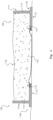
- a bund system 10 is formed of bunds 12 comprising a double row of spaced apart, substantially vertical panels 14 forming retaining structures.
- the panels 14 are maintained in a substantially vertical and spaced apart position by one or more retaining elements 16 which project from each panel 14 of the row of the double row of panels towards the opposite row.
- the retaining elements 16 are rods which interconnect the panels of one row with panels of the opposite row.
- a first proximate end 18 of a retaining element is affixed at an inner surface 20 of the spaced apart, substantially vertical panels.
- a second distal end 22 of each of the rods is provided with a projecting structure 24 extending beyond a periphery of the end of the rod.
- the projecting structure 24 is adapted for a bolted connection to anchor points (not shown) provided at inner surfaces of the panels 14.
- the retaining elements 16 extend from the inward facing surface of panels 14 across only a portion of the spacing between the double rows of panels.
- the projecting structures 24 are adapted to form soil anchors. After erection of the double row of panels at a predetermined separation, the space between the rows is filled with a back fill material 26, effectively locking the panels into their substantially vertical position by the soil anchor projecting structures 24 engaging with the back fill material 26.
- the mass of back-fill compacted material introduced between the opposing panels forming the bunds acts to retain the bunds in a selected position on a ground surface.
- At least a second tier of bunds may be erected on the first to double the capacity of waste material which can be retained.
- a bund system is again comprised of rows of spaced apart, substantially vertical panels as described for the first embodiment above.
- the panels are retained in their substantially vertical position by retaining elements, either interconnecting opposing panels or locked into back fill introduced into the space between the panels.
- the bunds may be used to raise the retaining height of an existing, earth construction bund 40.
- the original liner may be replaced by one which extends up the outer surfaces of the inward facing panels of the inward facing row of panels 14 forming the added bund.
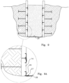
- the outer edges 27 of the liner 28 may be welded to a seal element 29 at the lower edge of the panels as described in WO 2014/205495 by the applicant, incorporated herein by reference, and as shown in Figure 9 and 9A .
- the panels 14 are preferably of precast concrete.
- an impervious liner 28 covers the ground surface 30 enclosed by the bunds 12 and may extend up the inward facing surfaces 32 of the inward facing row of panels 14.
- the precast concrete panels 14 may be inherently impervious.
- the vertical joints between adjacent panels 14 may be sealed with flexible seal members in the manner described in WO 2014/205495 and as best seen in Figure 10 .
- each of opposite ends of concrete panels is respectively provided with one of two flexible seal members, the overlap portion of one of them at a first end of one panel welded to a surface component at the second and adjoining end of an adjacent panel.
- footings 34 are prepared and the two rows of panels 14 of lengths of bund system 10 are erected at a predetermined spacing and temporarily held in a substantially vertical position by suitable supports. At least one retaining element 16 is then affixed to the inward facing surface of each panel. Where the retaining elements are provided with projecting structures adapted for bolted connection to anchor points on opposing panels, the rows of panels will have been arranged with a separation equal to the length of the retaining elements and these projecting structures and then bolted into position. The supports may then be removed, the bund now self-supporting, the mass of the waste material acting to retain the bund formed in the selected position.
- the rows of panels are arranged at a separation at which the retaining elements extend only a part way across the width of the separation. Suitable compacted back fill is then introduced into the space between the rows, the soil anchors locking the panels forming the bund into their substantially vertical position.
- the bund system of the invention provides for a very significant increase in the volume of waste material which can be accommodated compared with that of a conventional, earth construction bund of similar dimensions.
- adjacent vertical edges of adjoining inward facing panels 14 of the spaced apart, substantially vertical panels are respectively provided with sealing elements 15 of the type described in WO 2014/205495 and as shown in Figure 10 to form a continuous impervious barrier.
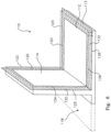
- bunds 100 are formed as lines of precast, substantially "L" or “T”-shaped retaining structures 110, each including a horizontal base panel 112 and a vertical panel 114 extending upwards from an edge of the horizontal base panel.
- base panel 112 may extend beyond the vertical panel 114, as shown in Figures 6 and 7 , with the extension 118 even tending towards the retaining structure taking the form of an inverted "T"-shaped retaining structure.
- Waste or liquid material 116 is retained between opposing lines of the "L"-shaped retaining structures 110 with the opposing lines arranged with the horizontal panels 112 facing inwards one towards another.
- the bunds 100 are retained in this instance by a combination of the mass of the waste material, either solid or liquid acting on the horizontal base panels 112, and the resistance to tipping provided by the extension 118.
- the substantially “L” or “T”-shaped retaining structures 110 are also provided with sealing elements to make a line of the retaining structures form an impervious barrier.
- These sealing elements again conform to the two forms of sealing element disclosed in WO 2014/205495 .
- These sealing elements include sealing elements 113 arranged along the inward or outward facing edges of the horizontal base panels 112, and provided for an impervious liner 115 extending between the retaining structures 110 and heat welded to the sealing elements 113.
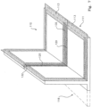
- adjacent vertical and horizontal edges of adjoining substantially "L"-shaped retaining structures 110 are respectively provided with one of two forms of flexible sealing elements.
- a first form 120 comprising a strip of flexible polymer material overlays vertical and horizontal surface sections of an "L"-shaped retaining structure 110 proximate adjacent vertical and horizontal edges 122 and 124.
- the second form 126 comprising another strip of flexible polymer material overlays vertical and horizontal surface portions of the "L"-shaped retaining structure proximate opposite vertical and horizontal edges 128 and 130 and includes an overlap portion 132 extending past the adjacent vertical and horizontal edges 134 and 136 .
- the overlap portion 132 of a first retaining structure 110 of two adjacent retaining structures 110 and 111 partially overlaps the strip of polymer sealing element 120 allowing its edge to be heat welded to the sealing element 120.
- bunds 200 for enclosing a land fill cell 210 are formed from precast concrete, as inverted "T"-shaped bund structures 212, in which the substantially vertical panel 220 extends upward from the midpoint of the substantially horizontal base panel 222.
- the ground surface 214 of the cell or dam 200 is provided with an impervious liner 216 which, extends over the ground surface between the structures and is thermally welded to sealing elements provided along the inward facing edges as described above. Vertical joints between adjacent bund structures 212 are sealed by the sealing system described above.
- the height of the substantially vertical panel 220 of the "T"- shaped bund structures 212, and the width of the substantially horizontal base panel 222 are selected so as to be able to retain the mass of waste material 224 between the surrounding bund structures.
- Stability of the bund structure may therefore be assured by selecting an optimum configuration of the base panel relative the vertical panel either as substantially “L"-shaped or as an inverted "T"-shape.
- a solid or liquid waste retention area may be formed by arranging on a ground surface retaining elements according to any of the above embodiments to form an enclosed area.
- a ground surface retaining elements according to any of the above embodiments.
- these are positioned with horizontal base panels of the retaining structures facing inwards to the enclosed area.
- the retaining structures may additionally function as internal dividers in such a waste cell.
- the retaining structures of the invention may be used for example for a tank farm fuel perimeter.
- the bund structures rely on a wide base element with at least one vertical retaining structure. Also common to each of these embodiments is that the structures are retained in a position on a ground surface by the interaction of the structure with a mass, be that mass a back fill as in the first and second preferred embodiments, or is comprised of a portion of the retained waste material, as in the third and fourth embodiments.
- bund structures of the present invention to retain waste material with elements having a far smaller footprint than that of bunds of the prior art provides for a very considerable reduction in the ecological impact of land fill cells, both through the reduced space required and the greater efficiency in the sealing against ground water pollution.
Landscapes
- Engineering & Computer Science (AREA)
- Mining & Mineral Resources (AREA)
- Environmental & Geological Engineering (AREA)
- Life Sciences & Earth Sciences (AREA)
- General Life Sciences & Earth Sciences (AREA)
- Paleontology (AREA)
- Civil Engineering (AREA)
- General Engineering & Computer Science (AREA)
- Structural Engineering (AREA)
- Geology (AREA)
- Processing Of Solid Wastes (AREA)
Claims (14)
- - Umwallungssystem (10) für die Rückhaltung von festem oder flüssigem oder schüttfähigem Abfallmaterial; Umwallungen (12) des Umwallungssystem (10) umfassend Rückhaltestrukturen umfassen; wobei die Rückhaltestrukturen mindestens ein vertikales Strukturelement beinhalten, umfassend Doppelreihen von beabstandeten, im Wesentlichen vertikalen Platten (14) in Bezug auf eine Basis; wobei die Basis einen Abschnitt einer Bodenoberfläche (30) bedeckt; wobei die Umwallungen (12) durch die Wechselwirkung von Rückhalteelementen (16) mit einer Masse von verdichtetem Aufschüttungsmaterial (26) in dem Zwischenraum zwischen der Doppelreihe von Platten (14) in einer ausgewählten Position auf der Bodenoberfläche (30) gehalten werden; dadurch gekennzeichnet, dass sich die Rückhalteelemente (16) von nach innen weisenden Oberflächen der im Wesentlichen vertikalen Platten (14) über nur einen Teil des Zwischenraums zwischen der Doppelreihe von Platten (14) erstrecken; wobei die Rückhalteelemente (16) an einem distalen Ende (22) mit Vorsprüngen (24) versehen sind, die als Bodenanker wirken, um die im Wesentlichen vertikalen Platten (14) in der im Wesentlichen vertikalen Position zu arretieren.
- - Umwallungssystem (10) nach Anspruch 1, wobei zumindest ein Teil der Rückhalteelemente (16) ausgewählte gegenüberliegende Platten (14) der Doppelreihe von beabstandeten, im Wesentlichen vertikalen Platten (14) miteinander verbindet.
- - Umwallungssystem (10) nach Anspruch 1, wobei sich jedes der Rückhalteelemente (16) über einen Abschnitt des Zwischenraums zwischen der Doppelreihe von Platten (14) von den beabstandeten, im Wesentlichen vertikalen Platten (14) erstreckt.
- - Umwallungssystem (10) nach Anspruch 2 oder 3, wobei die Rückhalteelemente (16) Stangen sind, die an einem ersten nahen Ende (18) an einer nach innen weisenden Fläche der beabstandeten, im Wesentlichen vertikalen Platten (14) befestigt sind; wobei ein zweites distales Ende (22) von jeder der Stangen mit einer hervorstehenden Struktur (24) versehen ist, die sich über einen Umfang des distalen Endes (22) der Stange hinaus erstreckt.
- - Umwallungssystem nach einem der Ansprüche 2 bis 4, wobei benachbarte vertikale Ränder aneinandergrenzender, nach innen gerichteter Platten der voneinander beabstandeten, im Wesentlichen vertikalen Platten jeweils mit einer von zwei Formen flexibler Dichtungselemente versehen sind; eine erste Form, umfassend einen Streifen aus flexiblem Polymermaterial, der einen Oberflächenabschnitt einer ersten Platte in der Nähe eines benachbarten vertikalen Rands der ersten Platte überlagert; eine zweite Form, die einen Streifen aus flexiblem Polymermaterial umfasst, der einen Oberflächenabschnitt einer zweiten Platte in der Nähe eines benachbarten vertikalen Rands der zweiten Platte überlagert und einen Überlappungsabschnitt beinhaltet, der sich über den benachbarten vertikalen Rand der zweiten Platte erstreckt; wobei der Überlappungsabschnitt der zweiten Platte mit dem Streifen aus flexiblem Polymer, der den Oberflächenabschnitt der ersten Platte überlagert, heißverschweißt ist.
- - Umwallungssystem nach Anspruch 1, wobei die Rückhaltestrukturen ein im Wesentlichen horizontales Basiselement und ein im Wesentlichen vertikales Element umfassen, das sich von dem im Wesentlichen horizontalen Basiselement erstreckt.
- - Umwallungssystem nach Anspruch 6, wobei benachbarte vertikale und horizontale Ränder angrenzender Rückhaltestrukturen jeweils mit einer von zwei Formen flexibler Dichtungselemente versehen sind; eine erste Form, die einen Streifen aus flexiblem Polymermaterial umfasst, der Oberflächenabschnitte einer ersten Rückhaltestruktur in der Nähe benachbarter vertikaler und horizontaler Ränder der ersten Rückhaltestruktur überlagert; eine zweite Form, die einen Streifen aus flexiblem Polymermaterial umfasst, der Oberflächenabschnitte einer zweiten Rückhaltestruktur in der Nähe benachbarter vertikaler und horizontaler Kanten der zweiten Rückhaltestruktur überlagert und einen Überlappungsabschnitt beinhaltet, der sich über den benachbarten vertikalen Kante der zweiten Rückhaltestruktur erstreckt; wobei der Überlappungsabschnitt der zweiten Rückhaltestruktur mit dem Streifen aus flexiblem Polymer, der den Oberflächenabschnitt der ersten Rückhaltestruktur überlagert, heißverschweißt ist.
- - Umwallungssystem (10) nach einem der vorherigen Ansprüche, wobei ein Abfallrückhaltebereich von den Umwallungen (12) umgeben ist; sich eine undurchlässige Auskleidung (28) über eine Bodenoberfläche (30) des Abfallrückhaltebereichs erstreckt und sich bis zu nach innen gerichteten Oberflächen der im Wesentlichen vertikalen Strukturelemente erstreckt.
- - Umwallungssystem nach einem der vorherigen Ansprüche, wobei ein Abfallrückhaltebereich von den Bündeln umgeben ist; sich eine undurchlässige Auskleidung (28) über eine Bodenoberfläche (30) des Abfallrückhaltebereichs erstreckt; äußere Ränder (27) der undurchlässigen Auskleidung (28) mit Dichtungselementen (29) verschweißt sind, die entlang der unteren Ränder der im Wesentlichen vertikalen Strukturelemente bereitgestellt sind.
- - Verfahren zum Bilden eines Abfallrückhaltebereichs durch Umschließen des Abfallrückhaltebereichs durch Umwallungen (12); die Umwallungen (12) umfassend mindestens ein im Wesentlichen vertikales Strukturelement (14) in Bezug auf eine Basis, die sich über einen Abschnitt einer Bodenoberfläche (30) erstreckt; wobei das Verfahren die folgenden Schritte beinhaltet:- Vorbereiten von Fundamenten (34),- Platzieren von Umwallungen (12), die aus Platten (14) gebildet sind, auf den Fundamenten (34) in Doppelreihen, die in einem vorbestimmten Abstand beabstandet sind, um den Abfallrückhaltebereich zu umschließen,- Installieren einer undurchlässigen Auskleidung (28), um eine Bodenfläche (30) des Abfallrückhaltebereichs zu bedecken; wobei sich die Auskleidung (28) mindestens bis zu einer Basis von nach innen weisenden Oberflächen von nach innen weisenden Platten (14) der Doppelreihen von Platten erstreckt, undwobei die Umwallungen (12) durch Wechselwirkung mit einer Masse von verdichtetem Material (26) in dem Raum zwischen den Doppelreihen von im Wesentlichen vertikalen Platten (14) in einer ausgewählten Position zurückgehalten werden, und wobei jede Platte (14) mit mindestens einem Rückhalteelement (16) versehen ist, das von einer Innenfläche der Platte (16) hervorsteht und sich nur über einen Abschnitt des vorbestimmten Abstands erstreckt; wobei jedes Rückhalteelement (16) an einem distalen Ende (22) mit einem Vorsprung (24) versehen ist, um einen Bodenanker zu bilden.
- - Verfahren nach Anspruch 10, wobei jede Platte (14) mit mindestens einem Rückhalteelement (16) versehen ist, wobei das mindestens eine Rückhalteelement (16) von einer Innenfläche der Platte (14) hervorsteht und sich zumindest über einen Teil des vorbestimmten Abstands zwischen den Doppelreihen von Platten (14) erstreckt.
- - Verfahren nach Anspruch 11, wobei das Rückhalteelement (16) an einem distalen Ende (22) mit einem Vorsprung (24) versehen ist, der für eine Schraubverbindung des Rückhalteelements (16) mit der Innenfläche einer gegenüberliegenden Platte (14) einer Doppelreihe von Platten (14) geeignet ist.
- - Verfahren nach Anspruch 12, wobei das Verfahren den Schritt eines Befestigens der distalen Enden (18, 22) der Rückhaltestrukturen an den gegenüberliegenden Platten (14) beinhaltet.
- - Verfahren nach einem der Ansprüche 10 bis 13, wobei das Verfahren den weiteren Schritt eines Füllens des Raums zwischen den Doppelreihen der Platten (14) mit einem Hinterfüllmaterial (26) beinhaltet.
Applications Claiming Priority (2)
| Application Number | Priority Date | Filing Date | Title |
|---|---|---|---|
| AU2016238840A AU2016238840B2 (en) | 2016-10-04 | 2016-10-04 | Bulwark Structure and Method |
| PCT/AU2017/000207 WO2018064707A1 (en) | 2016-10-04 | 2017-10-04 | Bulwark structure and method |
Publications (4)
| Publication Number | Publication Date |
|---|---|
| EP3548670A1 EP3548670A1 (de) | 2019-10-09 |
| EP3548670A4 EP3548670A4 (de) | 2020-11-25 |
| EP3548670B1 true EP3548670B1 (de) | 2023-12-06 |
| EP3548670C0 EP3548670C0 (de) | 2023-12-06 |
Family
ID=61830750
Family Applications (1)
| Application Number | Title | Priority Date | Filing Date |
|---|---|---|---|
| EP17857686.4A Active EP3548670B1 (de) | 2016-10-04 | 2017-10-04 | Bollwerkstruktur und verfahren |
Country Status (4)
| Country | Link |
|---|---|
| US (2) | US20210277618A1 (de) |
| EP (1) | EP3548670B1 (de) |
| AU (1) | AU2016238840B2 (de) |
| WO (1) | WO2018064707A1 (de) |
Families Citing this family (1)
| Publication number | Priority date | Publication date | Assignee | Title |
|---|---|---|---|---|
| CN111155624B (zh) * | 2020-01-07 | 2021-04-16 | 刘俊龙 | 一种河流边坡施工废水排放截流装置 |
Family Cites Families (15)
| Publication number | Priority date | Publication date | Assignee | Title |
|---|---|---|---|---|
| US3419916A (en) * | 1966-10-03 | 1969-01-07 | Martin M. Schankler | Liner type pool construction |
| US3869868A (en) * | 1973-12-27 | 1975-03-11 | Eugene Irsai | Retaining wall support device |
| BE818116A (nl) * | 1974-07-26 | 1974-11-18 | Zwembad in geprefabrikeerde betonelementen en werkwijze voor het verwezenlijken van een zwembad met zulke geprefabrikeerde elementen. | |
| US4290246A (en) * | 1978-11-22 | 1981-09-22 | Hilsey Arthur F | Multi-purpose precast concrete panels, and methods of constructing concrete structures employing the same |
| EP0079880B1 (de) * | 1979-04-04 | 1986-09-17 | Gerhard Dipl.-Ing. Dr. Schwarz | Stützbauwerk |
| DE3714664A1 (de) * | 1987-05-02 | 1988-11-17 | Bilfinger Berger Bau | Vertikale dichtungswand fuer abfalldeponien |
| JPH05280055A (ja) * | 1992-03-30 | 1993-10-26 | Nippon Kensetsugiyou Keiei Kyokai | 二重締切堤のプレートアンカー式補強土工法及び装置 |
| SE9701742L (sv) * | 1997-05-12 | 1998-03-30 | Sigurd Melin | Dämningsanordning för bildande av en vätskedämmande skyddsvall |
| US7137755B2 (en) * | 2001-07-24 | 2006-11-21 | Norman Jeffrey J | Underground water retention apparatus |
| WO2009144693A1 (en) | 2008-05-30 | 2009-12-03 | Biomedy Limited | Construction of a tidal wall |
| FR2939157B1 (fr) * | 2008-12-02 | 2013-02-15 | Terre Armee Int | Ouvrage en sol renforce et elements de parement pour sa construction |
| US20110252557A1 (en) * | 2010-04-16 | 2011-10-20 | SB Industries, LLC | Soil solidifier and related methods |
| AU2013206618B1 (en) | 2013-06-28 | 2014-10-09 | Mark Robert Edmund Curtis | Wall Seal System |
| RU2684788C2 (ru) * | 2014-08-18 | 2019-04-15 | Хайрэм (Ва) Пти Лтд | Система предохранительной насыпи защитного ограждения |
| CN204356797U (zh) * | 2014-12-15 | 2015-05-27 | 中铁二院工程集团有限责任公司 | 锚拉型悬臂式挡墙结构 |
-
2016
- 2016-10-04 AU AU2016238840A patent/AU2016238840B2/en active Active
-
2017
- 2017-10-04 EP EP17857686.4A patent/EP3548670B1/de active Active
- 2017-10-04 US US16/339,680 patent/US20210277618A1/en not_active Abandoned
- 2017-10-04 WO PCT/AU2017/000207 patent/WO2018064707A1/en not_active Ceased
-
2023
- 2023-03-02 US US18/116,495 patent/US12152362B2/en active Active
Also Published As
| Publication number | Publication date |
|---|---|
| AU2016238840A1 (en) | 2018-04-19 |
| WO2018064707A1 (en) | 2018-04-12 |
| EP3548670A4 (de) | 2020-11-25 |
| EP3548670C0 (de) | 2023-12-06 |
| US20230279631A1 (en) | 2023-09-07 |
| AU2016238840B2 (en) | 2018-11-08 |
| EP3548670A1 (de) | 2019-10-09 |
| US12152362B2 (en) | 2024-11-26 |
| US20210277618A1 (en) | 2021-09-09 |
Similar Documents
| Publication | Publication Date | Title |
|---|---|---|
| AU2013263720B2 (en) | Wall Seal System | |
| US5161917A (en) | Method of and an element for the production of structures for containing areas of ground | |
| US5599139A (en) | Method of constructing a liner system and waste containment facility incorporating same | |
| JP6240625B2 (ja) | 擁壁、造成地及び造成地の造成方法 | |
| US12152362B2 (en) | Bulwark structure and method | |
| JP2012057441A (ja) | 雨水貯留槽、雨水貯留槽充填構造 | |
| KR101633853B1 (ko) | 토압 저항력과 구조 일체화가 개선된 옹벽 시공용 친환경 개비블럭 | |
| JP3793434B2 (ja) | 雨水等の貯留施設及び浸透施設 | |
| CN111236265B (zh) | 一种单侧临水桥梁基坑支护体系及其施工方法 | |
| JP4088871B2 (ja) | 遮水壁構造及び該遮水壁を用いた遮水護岸構造 | |
| JP3867960B2 (ja) | 雨水等の貯留及び浸透施設用充填体に取り付ける土砂浸入防止板 | |
| JP4410572B2 (ja) | 埋立用護岸の構築方法 | |
| NL9202230A (nl) | (Dam)wandelement voor draagkrachtige, waterdichte (dam)wanden en waterdichte damwandschermen. | |
| JP4749444B2 (ja) | 遮水層接続工法 | |
| JP5067762B2 (ja) | 雨水等の貯留施設並びに浸透施設 | |
| JPH0379486B2 (de) | ||
| EP1355010A1 (de) | Verfahren zur Errichtung einer provisorischen Hochwasserschutzwand | |
| CN108193698A (zh) | 浅覆盖层深水承台止水维护体系 | |
| JPS6344021A (ja) | 合成樹脂の発泡ブロックによる埋設車庫ブロックへの土圧軽減構造 | |
| KR100914342B1 (ko) | 주철 판넬을 이용한 보강토 공법 | |
| KR20090084537A (ko) | 식생형 호안구조의 셀형식 합성 보강 연결부재 | |
| KR100639934B1 (ko) | 조경용 비탈면 보강 블럭 | |
| AU2020204118A1 (en) | Barrier wall | |
| JPH0718687A (ja) | 擁壁構築方法 | |
| JPH09151461A (ja) | 遮水壁の構築方法 |
Legal Events
| Date | Code | Title | Description |
|---|---|---|---|
| STAA | Information on the status of an ep patent application or granted ep patent |
Free format text: STATUS: THE INTERNATIONAL PUBLICATION HAS BEEN MADE |
|
| PUAI | Public reference made under article 153(3) epc to a published international application that has entered the european phase |
Free format text: ORIGINAL CODE: 0009012 |
|
| STAA | Information on the status of an ep patent application or granted ep patent |
Free format text: STATUS: REQUEST FOR EXAMINATION WAS MADE |
|
| 17P | Request for examination filed |
Effective date: 20190812 |
|
| AK | Designated contracting states |
Kind code of ref document: A1 Designated state(s): AL AT BE BG CH CY CZ DE DK EE ES FI FR GB GR HR HU IE IS IT LI LT LU LV MC MK MT NL NO PL PT RO RS SE SI SK SM TR |
|
| AX | Request for extension of the european patent |
Extension state: BA ME |
|
| DAV | Request for validation of the european patent (deleted) | ||
| DAX | Request for extension of the european patent (deleted) | ||
| REG | Reference to a national code |
Ref country code: DE Ref legal event code: R079 Free format text: PREVIOUS MAIN CLASS: E02D0029020000 Ipc: B09B0001000000 Ref document number: 602017077321 Country of ref document: DE |
|
| A4 | Supplementary search report drawn up and despatched |
Effective date: 20201026 |
|
| RIC1 | Information provided on ipc code assigned before grant |
Ipc: E02D 17/18 20060101ALI20201020BHEP Ipc: E02D 29/02 20060101ALI20201020BHEP Ipc: B09B 1/00 20060101AFI20201020BHEP |
|
| GRAP | Despatch of communication of intention to grant a patent |
Free format text: ORIGINAL CODE: EPIDOSNIGR1 |
|
| STAA | Information on the status of an ep patent application or granted ep patent |
Free format text: STATUS: GRANT OF PATENT IS INTENDED |
|
| INTG | Intention to grant announced |
Effective date: 20230511 |
|
| GRAS | Grant fee paid |
Free format text: ORIGINAL CODE: EPIDOSNIGR3 |
|
| GRAA | (expected) grant |
Free format text: ORIGINAL CODE: 0009210 |
|
| STAA | Information on the status of an ep patent application or granted ep patent |
Free format text: STATUS: THE PATENT HAS BEEN GRANTED |
|
| AK | Designated contracting states |
Kind code of ref document: B1 Designated state(s): AL AT BE BG CH CY CZ DE DK EE ES FI FR GB GR HR HU IE IS IT LI LT LU LV MC MK MT NL NO PL PT RO RS SE SI SK SM TR |
|
| REG | Reference to a national code |
Ref country code: GB Ref legal event code: FG4D |
|
| REG | Reference to a national code |
Ref country code: CH Ref legal event code: EP |
|
| REG | Reference to a national code |
Ref country code: DE Ref legal event code: R096 Ref document number: 602017077321 Country of ref document: DE |
|
| REG | Reference to a national code |
Ref country code: IE Ref legal event code: FG4D |
|
| U01 | Request for unitary effect filed |
Effective date: 20231229 |
|
| U07 | Unitary effect registered |
Designated state(s): AT BE BG DE DK EE FI FR IT LT LU LV MT NL PT SE SI Effective date: 20240213 |
|
| PG25 | Lapsed in a contracting state [announced via postgrant information from national office to epo] |
Ref country code: GR Free format text: LAPSE BECAUSE OF FAILURE TO SUBMIT A TRANSLATION OF THE DESCRIPTION OR TO PAY THE FEE WITHIN THE PRESCRIBED TIME-LIMIT Effective date: 20240307 |
|
| PG25 | Lapsed in a contracting state [announced via postgrant information from national office to epo] |
Ref country code: ES Free format text: LAPSE BECAUSE OF FAILURE TO SUBMIT A TRANSLATION OF THE DESCRIPTION OR TO PAY THE FEE WITHIN THE PRESCRIBED TIME-LIMIT Effective date: 20231206 |
|
| PG25 | Lapsed in a contracting state [announced via postgrant information from national office to epo] |
Ref country code: GR Free format text: LAPSE BECAUSE OF FAILURE TO SUBMIT A TRANSLATION OF THE DESCRIPTION OR TO PAY THE FEE WITHIN THE PRESCRIBED TIME-LIMIT Effective date: 20240307 Ref country code: ES Free format text: LAPSE BECAUSE OF FAILURE TO SUBMIT A TRANSLATION OF THE DESCRIPTION OR TO PAY THE FEE WITHIN THE PRESCRIBED TIME-LIMIT Effective date: 20231206 |
|
| PG25 | Lapsed in a contracting state [announced via postgrant information from national office to epo] |
Ref country code: RS Free format text: LAPSE BECAUSE OF FAILURE TO SUBMIT A TRANSLATION OF THE DESCRIPTION OR TO PAY THE FEE WITHIN THE PRESCRIBED TIME-LIMIT Effective date: 20231206 Ref country code: HR Free format text: LAPSE BECAUSE OF FAILURE TO SUBMIT A TRANSLATION OF THE DESCRIPTION OR TO PAY THE FEE WITHIN THE PRESCRIBED TIME-LIMIT Effective date: 20231206 |
|
| PG25 | Lapsed in a contracting state [announced via postgrant information from national office to epo] |
Ref country code: IS Free format text: LAPSE BECAUSE OF FAILURE TO SUBMIT A TRANSLATION OF THE DESCRIPTION OR TO PAY THE FEE WITHIN THE PRESCRIBED TIME-LIMIT Effective date: 20240406 |
|
| PG25 | Lapsed in a contracting state [announced via postgrant information from national office to epo] |
Ref country code: CZ Free format text: LAPSE BECAUSE OF FAILURE TO SUBMIT A TRANSLATION OF THE DESCRIPTION OR TO PAY THE FEE WITHIN THE PRESCRIBED TIME-LIMIT Effective date: 20231206 |
|
| PG25 | Lapsed in a contracting state [announced via postgrant information from national office to epo] |
Ref country code: SK Free format text: LAPSE BECAUSE OF FAILURE TO SUBMIT A TRANSLATION OF THE DESCRIPTION OR TO PAY THE FEE WITHIN THE PRESCRIBED TIME-LIMIT Effective date: 20231206 |
|
| PG25 | Lapsed in a contracting state [announced via postgrant information from national office to epo] |
Ref country code: SM Free format text: LAPSE BECAUSE OF FAILURE TO SUBMIT A TRANSLATION OF THE DESCRIPTION OR TO PAY THE FEE WITHIN THE PRESCRIBED TIME-LIMIT Effective date: 20231206 Ref country code: SK Free format text: LAPSE BECAUSE OF FAILURE TO SUBMIT A TRANSLATION OF THE DESCRIPTION OR TO PAY THE FEE WITHIN THE PRESCRIBED TIME-LIMIT Effective date: 20231206 Ref country code: RO Free format text: LAPSE BECAUSE OF FAILURE TO SUBMIT A TRANSLATION OF THE DESCRIPTION OR TO PAY THE FEE WITHIN THE PRESCRIBED TIME-LIMIT Effective date: 20231206 Ref country code: IS Free format text: LAPSE BECAUSE OF FAILURE TO SUBMIT A TRANSLATION OF THE DESCRIPTION OR TO PAY THE FEE WITHIN THE PRESCRIBED TIME-LIMIT Effective date: 20240406 Ref country code: CZ Free format text: LAPSE BECAUSE OF FAILURE TO SUBMIT A TRANSLATION OF THE DESCRIPTION OR TO PAY THE FEE WITHIN THE PRESCRIBED TIME-LIMIT Effective date: 20231206 |
|
| PG25 | Lapsed in a contracting state [announced via postgrant information from national office to epo] |
Ref country code: PL Free format text: LAPSE BECAUSE OF FAILURE TO SUBMIT A TRANSLATION OF THE DESCRIPTION OR TO PAY THE FEE WITHIN THE PRESCRIBED TIME-LIMIT Effective date: 20231206 |
|
| PG25 | Lapsed in a contracting state [announced via postgrant information from national office to epo] |
Ref country code: PL Free format text: LAPSE BECAUSE OF FAILURE TO SUBMIT A TRANSLATION OF THE DESCRIPTION OR TO PAY THE FEE WITHIN THE PRESCRIBED TIME-LIMIT Effective date: 20231206 |
|
| REG | Reference to a national code |
Ref country code: DE Ref legal event code: R097 Ref document number: 602017077321 Country of ref document: DE |
|
| PLBE | No opposition filed within time limit |
Free format text: ORIGINAL CODE: 0009261 |
|
| STAA | Information on the status of an ep patent application or granted ep patent |
Free format text: STATUS: NO OPPOSITION FILED WITHIN TIME LIMIT |
|
| 26N | No opposition filed |
Effective date: 20240909 |
|
| U20 | Renewal fee for the european patent with unitary effect paid |
Year of fee payment: 8 Effective date: 20241031 |
|
| PG25 | Lapsed in a contracting state [announced via postgrant information from national office to epo] |
Ref country code: MC Free format text: LAPSE BECAUSE OF FAILURE TO SUBMIT A TRANSLATION OF THE DESCRIPTION OR TO PAY THE FEE WITHIN THE PRESCRIBED TIME-LIMIT Effective date: 20231206 |
|
| PG25 | Lapsed in a contracting state [announced via postgrant information from national office to epo] |
Ref country code: IE Free format text: LAPSE BECAUSE OF NON-PAYMENT OF DUE FEES Effective date: 20241004 |
|
| REG | Reference to a national code |
Ref country code: CH Ref legal event code: U11 Free format text: ST27 STATUS EVENT CODE: U-0-0-U10-U11 (AS PROVIDED BY THE NATIONAL OFFICE) Effective date: 20251101 |
|
| U20 | Renewal fee for the european patent with unitary effect paid |
Year of fee payment: 9 Effective date: 20251031 |
|
| PGFP | Annual fee paid to national office [announced via postgrant information from national office to epo] |
Ref country code: GB Payment date: 20251029 Year of fee payment: 9 |
|
| PGFP | Annual fee paid to national office [announced via postgrant information from national office to epo] |
Ref country code: NO Payment date: 20251030 Year of fee payment: 9 |
|
| PGFP | Annual fee paid to national office [announced via postgrant information from national office to epo] |
Ref country code: CH Payment date: 20251101 Year of fee payment: 9 |
|
| PG25 | Lapsed in a contracting state [announced via postgrant information from national office to epo] |
Ref country code: CY Free format text: LAPSE BECAUSE OF FAILURE TO SUBMIT A TRANSLATION OF THE DESCRIPTION OR TO PAY THE FEE WITHIN THE PRESCRIBED TIME-LIMIT; INVALID AB INITIO Effective date: 20171004 |
|
| PG25 | Lapsed in a contracting state [announced via postgrant information from national office to epo] |
Ref country code: HU Free format text: LAPSE BECAUSE OF FAILURE TO SUBMIT A TRANSLATION OF THE DESCRIPTION OR TO PAY THE FEE WITHIN THE PRESCRIBED TIME-LIMIT; INVALID AB INITIO Effective date: 20171004 |