EP3548344B1 - Radkeil zum blockieren eines stehenden rades - Google Patents
Radkeil zum blockieren eines stehenden rades Download PDFInfo
- Publication number
- EP3548344B1 EP3548344B1 EP17808447.1A EP17808447A EP3548344B1 EP 3548344 B1 EP3548344 B1 EP 3548344B1 EP 17808447 A EP17808447 A EP 17808447A EP 3548344 B1 EP3548344 B1 EP 3548344B1
- Authority
- EP
- European Patent Office
- Prior art keywords
- wheel
- locking
- floor
- support beam
- wheel chock
- Prior art date
- Legal status (The legal status is an assumption and is not a legal conclusion. Google has not performed a legal analysis and makes no representation as to the accuracy of the status listed.)
- Active
Links
Images


Classifications
-
- B—PERFORMING OPERATIONS; TRANSPORTING
- B60—VEHICLES IN GENERAL
- B60T—VEHICLE BRAKE CONTROL SYSTEMS OR PARTS THEREOF; BRAKE CONTROL SYSTEMS OR PARTS THEREOF, IN GENERAL; ARRANGEMENT OF BRAKING ELEMENTS ON VEHICLES IN GENERAL; PORTABLE DEVICES FOR PREVENTING UNWANTED MOVEMENT OF VEHICLES; VEHICLE MODIFICATIONS TO FACILITATE COOLING OF BRAKES
- B60T3/00—Portable devices for preventing unwanted movement of vehicles, e.g. chocks
-
- B—PERFORMING OPERATIONS; TRANSPORTING
- B60—VEHICLES IN GENERAL
- B60P—VEHICLES ADAPTED FOR LOAD TRANSPORTATION OR TO TRANSPORT, TO CARRY, OR TO COMPRISE SPECIAL LOADS OR OBJECTS
- B60P3/00—Vehicles adapted to transport, to carry or to comprise special loads or objects
- B60P3/06—Vehicles adapted to transport, to carry or to comprise special loads or objects for carrying vehicles
- B60P3/07—Vehicles adapted to transport, to carry or to comprise special loads or objects for carrying vehicles for carrying road vehicles
- B60P3/073—Vehicle retainers
- B60P3/075—Vehicle retainers for wheels, hubs, or axle shafts
- B60P3/077—Wheel cradles, chocks, or wells
-
- B—PERFORMING OPERATIONS; TRANSPORTING
- B64—AIRCRAFT; AVIATION; COSMONAUTICS
- B64F—GROUND OR AIRCRAFT-CARRIER-DECK INSTALLATIONS SPECIALLY ADAPTED FOR USE IN CONNECTION WITH AIRCRAFT; DESIGNING, MANUFACTURING, ASSEMBLING, CLEANING, MAINTAINING OR REPAIRING AIRCRAFT, NOT OTHERWISE PROVIDED FOR; HANDLING, TRANSPORTING, TESTING OR INSPECTING AIRCRAFT COMPONENTS, NOT OTHERWISE PROVIDED FOR
- B64F1/00—Ground or aircraft-carrier-deck installations
- B64F1/12—Ground or aircraft-carrier-deck installations for anchoring aircraft
- B64F1/16—Pickets or ground anchors; Wheel chocks
Definitions
- the invention relates to a wheel chock for blocking a stationary wheel, which has a floor surface for resting on a floor and a wheel surface for contact with the wheel, the wheel surface being provided at an angle to the floor surface for blocking the wheel.
- wheel chocks To block the wheels of a vehicle or an aircraft, it is known to clamp a wedge between at least one of the wheels and the ground, so that the wheel is blocked and prevented from rolling. Such wedges are also called cycling shoes. There are different dimensions of wheel chocks, which are based on the area of application of the wheel chock, in particular on the size of the wheel that is to be blocked. For improved security of the vehicle or aircraft, wheel chocks are often provided on opposite sides of a wheel and on several wheels.
- the wheel chocks must withstand a large amount of force when force is transferred from the vehicle or aircraft via the wheel to the wheel chock. They are therefore often heavy and bulky, meaning they can only be transported and stored to a limited extent. Especially if several wheel chocks are used to secure the vehicle or aircraft, the wheel chocks take up a lot of space when stowed away
- a wheel chock is known that is predominantly made of plastic. However, to reliably secure the wedge, some areas are made of metal, so that the weight advantage of the plastic is reduced.
- the wheel chock is as usual designed as a triangular block and therefore takes up a lot of storage space when stored.
- wheel chocks are available DE 633 272 C , FR 795 805 A , US 2,240,512 A and US 2,816,627 A known.
- a wheel chock for locking a stationary wheel comprises a floor surface for resting on a floor, e.g. B. a road, and a wheel surface for contact with the wheel to be blocked.
- the wheel surface and the floor surface are connected to one another via a hinge, so that the wheel chock is designed to be foldable, i.e. H. Wheel surface and floor surface can be folded together.
- the wheel wedge is unfolded and the wheel surface and floor surface are fixed at an angle to each other to block the wheel.
- the wheel surface and floor surface are folded together and lie at least approximately parallel to one another.
- a locking device is movably arranged on the floor surface and/or the wheel surface in such a way that in a locking position it locks the floor surface and wheel surface in an unfolded, angled state and, in a folding position of the wheel wedge, releases the floor surface and wheel surface for folding.
- the volume of the wheel chock can be significantly reduced, so that its storage space is reduced. Furthermore, several wheel chocks can be stacked on top of each other in the flat folding position. When used to lock a wheel, the wheel wedges are securely fixed in their wedge shape by the locking device and offer reliable locking of the wheel.
- the wheel surface and floor surface are preferably designed as rigid, flat plates so that they can lie on top of each other when folded.
- the wheel surface and floor surface are advantageously designed to be identical, so that the surfaces are only identified by their function. By simply turning the wheel chock, the floor and wheel surfaces are swapped. In principle, it is also possible for the plates to have a slight curvature. The contact with the wheel can be improved, particularly with the wheel surface.
- the locking device has at least one support beam, which is arranged in an articulated manner on the floor or wheel surface and supports the floor surface and the wheel surface at an angle to one another in a locking position.
- the support beam can be supported on the opposite surface, e.g. B. on the wheel surface if the support beam is arranged on the floor surface.
- the support beam can be supported on a surface of an additional component.
- the support beam can be releasably fixed to the surface. For example, a stop or a plug-in or snap-in fixation can be provided.
- the locking device has a rigid locking surface and at least one support beam.
- the locking surface as an additional component to the wheel and floor surface, can be designed, for example, in the form of a plate or a rod.
- the support beam is articulated at one end on the locking surface and at the other end is articulated on the floor or wheel surface.
- the locking surface and preferably also the support beam run at least approximately parallel to the floor or wheel surface.
- the locking surface, support beam and floor or wheel surface are arranged in a triangular shape, i.e. H. they create a wedge.
- the locking surface is not directly attached to the wheel surface or the floor surface, but is only connected via the support beam.
- the support beam serves as a swivel arm with which the locking surface can be moved relative to the floor and wheel surfaces.
- the locking surface can be lifted off the wheel or floor surface and simultaneously moved parallel to it.
- the support beam serves to support the locking surface in a locking position. This improves the mobility of the wheel chock and it can be folded up easily.
- one end of the locking surface abuts against a stop on the floor or wheel surface; preferably on the floor or wheel surface on which the support beam is also movably mounted.
- the locking surface, support beam and floor or wheel surface form a triangle.
- this end of the locking surface is away from the stop and the Wheel chock can be folded.
- the hinge between the floor surface and the wheel surface forms the stop. This means that no additional structural measures are required to implement the stop.
- two support beams are provided, each of which is mounted with one end on opposite sides of a locking surface.
- a first support beam is mounted with its other end on the floor surface and a second support beam is mounted with its other end on the wheel surface.
- the arrangement thus forms a symmetrical, mirror-image geometry around the locking surface.
- the floor surface and the wheel surface can advantageously be identical so that they are interchangeable with one another.
- the support beams have the same length, so that the locking surface is arranged centrally between the wheel and floor surfaces. Due to the articulated connection of the locking surface to the wheel surface and the floor surface by means of the support beams, the locking surface can be pulled out of the wheel and floor surfaces in the longitudinal direction and pushed into them.
- the wheel and floor surfaces are stretched like an umbrella or folded together. To clamp it, the locking surface is pushed between the wheel and floor surfaces until it stops on the hinge. In this position, the wheel and floor surface are locked in the unfolded state and the wheel chock is ready for use to lock a wheel.
- the geometry between the floor surface, wheel surface and support beam is designed such that a load from a wheel that presses against the wheel surface pushes the wheel wedge into its position Locking position presses.
- the wheel load basically acts in the direction of the normal of the wheel surface, ie perpendicular to the wheel surface.
- the lengths of the support beam, floor surface and wheel surface are designed in such a way that the load force is diverted into a force which presses the support beam, or the locking surface, into the locking position, in particular presses the locking surface against its stop.
- a force vector in the direction of the normal of the wheel surface therefore forms an angle with the at least one support beam in such a way that the locking device is forced into a locking position.
- an angle greater than 90° is provided between the support beams and the locking surface.
- the force vector in the direction of the normal of the wheel surface is at least partially transformed into a thrust force, which pushes the locking surface into the stop, in this case against the hinge between the wheel surface and the floor surface.
- the wheel load thus serves as additional security for the wheel wedge in its wedge position, so that unintentional folding is prevented.
- At least the wheel surface and preferably also the bottom surface are made of aluminum.
- the entire wheel chock is particularly preferably made of aluminum.
- Aluminum allows for a lightweight construction.
- aluminum allows static charge to be dissipated from vehicles to the ground.
- no sparks are formed if the wheel wedge rubs against the ground.
- aluminum is insensitive to contamination such as oils, kerosene, De-icing fluids, etc. that may be present on the ground.
- the wheel chock can be made of a stainless metal or a composite material.
- Stainless metals have the advantage of being very robust and durable.
- Today's composite materials have sufficient rigidity to lock a wheel and also enable the wheel chock to be lightweight.
- the wheel chock advantageously has spikes made of hard metal on the floor surface in order to prevent slipping on smooth or icy surfaces.
- the locking surface can have a handle at its end opposite the stop end.
- the length of the locking surface is coordinated in such a way that the handle protrudes beyond the floor surface and the wheel surface in the locking position and in the folding position.
- the handle for actuating the locking surface is therefore accessible both in the folded state and in the unfolded state of the wheel chock.
- the handle can be used to easily move the locking surface out of the locking position, i.e. H. be pulled away from the stop. This means that any jamming can be solved quickly and the wheel chock can be stowed away.
- the wheel chock can be secured in the unfolded state by pushing the handle towards under the wheel. By pushing the handle forward, the locking surface is pushed against its stop.
- the wheel wedge comprises a releasable one on the locking surface Securing connection that extends from the locking surface in the direction of the stop to secure the locking surface in the locking position.
- the securing connection is preferably designed as an elastic tension connection, for example as a rubber band. With the tensile force of the tensioned safety connection, the locking surface can be pressed against the stop.
- the safety connection can be attached to the wheel chock itself, for example in the area of the stop or hinge.
- the safety connection can also advantageously be attached to the wheel that is to be blocked by the wheel chock.
- a pair of wheel chocks is provided, with one wheel chock positioned on opposite sides of a wheel.
- the securing connection can extend from one wheel chock to the opposite one and be attached to it.
- the same securing connection can be used for both wheel chocks in that it extends from a locking surface of one wheel chock to the locking surface of the opposite wheel chock. This means that both wheel chocks can be secured in their locking position at the same time and they can also be released from this lock at the same time.
- FIG. 1 An embodiment of a foldable wheel chock for locking a stationary wheel according to the present invention is shown.
- the wheel chock has a base surface 1 and a wheel surface 2, which are connected at one end by means of a hinge 3. With the hinge 3, the base surface 1 and the wheel surface 2 can be opened relative to one another.
- the hinge is designed in such a way that the inner surfaces of the base surface 1 and wheel surface 2 can come into contact with one another.
- the wheel wedge has a locking device which is movably arranged on the floor surface or the wheel surface.
- the locking device comprises a locking surface 4, a first support beam 5 and a second support beam 6.
- the support beams 5 and 6 are designed as rigid support plates.
- the first support beam 5 is pivotally mounted on the base surface 1 with a joint 7, namely at the end that is opposite the hinge 3.
- the second support beam 6 is pivotally mounted on the wheel surface 2 with a joint 8, again at the end opposite the hinge 3, in a symmetrical manner.
- the first support beam 5 and the second support beam 6 are each mounted on the locking surface 4 via joints 9 and 10. Joints 9 and 10 are on opposite sides of the locking surface 4 are provided.
- a connection of the locking surface 4 to the floor surface 1 or the wheel surface 2 is not provided.
- the locking surface 4 can be displaced parallel to the floor surface 1 and wheel surface 2 and the support beams 5 and 6 can be pivoted relative to it.
- a first end 11 of the locking surface 4 projects in the direction of the hinge 3 between the floor surface 1 and the wheel surface 2.
- a handle 13 is provided, with which the locking surface 4 is manually moved relative to the floor surface 1 and the wheel surface 2 can be.
- the wheel chock is shown in a locking position in which the bottom surface 1 and the wheel surface 2 are locked in an unfolded, angled state.
- the locking is achieved by the first end 11 of the locking surface 4 striking against the hinge 3, which connects the bottom surface 1 and the wheel surface 2.
- the hinge thus forms a stop 14 for the locking surface 4 on its inside between the base surface and the wheel surface.
- the rigid support beams 5 and 6 spread the base surface 1 and the wheel surface 2 apart at the opposite end 12 of the locking surface, so that a wedge shape is created.
- the geometry of the wheel chock is discussed in Figure 3 discussed in more detail.
- Figure 2 shows a partial exploded view of the wheel chock Figure 1 from which the individual components are visible.
- the area of the wheel surface 2 is shown as an exploded view and the area of the floor surface 1 is shown in the assembled state, as in Figure 1 .
- Floor surface 1 and wheel surface 2 are designed essentially identically. They are intended as rigid aluminum plates and have corrugations on their sides, which are intended as the outer surfaces of the wheel chock. The corrugation supports a secure hold on the ground and on a wheel that needs to be blocked.
- the hinge 3 is provided as a rod hinge with a rod 15. At one end of the base surface 1 and wheel surface 2, hinge blocks 16a and 16b with a bearing bushing are provided, which serve as storage for the rod 15. When assembled, the hinge blocks 16a and 16b engage between each other and the rod 15 passes through the bearing bushings of the hinge blocks 16a and 16b. The rod 15 is fixed in the hinge blocks 16a and 16b by means of fixing screws 17.
- joint blocks 18 are provided at the other end of the floor surface 1 and the wheel surface 2, which cooperate with joint blocks 19 on the first support beam 5 and on the second support beam 6, respectively.
- the joint blocks 18 and 19 each have bearing bushings.
- a rod 20 runs through the bearing bushings and connects the joint blocks 18 and 19, so that the joints 8 and 7 are created.
- the support beams 5 and 6 have joint blocks 21 at their ends projecting towards the locking surface 4.
- the locking surface 4 has joint blocks 22 on both sides, which can engage between the joint blocks 21.
- the joint blocks 21 and 22 in turn have bearing bushings.
- Through a rod 23 they are Joint blocks 21 and 22 connected so that joints 9 and 10 are created.
- the rods 20 and 23 are in turn secured by fixing screws 17 in the joint bearings of the joint blocks.
- FIG 3 the geometry of the wheel chock is shown in a locking position in the unfolded state.
- a force vector F shows the force exerted by a wheel on the wheel surface 2 of the wheel wedge.
- the force vector F acts in the direction of the normal of the wheel surface 2. It forms an angle with the support beam 6 in such a way that the locking surface 4 is forced into the locking position in which its end 11 abuts against the stop 14.
- an angle ⁇ between the force vector F and the support beam 6 on the side of the locking surface end 11 is less than 180 °.
- the force of the force vector F generates a force component K in the support beam 6, which acts on the locking surface 4.
- the angle ⁇ between the support beam 6, or the force component K, and the locking surface 4 is greater than 90°.
- the force component K is transformed into a feed force V, which presses the locking surface 4 in the direction of the stop 14.
- the locking device of the wheel wedge is therefore secured in the locking position by loading the wheel surface 2.
- An analogous force curve arises between the base surface 1, the support beam 5 and the locking surface 4.
- the floor surface 1 and the wheel surface 2 have, for example. B. a length of 220 mm and the locking surface 4 a length of 234.8 mm.
- the angle ⁇ is 148° and the angle ⁇ is 99.5°.
- these values are only examples; other angles below 180° for ⁇ and above 90° for ⁇ and other lengths are also possible.
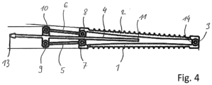
- FIG 4 the wheel chock is shown in its folded position.
- the locking surface 4 is pulled out relative to the base surface 1 and wheel surface 2, so that its end 11 is away from the stop 14 on the hinge 3.
- the support beams 5 and 6 extend approximately parallel to the locking surface 4, with the joints 7 and 8 resting on the locking surface 4.
- the bottom surface 1 and the wheel surface run at least approximately parallel to each other.
- the wheel chock is in a folded, flat state where it can be easily stored and stored on top of other folded wheel chocks.
Landscapes
- Engineering & Computer Science (AREA)
- Mechanical Engineering (AREA)
- Transportation (AREA)
- Aviation & Aerospace Engineering (AREA)
- Health & Medical Sciences (AREA)
- Public Health (AREA)
- Auxiliary Methods And Devices For Loading And Unloading (AREA)
- Purses, Travelling Bags, Baskets, Or Suitcases (AREA)
- Legs For Furniture In General (AREA)
- Refuge Islands, Traffic Blockers, Or Guard Fence (AREA)
Description
- Die Erfindung betrifft einen Radkeil zum Blockieren eines stehenden Rades, der eine Bodenfläche zur Auflage auf einem Boden und eine Radfläche zur Anlage am Rad aufweist, wobei die Radfläche zum Blockieren des Rades gewinkelt zur Bodenfläche vorgesehen ist.
- Zum Blockieren der Räder eines Fahrzeugs oder auch eines Flugzeugs ist es bekannt einen Keil zwischen wenigstens einem der Räder und dem Boden einzuklemmen, so dass das Rad blockiert und am Rollen gehindert ist. Derartige Keile werden auch Radschuh genannt. Es gibt unterschiedliche Dimensionen von Radkeilen, die sich am Einsatzgebiet des Radkeils orientieren, insbesondere an der Grösse des Rades, das blockiert werden soll. Für eine verbesserte Sicherung des Fahr- oder Flugzeugs werden Radkeile oftmals an gegenüberliegenden Seiten eines Rades und an mehreren Rädern vorgesehen.
- Die Radkeile müssen einer grossen Krafteinwirkung standnhalten, wenn eine Kraft vom Fahrzeug oder Flugzeug über das Rad auf den Radkeil übertragen wird. Sie sind daher oftmals schwer und klobig, so dass sie nur bedingt transportiert und verstaut werden können. Insbesondere wenn mehrere Radkeile zur Sicherung des Fahr- oder Flugzeugs verwendet werden, beanspruchen die Radkeile beim Verstauen viel Platz
- Aus der
DE 202008008588 ist zum Beispiel ein Radkeil bekannt, der überwiegend aus Kunststoff gefertig ist. Für eine zuverlässige Sicherung des Keils sind Teilbereiche jedoch aus Metall gefertigt, so dass der Gewichtsvorteil des Kunststoffs reduziert wird. Der Radkeil ist wie üblich als dreieckförmiger Klotz ausgebildet und verbraucht daher bei der Lagerung viel Stauraum. - Weitere Beispiele von Radkeilen sind aus
DE 633 272 C ,FR 795 805 A US 2 240 512 A undUS 2 816 627 A bekannt. - Es ist eine Aufgabe der vorliegenden Erfindung, einen Radkeil zur Verfügung zu Stellen, der ein zuverlässiges Blockieren eines Rades ermöglicht, bei der Lagerung wenig Platz beansprucht, einfach in der Handhabung ist und eine robuste Bauweise aufweist.
- Diese Aufgabe wird erfindungsgemäss durch einen Radkeil nach Anspruch 1 gelöst. Vorteilhafte Ausgestaltungen und unterschiedliche Ausführungsformen der Erfindung gehen aus den Unteransprüchen hervor.
- Ein Radkeil zum Blockieren eines stehenden Rades nach der vorliegenden Erfindung umfasst eine Bodenfläche zur Auflage auf einem Boden, z. B. einer Strasse, und eine Radfläche zur Anlage am zu blockierenden Rad. Erfindungsgemäss sind Radfläche und Bodenfläche über ein Scharnier miteinander verbunden, so dass der Radkeil faltbar ausgestaltet ist, d. h. Radfläche und Bodenfläche können zusammengeklappt werden. In einer Gebrauchsstellung ist der Radkeil aufgefaltet und Radfläche und Bodenfläche sind zum Blockieren des Rades gewinkelt zueinander fixiert. In einer Faltposition sind Radfläche und Bodenfläche zusammengeklappt und liegen zumindest annähernd parallel aufeinander.
- Erfindungsgemäss ist eine Arretiereinrichtung an der Bodenfläche und/oder der Radfläche derart beweglich angeordnet, dass sie in einer Arretierstellung Bodenfläche und Radfläche in einem aufgefalteten, gewinkelten Zustand arretiert und in einer Faltposition des Radkeils Bodenfläche und Radfläche zum Zusammenfalten frei gibt.
- Durch das Zusammenklappen kann das Volumen des Radkeils deutlich reduziert werden, so dass sein Platzbedarf bei der Lagerung reduziert ist. Ferner können mehrere Radkeile in der flachen Faltposition aufeinander gestapelt werden. Im Einsatz zum Blockieren eines Rades sind die Radkeile durch die Arretiereinrichtung sicher in ihrer Keilform fixiert und bieten eine zuverlässige Blockierung des Rades.
- Radfläche und Bodenfläche sind vorzugsweise als starre ebene Platten ausgebildet, so dass sie im gefalteten Zustand aufeinander zu liegen kommen können. Vorteilhaft sind Radfläche und Bodenfläche identisch ausgebildet, sodass die Flächen nur durch ihre Funktion identifiziert sind. Durch einfaches Umdrehen des Radkeils werden somit Boden- und Radfläche vertauscht. Grundsätzlich ist es aber auch möglich, dass die Platten eine leichte Wölbung aufweisen. Insbesondere bei der Radfläche kann damit die Anlage am Rad verbessert werden.
- In einer Ausführungsform weist die Arretiereinrichtung wenigstens einen Stützträger auf, der gelenkig an Boden- oder Radfläche angeordnet ist und in einer Arretierstellung die Bodenfläche und die Radfläche gewinkelt zueinander abstützt. Der Stützträger kann sich dabei an der gegenüberliegenden Fläche abstützen, also z. B. an der Radfläche, wenn der Stützträger an der Bodenfläche angeordnet ist. Alternativ kann sich der Stützträger an einer Fläche eines zusätzlichen Bauteils abstützen. Zur Sicherung in der Arretierstellung kann der Stützträger lösbar an der Fläche fixiert werden. Beispielsweise kann ein Anschlag oder eine Steck- oder Schnappfixierung vorgesehen werden.
- In einer weiteren Ausgestaltung des erfindungsgemässen Radkeils weist die Arretiereinrichtung eine starre Arretierfläche und wenigstens einen Stützträger auf. Die Arretierfläche, als zusätzliches Bauteil zu Rad- und Bodenfläche, kann beispielsweise in Form einer Platte oder eines Stab ausgebildet sein. Der Stützträger ist erfindunggemäß an seinem einem Ende gelenkig an der Arretierfläche und an seinem anderen Ende gelenkig an Boden- bzw. Radfläche gelagert. In einer Faltposition von Boden- und Radfläche verlaufen die Arretierfläche und vorzugsweise auch der Stützträger zumindest annähernd parallel zu Boden- bzw. Radfläche. In der Arretierstellung hingegen sind Arretierfläche, Stützträger und Boden- bzw. Radfläche dreieckförmig angeordnet, d. h. sie spannen einen Keil auf. Es wird betont, dass die Arretierfläche nicht direkt an der Radfläche oder der Bodenfläche angebracht ist, sondern nur über den Stützträger verbunden ist. Der Stützträger dient als Schwenkarm, mit dem die Arretierfläche relativ zu Boden- und Radfläche beweglich ist. Dabei kann die Arretierfläche von Rad- bzw. Bodenfläche abgehoben und gleichzeitig parallel dazu bewegt werden. Zusätzlich dient der Stützträger zum Abstützen der Arretierfläche in einer Arretierstellung. Dadurch wird die Beweglichkeit des Radkeils verbessert und dieser kann in einfacher Weise zusammengefaltet werden.
- Erfindungsgemäß schlägt die Arretierfläche in der Arretierstellung mit einem Ende an einem Anschlag an Boden- bzw. Radfläche an; vorzugweise an der Boden- bzw. Radfläche an der auch der Stützträger beweglich gelagert ist. Dabei bilden Arretierfläche, Stützträger und Boden- bzw. Radfläche ein Dreieck. In der Faltposition ist dieses Ende der Arretierfläche von dem Anschlag entfernt und der Radkeil kann zusammengeklappt werden. Erfindungsgemäß bildet das Scharnier zwischen Bodenfläche und Radfläche den Anschlag. Somit sind keine zusätzlichen baulichen Massnahmen erforderlich, um den Anschlag zu realisieren.
- In einer bevorzugten Ausführungsform eines Radkeils nach der vorliegenden Erfindung sind zwei Stützträger vorgesehen, die jeweils mit einem Ende an gegenüberliegenden Seiten einer Arretierfläche gelagert sind. Ein erster Stützträger ist mit seinem anderen Ende an der Bodenfläche und ein zweiter Stützträger mit seinem anderen Ende an der Radfläche gelagert. Die Anordnung bildet somit eine symmetrische, spiegelbildliche Geometrie um die Arretierfläche. Wie vorher erwähnt, können vorteilhaft die Bodenfläche und die Radfläche identisch sein, so dass sie miteinander austauschbar sind. Die Stützträger haben die gleiche Länge, so dass die Arretierfläche mittig zwischen Rad- und Bodenfläche angeordnet ist. Durch die gelenkige Verbindung der Arretierfläche mit der Radfläche und der Bodenfläche mittels der Stützträger kann die Arretierfläche in Längsrichtung zu Rad- und Bodenfläche aus diesen herausgezogen und in diese hineingeschoben werden. Dabei werden Rad- und Bodenfläche schirmartig aufgespannt oder zusammengeklappt. Zum Aufspannen wird die Arretierfläche zwischen die Rad- und Bodenfläche hineingeschoben bis sie am Scharnier anschlägt. In dieser Stellung sind Rad- und Bodenfläche in aufgefaltetem Zustand arretiert und der Radkeil ist einsatzbereit, um ein Rad zu blockieren.
- In einer vorteilhaften Ausgestaltung des Radkeils ist die Geometrie zwischen Bodenfläche, Radfläche und Stützträger derart ausgelegt, dass eine Last eines Rades, das gegen die Radfläche drückt, den Radkeil in seine Arretierstellung presst. Die Radlast wirkt grundsätzlich in Richtung der Normalen der Radfläche, d. h. senkrecht zur Radfläche. Die Längen von Stützträger, Bodenfläche und Radfläche sind also derart ausgelegt, dass die Lastkraft in eine Kraft umgelenkt wird, welche den Stützträger, bzw. die Arretierfläche, in die Arretierstellung drückt, insbesondere die Arretierfläche gegen ihren Anschlag presst. Ein Kraftvektor in Richtung der Normalen der Radfläche schliesst also mit dem wenigstens einen Stützträger einen Winkel derart ein, dass die Arretiereinrichtung in eine Arretierstellung gezwungen ist.
- Bei der oben geschilderten Ausführungsform mit zwei symmetrisch an der Arretierfläche gelagerten Stützträgern ist hierfür ein Winkel zwischen den Stützträgern und der Arretierfläche grösser als 90° vorgesehen. Dadurch wird der Kraftvektor in Richtung der Normalen der Radfläche wenigstens teilweise in eine Schubkraft transformiert, welche die Arretierfläche in den Anschlag schiebt, in diesem Fall gegen das Scharnier zwischen Radfläche und Bodenfläche. Die Radlast dient damit als zusätzliche Sicherung des Radkeils in seiner Keilposition, so dass ein ungewolltes Zusammenklappen verhindert wird.
- In einer Variante eines Radkeils nach der Erfindung besteht wenigstens die Radfläche und vorzugsweise auch die Bodenfläche aus Aluminium. Besonders bevorzugt besteht der gesamte Radkeil aus Aluminium. Aluminium erlaubt eine leichte Bauweise. Darüber hinaus ermöglicht Aluminium das Ableiten von statischer Ladung von Fahrzeugen zum Boden. Ferner entsteht keine Funkenbildung, falls der Radkeil über den Boden reibt. Weiter ist Aluminium unempfindlich gegen Verschmutzungen, wie etwa Öle, Kerosin, Enteisungsflüssigkeiten, etc. die auf dem Boden vorhanden sein können.
- Alternative kann der Radkeil aus einem rostfreien Metall oder einem Kompositwerkstoff besteht. Rostfreie Metalle haben den Vorteil, dass sie sehr robust und langlebig sind. Heutige Kompositwerkstoffe weisen eine ausreichende Steifigkeit auf, um ein Rad zu blockieren und ermöglichen zudem ein geringes Gewicht des Radkeils.
- In einer Ausführungsform weist der Radkeil vorteilhaft auf der Bodenfläche Spikes aus Hartmetall auf, um ein Wegrutschen auf glattem oder vereistem Untergrund zu verhindern.
- Bei noch einer weiteren Ausführungsform des Radkeils nach der Erfindung kann die Arretierfläche an ihrem dem Anschlagende gegenüberliegenden Ende einen Griff aufweisen. Die Länge der Arretierfläche ist derart abgestimmt, dass der Griff in der Arretierstellung und in der Faltposition über die Bodenfläche und die Radfläche hinaussteht. Somit ist der Griff zur Betätigung der Arretierfläche sowohl in gefaltetem Zustand als auch in aufgeklapptem Zustand des Radkeils zugänglich. Mit dem Griff kann die Arretierfläche in einfacher Weise aus der Arretierstellung, d. h. vom Anschlag weg, gezogen werden. Ein Verkeilen kann damit schnell gelöst und der Radkeil kann verstaut werden. Umgekehrt kann der Radkeil durch Vorschieben am Griff in Richtung unter das Rad im aufgefalteten Zustand gesichert werden. Durch das Vorschieben am Griff wird die Arretierfläche gegen ihren Anschlag gedrängt.
- In einer weiteren vorteilhaften Ausführungsform umfasst der Radkeil an der Arretierfläche eine lösbare Sicherungsverbindung, die sich zur Sicherung der Arretierfläche in der Arretierstellung von der Arretierfläche in Richtung des Anschlags erstreckt. Vorzugsweise ist die Sicherungsverbindung als eine elastische Zugverbindung ausgebildet, beispielsweise als Gummiband. Mit der Zugkraft der gespannten Sicherungsverbindung kann die Arretierfläche gegen den Anschlag gepresst werden. Die Sicherungsverbindung kann am Radkeil selbst befestigt werden, beispielsweise im Bereich des Anschlags oder des Scharniers. Vorteilhaft kann die Sicherungsverbindung auch am Rad befestigt werden, das durch den Radkeil blockiert werden soll.
- Vorzugsweise wird ein Paar von Radkeilen vorgesehen, wobei jeweils ein Radkeil an gegenüberliegenden Seiten eines Rads positioniert wird. In diesem Fall kann sich die Sicherungsverbindung von einem Radkeil zum gegenüberliegenden erstrecken und an diesem befestigt werden. Vorteil hat kann dabei die selbe Sicherungsverbindung für beide Radkeile verwendet werden, indem sie sich von einer Arretierfläche des einen Radkeils zur Arretierfläche des gegenüberliegenden Radkeils erstreckt. Dadurch können beide Radkeile gleichzeitig in ihrer Arretierstellung gesichert werden und sie können auch gleichzeitig aus dieser Sicherung gelöst werden.
- Die Erfindung wird im Folgenden anhand der Figuren dargestellt, die lediglich zur Erläuterung dienen sollen und nicht einschränkend auszulegen sind. In den Zeichnungen zeigen:
- Fig. 1
- eine dreidimensionale Darstellung einer Ausführungsform eines Radkeils nach der vorliegenden Erfindung in aufgefaltetem Zustand,
- Fig. 2
- eine Explosionsdarstellung des Radkeils aus
Figur 1 , - Fig. 3
- eine Seitenansicht des Radkeils aus
Figur 1 und - Fig. 4
- eine Darstellung des Radkeils aus
Figur 1 in zusammengefaltetem Zustand. - In
Figur 1 ist eine Ausführungsform eines faltbaren Radkeils zum Blockieren eines stehenden Rades nach der vorliegenden Erfindung gezeigt. Der Radkeil weist eine Bodenfläche 1 und eine Radfläche 2 auf, die an einem Ende mittels eines Scharniers 3 verbunden sind. Mit dem Scharnier 3 können die Bodenfläche 1 und die Radfläche 2 relativ zueinander aufgeklappt werden. Das Scharnier ist derart ausgelegt, dass die inneren Flächen von Bodenfläche 1 und Radfläche 2 aufeinander zu liegen kommen können. - Weiter weist der Radkeil eine Arretiereinrichtung auf, die an der Bodenfläche oder der Radfläche beweglich angeordnet ist. Die Arretiereinrichtung umfasst eine Arretierfläche 4, einen ersten Stützträger 5 und einen zweiten Stützträger 6. Die Stützträger 5 und 6 sind in dieser Variante als starre Stützplatten ausgebildet. Der erste Stützträger 5 ist mit einem Gelenk 7 schwenkbar an der Bodenfläche 1 gelagert und zwar am Ende, das dem Scharnier 3 gegenüberliegt. In symmetrischer Weise ist der zweite Stützträger 6 mit einem Gelenk 8 schwenkbar an der Radfläche 2 gelagert, wiederum am Ende, das dem Scharnier 3 gegenüberliegt. An ihren den Gelenken 7 und 8 gegenüberliegenden Enden sind der erste Stützträger 5 und der zweite Stützträger 6 jeweils über Gelenke 9 und 10 an der Arretierfläche 4 gelagert. Die Gelenke 9 und 10 sind an gegenüberliegenden Seiten der Arretierfläche 4 vorgesehen. Eine Verbindung der Arretierfläche 4 mit der Bodenfläche 1 oder der Radfläche 2 ist nicht vorgesehen.
- Durch die Stützträger 5 und 6 und die Gelenke 7, 8, 9 und 10 ist die Bewegung der Arretierfläche 4 relative zu Bodenfläche 1 und Radfläche 2 jedoch festgelegt. Die Arretierfläche 4 kann parallel zu Bodenfläche 1 und Radfläche 2 verlagert werden und die Stützträger 5 und 6 relative dazu verschwenkt werden. Ein erstes Ende 11 der Arretierfläche 4 ragt dabei in Richtung des Scharniers 3 zwischen Bodenfläche 1 und Radfläche 2. Am zweiten, gegenüberliegenden Ende 12 der Arretierfläche 4 ist ein Griff 13 vorgesehen, mit dem die Arretierfläche 4 relative zu Bodenfläche 1 und Radfläche 2 manuell bewegt werden kann.
- In
Figur 1 ist der Radkeil in einer Arretierstellung gezeigt, in der die Bodenfläche 1 und die Radfläche 2 in einem aufgefalteten, gewinkelten Zustand arretiert sind. Bei dieser Variante des Radkeils wird die Arretierung dadurch erzielt, dass das erste Ende 11 der Arretierfläche 4 gegen das Scharnier 3 anschlägt, welche Bodenfläche 1 und Radfläche 2 verbindet. Das Scharnier bildet somit auf seiner Innenseite zwischen Bodenfläche und Radfläche einen Anschlag 14 für die Arretierfläche 4. Die steifen Stützträger 5 und 6 spreizen die Bodenfläche 1 und die Radfläche 2 am gegenüberliegenden Ende 12 der Arretierfläche auseinander, sodass eine Keilform entsteht. Auf die Geometrie des Radkeils wird inFigur 3 näher eingegangen. -
Figur 2 zeigt eine teilweise Explosionsdarstellung des Radkeils ausFigur 1 aus der die einzelnen Bauteile ersichtlich sind. Dabei ist der Bereich der Radfläche 2 als Explosionsansicht gezeigt und der Bereich der Bodenfläche 1 in zusammengebautem Zustand dargestellt, wie inFigur 1 . - Bodenfläche 1 und Radfläche 2 sind im Wesentlichen identisch ausgestaltet. Sie sind als starre Aluminiumplatten vorgesehen und weisen an ihren als Aussenflächen des Radkeils vorgesehenen Seiten eine Riffelung auf. Die Riffelung unterstützt einen sicheren Halt am Boden und an einem zu blockierenden Rad. Das Scharnier 3 ist als Stabscharnier mit einem Stab 15 vorgesehen. An einem Enden von Bodenfläche 1 und Radfläche 2 sind Scharnierblöcke 16a und 16b mit einer Lagerdurchführung vorgesehen, die als Lagerung für den Stab 15 dienen. In zusammengebautem Zustand greifen die Scharnierblöcke 16a und 16b zwischen einander und der Stab 15 verläuft durch die Lagerdurchführungen der Scharnierblöcke 16a und 16b. Der Stab 15 wird mittels Fixierschrauben 17 in den Scharnierblöcken 16a und 16b fixiert.
- Für die Gelenke 7 und 8 sind am anderen Ende der Bodenfläche 1 und der Radfläche 2 Gelenkblöcke 18 vorgesehen, die mit Gelenkblöcken 19 am ersten Stützträger 5, bzw. am zweiten Stützträger 6, zusammenwirken. Die Gelenkblöcke 18 und 19 weisen jeweils Lagerdurchführungen auf. Ein Stab 20 verläuft durch die Lagerdurchführungen und verbindet die Gelenkblöcke 18 und 19, so dass die Gelenke 8 und 7 entstehen. Weiter weisen die Stützträger 5 und 6 an ihren zur Arretierfläche 4 ragenden Ende Gelenkblöcke 21 auf. Die Arretierfläche 4 weist zu beiden Seiten Gelenkblöcke 22 auf, die zwischen die Gelenkblöcke 21 greifen können. Die Gelenkblöcke 21 und 22 weisen wiederum Lagerdurchführungen auf. Durch einen Stab 23 werden die Gelenkblöcke 21 und 22 verbunden, so dass die Gelenke 9 und 10 entstehen. Die Stäbe 20 und 23 werden wiederum durch Fixierschrauben 17 in den Gelenklagern der Gelenkblöcke gesichert.
- In
Figur 3 ist die Geometrie des Radkeils in einer Arretierstellung in aufgefaltetem Zustand gezeigt. Ein Kraftvektor F zeigt die Krafteinwirkung von einem Rad auf die Radfläche 2 des Radkeils. Der Kraftvekotr F wirkt in Richtung der Normalen der Radfläche 2. Er schliesst mit dem Stützträger 6 einen Winkel derart ein, dass die Arretierfläche 4 in die Arretierstellung gezwungen ist, in der ihr Ende 11 gegen den Anschlag 14 stösst. Hierfür ist ein Winkel α zwischen Kraftvektor F und dem Stützträger 6 auf der Seite des Arretierflächenendes 11 kleiner als 180°. Die Kraft des Kraftvektor F erzeugt im Stützträger 6 eine Kraftkomponente K, die auf die Arretierfläche 4 einwirkt. Der Winkel β zwischen dem Stützträger 6, bzw. der Kraftkomponente K, und der Arretierfläche 4 ist grösser als 90°. Daher wird die Kraftkomponente K in eine Vorschubkraft V transformiert, welche die Arretierfläche 4 in Richtung des Anschlags 14 presst. Durch eine Belastung der Radfläche 2 wird deshalb die Arretiereinrichtung des Radkeils in der Arretierstellung gesichert. Ein analoger Kraftverlauf entsteht zwischen der Bodenfläche 1, dem Stützträger 5 und der Arretierfläche 4. - In der vorliegenden Ausführungsform weisen die Bodenfläche 1 und die Radfläche 2 z. B. eine Länge von 220 mm und die Arretierfläche 4 eine Länge von 234,8 mm auf. Der Winkel α beträgt 148° und der Winkel β 99.5°. Diese Werte sind jedoch lediglich beispielhaft, es sind auch andere Winkel unter 180° für α und über 90° für β und andere Längen möglich.
- In
Figur 4 ist der Radkeil in seiner Faltposition gezeigt. Die Arretierfläche 4 ist relative zu Bodenfläche 1 und Radfläche 2 herausgezogen, so dass ihr Ende 11 vom Anschlag 14 am Scharnier 3 entfernt ist. Die Stützträger 5 und 6 erstrecken sich annähernd parallel zur Arretierfläche 4, wobei die Gelenke 7 und 8 auf der Arretierfläche 4 aufliegen. Die Bodenfläche 1 und die Radfläche verlaufen zumindest annähernd parallel zu einander. Der Radkeil ist in einem zusammen geklappten, flachen Zustand, in dem er leicht verstaut und auf anderen zusammen geklappten Radkeilen gelagert werden kann. - Es wird betont, dass neben der in den Figuren gezeigten Ausführungsform auch andere Ausgestaltungen des Radkeils mit den Merkmalen der Erfindung möglich sind. Beispielsweise kann nur ein Stützträger vorgesehen sein, der in der beschriebenen Weise zwischen Boden- oder Radfläche und der Arretierfläche gelagert ist. Die jeweils andere von Boden- oder Radfläche kann dann z. B. gleitend auf der Arretierfläche aufliegen. Die Arretierfläche kann ebenfalls zwischen Boden- und Arbeitsfläche verschoben und in Anschlag mit dem Scharnier gebracht werden. Allerdings ist der Keilwinkel bei dieser Ausgestaltung nur halb so gross, wie in der gezeigten Ausführungsform. Ferner muss der Anschlag nicht am Scharnier ausgebildet sein. Es können z. B. auch Kanten auf der Innenseite von Boden- oder Radfläche vorgesehen sein, die als Anschlag für das Ende der Arretierfläche dienen können. Es ist denkbar eine Serie von Kanten vorzusehen, sodass ein Winkel des Radkeils variabel ist, je nachdem an welcher Kante die Arretierfläche arretiert wird. Weitere Variationen eine Radkeils nach der Erfindung sind denkbar.
-
- 1
- Bodenfläche
- 2
- Radfläche
- 3
- Scharnier
- 4
- Arretierfläche
- 5
- erster Stützträger
- 6
- zweiter Stützträger
- 7
- Gelenk
- 8
- Gelenk
- 9
- Gelenk
- 10
- Gelenk
- 11
- erstes Ende Arretierfläche
- 12
- zweites Ende Arretierfläche
- 13
- Griff
- 14
- Anschlag
- 15
- Stab
- 16
- Scharnierblöcke
- 17
- Fixierschrauben
- 18
- Gelenkblöcke
- 19
- Gelenkblöcke
- 20
- Stab
- 21
- Gelenkblöcke
- 22
- Gelenkblöcke
- 23
- Stab
- K
- Kraftkomponente
- V
- Vorschub
- F
- Kraftvektor
Claims (11)
- Radkeil zum Blockieren eines stehenden Rades, der eine Bodenfläche (1) zur Auflage auf einem Boden und eine Radfläche (2) zur Anlage am Rad aufweist, wobei die Radfläche (2) zum Blockieren des Rades gewinkelt zur Bodenfläche (1) vorgesehen ist und Bodenfläche (1) und Radfläche (2) über ein Scharnier (3) miteinander verbunden und faltbar ausgestaltet sind, wobei- eine Arretiereinrichtung an der Bodenfläche (1) und/oder der Radfläche (2) beweglich angeordnet ist, die in einer Arretierstellung Bodenfläche (1) und Radfläche (2) in einem aufgefalteten, gewinkelten Zustand arretiert,- wobei die Arretiereinrichtung eine starre Arretierfläche (4) und wenigstens einen Stützträger (5) aufweist, der an einem Ende gelenkig an der Arretierfläche (4) und am anderen Ende gelenkig an Boden- bzw. Radfläche (1; 2) gelagert ist, so dass in einer Faltposition die Arretierfläche (4) zumindest annähernd parallel zu Boden- bzw. Radfläche (1; 2) und in der Arretierstellung Arretierfläche (4), Stützträger (5) und Boden- bzw. Radfläche (1; 2) dreieckförmig angeordnet sind, dadurch gekennzeichnet,- dass das Scharnier (3) zwischen Bodenfläche (1) und Radfläche (2) einen Anschlag (14) bildet, so dass in der Arretierstellung die Arretierfläche (4) mit einem Ende (11) am Scharnier (3) anschlägt und in der Faltposition dieses Ende (11) vom Scharnier (3) entfernt ist.
- Radkeil nach Anspruch 1, dadurch gekennzeichnet, dass die Arretiereinrichtung wenigstens einen Stützträger (5) aufweist, der gelenkig an Boden- oder Radfläche (1; 2) angeordnet ist und in einer Arretierstellung die Bodenfläche (1) und die Radfläche (2) gewinkelt zueinander abstützt.
- Radkeil nach einem der vorhergehenden Ansprüche, dadurch gekennzeichnet, dass zwei Stützträger (5, 6) vorgesehen sind, die jeweils mit einem Ende an gegenüberliegenden Seiten der Arretierfläche (4) gelagert sind, und ein erster Stützträger (5) mit seinem anderen Ende an der Bodenfläche (1) und ein zweiter Stützträger (6) mit seinem anderen Ende an der Radfläche (2) gelagert sind.
- Radkeil nach einem der vorhergehenden Ansprüche, dadurch gekennzeichnet, dass ein Kraftvektor (F) in Richtung der Normalen der Radfläche (2) mit dem wenigstens einen Stützträger (6) einen Winkel derart einschliesst, dass die Arretiereinrichtung in eine Arretierstellung gezwungen ist.
- Radkeil nach Anspruch 3 und 4, dadurch gekennzeichnet, dass in der Arretierstellung ein Winkel zwischen den Stützträgern und der Arretierfläche grösser als 90° ist.
- Radkeil nach einem der vorhergehenden Ansprüche, dadurch gekennzeichnet, dass wenigstens die Radfläche (2) aus Aluminium besteht und vorzugsweise der gesamte Radkeil aus Aluminium besteht.
- Radkeil nach einem der vorhergehenden Ansprüche, dadurch gekennzeichnet, dass der Radkeil aus einem rostfreien Metall oder einem Kompositwerkstoff besteht.
- Radkeil nach einem der vorhergehenden Ansprüche, dadurch gekennzeichnet, dass der Radkeil auf der Bodenfläche (1) Spikes aufweist, vorzugsweise Spikes aus Hartmetall.
- Radkeil nach einem der vorhergehenden Ansprüche, dadurch gekennzeichnet, dass die Arretierfläche (4) an ihrem dem Anschlagende (11) gegenüberliegenden Ende (12) einen Griff (13) aufweist, der in der Arretierstellung und in der Faltposition über die Bodenfläche (1) und die Radfläche (2) hinaussteht.
- Radkeil nach einem der vorhergehenden Ansprüche, dadurch gekennzeichnet, dass die Arretierfläche (4) eine lösbare Sicherungsverbindung umfasst, die sich zur Sicherung der Arretierfläche in der Arretierstellung von der Arretierfläche (4) in Richtung des Anschlags (14) erstreckt.
- Radkeil nach Anspruch 10, dadurch gekennzeichnet, dass die Sicherungsverbindung eine elastische Zugverbindung ist.
Applications Claiming Priority (2)
| Application Number | Priority Date | Filing Date | Title |
|---|---|---|---|
| CH01580/16A CH713192A1 (de) | 2016-12-02 | 2016-12-02 | Radkeil zum Blockieren eines stehenden Rades. |
| PCT/EP2017/081115 WO2018100130A1 (de) | 2016-12-02 | 2017-12-01 | Radkeil zum blockieren eines stehenden rades |
Publications (4)
| Publication Number | Publication Date |
|---|---|
| EP3548344A1 EP3548344A1 (de) | 2019-10-09 |
| EP3548344B1 true EP3548344B1 (de) | 2024-02-07 |
| EP3548344C0 EP3548344C0 (de) | 2024-02-07 |
| EP3548344B8 EP3548344B8 (de) | 2024-07-24 |
Family
ID=57994992
Family Applications (1)
| Application Number | Title | Priority Date | Filing Date |
|---|---|---|---|
| EP17808447.1A Active EP3548344B8 (de) | 2016-12-02 | 2017-12-01 | Radkeil zum blockieren eines stehenden rades |
Country Status (4)
| Country | Link |
|---|---|
| US (1) | US11097698B2 (de) |
| EP (1) | EP3548344B8 (de) |
| CH (1) | CH713192A1 (de) |
| WO (1) | WO2018100130A1 (de) |
Families Citing this family (4)
| Publication number | Priority date | Publication date | Assignee | Title |
|---|---|---|---|---|
| USD987541S1 (en) | 2019-08-07 | 2023-05-30 | Motis Brands, Inc. | Wheel chock |
| US12297062B1 (en) | 2020-09-21 | 2025-05-13 | The Chamberlain Group Llc. | System and method for restraining a vehicle proximate a loading dock |
| US20220234551A1 (en) * | 2021-01-22 | 2022-07-28 | Adam S. Laudick | Multi-functional wheel chock |
| US11796018B1 (en) * | 2022-04-11 | 2023-10-24 | Toyota Motor Engineering & Manufacturing North America, Inc. | Vehicle wheel torque braces and methods of inhibiting vehicle wheel rotation |
Family Cites Families (10)
| Publication number | Priority date | Publication date | Assignee | Title |
|---|---|---|---|---|
| US1082807A (en) * | 1912-11-09 | 1913-12-30 | Herbert Fleetwood Holworthy | Wheel-scotch. |
| DE633272C (de) * | 1933-09-08 | 1936-07-23 | Jean Krug Basse | Zusammenklappbarer Auffahrkeil |
| FR795805A (fr) * | 1934-12-26 | 1936-03-23 | Jacottet Paul Sa | Cale repliable, plus particulièrement applicable aux roues d'avions et de tous autres véhicules |
| FR806221A (fr) * | 1935-09-05 | 1936-12-10 | Cale pliante pour avions | |
| US2240512A (en) * | 1940-07-10 | 1941-05-06 | Jr Otto Morgensen | Wheel chock |
| CH300232A (de) * | 1952-04-01 | 1954-07-15 | Thalmann Paul | Mehrzweckgerät. |
| US2816627A (en) * | 1954-01-21 | 1957-12-17 | Calumet Steel Castings Corp | Retractable wheel chock |
| US3973651A (en) * | 1972-03-15 | 1976-08-10 | Humphrey Thompson Enterprises Limited | Vehicle chock |
| DE2249211C2 (de) * | 1972-10-07 | 1974-10-10 | Jean Walterscheid Gmbh, 5204 Lohmar | Bremskeil für Radfahrzeuge |
| ITMI20070227U1 (it) | 2007-06-27 | 2008-12-28 | Reco S R L | Cuneo fermaruota per veicolo industriale |
-
2016
- 2016-12-02 CH CH01580/16A patent/CH713192A1/de not_active Application Discontinuation
-
2017
- 2017-12-01 US US16/465,173 patent/US11097698B2/en active Active
- 2017-12-01 EP EP17808447.1A patent/EP3548344B8/de active Active
- 2017-12-01 WO PCT/EP2017/081115 patent/WO2018100130A1/de not_active Ceased
Also Published As
| Publication number | Publication date |
|---|---|
| EP3548344A1 (de) | 2019-10-09 |
| WO2018100130A1 (de) | 2018-06-07 |
| US11097698B2 (en) | 2021-08-24 |
| EP3548344B8 (de) | 2024-07-24 |
| US20190329742A1 (en) | 2019-10-31 |
| EP3548344C0 (de) | 2024-02-07 |
| CH713192A1 (de) | 2018-06-15 |
Similar Documents
| Publication | Publication Date | Title |
|---|---|---|
| DE69207315T2 (de) | Tragbare Ständer oder Stative | |
| EP3766759B1 (de) | Klappwagen | |
| DE3341403C2 (de) | ||
| EP3548344B1 (de) | Radkeil zum blockieren eines stehenden rades | |
| EP1544379B1 (de) | Klemmvorrichtung | |
| DE102012012134A1 (de) | Sicherheitssitzvorrichtung | |
| CH656437A5 (de) | Vorrichtung zum einstellen der relativen lage zweier bauteile. | |
| DE102014014427A1 (de) | Stielgeführtes Werkzeug und Stützvorrichtung zum Abstellen eines stielgeführten Werkzeuges | |
| DE102019107821A1 (de) | Rollcontainer | |
| DE19819011A1 (de) | Einstellbare Halteeinrichtung für Bordcomputer in Kraftfahrzeugen, insbesondere für Laptop- oder Notebook-Computer | |
| DE3737651A1 (de) | Vorrichtung fuer eine unterfalt-ladebordwand | |
| DE2444021B2 (de) | Runge für Ladeplattformen von Fahrzeugen | |
| EP3800143A1 (de) | Vorrichtung zum lagegenauen positionieren einer transportpalette | |
| DE202009007138U1 (de) | Klappmechanismus für Rollfahrzeug | |
| DE69711624T2 (de) | Lastträger | |
| EP3868636A1 (de) | Tretroller | |
| EP1038465A2 (de) | Schirmständer | |
| DE2707926C3 (de) | Fersenbindung | |
| EP1619079A2 (de) | Vorrichtung zum Tragen von Lasten am Äusseren eines Fahrzeuges | |
| DE10023171C2 (de) | Türfuttermontagesystem | |
| DE102013217866A1 (de) | Gelenkanordnung für eine Klappbake und Klappbake | |
| DE8809320U1 (de) | Vorrichtung zum Haltern bzw. Sichern von Gegenständen | |
| DE3623752A1 (de) | Bremskeil fuer rollende koerper, insbesondere fuer fahrzeugraeder | |
| DE102024128744A1 (de) | Ladesicherungsvorrichtung | |
| DE3630304C1 (en) | Vertically adjustable podium |
Legal Events
| Date | Code | Title | Description |
|---|---|---|---|
| STAA | Information on the status of an ep patent application or granted ep patent |
Free format text: STATUS: UNKNOWN |
|
| STAA | Information on the status of an ep patent application or granted ep patent |
Free format text: STATUS: THE INTERNATIONAL PUBLICATION HAS BEEN MADE |
|
| PUAI | Public reference made under article 153(3) epc to a published international application that has entered the european phase |
Free format text: ORIGINAL CODE: 0009012 |
|
| STAA | Information on the status of an ep patent application or granted ep patent |
Free format text: STATUS: REQUEST FOR EXAMINATION WAS MADE |
|
| 17P | Request for examination filed |
Effective date: 20190702 |
|
| AK | Designated contracting states |
Kind code of ref document: A1 Designated state(s): AL AT BE BG CH CY CZ DE DK EE ES FI FR GB GR HR HU IE IS IT LI LT LU LV MC MK MT NL NO PL PT RO RS SE SI SK SM TR |
|
| AX | Request for extension of the european patent |
Extension state: BA ME |
|
| DAV | Request for validation of the european patent (deleted) | ||
| DAX | Request for extension of the european patent (deleted) | ||
| STAA | Information on the status of an ep patent application or granted ep patent |
Free format text: STATUS: EXAMINATION IS IN PROGRESS |
|
| 17Q | First examination report despatched |
Effective date: 20221005 |
|
| GRAP | Despatch of communication of intention to grant a patent |
Free format text: ORIGINAL CODE: EPIDOSNIGR1 |
|
| STAA | Information on the status of an ep patent application or granted ep patent |
Free format text: STATUS: GRANT OF PATENT IS INTENDED |
|
| INTG | Intention to grant announced |
Effective date: 20231124 |
|
| GRAS | Grant fee paid |
Free format text: ORIGINAL CODE: EPIDOSNIGR3 |
|
| GRAA | (expected) grant |
Free format text: ORIGINAL CODE: 0009210 |
|
| STAA | Information on the status of an ep patent application or granted ep patent |
Free format text: STATUS: THE PATENT HAS BEEN GRANTED |
|
| AK | Designated contracting states |
Kind code of ref document: B1 Designated state(s): AL AT BE BG CH CY CZ DE DK EE ES FI FR GB GR HR HU IE IS IT LI LT LU LV MC MK MT NL NO PL PT RO RS SE SI SK SM TR |
|
| REG | Reference to a national code |
Ref country code: GB Ref legal event code: FG4D Free format text: NOT ENGLISH |
|
| REG | Reference to a national code |
Ref country code: CH Ref legal event code: EP |
|
| REG | Reference to a national code |
Ref country code: IE Ref legal event code: FG4D Free format text: LANGUAGE OF EP DOCUMENT: GERMAN |
|
| REG | Reference to a national code |
Ref country code: DE Ref legal event code: R096 Ref document number: 502017015815 Country of ref document: DE |
|
| REG | Reference to a national code |
Ref country code: CH Ref legal event code: PK Free format text: BERICHTIGUNGEN |
|
| U01 | Request for unitary effect filed |
Effective date: 20240305 |
|
| U07 | Unitary effect registered |
Designated state(s): AT BE BG DE DK EE FI FR IT LT LU LV MT NL PT SE SI Effective date: 20240312 |
|
| REG | Reference to a national code |
Ref country code: CH Ref legal event code: PK Free format text: BERICHTIGUNG B8 |
|
| PG25 | Lapsed in a contracting state [announced via postgrant information from national office to epo] |
Ref country code: IS Free format text: LAPSE BECAUSE OF FAILURE TO SUBMIT A TRANSLATION OF THE DESCRIPTION OR TO PAY THE FEE WITHIN THE PRESCRIBED TIME-LIMIT Effective date: 20240607 |
|
| PG25 | Lapsed in a contracting state [announced via postgrant information from national office to epo] |
Ref country code: GR Free format text: LAPSE BECAUSE OF FAILURE TO SUBMIT A TRANSLATION OF THE DESCRIPTION OR TO PAY THE FEE WITHIN THE PRESCRIBED TIME-LIMIT Effective date: 20240508 |
|
| RAP4 | Party data changed (patent owner data changed or rights of a patent transferred) |
Owner name: SATCOM CORPORATION SA |
|
| U1H | Name or address of the proprietor changed after the registration of the unitary effect |
Owner name: SATCOM CORPORATION SA; IT |
|
| PG25 | Lapsed in a contracting state [announced via postgrant information from national office to epo] |
Ref country code: RS Free format text: LAPSE BECAUSE OF FAILURE TO SUBMIT A TRANSLATION OF THE DESCRIPTION OR TO PAY THE FEE WITHIN THE PRESCRIBED TIME-LIMIT Effective date: 20240507 Ref country code: HR Free format text: LAPSE BECAUSE OF FAILURE TO SUBMIT A TRANSLATION OF THE DESCRIPTION OR TO PAY THE FEE WITHIN THE PRESCRIBED TIME-LIMIT Effective date: 20240207 |
|
| PG25 | Lapsed in a contracting state [announced via postgrant information from national office to epo] |
Ref country code: ES Free format text: LAPSE BECAUSE OF FAILURE TO SUBMIT A TRANSLATION OF THE DESCRIPTION OR TO PAY THE FEE WITHIN THE PRESCRIBED TIME-LIMIT Effective date: 20240207 |
|
| PG25 | Lapsed in a contracting state [announced via postgrant information from national office to epo] |
Ref country code: RS Free format text: LAPSE BECAUSE OF FAILURE TO SUBMIT A TRANSLATION OF THE DESCRIPTION OR TO PAY THE FEE WITHIN THE PRESCRIBED TIME-LIMIT Effective date: 20240507 Ref country code: NO Free format text: LAPSE BECAUSE OF FAILURE TO SUBMIT A TRANSLATION OF THE DESCRIPTION OR TO PAY THE FEE WITHIN THE PRESCRIBED TIME-LIMIT Effective date: 20240507 Ref country code: IS Free format text: LAPSE BECAUSE OF FAILURE TO SUBMIT A TRANSLATION OF THE DESCRIPTION OR TO PAY THE FEE WITHIN THE PRESCRIBED TIME-LIMIT Effective date: 20240607 Ref country code: HR Free format text: LAPSE BECAUSE OF FAILURE TO SUBMIT A TRANSLATION OF THE DESCRIPTION OR TO PAY THE FEE WITHIN THE PRESCRIBED TIME-LIMIT Effective date: 20240207 Ref country code: GR Free format text: LAPSE BECAUSE OF FAILURE TO SUBMIT A TRANSLATION OF THE DESCRIPTION OR TO PAY THE FEE WITHIN THE PRESCRIBED TIME-LIMIT Effective date: 20240508 Ref country code: ES Free format text: LAPSE BECAUSE OF FAILURE TO SUBMIT A TRANSLATION OF THE DESCRIPTION OR TO PAY THE FEE WITHIN THE PRESCRIBED TIME-LIMIT Effective date: 20240207 |
|
| PG25 | Lapsed in a contracting state [announced via postgrant information from national office to epo] |
Ref country code: PL Free format text: LAPSE BECAUSE OF FAILURE TO SUBMIT A TRANSLATION OF THE DESCRIPTION OR TO PAY THE FEE WITHIN THE PRESCRIBED TIME-LIMIT Effective date: 20240207 |
|
| PG25 | Lapsed in a contracting state [announced via postgrant information from national office to epo] |
Ref country code: PL Free format text: LAPSE BECAUSE OF FAILURE TO SUBMIT A TRANSLATION OF THE DESCRIPTION OR TO PAY THE FEE WITHIN THE PRESCRIBED TIME-LIMIT Effective date: 20240207 |
|
| PG25 | Lapsed in a contracting state [announced via postgrant information from national office to epo] |
Ref country code: SM Free format text: LAPSE BECAUSE OF FAILURE TO SUBMIT A TRANSLATION OF THE DESCRIPTION OR TO PAY THE FEE WITHIN THE PRESCRIBED TIME-LIMIT Effective date: 20240207 |
|
| PG25 | Lapsed in a contracting state [announced via postgrant information from national office to epo] |
Ref country code: CZ Free format text: LAPSE BECAUSE OF FAILURE TO SUBMIT A TRANSLATION OF THE DESCRIPTION OR TO PAY THE FEE WITHIN THE PRESCRIBED TIME-LIMIT Effective date: 20240207 |
|
| PG25 | Lapsed in a contracting state [announced via postgrant information from national office to epo] |
Ref country code: SK Free format text: LAPSE BECAUSE OF FAILURE TO SUBMIT A TRANSLATION OF THE DESCRIPTION OR TO PAY THE FEE WITHIN THE PRESCRIBED TIME-LIMIT Effective date: 20240207 |
|
| PG25 | Lapsed in a contracting state [announced via postgrant information from national office to epo] |
Ref country code: SM Free format text: LAPSE BECAUSE OF FAILURE TO SUBMIT A TRANSLATION OF THE DESCRIPTION OR TO PAY THE FEE WITHIN THE PRESCRIBED TIME-LIMIT Effective date: 20240207 Ref country code: SK Free format text: LAPSE BECAUSE OF FAILURE TO SUBMIT A TRANSLATION OF THE DESCRIPTION OR TO PAY THE FEE WITHIN THE PRESCRIBED TIME-LIMIT Effective date: 20240207 Ref country code: RO Free format text: LAPSE BECAUSE OF FAILURE TO SUBMIT A TRANSLATION OF THE DESCRIPTION OR TO PAY THE FEE WITHIN THE PRESCRIBED TIME-LIMIT Effective date: 20240207 Ref country code: CZ Free format text: LAPSE BECAUSE OF FAILURE TO SUBMIT A TRANSLATION OF THE DESCRIPTION OR TO PAY THE FEE WITHIN THE PRESCRIBED TIME-LIMIT Effective date: 20240207 |
|
| REG | Reference to a national code |
Ref country code: DE Ref legal event code: R097 Ref document number: 502017015815 Country of ref document: DE |
|
| PLBE | No opposition filed within time limit |
Free format text: ORIGINAL CODE: 0009261 |
|
| STAA | Information on the status of an ep patent application or granted ep patent |
Free format text: STATUS: NO OPPOSITION FILED WITHIN TIME LIMIT |
|
| 26N | No opposition filed |
Effective date: 20241108 |
|
| U20 | Renewal fee for the european patent with unitary effect paid |
Year of fee payment: 8 Effective date: 20250102 |
|
| PG25 | Lapsed in a contracting state [announced via postgrant information from national office to epo] |
Ref country code: MC Free format text: LAPSE BECAUSE OF FAILURE TO SUBMIT A TRANSLATION OF THE DESCRIPTION OR TO PAY THE FEE WITHIN THE PRESCRIBED TIME-LIMIT Effective date: 20240207 |
|
| GBPC | Gb: european patent ceased through non-payment of renewal fee |
Effective date: 20241201 |
|
| PG25 | Lapsed in a contracting state [announced via postgrant information from national office to epo] |
Ref country code: GB Free format text: LAPSE BECAUSE OF NON-PAYMENT OF DUE FEES Effective date: 20241201 |
|
| PG25 | Lapsed in a contracting state [announced via postgrant information from national office to epo] |
Ref country code: IE Free format text: LAPSE BECAUSE OF NON-PAYMENT OF DUE FEES Effective date: 20241201 |
|
| REG | Reference to a national code |
Ref country code: CH Ref legal event code: U11 Free format text: ST27 STATUS EVENT CODE: U-0-0-U10-U11 (AS PROVIDED BY THE NATIONAL OFFICE) Effective date: 20260225 |
|
| PG25 | Lapsed in a contracting state [announced via postgrant information from national office to epo] |
Ref country code: CY Free format text: LAPSE BECAUSE OF FAILURE TO SUBMIT A TRANSLATION OF THE DESCRIPTION OR TO PAY THE FEE WITHIN THE PRESCRIBED TIME-LIMIT; INVALID AB INITIO Effective date: 20171201 |
|
| U21 | Renewal fee for the european patent with unitary effect paid with additional fee |
Year of fee payment: 9 Effective date: 20260225 |
|
| PGFP | Annual fee paid to national office [announced via postgrant information from national office to epo] |
Ref country code: CH Payment date: 20260225 Year of fee payment: 9 |