EP3548185B1 - Distributeur de produit fluide - Google Patents
Distributeur de produit fluide Download PDFInfo
- Publication number
- EP3548185B1 EP3548185B1 EP17821972.1A EP17821972A EP3548185B1 EP 3548185 B1 EP3548185 B1 EP 3548185B1 EP 17821972 A EP17821972 A EP 17821972A EP 3548185 B1 EP3548185 B1 EP 3548185B1
- Authority
- EP
- European Patent Office
- Prior art keywords
- holes
- series
- spray
- size
- dispenser
- Prior art date
- Legal status (The legal status is an assumption and is not a legal conclusion. Google has not performed a legal analysis and makes no representation as to the accuracy of the status listed.)
- Active
Links
Images


Classifications
-
- B—PERFORMING OPERATIONS; TRANSPORTING
- B21—MECHANICAL METAL-WORKING WITHOUT ESSENTIALLY REMOVING MATERIAL; PUNCHING METAL
- B21D—WORKING OR PROCESSING OF SHEET METAL OR METAL TUBES, RODS OR PROFILES WITHOUT ESSENTIALLY REMOVING MATERIAL; PUNCHING METAL
- B21D28/00—Shaping by press-cutting; Perforating
- B21D28/24—Perforating, i.e. punching holes
- B21D28/26—Perforating, i.e. punching holes in sheets or flat parts
-
- B—PERFORMING OPERATIONS; TRANSPORTING
- B05—SPRAYING OR ATOMISING IN GENERAL; APPLYING FLUENT MATERIALS TO SURFACES, IN GENERAL
- B05B—SPRAYING APPARATUS; ATOMISING APPARATUS; NOZZLES
- B05B1/00—Nozzles, spray heads or other outlets, with or without auxiliary devices such as valves, heating means
- B05B1/14—Nozzles, spray heads or other outlets, with or without auxiliary devices such as valves, heating means with multiple outlet openings; with strainers in or outside the outlet opening
- B05B1/18—Roses; Shower heads
- B05B1/185—Roses; Shower heads characterised by their outlet element; Mounting arrangements therefor
-
- B—PERFORMING OPERATIONS; TRANSPORTING
- B05—SPRAYING OR ATOMISING IN GENERAL; APPLYING FLUENT MATERIALS TO SURFACES, IN GENERAL
- B05B—SPRAYING APPARATUS; ATOMISING APPARATUS; NOZZLES
- B05B1/00—Nozzles, spray heads or other outlets, with or without auxiliary devices such as valves, heating means
- B05B1/26—Nozzles, spray heads or other outlets, with or without auxiliary devices such as valves, heating means with means for mechanically breaking-up or deflecting the jet after discharge, e.g. with fixed deflectors; Breaking-up the discharged liquid or other fluent material by impinging jets
-
- B—PERFORMING OPERATIONS; TRANSPORTING
- B05—SPRAYING OR ATOMISING IN GENERAL; APPLYING FLUENT MATERIALS TO SURFACES, IN GENERAL
- B05B—SPRAYING APPARATUS; ATOMISING APPARATUS; NOZZLES
- B05B11/00—Single-unit hand-held apparatus in which flow of contents is produced by the muscular force of the operator at the moment of use
- B05B11/01—Single-unit hand-held apparatus in which flow of contents is produced by the muscular force of the operator at the moment of use characterised by the means producing the flow
- B05B11/10—Pump arrangements for transferring the contents from the container to a pump chamber by a sucking effect and forcing the contents out through the dispensing nozzle
- B05B11/1042—Components or details
-
- B—PERFORMING OPERATIONS; TRANSPORTING
- B21—MECHANICAL METAL-WORKING WITHOUT ESSENTIALLY REMOVING MATERIAL; PUNCHING METAL
- B21D—WORKING OR PROCESSING OF SHEET METAL OR METAL TUBES, RODS OR PROFILES WITHOUT ESSENTIALLY REMOVING MATERIAL; PUNCHING METAL
- B21D37/00—Tools as parts of machines covered by this subclass
- B21D37/10—Die sets; Pillar guides
-
- B—PERFORMING OPERATIONS; TRANSPORTING
- B21—MECHANICAL METAL-WORKING WITHOUT ESSENTIALLY REMOVING MATERIAL; PUNCHING METAL
- B21D—WORKING OR PROCESSING OF SHEET METAL OR METAL TUBES, RODS OR PROFILES WITHOUT ESSENTIALLY REMOVING MATERIAL; PUNCHING METAL
- B21D5/00—Bending sheet metal along straight lines, e.g. to form simple curves
- B21D5/002—Positioning devices
-
- B—PERFORMING OPERATIONS; TRANSPORTING
- B21—MECHANICAL METAL-WORKING WITHOUT ESSENTIALLY REMOVING MATERIAL; PUNCHING METAL
- B21D—WORKING OR PROCESSING OF SHEET METAL OR METAL TUBES, RODS OR PROFILES WITHOUT ESSENTIALLY REMOVING MATERIAL; PUNCHING METAL
- B21D5/00—Bending sheet metal along straight lines, e.g. to form simple curves
- B21D5/01—Bending sheet metal along straight lines, e.g. to form simple curves between rams and anvils or abutments
-
- B—PERFORMING OPERATIONS; TRANSPORTING
- B65—CONVEYING; PACKING; STORING; HANDLING THIN OR FILAMENTARY MATERIAL
- B65D—CONTAINERS FOR STORAGE OR TRANSPORT OF ARTICLES OR MATERIALS, e.g. BAGS, BARRELS, BOTTLES, BOXES, CANS, CARTONS, CRATES, DRUMS, JARS, TANKS, HOPPERS, FORWARDING CONTAINERS; ACCESSORIES, CLOSURES, OR FITTINGS THEREFOR; PACKAGING ELEMENTS; PACKAGES
- B65D83/00—Containers or packages with special means for dispensing contents
- B65D83/14—Containers for dispensing liquid or semi-liquid contents by internal gaseous pressure, i.e. aerosol containers comprising propellant
- B65D83/28—Nozzles, nozzle fittings or accessories specially adapted therefor
-
- B—PERFORMING OPERATIONS; TRANSPORTING
- B65—CONVEYING; PACKING; STORING; HANDLING THIN OR FILAMENTARY MATERIAL
- B65D—CONTAINERS FOR STORAGE OR TRANSPORT OF ARTICLES OR MATERIALS, e.g. BAGS, BARRELS, BOTTLES, BOXES, CANS, CARTONS, CRATES, DRUMS, JARS, TANKS, HOPPERS, FORWARDING CONTAINERS; ACCESSORIES, CLOSURES, OR FITTINGS THEREFOR; PACKAGING ELEMENTS; PACKAGES
- B65D83/00—Containers or packages with special means for dispensing contents
- B65D83/14—Containers for dispensing liquid or semi-liquid contents by internal gaseous pressure, i.e. aerosol containers comprising propellant
- B65D83/75—Aerosol containers not provided for in groups B65D83/16 - B65D83/74
- B65D83/753—Aerosol containers not provided for in groups B65D83/16 - B65D83/74 characterised by details or accessories associated with outlets
-
- B—PERFORMING OPERATIONS; TRANSPORTING
- B05—SPRAYING OR ATOMISING IN GENERAL; APPLYING FLUENT MATERIALS TO SURFACES, IN GENERAL
- B05B—SPRAYING APPARATUS; ATOMISING APPARATUS; NOZZLES
- B05B11/00—Single-unit hand-held apparatus in which flow of contents is produced by the muscular force of the operator at the moment of use
- B05B11/01—Single-unit hand-held apparatus in which flow of contents is produced by the muscular force of the operator at the moment of use characterised by the means producing the flow
- B05B11/10—Pump arrangements for transferring the contents from the container to a pump chamber by a sucking effect and forcing the contents out through the dispensing nozzle
- B05B11/1001—Piston pumps
- B05B11/1023—Piston pumps having an outlet valve opened by deformation or displacement of the piston relative to its actuating stem
-
- B—PERFORMING OPERATIONS; TRANSPORTING
- B05—SPRAYING OR ATOMISING IN GENERAL; APPLYING FLUENT MATERIALS TO SURFACES, IN GENERAL
- B05B—SPRAYING APPARATUS; ATOMISING APPARATUS; NOZZLES
- B05B7/00—Spraying apparatus for discharge of liquids or other fluent materials from two or more sources, e.g. of liquid and air, of powder and gas
- B05B7/02—Spray pistols; Apparatus for discharge
- B05B7/08—Spray pistols; Apparatus for discharge with separate outlet orifices, e.g. to form parallel jets, i.e. the axis of the jets being parallel, to form intersecting jets, i.e. the axis of the jets converging but not necessarily intersecting at a point
- B05B7/0892—Spray pistols; Apparatus for discharge with separate outlet orifices, e.g. to form parallel jets, i.e. the axis of the jets being parallel, to form intersecting jets, i.e. the axis of the jets converging but not necessarily intersecting at a point the outlet orifices for jets constituted by a liquid or a mixture containing a liquid being disposed on a circle
Definitions
- the present invention relates to a fluid dispenser comprising a pump or a propellant gas aerosol equipped with a valve and a fluid dispenser head.
- the dispensing head can be integrated into, or mounted on, the pump or the propellant aerosol equipped with a valve
- the dispensing head can include a support surface so as to constitute a pusher on which the user presses to actuate the dispensing member.
- the dispensing head may be devoid of a bearing surface. This type of fluid product dispensing head is frequently used in the fields of perfumery, cosmetics or even pharmacy.
- the inlet well is connected to the axial mount housing by a single supply conduit.
- a swirl system at the spray nozzle wall.
- a swirl system conventionally comprises several tangential swirl channels which open into a swirl chamber centered on the nozzle spray orifice. The swirl system is arranged upstream of the spray orifice.
- a nozzle comprising a spray wall pierced with several spray holes of substantially or perfectly identical diameter, of the order of 1 to 100 ⁇ m, with a tolerance of 20%.
- Such a spray wall would generate a spray whose droplet size is relatively homogeneous.
- EP 1 878 507 A2 Another realization is described in EP 1 878 507 A2 .
- the spray it has proven to be advantageous for the spray to have a more complex droplet size distribution, that is to say less homogeneous as a whole, making it possible to fill several distinct specific functions.
- a fluid product containing a fragrance such as a perfume
- a fluid product can be adapted to treat several distinct targets (oral cavity & pharynx, or, pharynx and larynx, or, larynx and trachea, or, trachea and lungs, or even different segments of the lungs, etc.).
- targets oral cavity & pharynx, or, pharynx and larynx, or, larynx and trachea, or, trachea and lungs, or even different segments of the lungs, etc.
- the droplets must penetrate more or less deeply into the patient's respiratory circuit.
- the results are average, but acceptable, due to the fact that they generate sprays with an inhomogeneous droplet size distribution, ranging from 30 to 80 ⁇ m.
- the present invention proposes a pump dispenser according to claim 1 and a valve dispenser according to claim 2.
- the pump dispenser generates a pressure of the order of 2 to 7 bars on the fluid product
- the valve distributor is in the form of a propellant gas aerosol, which generates a pressure of the order of 6 to 13 bars on the fluid product.
- a complex droplet size distribution with two (or more) Gaussians is obtained with the nozzle of the invention, which are relatively narrow, homogeneous and above all separated and quite distinct, making it possible to reach different targets to perform different functions .
- a series of larger holes is arranged around a series of smaller holes.
- the finest droplets are surrounded, guided and/or channeled by the largest droplets.
- the humectant (wet) aspect is preponderant over the olfactory aspect.
- a series of smaller holes can be arranged around a series of larger holes. In this case, the olfactory aspect predominates over the humectant (wet) aspect.
- the series of holes are arranged in concentric rings.
- the series of holes may have an overall polygonal arrangement.
- the spray wall defines an upper zone and a lower zone, the series of holes of smaller size extends mainly in the upper zone, while the series of holes of larger size mainly extends in the lower area.
- This particular arrangement is advantageous with a perfume dispenser, because the finest droplets are located above the largest droplets, so that the finest droplets, and therefore the most volatile, can easily and quickly disperse in the air, while the largest droplets, and therefore the most wetting, will directly reach the skin without being disturbed by the finest droplets.
- the series of holes can be nested in a substantially homogeneous manner.
- the droplets of different sizes are intimately mixed, potentially reducing their own characteristics, but producing a visually more homogeneous spray.
- the size of the holes of the series of holes can be of the order of 1 to 100 ⁇ m, advantageously of the order of 5 to 30 ⁇ m, and preferably of the order of 10 to 20 ⁇ m.
- Each series of holes comprises at least 5 holes (O) of substantially identical size.
- the hole sizes of different series differ by at least 30%.
- the hole size of the series of smaller holes can be of the order of 5 to 15 ⁇ m and the hole size of the series of larger holes is the order of 15 to 30 ⁇ m.
- a spray is produced whose particle size distribution would not be a wide Gaussian, but the superposition of two rather narrow Gaussians (or more), centered on distinct values (30 ⁇ m and 50 ⁇ m by example).
- a possible configuration could be 40 holes of 10 ⁇ m in the central part and 10 holes of 15 ⁇ m on the outer rim.
- the mounting wall is molded onto the spray wall.
- the spirit of the invention lies in the fact of producing, in a single distribution or spray wall, groups of holes of different sizes to generate distinct sprays which are however superimposed, adjacent, surrounded, nested or even intermingled, during distribution.
- the dispensing head T is mounted on a dispensing member P, such as a pump or a valve, which has a completely conventional design in the fields of perfumery or pharmacy.
- This dispenser member P is actuated by the user by pressing axially with a finger, generally the index finger, on the head T.
- the normal pressure generated by this axial pressure on the fluid product inside the pump P and the head T is of the order of 5 to 6 bars, and preferably 5.5 at 6 bar. Peaks at 7 to 8 bars are however possible, but we are then in abnormal conditions of use. Conversely, when approaching 2.5 bars, the spray deteriorates, between 2.5 and 2.2 bars, the spray is strongly altered, and below 2 bars, there is no more spray.
- the initial pressure generated by the propellant gas is of the order of 12 to 13 bars and then drops, as the aerosol empties, until about 6 bar.
- An initial pressure of 10 bars is common in the field of perfumery and cosmetics.
- the pressure of the fluid product at the level of the nozzle is of the order of 1 bar, that is to say the atmospheric pressure, or even slightly less . Due to the pressure value implemented and the energy used, these ultrasonic vibration sprayers fall outside the scope of the invention.
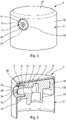
- the dispensing head T comprises two essential constituent parts, namely a head body 1 and a nozzle 2. These two parts can be produced by injection molding of plastic material.
- the head body 1 is preferably made in one piece: it can however be made from several parts assembled together. It is the same for the nozzle 2 which can be produced in a monobloc mono-material manner, or else by overmolding or bi-injection, possibly with a subsequent recovery operation.
- the head body 1 comprises a substantially cylindrical peripheral skirt 10 which is closed off at its upper end by a plate 14.
- the head body 1 also comprises a connection sleeve 15 which here extends concentrically inside the peripheral skirt 10.
- the connecting sleeve 15 extends downwards from the plate 14. It defines internally an inlet well 11 which is open downwards and closed off at its upper end by the plate 12.
- the connection 15 is intended to be mounted on the free end of an actuating rod P5 of the dispensing member P.
- This actuating rod P5 is movable back and forth along the axis Y.
- the rod actuation P5 is hollow so as to define a discharge duct in communication with a chamber of P0 dosing of the P pump or the valve.
- the inlet well 11 extends in the extension of the actuating rod P5 so that the fluid product coming from the metering chamber P0 can flow into the inlet well 11.
- the head body 1 defines also a supply conduit 13 which connects the inlet well 11 to a mounting housing 12, as can be seen in the figure 1 and 3 .
- Axial mounting housing 12 is generally cylindrical in configuration, thereby defining an inner wall which is substantially cylindrical.
- the supply duct 13 opens into the mounting housing 2 in a centered manner. It can also be noted that the internal wall of the mounting housing 12 has hooking profiles allowing better maintenance of the nozzle 2, as will be seen below.
- the head body 1 can be engaged in a covering cap 3 comprising an upper support surface 31 for a finger and a lateral casing 32 forming a lateral opening 33 for the passage of the nozzle 2.
- the nozzle 2 has a substantially conventional overall configuration in the form of a cup which is open at one end and closed at its opposite end by a spray wall 26 at the level of which several holes or spray orifices O are formed.
- the nozzle 2 comprises a nozzle body 20 of substantially cylindrical overall shape which preferably has an axial symmetry of revolution around the axis X, as shown in the figure 1 .
- the nozzle 2 does not need to be oriented angularly before its presentation in front of the inlet of the axial mounting housing 12.
- the nozzle body 20 forms an external mounting wall 21 which is advantageously provided with hooking reliefs capable of cooperating with the hooking profiles of the mounting housing 12.
- the nozzle 2 can be engaged axially without any particular orientation in the axial mounting housing 12, as shown in the figure 1 .
- the nozzle body 20 internally forms a chamber 22 delimited by an internal wall 23 of substantially cylindrical overall configuration, although it forms a frustoconical section 23a and two small cylindrical sections 2b and 23c. On its outer front face, the nozzle body 20 forms a flat annular area 25 in which is formed a guide cone 25.
- the spray wall 26 is integral with the nozzle body 20, advantageously at the level where the small cylindrical section 23c meets the guide cone 25.
- the spray wall 26 is fixed to the nozzle body 20 by any means, such as overmoulding, bi-injection, one-piece mono-material molding, snap-fastening, crimping, expanding, etc.
- the spray wall 26 can be a one-piece single-material part, an assembly of several parts or even a multilayer product, for example laminated. It can be made of metal, plastic, ceramic, glass or a combination thereof. More generally, any material capable of being pierced with small holes or orifices can be used.
- the thickness of the spray wall 26, at the level where the holes O are formed, is of the order of 10 to 100 ⁇ m.
- the number of holes O is of the order of 30 to 500.
- the thickness can be constant, or on the contrary variable.
- the diameter of the spray wall 26, at the level where the holes O are formed is of the order of 0.5 to 5 mm.
- the spray wall 26 can be entirely flat on one or both of its faces, or on the contrary curved, preferably towards the outside.
- the bending of the wall 26 can be carried out after the drilling of the holes O, or on the contrary before their drilling.
- the holes O can have an identical orientation, for example parallel to the axis X, or on the contrary have divergent orientations, in particular when the wall 26 is curved.
- the density of the holes O on the wall 26 can be homogeneous, or on the contrary inhomogeneous, for example increasing or decreasing starting from the center of the wall.
- the holes O are drilled in the spray wall 26 when it is already integral with the nozzle body 20.
- the nozzle body 20 can be used as a manipulation member of the spray wall.
- spraying 26 for its drilling operation which can for example be carried out by laser.
- the spray wall 26 is a very small piece, and therefore difficult to handle.
- the drilling of the holes O with the spray wall 26 premounted on the nozzle body 20 is a process which can be implemented whatever the size of the holes O, that is to say independently of the causes the holes to be of different sizes.
- the holes or spray orifices O form a network of holes comprising two series 27, 28 of holes O of different sizes with the holes O of the same series 27 or 28 having an identical hole size. or unique, taking into account manufacturing tolerances, which do not exceed 10%.
- a spray wall 26 pierced with 100 holes O it is possible to have a first series 28 of 50 holes O having a diameter of 10 ⁇ m and a second series 27 of 50 holes O having a diameter of 20 ⁇ m.
- the first series 28 of 50 holes O will generate a spray of fine droplets whose particle size curve has a peak formed by a relatively narrow Gaussian, then the second series 27 of 50 holes O will generate a spray of larger droplets whose particle size curve also has a peak formed by a relatively narrow Gaussian, which is however shifted and distinct from the first Gaussian of the 28 series.
- a spray is thus obtained with two major droplet sizes corresponding to the two Gaussians of the granulometric curves.
- the distribution between series 27 and 28 can vary from 10 to 90%, and vice versa, with a minimum of five O holes per series.
- the hole size of the 27 series can vary from 15 to 50 ⁇ m, while the hole size of the 28 series can vary from 5 to 20 ⁇ m, with always the size of the 27 series significantly larger, at least by order of 30%, to that of the 28 series.
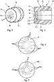
- the spray wall 26 of the dispensing head T of the figures 1 to 5 comprises a first series 27 of ten holes O having a size or a diameter clearly greater than the forty holes O of a second series 28.
- the first series 27 forms a ring which surrounds two other rings forming the series 28
- the overall configuration is concentric.
- This spray wall 26 can be used to spray perfume on the body of a user.
- the diameter of the holes of the first series 27 can be of the order of 15 to 30 ⁇ m and the diameter of the holes of the second series 28 can be of the order of 5 to 15 ⁇ m.
- a spray wall 26b defining two distinct zones, namely an upper zone Zs and a lower zone Zi separated by a horizontal median.
- the holes O of the series 27b of larger diameter occupy the lower zone Zi, while the holes O of the series 28b of smaller diameter occupy the upper zone Zs.
- the two series 27b and 28b present a semi-circular configuration by forming together a complete disc. With this arrangement, the wispy cloud from the O holes of the 28b series quickly disperses in the air and will be immediately perceived by the user's sense of smell, because in general, the target to be perfumed is located below the nose.
- the wetting aspect is preponderant with a channeled olfactory aspect, but nevertheless directed upwards.
- a 26g spray wall is seen with a larger diameter 27g series dispersed within a smaller diameter 28g series.
- the holes O of different sizes are mixed and distributed in a substantially homogeneous manner.
- the number of series of holes, the number of holes per series, the layout of the holes on the spray wall, and the size or diameter of the holes are all parameters that make it possible to determine the number of Gaussians, the peak value of each Gaussian and the structure of the spray. These parameters must be set according to the fluid product to be sprayed and the multiple functions sought: tactile and olfactory for fluid products containing fragrances - penetration at different depths in the respiratory system for a fluid product to be inhaled - precise density gradient and controlled on an application surface.
Landscapes
- Engineering & Computer Science (AREA)
- Mechanical Engineering (AREA)
- Chemical & Material Sciences (AREA)
- Dispersion Chemistry (AREA)
- Containers And Packaging Bodies Having A Special Means To Remove Contents (AREA)
- Nozzles (AREA)
- Perforating, Stamping-Out Or Severing By Means Other Than Cutting (AREA)
- Feeding, Discharge, Calcimining, Fusing, And Gas-Generation Devices (AREA)
Applications Claiming Priority (2)
| Application Number | Priority Date | Filing Date | Title |
|---|---|---|---|
| FR1661845A FR3059573B1 (fr) | 2016-12-02 | 2016-12-02 | Tete de distribution de produit fluide |
| PCT/FR2017/053344 WO2018100321A1 (fr) | 2016-12-02 | 2017-12-01 | Tete de distribution de produit fluide |
Publications (2)
| Publication Number | Publication Date |
|---|---|
| EP3548185A1 EP3548185A1 (fr) | 2019-10-09 |
| EP3548185B1 true EP3548185B1 (fr) | 2022-09-28 |
Family
ID=58401708
Family Applications (1)
| Application Number | Title | Priority Date | Filing Date |
|---|---|---|---|
| EP17821972.1A Active EP3548185B1 (fr) | 2016-12-02 | 2017-12-01 | Distributeur de produit fluide |
Country Status (8)
| Country | Link |
|---|---|
| US (2) | US11633747B2 (enExample) |
| EP (1) | EP3548185B1 (enExample) |
| JP (1) | JP7094286B2 (enExample) |
| CN (5) | CN110035830A (enExample) |
| BR (4) | BR112019010499B1 (enExample) |
| ES (3) | ES2929990T3 (enExample) |
| FR (5) | FR3059573B1 (enExample) |
| WO (1) | WO2018100321A1 (enExample) |
Families Citing this family (14)
| Publication number | Priority date | Publication date | Assignee | Title |
|---|---|---|---|---|
| EP3569318A1 (en) | 2018-05-16 | 2019-11-20 | Medspray B.V. | Spray device for generating a micro-jet spray |
| DE102019109081B4 (de) * | 2018-07-03 | 2020-06-04 | MO GmbH & Co. KG | Aerosol-Dispersionseinrichtung |
| DE102019109079B4 (de) * | 2018-07-03 | 2020-06-04 | MO GmbH & Co. KG | Aerosol-Dispersionseinrichtung |
| DE102019109080A1 (de) * | 2018-07-03 | 2020-01-09 | MO GmbH & Co. KG | Aerosol-Dispersionseinrichtung |
| US10940493B2 (en) * | 2018-07-26 | 2021-03-09 | S. C. Johnson & Son, Inc. | Actuator and nozzle insert for dispensing systems |
| FR3095968B1 (fr) * | 2019-05-14 | 2021-10-01 | Aptar France Sas | Dispositif de distribution de produit fluide |
| FR3096089B1 (fr) | 2019-05-14 | 2022-08-05 | Aptar France Sas | Procédé d'assemblage d'une pompe à précompression haute pression |
| FR3096090B1 (fr) | 2019-05-14 | 2022-10-28 | Aptar France Sas | Pompe à précompression haute pression |
| WO2021099696A1 (fr) * | 2019-11-22 | 2021-05-27 | Aptar France Sas | Procede de fabrication d'une paroi de distribution |
| JP2021122786A (ja) * | 2020-02-05 | 2021-08-30 | 三菱ケミカル・クリンスイ株式会社 | 浄水器 |
| KR102690910B1 (ko) | 2020-09-17 | 2024-08-02 | 주식회사 엘지화학 | 스파저 및 이를 포함하는 반응기 |
| KR20230145574A (ko) * | 2021-01-17 | 2023-10-17 | 에스.씨. 존슨 앤 선 인코포레이티드 | 에어로졸 스프레이, 에어로졸 스프레이 생성 방법,및 에어로졸 디스펜싱 시스템 |
| CN112676450B (zh) * | 2021-01-27 | 2025-05-02 | 博瑞孚曼机械科技(苏州)有限公司 | 一种高强钢辊压成型圆弧位置在线冲孔装置 |
| CN115837427A (zh) * | 2022-11-12 | 2023-03-24 | 嘉兴和新精冲科技有限公司 | 一种外形内孔全斜面精冲密封阀片的生产工艺 |
Citations (2)
| Publication number | Priority date | Publication date | Assignee | Title |
|---|---|---|---|---|
| WO2016036228A1 (ko) * | 2014-09-05 | 2016-03-10 | 강성일 | 가압이 편리한 펌프를 구비한 파운데이션 용기 |
| WO2016099158A1 (ko) * | 2014-12-19 | 2016-06-23 | 강성일 | 세라믹 재질의 배출판을 구비한 콤팩트 용기 |
Family Cites Families (64)
| Publication number | Priority date | Publication date | Assignee | Title |
|---|---|---|---|---|
| US479979A (en) * | 1891-01-05 | 1892-08-02 | Sprinkling apparatus | |
| US2428292A (en) * | 1944-11-16 | 1947-09-30 | Chester V Queen | Spraying device for coating the inside of pipe |
| US2647800A (en) * | 1949-03-31 | 1953-08-04 | Thompson W Burnam | Fire extinguishing nozzle and distributor head |
| US3731517A (en) * | 1968-12-30 | 1973-05-08 | Patent And Devel Of North Caro | Method of fabricating a fluid dispersion nozzle |
| US3606618A (en) * | 1970-03-31 | 1971-09-21 | Robert D Veech | Portable shower bath |
| US3724403A (en) * | 1971-11-12 | 1973-04-03 | Northern Natural Gas Co | Forced draft furnace system |
| FR2264598B2 (enExample) * | 1974-03-20 | 1979-04-13 | Fives Cail Babcock | |
| US4013227A (en) * | 1975-08-19 | 1977-03-22 | Herrera John T | Welding torch tip and method |
| JPS59122149U (ja) * | 1983-02-08 | 1984-08-17 | 北林 誠一 | エアゾル消火器用噴射頭 |
| US4490411A (en) * | 1983-03-14 | 1984-12-25 | Darryl Feder | Apparatus for and method of metalizing internal surfaces of metal bodies such as tubes and pipes |
| JPS59206064A (ja) * | 1983-05-10 | 1984-11-21 | Asahi Okuma Ind Co Ltd | エアレス塗装用ノズル |
| US4668852A (en) * | 1985-02-05 | 1987-05-26 | The Perkin-Elmer Corporation | Arc spray system |
| JPH043639Y2 (enExample) * | 1986-04-22 | 1992-02-04 | ||
| US5004158A (en) * | 1989-08-21 | 1991-04-02 | Stephen Halem | Fluid dispensing and mixing device |
| US5080286A (en) * | 1990-05-31 | 1992-01-14 | The United States Of America As Represented By The Administrator Of The National Aeronautics And Space Administration | Stable stream producing flexible orifice independent of fluid pressure |
| US5080056A (en) * | 1991-05-17 | 1992-01-14 | General Motors Corporation | Thermally sprayed aluminum-bronze coatings on aluminum engine bores |
| US5201468A (en) * | 1991-07-31 | 1993-04-13 | Kohler Co. | Pulsating fluid spray apparatus |
| FR2691383B1 (fr) * | 1992-05-21 | 1994-08-19 | Oreal | Bouton-poussoir destiné à être monté sur une valve ou une pompe équipant un distributeur, et distributeur comportant un tel bouton-poussoir. |
| US5294054A (en) * | 1992-05-22 | 1994-03-15 | Benedict Engineering Company, Inc. | Adjustable showerhead assemblies |
| US5540200A (en) * | 1993-12-28 | 1996-07-30 | Nissan Motor Co., Ltd. | Fuel injection valve |
| US5476225A (en) * | 1994-06-24 | 1995-12-19 | Jing Mei Industrial Limited | Multi spray pattern shower head |
| US5639025A (en) * | 1995-07-07 | 1997-06-17 | The Procter & Gamble Company | High Viscosity pump sprayer utilizing fan spray nozzle |
| WO1997004697A2 (es) * | 1995-07-31 | 1997-02-13 | Aqua-Save, S.A. De C.V. | Regadera para baño, de alta eficiencia a baja presion |
| JPH1172067A (ja) * | 1997-06-24 | 1999-03-16 | Toyota Motor Corp | 内燃機関の燃料噴射弁 |
| JP3343672B2 (ja) * | 1997-08-18 | 2002-11-11 | 愛三工業株式会社 | 燃料噴射弁 |
| JP2000325251A (ja) * | 1999-03-18 | 2000-11-28 | Toto Ltd | シャワーヘッド |
| US6158674A (en) * | 1999-04-28 | 2000-12-12 | Humphreys; Ronald O. | Liquid dispenser with multiple nozzles |
| JP2001286790A (ja) * | 2000-04-07 | 2001-10-16 | Nissan Motor Co Ltd | 液体噴射装置 |
| JP2004501709A (ja) * | 2000-07-05 | 2004-01-22 | ユニリーバー・ナームローゼ・ベンノートシヤープ | スプレーヘッド |
| JP2002186882A (ja) * | 2000-12-19 | 2002-07-02 | Kyowa Kogyo Kk | ノズル組立体 |
| DE10122350B4 (de) | 2001-05-09 | 2006-09-07 | Robert Bosch Gmbh | Brennstoffeinspritzsystem |
| JP3640209B2 (ja) * | 2002-06-28 | 2005-04-20 | 識雄 浦 | 噴霧ノズル |
| US20040155125A1 (en) * | 2003-02-11 | 2004-08-12 | Kramer Martin S. | High pressure fluid jet nozzles and methods of making |
| JPWO2004085835A1 (ja) * | 2003-03-27 | 2006-06-29 | 日本碍子株式会社 | 液体噴射装置及びその製造方法 |
| US7124963B2 (en) * | 2004-11-05 | 2006-10-24 | Visteon Global Technologies, Inc. | Low pressure fuel injector nozzle |
| DE202004019745U1 (de) * | 2004-12-22 | 2005-02-24 | Strahmann, Lüder, Dipl.-Kfm. | Verwirbelungsgerät zur Verbesserung von Flüssigkeiten |
| DE102005010173B4 (de) * | 2005-03-05 | 2006-11-16 | Aero Pump GmbH, Zerstäuberpumpen | Austrittshaube für ein Sprühgerät zum Versprühen einer hochviskosen Flüssigkeit |
| US20070145164A1 (en) * | 2005-12-22 | 2007-06-28 | Nordson Corporation | Jetting dispenser with multiple jetting nozzle outlets |
| FR2903329B3 (fr) * | 2006-07-10 | 2008-10-03 | Rexam Dispensing Systems Sas | Buse de pulverisation, dispositif de pulverisation et utilisation de ce dispositif. |
| FR2903328B1 (fr) | 2006-07-10 | 2008-12-05 | Rexam Dispensing Systems Sas | Buse de pulverisation, dispositif de pulverisation et utilisation de ce dispositif. |
| CN200982635Y (zh) * | 2006-12-04 | 2007-11-28 | 郑州引航实业有限公司 | 一种燃气焊炬喷嘴 |
| JP4305962B2 (ja) * | 2007-01-12 | 2009-07-29 | 株式会社デンソー | 噴孔部材およびそれを用いた燃料噴射弁 |
| DE102007051487A1 (de) * | 2007-10-27 | 2009-04-30 | Thinxxs Microtechnology Ag | Düsen-, Filter- oder/und Positionierelement |
| CN101428256B (zh) * | 2007-11-07 | 2011-09-14 | 北京北方微电子基地设备工艺研究中心有限责任公司 | 一种喷嘴装置及应用该喷嘴装置的半导体处理设备 |
| GB0800709D0 (en) * | 2008-01-16 | 2008-02-20 | Dunne Stephen T | Double jet impinging nozzle |
| TWI338592B (en) * | 2008-03-25 | 2011-03-11 | Ind Tech Res Inst | Nozzle plate of a spray apparatus and fabrication method thereof |
| CN201316612Y (zh) * | 2008-09-12 | 2009-09-30 | 周建业 | 一种喷头 |
| GB2466631A (en) * | 2008-10-21 | 2010-07-07 | Philip Alan Durrant | A spray device for atomising fluids having at least three nozzles with a restriction |
| FR2941158B1 (fr) * | 2009-01-16 | 2014-07-18 | Rieter Perfojet | Dispositif de projection de jets d'eau par une plaquette perforee courbee |
| WO2010089822A1 (ja) * | 2009-02-09 | 2010-08-12 | 株式会社村田製作所 | 霧化部材及びそれを備える霧化器 |
| JP5464511B2 (ja) * | 2009-05-14 | 2014-04-09 | 独立行政法人物質・材料研究機構 | 液体噴射用オリフィスプレートの製造方法 |
| EP2390010B1 (en) * | 2010-05-28 | 2014-03-12 | EP Systems SA | Nozzle body for an ultrasonic liquid droplet spray device |
| CN102019236B (zh) * | 2011-01-04 | 2013-05-01 | 北京航空航天大学 | 用于复杂流体雾化的自激振荡射流撞击式喷嘴 |
| WO2013064299A1 (en) * | 2011-10-31 | 2013-05-10 | Unilever N.V. | Nozzle assembly |
| US20150211462A1 (en) * | 2012-08-01 | 2015-07-30 | 3M Innovative Properties Company | Fuel injector nozzles with at least one multiple inlet port and/or multiple outlet port |
| WO2014080265A1 (en) * | 2012-11-20 | 2014-05-30 | Nostrum Energy Pte. Ltd. | Liquid injector atomizer with colliding jets |
| CN104582859B (zh) | 2013-03-25 | 2018-02-27 | 株式会社漫丹 | 气溶胶制品和气溶胶制品的用途 |
| JP6243708B2 (ja) | 2013-11-19 | 2017-12-06 | 株式会社マンダム | エアゾール製品 |
| JP2014205114A (ja) * | 2013-04-12 | 2014-10-30 | 住友化学株式会社 | 超音波霧化装置、および薬剤 |
| US20150211728A1 (en) * | 2014-01-27 | 2015-07-30 | Eli Zhadanov | Showerhead |
| CN103977919A (zh) * | 2014-05-30 | 2014-08-13 | 许玉方 | 多孔喷嘴 |
| CA2955807C (en) * | 2014-08-28 | 2018-11-13 | Nebia Inc. | Immersive showerhead |
| CN104874494B (zh) * | 2015-05-20 | 2017-10-24 | 厦门建霖工业有限公司 | 双稳附壁式水流芯及其出水装置和出水方法 |
| CN206184618U (zh) * | 2016-11-11 | 2017-05-24 | 环保桥(湖南)生态环境修复有限公司 | 一种针对浆液状土壤污染修复剂的撒施喷管设备 |
-
2016
- 2016-12-02 FR FR1661845A patent/FR3059573B1/fr active Active
-
2017
- 2017-12-01 EP EP17821972.1A patent/EP3548185B1/fr active Active
- 2017-12-01 JP JP2019529632A patent/JP7094286B2/ja not_active Expired - Fee Related
- 2017-12-01 BR BR112019010499-2A patent/BR112019010499B1/pt active IP Right Grant
- 2017-12-01 CN CN201780074176.3A patent/CN110035830A/zh active Pending
- 2017-12-01 ES ES17821972T patent/ES2929990T3/es active Active
- 2017-12-01 US US16/465,272 patent/US11633747B2/en active Active
- 2017-12-01 WO PCT/FR2017/053344 patent/WO2018100321A1/fr not_active Ceased
-
2018
- 2018-03-09 FR FR1852083A patent/FR3074431B1/fr active Active
- 2018-03-09 FR FR1852079A patent/FR3074430B1/fr active Active
- 2018-03-09 FR FR1852072A patent/FR3074429B1/fr active Active
- 2018-03-09 FR FR1852087A patent/FR3074432B1/fr active Active
- 2018-11-30 BR BR112020009541-9A patent/BR112020009541B1/pt active IP Right Grant
- 2018-11-30 CN CN201880077745.4A patent/CN111432938B/zh active Active
- 2018-11-30 BR BR112020009539-7A patent/BR112020009539B1/pt active IP Right Grant
- 2018-11-30 ES ES18833264T patent/ES2953811T3/es active Active
- 2018-11-30 CN CN201880077756.2A patent/CN111432939B/zh active Active
- 2018-11-30 CN CN202210510181.7A patent/CN114904961A/zh active Pending
- 2018-11-30 CN CN201880077414.0A patent/CN111655381A/zh active Pending
- 2018-11-30 BR BR112020009538-9A patent/BR112020009538B1/pt active IP Right Grant
- 2018-11-30 US US16/764,232 patent/US12076733B2/en active Active
- 2018-11-30 ES ES18855177T patent/ES3040196T3/es active Active
Patent Citations (2)
| Publication number | Priority date | Publication date | Assignee | Title |
|---|---|---|---|---|
| WO2016036228A1 (ko) * | 2014-09-05 | 2016-03-10 | 강성일 | 가압이 편리한 펌프를 구비한 파운데이션 용기 |
| WO2016099158A1 (ko) * | 2014-12-19 | 2016-06-23 | 강성일 | 세라믹 재질의 배출판을 구비한 콤팩트 용기 |
Also Published As
Similar Documents
| Publication | Publication Date | Title |
|---|---|---|
| EP3548185B1 (fr) | Distributeur de produit fluide | |
| EP1878507B2 (fr) | Dispositif de pulvérisation et utilisation de ce dispositif | |
| EP2496361B2 (fr) | Bouton poussoir pour un système de distribution d'un produit sous pression | |
| CN104144751A (zh) | 配给头 | |
| FR2903328A1 (fr) | Buse de pulverisation, dispositif de pulverisation et utilisation de ce dispositif. | |
| EP3717137B1 (fr) | Tête de distribution de produit fluide | |
| EP2606980B1 (fr) | Bouton poussoir pour un système de distribution d'un produit sous pression | |
| EP3717135B1 (fr) | Tête de distribution de produit fluide et procédé correspondant | |
| WO2023111470A1 (fr) | Tete de pulverisation | |
| EP3717134B1 (fr) | Tête de distribution de produit fluide | |
| EP3615224B1 (fr) | Tete de distribution de produit fluide. | |
| EP2353726B1 (fr) | Bouton poussoir pour un système de distribution d'un produit sous pression | |
| WO2021099696A1 (fr) | Procede de fabrication d'une paroi de distribution | |
| FR3065653A1 (fr) | Tete de distribution de produit fluide. | |
| WO2023152446A1 (fr) | Dispositif de distribution de produit fluide | |
| WO2018041594A1 (fr) | Tête de distribution d'un fluide sous pression et bombe aérosol ou pompe à actionnement manuel comprenant une telle tête de distribution | |
| FR2933883A1 (fr) | Buse de pulverisation de produit fluide et poussoir integrant une telle buse |
Legal Events
| Date | Code | Title | Description |
|---|---|---|---|
| STAA | Information on the status of an ep patent application or granted ep patent |
Free format text: STATUS: UNKNOWN |
|
| STAA | Information on the status of an ep patent application or granted ep patent |
Free format text: STATUS: THE INTERNATIONAL PUBLICATION HAS BEEN MADE |
|
| PUAI | Public reference made under article 153(3) epc to a published international application that has entered the european phase |
Free format text: ORIGINAL CODE: 0009012 |
|
| STAA | Information on the status of an ep patent application or granted ep patent |
Free format text: STATUS: REQUEST FOR EXAMINATION WAS MADE |
|
| 17P | Request for examination filed |
Effective date: 20190628 |
|
| AK | Designated contracting states |
Kind code of ref document: A1 Designated state(s): AL AT BE BG CH CY CZ DE DK EE ES FI FR GB GR HR HU IE IS IT LI LT LU LV MC MK MT NL NO PL PT RO RS SE SI SK SM TR |
|
| AX | Request for extension of the european patent |
Extension state: BA ME |
|
| DAV | Request for validation of the european patent (deleted) | ||
| DAX | Request for extension of the european patent (deleted) | ||
| STAA | Information on the status of an ep patent application or granted ep patent |
Free format text: STATUS: EXAMINATION IS IN PROGRESS |
|
| 17Q | First examination report despatched |
Effective date: 20200805 |
|
| REG | Reference to a national code |
Ref country code: DE Ref legal event code: R079 Ref document number: 602017062211 Country of ref document: DE Free format text: PREVIOUS MAIN CLASS: B05B0001000000 Ipc: B05B0001140000 |
|
| GRAP | Despatch of communication of intention to grant a patent |
Free format text: ORIGINAL CODE: EPIDOSNIGR1 |
|
| RIC1 | Information provided on ipc code assigned before grant |
Ipc: B65D 83/14 20060101ALI20220317BHEP Ipc: B65D 83/28 20060101ALI20220317BHEP Ipc: B05B 11/00 20060101ALI20220317BHEP Ipc: B05B 7/08 20060101ALI20220317BHEP Ipc: B05B 1/18 20060101ALI20220317BHEP Ipc: B05B 1/14 20060101AFI20220317BHEP |
|
| STAA | Information on the status of an ep patent application or granted ep patent |
Free format text: STATUS: GRANT OF PATENT IS INTENDED |
|
| INTG | Intention to grant announced |
Effective date: 20220421 |
|
| GRAS | Grant fee paid |
Free format text: ORIGINAL CODE: EPIDOSNIGR3 |
|
| GRAA | (expected) grant |
Free format text: ORIGINAL CODE: 0009210 |
|
| STAA | Information on the status of an ep patent application or granted ep patent |
Free format text: STATUS: THE PATENT HAS BEEN GRANTED |
|
| AK | Designated contracting states |
Kind code of ref document: B1 Designated state(s): AL AT BE BG CH CY CZ DE DK EE ES FI FR GB GR HR HU IE IS IT LI LT LU LV MC MK MT NL NO PL PT RO RS SE SI SK SM TR |
|
| REG | Reference to a national code |
Ref country code: GB Ref legal event code: FG4D Free format text: NOT ENGLISH |
|
| REG | Reference to a national code |
Ref country code: CH Ref legal event code: EP |
|
| REG | Reference to a national code |
Ref country code: AT Ref legal event code: REF Ref document number: 1520898 Country of ref document: AT Kind code of ref document: T Effective date: 20221015 |
|
| REG | Reference to a national code |
Ref country code: DE Ref legal event code: R096 Ref document number: 602017062211 Country of ref document: DE |
|
| REG | Reference to a national code |
Ref country code: IE Ref legal event code: FG4D Free format text: LANGUAGE OF EP DOCUMENT: FRENCH |
|
| REG | Reference to a national code |
Ref country code: ES Ref legal event code: FG2A Ref document number: 2929990 Country of ref document: ES Kind code of ref document: T3 Effective date: 20221205 |
|
| REG | Reference to a national code |
Ref country code: LT Ref legal event code: MG9D |
|
| PG25 | Lapsed in a contracting state [announced via postgrant information from national office to epo] |
Ref country code: SE Free format text: LAPSE BECAUSE OF FAILURE TO SUBMIT A TRANSLATION OF THE DESCRIPTION OR TO PAY THE FEE WITHIN THE PRESCRIBED TIME-LIMIT Effective date: 20220928 Ref country code: RS Free format text: LAPSE BECAUSE OF FAILURE TO SUBMIT A TRANSLATION OF THE DESCRIPTION OR TO PAY THE FEE WITHIN THE PRESCRIBED TIME-LIMIT Effective date: 20220928 Ref country code: NO Free format text: LAPSE BECAUSE OF FAILURE TO SUBMIT A TRANSLATION OF THE DESCRIPTION OR TO PAY THE FEE WITHIN THE PRESCRIBED TIME-LIMIT Effective date: 20221228 Ref country code: LV Free format text: LAPSE BECAUSE OF FAILURE TO SUBMIT A TRANSLATION OF THE DESCRIPTION OR TO PAY THE FEE WITHIN THE PRESCRIBED TIME-LIMIT Effective date: 20220928 Ref country code: LT Free format text: LAPSE BECAUSE OF FAILURE TO SUBMIT A TRANSLATION OF THE DESCRIPTION OR TO PAY THE FEE WITHIN THE PRESCRIBED TIME-LIMIT Effective date: 20220928 Ref country code: FI Free format text: LAPSE BECAUSE OF FAILURE TO SUBMIT A TRANSLATION OF THE DESCRIPTION OR TO PAY THE FEE WITHIN THE PRESCRIBED TIME-LIMIT Effective date: 20220928 |
|
| REG | Reference to a national code |
Ref country code: NL Ref legal event code: MP Effective date: 20220928 |
|
| REG | Reference to a national code |
Ref country code: AT Ref legal event code: MK05 Ref document number: 1520898 Country of ref document: AT Kind code of ref document: T Effective date: 20220928 |
|
| PG25 | Lapsed in a contracting state [announced via postgrant information from national office to epo] |
Ref country code: HR Free format text: LAPSE BECAUSE OF FAILURE TO SUBMIT A TRANSLATION OF THE DESCRIPTION OR TO PAY THE FEE WITHIN THE PRESCRIBED TIME-LIMIT Effective date: 20220928 Ref country code: GR Free format text: LAPSE BECAUSE OF FAILURE TO SUBMIT A TRANSLATION OF THE DESCRIPTION OR TO PAY THE FEE WITHIN THE PRESCRIBED TIME-LIMIT Effective date: 20221229 |
|
| PG25 | Lapsed in a contracting state [announced via postgrant information from national office to epo] |
Ref country code: SM Free format text: LAPSE BECAUSE OF FAILURE TO SUBMIT A TRANSLATION OF THE DESCRIPTION OR TO PAY THE FEE WITHIN THE PRESCRIBED TIME-LIMIT Effective date: 20220928 Ref country code: RO Free format text: LAPSE BECAUSE OF FAILURE TO SUBMIT A TRANSLATION OF THE DESCRIPTION OR TO PAY THE FEE WITHIN THE PRESCRIBED TIME-LIMIT Effective date: 20220928 Ref country code: PT Free format text: LAPSE BECAUSE OF FAILURE TO SUBMIT A TRANSLATION OF THE DESCRIPTION OR TO PAY THE FEE WITHIN THE PRESCRIBED TIME-LIMIT Effective date: 20230130 Ref country code: CZ Free format text: LAPSE BECAUSE OF FAILURE TO SUBMIT A TRANSLATION OF THE DESCRIPTION OR TO PAY THE FEE WITHIN THE PRESCRIBED TIME-LIMIT Effective date: 20220928 Ref country code: AT Free format text: LAPSE BECAUSE OF FAILURE TO SUBMIT A TRANSLATION OF THE DESCRIPTION OR TO PAY THE FEE WITHIN THE PRESCRIBED TIME-LIMIT Effective date: 20220928 |
|
| PG25 | Lapsed in a contracting state [announced via postgrant information from national office to epo] |
Ref country code: SK Free format text: LAPSE BECAUSE OF FAILURE TO SUBMIT A TRANSLATION OF THE DESCRIPTION OR TO PAY THE FEE WITHIN THE PRESCRIBED TIME-LIMIT Effective date: 20220928 Ref country code: PL Free format text: LAPSE BECAUSE OF FAILURE TO SUBMIT A TRANSLATION OF THE DESCRIPTION OR TO PAY THE FEE WITHIN THE PRESCRIBED TIME-LIMIT Effective date: 20220928 Ref country code: IS Free format text: LAPSE BECAUSE OF FAILURE TO SUBMIT A TRANSLATION OF THE DESCRIPTION OR TO PAY THE FEE WITHIN THE PRESCRIBED TIME-LIMIT Effective date: 20230128 Ref country code: EE Free format text: LAPSE BECAUSE OF FAILURE TO SUBMIT A TRANSLATION OF THE DESCRIPTION OR TO PAY THE FEE WITHIN THE PRESCRIBED TIME-LIMIT Effective date: 20220928 |
|
| REG | Reference to a national code |
Ref country code: DE Ref legal event code: R097 Ref document number: 602017062211 Country of ref document: DE |
|
| PG25 | Lapsed in a contracting state [announced via postgrant information from national office to epo] |
Ref country code: NL Free format text: LAPSE BECAUSE OF FAILURE TO SUBMIT A TRANSLATION OF THE DESCRIPTION OR TO PAY THE FEE WITHIN THE PRESCRIBED TIME-LIMIT Effective date: 20220928 Ref country code: AL Free format text: LAPSE BECAUSE OF FAILURE TO SUBMIT A TRANSLATION OF THE DESCRIPTION OR TO PAY THE FEE WITHIN THE PRESCRIBED TIME-LIMIT Effective date: 20220928 |
|
| REG | Reference to a national code |
Ref country code: DE Ref legal event code: R119 Ref document number: 602017062211 Country of ref document: DE |
|
| P01 | Opt-out of the competence of the unified patent court (upc) registered |
Effective date: 20230526 |
|
| PG25 | Lapsed in a contracting state [announced via postgrant information from national office to epo] |
Ref country code: DK Free format text: LAPSE BECAUSE OF FAILURE TO SUBMIT A TRANSLATION OF THE DESCRIPTION OR TO PAY THE FEE WITHIN THE PRESCRIBED TIME-LIMIT Effective date: 20220928 |
|
| REG | Reference to a national code |
Ref country code: CH Ref legal event code: PL |
|
| PLBE | No opposition filed within time limit |
Free format text: ORIGINAL CODE: 0009261 |
|
| STAA | Information on the status of an ep patent application or granted ep patent |
Free format text: STATUS: NO OPPOSITION FILED WITHIN TIME LIMIT |
|
| GBPC | Gb: european patent ceased through non-payment of renewal fee |
Effective date: 20221228 |
|
| REG | Reference to a national code |
Ref country code: BE Ref legal event code: MM Effective date: 20221231 |
|
| PG25 | Lapsed in a contracting state [announced via postgrant information from national office to epo] |
Ref country code: LU Free format text: LAPSE BECAUSE OF NON-PAYMENT OF DUE FEES Effective date: 20221201 |
|
| 26N | No opposition filed |
Effective date: 20230629 |
|
| PG25 | Lapsed in a contracting state [announced via postgrant information from national office to epo] |
Ref country code: LI Free format text: LAPSE BECAUSE OF NON-PAYMENT OF DUE FEES Effective date: 20221231 Ref country code: IE Free format text: LAPSE BECAUSE OF NON-PAYMENT OF DUE FEES Effective date: 20221201 Ref country code: GB Free format text: LAPSE BECAUSE OF NON-PAYMENT OF DUE FEES Effective date: 20221228 Ref country code: DE Free format text: LAPSE BECAUSE OF NON-PAYMENT OF DUE FEES Effective date: 20230701 Ref country code: CH Free format text: LAPSE BECAUSE OF NON-PAYMENT OF DUE FEES Effective date: 20221231 |
|
| PG25 | Lapsed in a contracting state [announced via postgrant information from national office to epo] |
Ref country code: SI Free format text: LAPSE BECAUSE OF FAILURE TO SUBMIT A TRANSLATION OF THE DESCRIPTION OR TO PAY THE FEE WITHIN THE PRESCRIBED TIME-LIMIT Effective date: 20220928 Ref country code: BE Free format text: LAPSE BECAUSE OF NON-PAYMENT OF DUE FEES Effective date: 20221231 |
|
| PG25 | Lapsed in a contracting state [announced via postgrant information from national office to epo] |
Ref country code: HU Free format text: LAPSE BECAUSE OF FAILURE TO SUBMIT A TRANSLATION OF THE DESCRIPTION OR TO PAY THE FEE WITHIN THE PRESCRIBED TIME-LIMIT; INVALID AB INITIO Effective date: 20171201 |
|
| PG25 | Lapsed in a contracting state [announced via postgrant information from national office to epo] |
Ref country code: CY Free format text: LAPSE BECAUSE OF FAILURE TO SUBMIT A TRANSLATION OF THE DESCRIPTION OR TO PAY THE FEE WITHIN THE PRESCRIBED TIME-LIMIT Effective date: 20220928 |
|
| PG25 | Lapsed in a contracting state [announced via postgrant information from national office to epo] |
Ref country code: MK Free format text: LAPSE BECAUSE OF FAILURE TO SUBMIT A TRANSLATION OF THE DESCRIPTION OR TO PAY THE FEE WITHIN THE PRESCRIBED TIME-LIMIT Effective date: 20220928 Ref country code: IT Free format text: LAPSE BECAUSE OF FAILURE TO SUBMIT A TRANSLATION OF THE DESCRIPTION OR TO PAY THE FEE WITHIN THE PRESCRIBED TIME-LIMIT Effective date: 20220928 |
|
| PG25 | Lapsed in a contracting state [announced via postgrant information from national office to epo] |
Ref country code: MC Free format text: LAPSE BECAUSE OF FAILURE TO SUBMIT A TRANSLATION OF THE DESCRIPTION OR TO PAY THE FEE WITHIN THE PRESCRIBED TIME-LIMIT Effective date: 20220928 |
|
| PG25 | Lapsed in a contracting state [announced via postgrant information from national office to epo] |
Ref country code: MC Free format text: LAPSE BECAUSE OF FAILURE TO SUBMIT A TRANSLATION OF THE DESCRIPTION OR TO PAY THE FEE WITHIN THE PRESCRIBED TIME-LIMIT Effective date: 20220928 |
|
| PG25 | Lapsed in a contracting state [announced via postgrant information from national office to epo] |
Ref country code: BG Free format text: LAPSE BECAUSE OF FAILURE TO SUBMIT A TRANSLATION OF THE DESCRIPTION OR TO PAY THE FEE WITHIN THE PRESCRIBED TIME-LIMIT Effective date: 20220928 |
|
| PG25 | Lapsed in a contracting state [announced via postgrant information from national office to epo] |
Ref country code: MT Free format text: LAPSE BECAUSE OF FAILURE TO SUBMIT A TRANSLATION OF THE DESCRIPTION OR TO PAY THE FEE WITHIN THE PRESCRIBED TIME-LIMIT Effective date: 20220928 |
|
| PG25 | Lapsed in a contracting state [announced via postgrant information from national office to epo] |
Ref country code: TR Free format text: LAPSE BECAUSE OF FAILURE TO SUBMIT A TRANSLATION OF THE DESCRIPTION OR TO PAY THE FEE WITHIN THE PRESCRIBED TIME-LIMIT Effective date: 20220928 |
|
| PGFP | Annual fee paid to national office [announced via postgrant information from national office to epo] |
Ref country code: FR Payment date: 20251231 Year of fee payment: 9 |
|
| PGFP | Annual fee paid to national office [announced via postgrant information from national office to epo] |
Ref country code: ES Payment date: 20260112 Year of fee payment: 9 |