EP3546294A1 - Klapptreppe - Google Patents
Klapptreppe Download PDFInfo
- Publication number
- EP3546294A1 EP3546294A1 EP19164737.9A EP19164737A EP3546294A1 EP 3546294 A1 EP3546294 A1 EP 3546294A1 EP 19164737 A EP19164737 A EP 19164737A EP 3546294 A1 EP3546294 A1 EP 3546294A1
- Authority
- EP
- European Patent Office
- Prior art keywords
- folding staircase
- wall
- fastening element
- folding
- support
- Prior art date
- Legal status (The legal status is an assumption and is not a legal conclusion. Google has not performed a legal analysis and makes no representation as to the accuracy of the status listed.)
- Granted
Links
Images


Classifications
-
- B—PERFORMING OPERATIONS; TRANSPORTING
- B60—VEHICLES IN GENERAL
- B60R—VEHICLES, VEHICLE FITTINGS, OR VEHICLE PARTS, NOT OTHERWISE PROVIDED FOR
- B60R3/00—Arrangements of steps or ladders facilitating access to or on the vehicle, e.g. running-boards
- B60R3/02—Retractable steps or ladders, e.g. movable under shock
Definitions
- the invention relates to a folding staircase. Furthermore, the invention relates to a motorhome having a folding staircase according to the invention.
- a climbing aid In motorhomes, such as mobile homes, caravans or horse transporters with a living area, it is customary to provide space for reasons of sleep at a certain height, for example, above the cab in the case of a mobile home or above the stabling unit in the case of a horse transporter.
- a climbing aid In order to achieve such sleeping arrangements, a climbing aid must be provided due to the amount of sleeping accommodation. It is known to provide a climbing aid in the form of a staircase, it being common that the staircase is attached only when used, for example, with hooks on the bedding. If the lifts are not needed, for example, during the day, they must be stowed in another part of the motorhome, so as not to restrict the freedom of movement of the users of the motorhome.
- the stowage of the climbing aid which is usually very stable and thus designed heavy, costs storage space, which thus can not be used elsewhere in the already cramped conditions of a motorhome. There is therefore a need to provide a climbing aid which, when not in use, requires the least possible space and thus storage space.
- the holding system is adapted to be mounted on a wall, wherein in the unfolded state, the top of the at least one step is aligned horizontally to the wall to form a climbing aid and wherein in the closed state, the underside of the at least one Stairway is aligned parallel to the wall, the stairs can, when it is not needed, remain on the wall, the staircase in this state requires no additional storage space.
- the folding staircase is adapted to be mounted on the wall, in particular to be embedded in the wall, that in the closed state, the underside of the at least one step is aligned with the wall.
- the underside of the at least one step with the wall forms a surface, so the folding staircase disappears completely in the wall.
- a certain recess in the wall is provided for attaching the folding staircase, in which the folding staircase can be mounted. With such an attachment, a certain design-related deviation from the desired alignment between the wall and the underside of the at least one step must be tolerated. Such a deviation is preferably in a range of less than 5 cm.
- the retention system further comprises a fastener adapted to attach the folding staircase to the wall and a support member, the support member adapted to support the at least one step in the unfolded state.
- the fastener is adapted to the folding stairs permanently, that is, without the possibility for the user to remove the folding staircase from the wall to install on the wall.
- the fastener is preferably adapted to be recessed into the wall to attach the folding staircase to the wall. This means “let into the wall” that in the wall recesses be provided, in which the fastener and the folding staircase can be introduced.
- the support element is preferably arranged movably on the fastening element.
- the at least one step is attached to the attachment element by means of a first pivot and by means of a second pivot to the support element.
- the support element is mounted by means of a rotary push joint on the fastening element and the rotary push joint is adapted to allow a pushing movement of the support element vertically along the fastening element.
- the fastening element has a rail portion, wherein the support element is attached by means of the rotary push joint on the rail portion of the fastener and the support member is adapted to move by means of the rotary push joint at a transition between the folded and the unfolded state along the rail portion ,
- the rail portion of the fastener is adapted to fully receive in the folded state, the support member to allow aligning the underside of the at least one step on the wall.
- the support member further comprises a first portion and a second portion, the first portion being movably disposed on the fastener and the at least one step movably disposed on the second portion, the first portion being connected to the second portion via a hinge is and in an unfolded state, the first portion forms an angle with the wall and the second portion is vertically parallel to the wall.
- the angle which the first section forms with the wall is greater than 0 ° and less than 90 °. In a particularly preferred embodiment, the angle is 30 °.
- the first portion and the second portion are each formed as a pipe or rod with a rectangular cross-section.
- the fastening element has a first magnet and the support element has a second magnet, the magnets being concealed arranged and arranged such that in the closed state the magnets hold the folding staircase in the closed state.
- the distance between the top and bottom of the at least one step in the unfolded state decreases as the distance from the wall increases. This has the advantage that the steps in the folded state do not touch the part of the wall located behind the steps or part of the rear wall of the recess in the wall. During a trip with a motorhome in which the folding staircase is installed, so the steps can not damage or wear the wall permanently by small movements or by jerking. In addition, a rattling of the steps on the wall is avoided so in rough ride.
- the folding staircase has several steps, wherein steps below a top step with a constant step width have a larger tread than the top step.
- the tread is thereby formed from the step width and the step depth, wherein the step width is measured parallel to the wall and the step depth of the wall to the side facing away from the wall edge of the step.
- the steps below the top step have a greater step depth than the top step.
- the fastening element is a first fastening element and the retaining system has a second fastening element, wherein the first and second fastening element are designed according to each other and the first and second fastening element is arranged respectively on opposite sides of the at least one step.
- the support member is a first support member and the holding system further comprises a second support member, wherein the first and the second support member are designed according to each other and the first and the second support member is disposed respectively on opposite sides of the at least one step.
- a motorhome in particular a horse transporter with a living area having a wall with a folding staircase according to the invention.
- folding staircase of claim 1 and the movable housing unit of claim 15 have similar and / or identical preferred embodiments as defined in particular in the dependent claims.
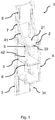
- Fig. 1 shows schematically and exemplarily an embodiment of the folding staircase in an unfolded state, wherein Fig. 1 For better visualization, the wall to which the folding staircase is attached does not show.
- the folding staircase 1 comprises in this embodiment, three steps 2, each step each having a top 21 and a bottom 22.
- the folding staircase 1 on a holding system 34, that has a fastening element 3 and a support member 4.
- a fastening element 3 and a support element 4 are provided on each side of the step 2.
- the respective two fastening elements 3 and support elements 4 are constructed substantially the same.
- Substantially equ also implies that the elements perform the same function and have the same components and construction elements but may, if necessary, have a mirror-inverted arrangement of the individual components or construction elements.
- individual components of the elements in the figures are also denoted by the same symbols, for reasons of clarity not all components are designated on each side.
- the provision of two attachment and support elements in the form shown here increases the stability of the folding staircase. In the following each one of the elements will be described in more detail.
- the fastening element 3 is formed in this embodiment by an elongated metal construction, wherein the fastening element 3 is formed in an upper portion in the form of a rail member 8.
- the fastener 3 is adapted to be inserted into designated omissions in a wall and the Folding stairs thus permanently and stably on the wall to arrange, in particular to attach.
- the support element 4 has a first section 41 and a second section 42, wherein the first and second sections 41, 42 are designed as a metal tube with a rectangular cross-section.
- the first portion 41 and the second portion 42 of the support member 4 are interconnected by a hinge 9.
- the hinge 9 thus allows the first portion 41 and the second portion 42 to perform a rotational movement against each other.
- the first portion 41 and thus the support member 4 via a rotary push joint 7 with the rail portion 8 of the fastener 3 is connected.
- the rotary thrust joint 7 allows the first portion 41 of the support member 4 both a rotational movement relative to the fastener 3 and a pushing movement vertically along the fastener.
- the stairs 2 are mounted by means of a first pivot 5 on the fastener 3 and thus on the wall. Furthermore, the steps 2 are attached by means of a second pivot 6 to the second section 42 of the support element 4. In the case of the top step, the pivot 9 for connecting the first portion 41 and the second portion 42 of the support member 4 and the second pivot 6 of the stairs 2 coincide and form a common hinge.
- Fig. 2 shows schematically and exemplarily the same embodiment of the folding staircase as Fig. 1 , where the folding staircase in Fig. 2 is in a state between the unfolded and the folded state.
- the same elements of the folding staircase are denoted by the same symbols in both figures.
- the folding staircase allows a user to use the top 21 of the stairs 2 as a climbing aid. If such a climbing aid is not needed, the user transfers the folding staircase 1 of the unfolded state in the closed state.
- a user accesses one of the stair steps 2 or the second section 42 of the support element 4 and pushes them upwards in the direction of the wall.
- the rotary push joint 7 and thus also the support element 4 is moved upward.
- the first pivot 5, with which the stairs 2 are attached to the fastener 3 limit the movement of the stairs 2 to a rotational movement about the hinge 5.
- the remote from the wall parts of the stairs. 2 and thus also the second hinges 6 of the stairs 2 move semicircular towards the wall.
- This movement is supported and stabilized by the rotary push joint 7 and the swivel joint 9.
- Fig. 3 illustrates that in the folded state of the rail portion 8 of the fastener 3 is arranged to receive the support member 4 completely.
- the rotary push hinge 7 of the support member 4 is in its highest position, and the hinge 9 is stretched, that is, the first portion 41 and the second portion 42 of the support member 4 are aligned in a straight line.
- the stairs 2 are thus embedded in the wall, and the bottom surfaces 22 of the stairs are aligned with the fastener 3 and thus also on the wall.
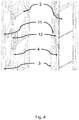
- the fastening element 3 has a first magnet 11 and the support element 4 a second magnet 12.
- the magnets are on an inner side of the rail portion 8 of the fastener 3 and within the tube of the second portion 42 of the support member 4 from the outside for the user not visible.
- the arrangement of the first magnet 11 and the second magnet 12 is such that, as shown in the right part of Figure 4, in the closed state, the magnets are close to each other. Furthermore, the magnets are poled in such a way that, in the closed state, an attractive force is produced between the first magnet 11 and the second magnet 12. This keeps the folding staircase in a closed state.
- the attractive force between the first magnet 11 and the second magnet 12 is chosen so that minor disturbances, such as occur when moving the motorhome, do not trigger folding the folding stairs, while it is easy for a user, for example by a small Jerk at one of the steps, to release the magnets from each other and thus to transfer the folding staircase in the unfolded state.
Landscapes
- Engineering & Computer Science (AREA)
- Mechanical Engineering (AREA)
- Steps, Ramps, And Handrails (AREA)
Abstract
Description
- Die Erfindung bezieht sich auf eine Klapptreppe. Des Weiteren bezieht sich die Erfindung auf ein Reisemobil, das eine erfindungsgemäße Klapptreppe aufweist.
- In Reisemobilen, wie zum Beispiel Wohnmobilen, Wohnwagen oder Pferdetransportern mit einem Wohnbereich, ist es üblich, aus Platzgründen eine Schlafgelegenheit in einer gewissen Höhe vorzusehen, zum Beispiel oberhalb der Fahrerkabine im Falle eines Wohnmobils oder oberhalb der Stalleinheit im Falle eines Pferdetransporters. Um solche Schlafgelegenheiten zu erreichen, muss aufgrund der Höhe der Schlafgelegenheit eine Aufstiegshilfe vorgesehen werden. Es ist bekannt, eine Aufstiegshilfe in Form einer Treppe vorzusehen, wobei es üblich ist, dass die Treppe nur bei Gebrauch, zum Beispiel mit Haken, an der Schlafmöglichkeit befestigt wird. Werden die Aufstiegshilfen nicht benötigt, zum Beispiel tagsüber, müssen sie in einem anderen Teil des Reisemobils verstaut werden, um nicht die Bewegungsfreiheit der Benutzer des Reisemobils einzuschränken. Das Verstauen der Aufstiegshilfe, die üblicherweise sehr stabil und damit schwer ausgestaltet ist, kostet Stauraum, der somit nicht anderweitig in den ohnehin beengten Verhältnissen eines Reisemobils verwendet werden kann. Es besteht daher der Bedarf, eine Aufstiegshilfe vorzusehen, die, wenn sie nicht gebraucht wird, möglichst wenig Platz und somit Stauraum benötigt.
- Es ist daher eine Aufgabe der vorliegenden Erfindung, eine Klapptreppe bereitzustellen, die, wenn sie nicht benötigt wird, möglichst wenig Platz und damit Stauraum einnimmt.
- Diese Aufgabe wird gelöst durch eine Klapptreppe, wobei die Klapptreppe aufweist:
- wenigstens eine Treppenstufe mit einer Oberseite und einer Unterseite,
- ein Haltesystem, geeignet zum Halten der wenigstens einen Treppenstufe, wobei die wenigstens eine Treppenstufe beweglich am Haltesystem angebracht ist,
- Dadurch, dass das Haltesystem dazu geeignet ist, an einer Wand angebracht zu werden, wobei in dem aufgeklappten Zustand die Oberseite der wenigstens einen Treppenstufe horizontal zu der Wand ausgerichtet ist, um eine Aufstiegshilfe zu bilden und wobei in dem zugeklappten Zustand die Unterseite der wenigstens einen Treppenstufe parallel mit der Wand ausgerichtet ist, kann die Treppe, wenn sie nicht gebraucht wird, an der Wand verbleiben, wobei die Treppe in diesem Zustand keinerlei zusätzlichen Stauraum benötigt.
- In einer bevorzugten Ausführungsform ist die Klapptreppe dazu geeignet, so an der Wand angebracht zu werden, insbesondere in die Wand eingelassen zu werden, dass in dem zugeklappten Zustand die Unterseite der wenigstens einen Treppenstufe in einer Flucht mit der Wand ausgerichtet ist. Das bedeutet, dass die Unterseite der wenigstens einen Treppenstufe mit der Wand eine Fläche bildet, die Klapptreppe also vollständig in der Wand verschwindet. Für eine solche Konstruktion ist es notwendig, dass zum Anbringen der Klapptreppe eine gewisse Aussparung in der Wand vorgesehen wird, in der die Klapptreppe angebracht werden kann. Bei einer solchen Anbringung muss eine gewisse konstruktionsbedingte Abweichung von der angestrebten Fluchtung zwischen der Wand und der Unterseite der wenigstens einen Treppenstufe toleriert werden. Eine solche Abweichung liegt bevorzugt in einem Bereich von weniger als 5 cm.
- Es wird weiter bevorzugt, dass das Haltesystem weiter ein Befestigungselement, das dazu geeignet ist, die Klapptreppe an der Wand anzubringen, und ein Stützelement aufweist, wobei das Stützelement dazu geeignet ist, in dem aufgeklappten Zustand die wenigstens eine Treppenstufe zu stützen. Insbesondere ist das Befestigungselement dazu geeignet, die Klapptreppe dauerhaft, das heißt ohne die Möglichkeit für den Benutzer, die Klapptreppe von der Wand zu entfernen, an der Wand anzubringen. Das Befestigungselement ist bevorzugt dazu geeignet, in die Wand eingelassen zu werden, um die Klapptreppe an der Wand anzubringen. Dabei bedeutet "in die Wand einlassen", dass in der Wand Aussparungen vorgesehen werden, in die das Befestigungselement und die Klapptreppe eingebracht werden können. Das Stützelement ist bevorzugt beweglich am Befestigungselement angeordnet.
- Es wird bevorzugt, dass die wenigstens eine Treppenstufe mittels eines ersten Drehgelenkes an dem Befestigungselement und mittels eines zweiten Drehgelenkes an dem Stützelement angebracht ist.
- Es wird weiter bevorzugt, dass das Stützelement mittels eines Drehschubgelenkes am Befestigungselement angebracht ist und das Drehschubgelenk dazu eingerichtet ist, eine Schubbewegung des Stützelements vertikal entlang des Befestigungselements zu erlauben. Insbesondere wird bevorzugt, dass das Befestigungselement einen Schienenabschnitt aufweist, wobei das Stützelement mittels des Drehschubgelenkes an dem Schienenabschnitt des Befestigungselements angebracht ist und das Stützelement dazu geeignet ist, sich mittels des Drehschubgelenkes bei einem Übergang zwischen dem zugeklappten und dem aufgeklappten Zustand entlang des Schienenabschnitts zu bewegen. Insbesondere wird bevorzugt, dass der Schienenabschnitt des Befestigungselements dazu eingerichtet ist, in dem zugeklappten Zustand das Stützelement vollständig aufzunehmen, um ein Ausrichten der Unterseite der wenigstens einen Treppenstufe an der Wand zu ermöglichen.
- In einer weiteren Ausführungsform weist das Stützelement weiter einen ersten Abschnitt und einen zweiten Abschnitt auf, wobei der erste Abschnitt beweglich an dem Befestigungselement und die wenigstens eine Treppenstufe beweglich an dem zweiten Abschnitt angeordnet ist, wobei der erste Abschnitt mit dem zweiten Abschnitt über ein Drehgelenk verbunden ist und in einem aufgeklappten Zustand der erste Abschnitt einen Winkel mit der Wand bildet und der zweite Abschnitt vertikal parallel zur Wand verläuft. Dabei ist der Winkel, den der erste Abschnitt mit der Wand bildet größer als 0° und kleiner als 90°. In einer besonders bevorzugten Ausführungsform beträgt der Winkel 30°. In einer weiteren besonders bevorzugten Ausführungsform sind der erste Abschnitt und der zweite Abschnitt jeweils als Rohr oder Stange mit rechteckigem Querschnitt ausgebildet.
- Des Weiteren wird bevorzugt, dass das Befestigungselement einen ersten Magneten aufweist und das Stützelement einen zweiten Magneten aufweist, wobei die Magneten verdeckt so angeordnet und eingerichtet sind, dass in dem zugeklappten Zustand die Magneten die Klapptreppe in dem zugeklappten Zustand halten.
- Es wird außerdem bevorzugt, dass sich der Abstand zwischen der Oberseite und der Unterseite der wenigstens einen Treppenstufe im aufgeklappten Zustand mit zunehmender Entfernung von der Wand verringert. Dies hat den Vorteil, dass die Treppenstufen im zugeklappten Zustand den sich hinter den Stufen befindlichen Teil der Wand bzw. Teil der Rückwand der Aussparung in der Wand nicht berühren. Während einer Fahrt mit einem Reisemobil, in das die Klapptreppe eingebaut ist, können so die Stufen nicht durch kleine Bewegungen oder durch Ruckeln die Wand auf Dauer beschädigen oder abnutzen. Außerdem wird so bei unruhiger Fahrt ein Klappern der Stufen an der Wand vermieden.
- Insbesondere wird bevorzugt, dass die Klapptreppe mehrere Treppenstufen aufweist, wobei Treppenstufen unterhalb einer obersten Treppenstufe bei gleichbleibender Stufenbreite eine größere Trittfläche aufweisen als die oberste Treppenstufe. Die Trittfläche wird dabei gebildet aus der Stufenbreite und der Stufentiefe, wobei die Stufenbreite parallel zur Wand und die Stufentiefe von der Wand bis zur von der Wand abgewandten Kante der Stufe gemessen wird. Besonders bevorzugt weisen die Treppenstufen unterhalb der obersten Treppenstufe eine größere Stufentiefe als die oberste Treppenstufe auf.
- In einer weiteren bevorzugten Ausführungsform ist das Befestigungselement ein erstes Befestigungselement und das Haltesystem weist ein zweites Befestigungselement auf, wobei das erste und zweite Befestigungselement entsprechend zueinander ausgeführt sind und das erste und zweite Befestigungselement jeweils auf gegenüberliegenden Seiten der wenigstens einen Treppenstufe angeordnet ist. Weiter wird bevorzugt, dass das Stützelement ein erstes Stützelement ist und das Haltesystem weiter ein zweites Stützelement aufweist, wobei das erste und das zweite Stützelement entsprechend zueinander ausgeführt sind und das erste und das zweite Stützelement jeweils auf gegenüberliegenden Seiten der wenigstens einen Treppenstufe angeordnet ist.
- Die oben genannte Aufgabe wird des Weiteren durch ein Reisemobil, insbesondere einen Pferdetransporter mit einem Wohnbereich, das eine Wand mit einer erfindungsgemäßen Klapptreppe aufweist, gelöst.
- Es sollte verstanden werden, dass die Klapptreppe nach Anspruch 1 und die bewegliche Wohneinheit nach Anspruch 15 ähnliche und/oder identische bevorzugte Ausführungsformen aufweisen, wie sie insbesondere in den abhängigen Ansprüchen definiert sind.
- Im Folgenden werden Ausführungsformen der Erfindung unter Bezugnahme auf nachfolgende Figuren beschrieben, wobei
- Fig. 1
- schematisch und exemplarisch eine Ausführungsform der Klapptreppe in einem aufgeklappten Zustand zeigt,
- Fig. 2
- schematisch und exemplarisch eine Ausführungsform der Klapptreppe in einem Zustand zwischen dem aufgeklappten und dem zugeklappten Zustand zeigt,
- Fig. 3
- schematisch und exemplarisch eine Ausführungsform der Klapptreppe im zugeklappten Zustand zeigt, und
- Fig. 4
- schematisch und exemplarisch einen vergrößerten Ausschnitt einer Ausführungsform der Klapptreppe in einem halb aufgeklappten und einem zugeklappten Zustand zeigt.
-
Fig. 1 zeigt schematisch und exemplarisch eine Ausführungsform der Klapptreppe in einem aufgeklappten Zustand, wobeiFig. 1 für eine bessere Darstellbarkeit die Wand, an der die Klapptreppe angebracht ist, nicht zeigt. Die Klapptreppe 1 umfasst in dieser Ausführungsform drei Treppenstufen 2, wobei jede Treppenstufe jeweils eine Oberseite 21 und eine Unterseite 22 aufweist. Weiter weist die Klapptreppe 1 ein Haltesystem 34 auf, dass ein Befestigungselement 3 und ein Stützelement 4 aufweist. - In der hier gezeigten Ausführungsform sind jeweils ein Befestigungselement 3 und ein Stützelement 4 auf jeder Seite der Treppenstufe 2 vorgesehen. Dabei sind die jeweiligen beiden Befestigungselemente 3 und Stützelemente 4 im Wesentlichen gleich aufgebaut. Im Wesentlichen gleich beinhaltet, dass die Elemente die jeweils gleiche Funktion erfüllen und die gleichen Bestandteile und Konstruktionselemente aufweisen, aber, wenn notwendig, eine spiegelverkehrte Anordnung der einzelnen Bestandteile oder Konstruktionselemente aufweisen können. Aus diesem Grund werden einzelne Bestandteile der Elemente in den Figuren auch mit den gleichen Symbolen bezeichnet, wobei aus Gründen der Übersichtlichkeit nicht auf jeder Seite alle Bestandteile bezeichnet werden. Das Vorsehen von jeweils zwei Befestigungs- und Stützelementen in der hier gezeigten Form erhöht die Stabilität der Klapptreppe. Im Folgenden wird jeweils eins der Elemente genauer beschrieben.
- Das Befestigungselement 3 wird in dieser Ausführungsform durch eine längliche Metallkonstruktion gebildet, wobei das Befestigungselement 3 in einem oberen Abschnitt in Form eines Schienenelements 8 ausgebildet ist. Das Befestigungselement 3 ist dazu geeignet, in dafür vorgesehene Auslassungen in einer Wand eingelassen zu werden und die Klapptreppe somit dauerhaft und stabil an der Wand anzuordnen, insbesondere zu befestigen.
- Das Stützelement 4 weist in der hier gezeigten Ausführungsform einen ersten Abschnitt 41 und einen zweiten Abschnitt 42 auf, wobei der erste und der zweite Abschnitt 41, 42 als Metallrohr mit rechteckigem Querschnitt ausgeführt sind. Der erste Abschnitt 41 und der zweite Abschnitt 42 des Stützelements 4 sind durch ein Drehgelenk 9 miteinander verbunden. Das Drehgelenk 9 ermöglicht es dem ersten Abschnitt 41 und dem zweiten Abschnitt 42 somit, gegeneinander eine Drehbewegung aufzuführen. Weiter ist der erste Abschnitt 41 und somit das Stützelement 4 über ein Drehschubgelenk 7 mit dem Schienenabschnitt 8 des Befestigungselements 3 verbunden. Das Drehschubgelenk 7 ermöglicht dem ersten Abschnitt 41 des Stützelements 4 sowohl eine Drehbewegung bezüglich des Befestigungselements 3 als auch eine Schubbewegung vertikal entlang des Befestigungselements 3.
- Die Treppenstufen 2 sind mittels eines ersten Drehgelenkes 5 am Befestigungselement 3 und somit an der Wand angebracht. Des Weiteren sind die Treppenstufen 2 mittels eines zweiten Drehgelenkes 6 am zweiten Abschnitt 42 des Stützelements 4 angebracht. Im Falle der obersten Treppenstufe fallen das Drehgelenk 9 zur Verbindung des ersten Abschnitts 41 und des zweiten Abschnitts 42 des Stützelements 4 und das zweite Drehgelenk 6 der Treppenstufen 2 zusammen und bilden ein gemeinsames Drehgelenk.
- Die erfindungsgemäße Funktion der Klapptreppe beim Übergang zwischen dem aufgeklappten Zustand, wie in
Fig. 1 gezeigt, und dem zugeklappten Zustand, wie inFig. 3 gezeigt, wird im Folgenden anhand vonFig. 2 verdeutlicht.Fig. 2 zeigt schematisch und exemplarisch die gleiche Ausführungsform der Klapptreppe wieFig. 1 , wobei sich die Klapptreppe inFig. 2 in einem Zustand zwischen dem aufgeklappten und dem zugeklappten Zustand befindet. Somit sind auch in beiden Figuren gleiche Elemente der Klapptreppe mit gleichen Symbolen bezeichnet. In dem aufgeklappten Zustand, wie er inFig. 1 gezeigt ist, ermöglicht die Klapptreppe einem Benutzer die Verwendung der Oberseite 21 der Treppenstufen 2 als Aufstiegshilfe. Wird eine derartige Aufstiegshilfe nicht benötigt, überführt der Benutzer die Klapptreppe 1 von dem aufgeklappten Zustand in den zugeklappten Zustand. Dabei greift ein Benutzer zum Beispiel eine der Treppenstufen 2 oder den zweiten Abschnitt 42 des Stützelements 4 und schiebt diese nach oben in Richtung Wand. Dadurch wird das Drehschubgelenk 7 und somit auch das Stützelement 4 nach oben bewegt. Gleichzeitig begrenzen die ersten Drehgelenke 5, mit denen die Treppenstufen 2 am Befestigungselement 3 angebracht sind, die Bewegung der Treppenstufen 2 zu einer Drehbewegung um das Drehgelenk 5. Die von der Wand entfernten Teile der Treppenstufen 2 und somit auch die zweiten Drehgelenke 6 der Treppenstufen 2 bewegen sich halbkreisförmig in Richtung Wand. Diese Bewegung wird durch das Drehschubgelenk 7 und das Drehgelenk 9 unterstützt und stabilisiert. Am Ende dieser Bewegung befindet sich die Klapptreppe 1 in dem zugeklappten Zustand 1 wie inFig. 3 gezeigt. -
Fig. 3 verdeutlicht, dass in dem zugeklappten Zustand der Schienenabschnitt 8 des Befestigungselements 3 so eingerichtet ist, das Stützelement 4 vollständig aufzunehmen. In diesem Zustand befindet sich das Drehschubgelenk 7 des Stützelements 4 in seiner höchsten Position, und das Drehgelenk 9 ist gestreckt, das heißt, der erste Abschnitt 41 und der zweite Abschnitt 42 des Stützelements 4 sind in einer geraden Linie ausgerichtet. Die Treppenstufen 2 sind somit in die Wand eingelassen, und die Unterseiten 22 der Treppenstufen sind an dem Befestigungselement 3 und somit auch an der Wand ausgerichtet. - Damit die Klapptreppe 1 im zugeklappten Zustand nicht durch schon geringe Störungen, zum Beispiel beim Bewegen, insbesondere Fahren, des Reisemobils in den aufgeklappten Zustand übergeht, sind verdeckt im Befestigungselement 3 und dem Stützelement 4 Magneten 11, 12 vorgesehen. Zur Verdeutlichung der Anbringung der Magneten zeigt
Fig. 4 schematisch und exemplarisch einen vergrößerten Ausschnitt der Klapptreppe in einem halb aufgeklappten und einem geschlossenen Zustand, wobei zum Sichtbarmachen der vorgesehenen Magneten Teile der äußeren Wände des Befestigungselements 3 und des Stützelements 4 entfernt wurden. In dieser Ausführungsform weist das Befestigungselement 3 einen ersten Magneten 11 auf und das Stützelement 4 einen zweiten Magneten 12. Die Magneten sind dabei auf einer Innenseite des Schienenabschnitts 8 des Befestigungselements 3 und innerhalb des Rohres des zweiten Abschnitts 42 des Stützelements 4 von außen für den Nutzer nicht sichtbar angeordnet. Des Weiteren erfolgt die Anordnung des ersten Magneten 11 und des zweiten Magneten 12 so, dass, wie im rechten Teil der Abbildung 4 gezeigt, im geschlossenen Zustand die Magneten nahe beieinanderliegen. Die Magneten sind des Weiteren dabei so gepolt, dass im zugeklappten Zustand eine anziehende Kraft zwischen dem ersten Magneten 11 und dem zweiten Magneten 12 entsteht. Dadurch wird die Klapptreppe in einem geschlossenen Zustand gehalten. Die anziehende Kraft zwischen dem ersten Magneten 11 und dem zweiten Magneten 12 wird dabei so gewählt, dass kleinere Störungen, wie sie zum Beispiel beim Bewegen des Reisemobils auftreten, kein Aufklappen der Klapptreppe auslösen, während es dennoch einem Benutzer leichtfällt, zum Beispiel durch einen kleinen Ruck an einer der Treppenstufen, die Magneten voneinander zu lösen und die Klapptreppe somit in den aufgeklappten Zustand zu überführen. - In den Ansprüchen schließen die Wörter "aufweisen" und "umfassen" nicht andere Elemente aus, und die unbestimmten Artikel "ein" schließen eine Mehrzahl nicht aus.
- Die Bezugszeichen in den Ansprüchen sind nicht derart zu verstehen, dass der Gegenstand und der Schutzbereich der Ansprüche durch diese Bezugszeichen eingeschränkt sind.
Claims (15)
- Klapptreppe, wobei die Klapptreppe (1) aufweist:wenigstens eine Treppenstufe (2) mit einer Oberseite (21) und einer Unterseite (22),ein Haltesystem (34), geeignet zum Halten der wenigstens einen Treppenstufe (2), wobei die wenigstens eine Treppenstufe (2) beweglich am Haltesystem (34) angebracht ist,
wobei die Klapptreppe (1) einen aufgeklappten Zustand und einen zugeklappten Zustand aufweist,
wobei die Klapptreppe dadurch gekennzeichnet ist, dass das Haltesystem (34) dazu geeignet ist, die Klapptreppe so an einer vertikalen Wand anzubringen, dass in dem aufgeklappten Zustand die Oberseite (21) der wenigstens einen Treppenstufe (2) horizontal ausgerichtet ist, um eine Aufstiegshilfe zu bilden, und in dem zugeklappten Zustand die Unterseite (22) der wenigstens einen Treppenstufe (2) parallel mit der Wand ausgerichtet ist. - Klapptreppe nach Anspruch 1, wobei die Klapptreppe dazu geeignet ist, so in die Wand eingelassen zu werden, dass in dem zugeklappten Zustand die Unterseite (22) der wenigstens einen Treppenstufe (2) in einer Flucht mit der Wand ausgerichtet ist.
- Klapptreppe nach Anspruch 1 oder 2, wobei das Haltesystem (34) weiter aufweist:ein Befestigungselement (3), wobei das Befestigungselement (3) geeignet ist, die Klapptreppe (1) an der Wand anzubringen, undein Stützelement (4), wobei das Stützelement (4) dazu geeignet ist, in dem aufgeklappten Zustand die wenigstens eine Treppenstufe (2) zu stützen.
- Klapptreppe nach Anspruch 3, wobei das Stützelement (4) beweglich am Befestigungselement (3) angeordnet ist.
- Klapptreppe nach einem der Ansprüche 3 oder 4, wobei die wenigstens eine Treppenstufe (2) mittels eines ersten Drehgelenkes (5) an dem Befestigungselement (3) und mittels eines zweiten Drehgelenkes (6) an dem Stützelement (4) angebracht ist.
- Klapptreppe nach einem der Ansprüche 3 bis 5, wobei das Stützelement (4) mittels eines Drehschubgelenkes (7) am Befestigungselement (3) angebracht ist und das Drehschubgelenk (7) dazu eingerichtet ist, eine Schubbewegung des Stützelements (4) vertikal entlang des Befestigungselements (3) zu erlauben.
- Klapptreppe nach Anspruch 6, wobei das Befestigungselement (3) einen Schienenabschnitt (8) aufweist, wobei das Stützelement (4) mittels des Drehschubgelenkes (7) an dem Schienenabschnitt (8) des Befestigungselements (3) angebracht ist und das Stützelement (4) dazu geeignet ist, sich mittels des Drehschubgelenkes (7) bei einem Übergang zwischen dem zugeklappten und dem aufgeklappten Zustand entlang des Schienenabschnitts (8) zu bewegen.
- Klapptreppe nach Anspruch 7, wobei der Schienenabschnitt (8) des Befestigungselements (3) dazu eingerichtet ist, in dem zugeklappten Zustand das Stützelement (4) vollständig aufzunehmen, um ein Ausrichten der Unterseite (22) der wenigstens einen Treppenstufe (2) an der Wand zu ermöglichen.
- Klapptreppe nach einem der Ansprüche 3 bis 8, wobei das Stützelement (4) weiter aufweist:einen ersten Abschnitt (41), wobei der erste Abschnitt beweglich an dem Befestigungselement (3) angeordnet ist, undeinen zweiten Abschnitt (42), wobei die wenigstens eine Treppenstufe (2) beweglich an dem zweiten Abschnitt (42) angeordnet ist,
wobei der erste Abschnitt (41) mit dem zweiten Abschnitt (42) über ein Drehgelenk (9) verbunden ist und in einem aufgeklappten Zustand der erste Abschnitt (41) einen Winkel mit der Wand bildet und der zweite Abschnitt (42) vertikal parallel zur Wand verläuft. - Klapptreppe nach einem der Ansprüche 3 bis 9, wobei das Befestigungselement (3) einen ersten Magneten (11) aufweist und das Stützelement (4) einen zweiten Magneten (12) aufweist, wobei die Magneten (11, 12) verdeckt so angeordnet und eingerichtet sind, dass in dem zugeklappten Zustand die Magneten die Klapptreppe (1) in dem zugeklappten Zustand halten.
- Klapptreppe nach einem der vorherigen Ansprüche, wobei sich der Abstand zwischen der Oberseite (21) und der Unterseite (22) der wenigstens einen Treppenstufe (2) im aufgeklappten Zustand mit zunehmender Entfernung von der Wand verringert.
- Klapptreppe nach einem der vorherigen Ansprüche, wobei die Klapptreppe mehrere Treppenstufen (2) aufweist, wobei Treppenstufen unterhalb einer obersten Treppenstufe bei gleichbleibender Stufenbreite eine größere Trittfläche aufweisen als die oberste Treppenstufe.
- Klapptreppe nach einem der Ansprüche 3 bis 12, wobei das Befestigungselement ein erstes Befestigungselement ist und das Haltesystem (34) ein zweites Befestigungselement aufweist, wobei das erste und zweite Befestigungselement entsprechend zueinander ausgeführt sind und das erste und zweite Befestigungselement jeweils auf gegenüberliegenden Seiten der wenigstens einen Treppenstufe (2) angeordnet sind.
- Klapptreppe nach Anspruch 13, wobei das Stützelement (4) ein erstes Stützelement ist und Haltesystem (34) weiter ein zweites Stützelement aufweist, wobei das erste und das zweite Stützelement entsprechend zueinander ausgeführt sind und das erste und das zweite Stützelement jeweils auf gegenüberliegenden Seiten der wenigstens einen Treppenstufe (2) angeordnet sind.
- Reisemobil, insbesondere ein Pferdetransporter mit einem Wohnbereich, das eine Wand mit einer Klapptreppe nach einem der vorherigen Ansprüche aufweist.
Applications Claiming Priority (1)
| Application Number | Priority Date | Filing Date | Title |
|---|---|---|---|
| DE202018101786.1U DE202018101786U1 (de) | 2018-03-29 | 2018-03-29 | Klapptreppe |
Publications (2)
| Publication Number | Publication Date |
|---|---|
| EP3546294A1 true EP3546294A1 (de) | 2019-10-02 |
| EP3546294B1 EP3546294B1 (de) | 2021-01-20 |
Family
ID=62069289
Family Applications (1)
| Application Number | Title | Priority Date | Filing Date |
|---|---|---|---|
| EP19164737.9A Active EP3546294B1 (de) | 2018-03-29 | 2019-03-22 | Klapptreppe |
Country Status (2)
| Country | Link |
|---|---|
| EP (1) | EP3546294B1 (de) |
| DE (1) | DE202018101786U1 (de) |
Citations (5)
| Publication number | Priority date | Publication date | Assignee | Title |
|---|---|---|---|---|
| US3067835A (en) * | 1960-08-05 | 1962-12-11 | Francis E Valley | Folding step |
| US4720116A (en) * | 1986-11-24 | 1988-01-19 | Williams Michael G | Storable stairway and platform apparatus for recreational vehicles |
| SE464234B (sv) * | 1988-09-15 | 1991-03-25 | Tony Thorberg | Med haallardel foerenad stege till lastfordon |
| US5397143A (en) * | 1992-02-25 | 1995-03-14 | Bird; Ronald C. | Folding steps |
| US20090020360A1 (en) * | 2007-07-18 | 2009-01-22 | May Brian A | Landing ladder |
Family Cites Families (1)
| Publication number | Priority date | Publication date | Assignee | Title |
|---|---|---|---|---|
| EP3415413B1 (de) * | 2017-06-15 | 2020-02-19 | AIRBUS HELICOPTERS DEUTSCHLAND GmbH | Fahrzeug mit integrierter einsteigeinheit mit faltbarer verkleidung |
-
2018
- 2018-03-29 DE DE202018101786.1U patent/DE202018101786U1/de not_active Expired - Lifetime
-
2019
- 2019-03-22 EP EP19164737.9A patent/EP3546294B1/de active Active
Patent Citations (5)
| Publication number | Priority date | Publication date | Assignee | Title |
|---|---|---|---|---|
| US3067835A (en) * | 1960-08-05 | 1962-12-11 | Francis E Valley | Folding step |
| US4720116A (en) * | 1986-11-24 | 1988-01-19 | Williams Michael G | Storable stairway and platform apparatus for recreational vehicles |
| SE464234B (sv) * | 1988-09-15 | 1991-03-25 | Tony Thorberg | Med haallardel foerenad stege till lastfordon |
| US5397143A (en) * | 1992-02-25 | 1995-03-14 | Bird; Ronald C. | Folding steps |
| US20090020360A1 (en) * | 2007-07-18 | 2009-01-22 | May Brian A | Landing ladder |
Also Published As
| Publication number | Publication date |
|---|---|
| EP3546294B1 (de) | 2021-01-20 |
| DE202018101786U1 (de) | 2018-04-12 |
Similar Documents
| Publication | Publication Date | Title |
|---|---|---|
| DE69901167T2 (de) | Klapptisch | |
| EP3287305B1 (de) | Scherengestell und übergang mit scherengestell | |
| DE4026391C2 (de) | Klapptisch für Wohnmobile | |
| DE202010004302U1 (de) | Sitz für Tribünen | |
| DE69817855T2 (de) | Schutzkonstruktion gegen wettereinflüsse | |
| EP3546294B1 (de) | Klapptreppe | |
| DE102017128562A1 (de) | Regalbox mit Arretieranschlägen | |
| AT398517B (de) | Schublade | |
| DE102017217088A1 (de) | Seitliche Begrenzung für eine Ladeflächenverlängerung | |
| DE69712378T2 (de) | Zusammenbau von Schubladenelementen bestehend aus Tragschiene, Laufschiene und Gehäuse | |
| DE19544305A1 (de) | Höhenverstellbare Runge mit Schiebling | |
| EP0172146A1 (de) | Rückziehbares Verschwindbett | |
| EP3347299B1 (de) | Führungsschiene für eine aufzugsanlage | |
| DE2614435C2 (de) | Höhenveränderbarer Stützfuß für Möbel | |
| DE102013223128A1 (de) | Kinderhochstuhl | |
| DE102010038165A1 (de) | Bauteilverbindung, Trägerkonstruktion, insbesondere Brücke, und Verfahren zur Verbindung von Bauteilen | |
| DE102012104190A1 (de) | Zugdeichsel für einen Nutzfahrzeuganhänger | |
| AT507691A2 (de) | Regalbauelement und ein solches einhaltendes regal | |
| EP1283129B1 (de) | Klapptreppe für Wohnwagen oder Wohnmobile | |
| DE202022102035U1 (de) | Kabeltragsegment | |
| DE102007016834A1 (de) | Einrichtung zum Befestigen eines Warenkorbes auf einem Einkaufswagen sowie Einkaufswagen hierzu | |
| DE202016000219U1 (de) | Auszugseinheit für ein Möbelstück mit zwei verbundenen Schubladen | |
| DE102012220012A1 (de) | Einrichtung zur Befestigung eines Laufstegs an einer Faserbahnmaschine, Laufsteg für eine Faserbahnmaschine und Verfahren zur Handhabung eines Laufstegs in Verbindung mit einer Faserbahn | |
| DE102022103032A1 (de) | Haus | |
| DE102015000206A1 (de) | Befestigungsvorrichtung für Absperrholme an Pfosten von Absperreinrichtungen |
Legal Events
| Date | Code | Title | Description |
|---|---|---|---|
| PUAI | Public reference made under article 153(3) epc to a published international application that has entered the european phase |
Free format text: ORIGINAL CODE: 0009012 |
|
| STAA | Information on the status of an ep patent application or granted ep patent |
Free format text: STATUS: THE APPLICATION HAS BEEN PUBLISHED |
|
| AK | Designated contracting states |
Kind code of ref document: A1 Designated state(s): AL AT BE BG CH CY CZ DE DK EE ES FI FR GB GR HR HU IE IS IT LI LT LU LV MC MK MT NL NO PL PT RO RS SE SI SK SM TR |
|
| AX | Request for extension of the european patent |
Extension state: BA ME |
|
| STAA | Information on the status of an ep patent application or granted ep patent |
Free format text: STATUS: REQUEST FOR EXAMINATION WAS MADE |
|
| 17P | Request for examination filed |
Effective date: 20200402 |
|
| RBV | Designated contracting states (corrected) |
Designated state(s): AL AT BE BG CH CY CZ DE DK EE ES FI FR GB GR HR HU IE IS IT LI LT LU LV MC MK MT NL NO PL PT RO RS SE SI SK SM TR |
|
| RIC1 | Information provided on ipc code assigned before grant |
Ipc: B60R 3/02 20060101AFI20200625BHEP |
|
| GRAP | Despatch of communication of intention to grant a patent |
Free format text: ORIGINAL CODE: EPIDOSNIGR1 |
|
| STAA | Information on the status of an ep patent application or granted ep patent |
Free format text: STATUS: GRANT OF PATENT IS INTENDED |
|
| INTG | Intention to grant announced |
Effective date: 20200804 |
|
| GRAS | Grant fee paid |
Free format text: ORIGINAL CODE: EPIDOSNIGR3 |
|
| GRAA | (expected) grant |
Free format text: ORIGINAL CODE: 0009210 |
|
| STAA | Information on the status of an ep patent application or granted ep patent |
Free format text: STATUS: THE PATENT HAS BEEN GRANTED |
|
| AK | Designated contracting states |
Kind code of ref document: B1 Designated state(s): AL AT BE BG CH CY CZ DE DK EE ES FI FR GB GR HR HU IE IS IT LI LT LU LV MC MK MT NL NO PL PT RO RS SE SI SK SM TR |
|
| REG | Reference to a national code |
Ref country code: GB Ref legal event code: FG4D Free format text: NOT ENGLISH |
|
| REG | Reference to a national code |
Ref country code: CH Ref legal event code: EP |
|
| REG | Reference to a national code |
Ref country code: DE Ref legal event code: R096 Ref document number: 502019000706 Country of ref document: DE |
|
| REG | Reference to a national code |
Ref country code: AT Ref legal event code: REF Ref document number: 1356116 Country of ref document: AT Kind code of ref document: T Effective date: 20210215 |
|
| REG | Reference to a national code |
Ref country code: IE Ref legal event code: FG4D Free format text: LANGUAGE OF EP DOCUMENT: GERMAN |
|
| REG | Reference to a national code |
Ref country code: NL Ref legal event code: FP |
|
| REG | Reference to a national code |
Ref country code: LT Ref legal event code: MG9D |
|
| PG25 | Lapsed in a contracting state [announced via postgrant information from national office to epo] |
Ref country code: BG Free format text: LAPSE BECAUSE OF FAILURE TO SUBMIT A TRANSLATION OF THE DESCRIPTION OR TO PAY THE FEE WITHIN THE PRESCRIBED TIME-LIMIT Effective date: 20210420 Ref country code: HR Free format text: LAPSE BECAUSE OF FAILURE TO SUBMIT A TRANSLATION OF THE DESCRIPTION OR TO PAY THE FEE WITHIN THE PRESCRIBED TIME-LIMIT Effective date: 20210120 Ref country code: FI Free format text: LAPSE BECAUSE OF FAILURE TO SUBMIT A TRANSLATION OF THE DESCRIPTION OR TO PAY THE FEE WITHIN THE PRESCRIBED TIME-LIMIT Effective date: 20210120 Ref country code: GR Free format text: LAPSE BECAUSE OF FAILURE TO SUBMIT A TRANSLATION OF THE DESCRIPTION OR TO PAY THE FEE WITHIN THE PRESCRIBED TIME-LIMIT Effective date: 20210421 Ref country code: PT Free format text: LAPSE BECAUSE OF FAILURE TO SUBMIT A TRANSLATION OF THE DESCRIPTION OR TO PAY THE FEE WITHIN THE PRESCRIBED TIME-LIMIT Effective date: 20210520 Ref country code: NO Free format text: LAPSE BECAUSE OF FAILURE TO SUBMIT A TRANSLATION OF THE DESCRIPTION OR TO PAY THE FEE WITHIN THE PRESCRIBED TIME-LIMIT Effective date: 20210420 Ref country code: LT Free format text: LAPSE BECAUSE OF FAILURE TO SUBMIT A TRANSLATION OF THE DESCRIPTION OR TO PAY THE FEE WITHIN THE PRESCRIBED TIME-LIMIT Effective date: 20210120 |
|
| PG25 | Lapsed in a contracting state [announced via postgrant information from national office to epo] |
Ref country code: LV Free format text: LAPSE BECAUSE OF FAILURE TO SUBMIT A TRANSLATION OF THE DESCRIPTION OR TO PAY THE FEE WITHIN THE PRESCRIBED TIME-LIMIT Effective date: 20210120 Ref country code: RS Free format text: LAPSE BECAUSE OF FAILURE TO SUBMIT A TRANSLATION OF THE DESCRIPTION OR TO PAY THE FEE WITHIN THE PRESCRIBED TIME-LIMIT Effective date: 20210120 Ref country code: PL Free format text: LAPSE BECAUSE OF FAILURE TO SUBMIT A TRANSLATION OF THE DESCRIPTION OR TO PAY THE FEE WITHIN THE PRESCRIBED TIME-LIMIT Effective date: 20210120 Ref country code: SE Free format text: LAPSE BECAUSE OF FAILURE TO SUBMIT A TRANSLATION OF THE DESCRIPTION OR TO PAY THE FEE WITHIN THE PRESCRIBED TIME-LIMIT Effective date: 20210120 |
|
| PG25 | Lapsed in a contracting state [announced via postgrant information from national office to epo] |
Ref country code: IS Free format text: LAPSE BECAUSE OF FAILURE TO SUBMIT A TRANSLATION OF THE DESCRIPTION OR TO PAY THE FEE WITHIN THE PRESCRIBED TIME-LIMIT Effective date: 20210520 |
|
| REG | Reference to a national code |
Ref country code: DE Ref legal event code: R097 Ref document number: 502019000706 Country of ref document: DE |
|
| PG25 | Lapsed in a contracting state [announced via postgrant information from national office to epo] |
Ref country code: SM Free format text: LAPSE BECAUSE OF FAILURE TO SUBMIT A TRANSLATION OF THE DESCRIPTION OR TO PAY THE FEE WITHIN THE PRESCRIBED TIME-LIMIT Effective date: 20210120 Ref country code: CZ Free format text: LAPSE BECAUSE OF FAILURE TO SUBMIT A TRANSLATION OF THE DESCRIPTION OR TO PAY THE FEE WITHIN THE PRESCRIBED TIME-LIMIT Effective date: 20210120 Ref country code: EE Free format text: LAPSE BECAUSE OF FAILURE TO SUBMIT A TRANSLATION OF THE DESCRIPTION OR TO PAY THE FEE WITHIN THE PRESCRIBED TIME-LIMIT Effective date: 20210120 Ref country code: MC Free format text: LAPSE BECAUSE OF FAILURE TO SUBMIT A TRANSLATION OF THE DESCRIPTION OR TO PAY THE FEE WITHIN THE PRESCRIBED TIME-LIMIT Effective date: 20210120 |
|
| PLBE | No opposition filed within time limit |
Free format text: ORIGINAL CODE: 0009261 |
|
| STAA | Information on the status of an ep patent application or granted ep patent |
Free format text: STATUS: NO OPPOSITION FILED WITHIN TIME LIMIT |
|
| PG25 | Lapsed in a contracting state [announced via postgrant information from national office to epo] |
Ref country code: DK Free format text: LAPSE BECAUSE OF FAILURE TO SUBMIT A TRANSLATION OF THE DESCRIPTION OR TO PAY THE FEE WITHIN THE PRESCRIBED TIME-LIMIT Effective date: 20210120 Ref country code: SK Free format text: LAPSE BECAUSE OF FAILURE TO SUBMIT A TRANSLATION OF THE DESCRIPTION OR TO PAY THE FEE WITHIN THE PRESCRIBED TIME-LIMIT Effective date: 20210120 Ref country code: RO Free format text: LAPSE BECAUSE OF FAILURE TO SUBMIT A TRANSLATION OF THE DESCRIPTION OR TO PAY THE FEE WITHIN THE PRESCRIBED TIME-LIMIT Effective date: 20210120 |
|
| 26N | No opposition filed |
Effective date: 20211021 |
|
| PG25 | Lapsed in a contracting state [announced via postgrant information from national office to epo] |
Ref country code: IE Free format text: LAPSE BECAUSE OF NON-PAYMENT OF DUE FEES Effective date: 20210322 Ref country code: LU Free format text: LAPSE BECAUSE OF NON-PAYMENT OF DUE FEES Effective date: 20210322 Ref country code: AL Free format text: LAPSE BECAUSE OF FAILURE TO SUBMIT A TRANSLATION OF THE DESCRIPTION OR TO PAY THE FEE WITHIN THE PRESCRIBED TIME-LIMIT Effective date: 20210120 Ref country code: ES Free format text: LAPSE BECAUSE OF FAILURE TO SUBMIT A TRANSLATION OF THE DESCRIPTION OR TO PAY THE FEE WITHIN THE PRESCRIBED TIME-LIMIT Effective date: 20210120 |
|
| PG25 | Lapsed in a contracting state [announced via postgrant information from national office to epo] |
Ref country code: SI Free format text: LAPSE BECAUSE OF FAILURE TO SUBMIT A TRANSLATION OF THE DESCRIPTION OR TO PAY THE FEE WITHIN THE PRESCRIBED TIME-LIMIT Effective date: 20210120 |
|
| PG25 | Lapsed in a contracting state [announced via postgrant information from national office to epo] |
Ref country code: IT Free format text: LAPSE BECAUSE OF FAILURE TO SUBMIT A TRANSLATION OF THE DESCRIPTION OR TO PAY THE FEE WITHIN THE PRESCRIBED TIME-LIMIT Effective date: 20210120 |
|
| PG25 | Lapsed in a contracting state [announced via postgrant information from national office to epo] |
Ref country code: IS Free format text: LAPSE BECAUSE OF FAILURE TO SUBMIT A TRANSLATION OF THE DESCRIPTION OR TO PAY THE FEE WITHIN THE PRESCRIBED TIME-LIMIT Effective date: 20210520 |
|
| REG | Reference to a national code |
Ref country code: CH Ref legal event code: PL |
|
| PG25 | Lapsed in a contracting state [announced via postgrant information from national office to epo] |
Ref country code: LI Free format text: LAPSE BECAUSE OF NON-PAYMENT OF DUE FEES Effective date: 20220331 Ref country code: CH Free format text: LAPSE BECAUSE OF NON-PAYMENT OF DUE FEES Effective date: 20220331 |
|
| P01 | Opt-out of the competence of the unified patent court (upc) registered |
Effective date: 20230420 |
|
| PG25 | Lapsed in a contracting state [announced via postgrant information from national office to epo] |
Ref country code: CY Free format text: LAPSE BECAUSE OF FAILURE TO SUBMIT A TRANSLATION OF THE DESCRIPTION OR TO PAY THE FEE WITHIN THE PRESCRIBED TIME-LIMIT Effective date: 20210120 |
|
| PG25 | Lapsed in a contracting state [announced via postgrant information from national office to epo] |
Ref country code: HU Free format text: LAPSE BECAUSE OF FAILURE TO SUBMIT A TRANSLATION OF THE DESCRIPTION OR TO PAY THE FEE WITHIN THE PRESCRIBED TIME-LIMIT; INVALID AB INITIO Effective date: 20190322 |
|
| GBPC | Gb: european patent ceased through non-payment of renewal fee |
Effective date: 20230322 |
|
| PG25 | Lapsed in a contracting state [announced via postgrant information from national office to epo] |
Ref country code: GB Free format text: LAPSE BECAUSE OF NON-PAYMENT OF DUE FEES Effective date: 20230322 |
|
| PG25 | Lapsed in a contracting state [announced via postgrant information from national office to epo] |
Ref country code: GB Free format text: LAPSE BECAUSE OF NON-PAYMENT OF DUE FEES Effective date: 20230322 |
|
| PG25 | Lapsed in a contracting state [announced via postgrant information from national office to epo] |
Ref country code: MK Free format text: LAPSE BECAUSE OF FAILURE TO SUBMIT A TRANSLATION OF THE DESCRIPTION OR TO PAY THE FEE WITHIN THE PRESCRIBED TIME-LIMIT Effective date: 20210120 |
|
| PG25 | Lapsed in a contracting state [announced via postgrant information from national office to epo] |
Ref country code: MT Free format text: LAPSE BECAUSE OF FAILURE TO SUBMIT A TRANSLATION OF THE DESCRIPTION OR TO PAY THE FEE WITHIN THE PRESCRIBED TIME-LIMIT Effective date: 20210120 |
|
| REG | Reference to a national code |
Ref country code: AT Ref legal event code: MM01 Ref document number: 1356116 Country of ref document: AT Kind code of ref document: T Effective date: 20240322 |
|
| PGFP | Annual fee paid to national office [announced via postgrant information from national office to epo] |
Ref country code: DE Payment date: 20250409 Year of fee payment: 7 |
|
| PG25 | Lapsed in a contracting state [announced via postgrant information from national office to epo] |
Ref country code: AT Free format text: LAPSE BECAUSE OF NON-PAYMENT OF DUE FEES Effective date: 20240322 |
|
| PG25 | Lapsed in a contracting state [announced via postgrant information from national office to epo] |
Ref country code: TR Free format text: LAPSE BECAUSE OF FAILURE TO SUBMIT A TRANSLATION OF THE DESCRIPTION OR TO PAY THE FEE WITHIN THE PRESCRIBED TIME-LIMIT Effective date: 20210120 |
|
| PGFP | Annual fee paid to national office [announced via postgrant information from national office to epo] |
Ref country code: AT Payment date: 20260410 Year of fee payment: 5 |
|
| PGFP | Annual fee paid to national office [announced via postgrant information from national office to epo] |
Ref country code: BE Payment date: 20260323 Year of fee payment: 8 |
|
| PGFP | Annual fee paid to national office [announced via postgrant information from national office to epo] |
Ref country code: NL Payment date: 20260323 Year of fee payment: 8 |
|
| PGFP | Annual fee paid to national office [announced via postgrant information from national office to epo] |
Ref country code: FR Payment date: 20260324 Year of fee payment: 8 |