EP3546283B1 - Modularer fahrzeugsitzeinsatz, modulares sitzsystem und modulares sitzverfahren - Google Patents
Modularer fahrzeugsitzeinsatz, modulares sitzsystem und modulares sitzverfahren Download PDFInfo
- Publication number
- EP3546283B1 EP3546283B1 EP19164549.8A EP19164549A EP3546283B1 EP 3546283 B1 EP3546283 B1 EP 3546283B1 EP 19164549 A EP19164549 A EP 19164549A EP 3546283 B1 EP3546283 B1 EP 3546283B1
- Authority
- EP
- European Patent Office
- Prior art keywords
- vehicle
- shell
- insert
- vehicle body
- modular
- Prior art date
- Legal status (The legal status is an assumption and is not a legal conclusion. Google has not performed a legal analysis and makes no representation as to the accuracy of the status listed.)
- Active
Links
- 238000000034 method Methods 0.000 title claims description 13
- 238000009826 distribution Methods 0.000 claims description 19
- 238000003860 storage Methods 0.000 claims description 17
- 230000005540 biological transmission Effects 0.000 claims description 3
- 230000001939 inductive effect Effects 0.000 claims description 3
- 230000003287 optical effect Effects 0.000 claims description 3
- 230000007246 mechanism Effects 0.000 description 26
- 210000000078 claw Anatomy 0.000 description 10
- 230000008859 change Effects 0.000 description 4
- 239000002184 metal Substances 0.000 description 4
- 230000008901 benefit Effects 0.000 description 3
- 239000000835 fiber Substances 0.000 description 3
- 229920000049 Carbon (fiber) Polymers 0.000 description 2
- 230000015572 biosynthetic process Effects 0.000 description 2
- 239000004917 carbon fiber Substances 0.000 description 2
- 238000003780 insertion Methods 0.000 description 2
- 230000037431 insertion Effects 0.000 description 2
- 238000004519 manufacturing process Methods 0.000 description 2
- 239000000463 material Substances 0.000 description 2
- VNWKTOKETHGBQD-UHFFFAOYSA-N methane Chemical compound C VNWKTOKETHGBQD-UHFFFAOYSA-N 0.000 description 2
- 239000004033 plastic Substances 0.000 description 2
- 229920003023 plastic Polymers 0.000 description 2
- 230000029305 taxis Effects 0.000 description 2
- 206010010144 Completed suicide Diseases 0.000 description 1
- 241000272168 Laridae Species 0.000 description 1
- 239000002131 composite material Substances 0.000 description 1
- 238000009434 installation Methods 0.000 description 1
- 230000003993 interaction Effects 0.000 description 1
- 230000033001 locomotion Effects 0.000 description 1
- 239000000203 mixture Substances 0.000 description 1
- 230000008569 process Effects 0.000 description 1
- 229920001169 thermoplastic Polymers 0.000 description 1
- 239000004416 thermosoftening plastic Substances 0.000 description 1
Images



Classifications
-
- B—PERFORMING OPERATIONS; TRANSPORTING
- B60—VEHICLES IN GENERAL
- B60N—SEATS SPECIALLY ADAPTED FOR VEHICLES; VEHICLE PASSENGER ACCOMMODATION NOT OTHERWISE PROVIDED FOR
- B60N2/00—Seats specially adapted for vehicles; Arrangement or mounting of seats in vehicles
- B60N2/005—Arrangement or mounting of seats in vehicles, e.g. dismountable auxiliary seats
- B60N2/015—Attaching seats directly to vehicle chassis
- B60N2/01508—Attaching seats directly to vehicle chassis using quick release attachments
- B60N2/01516—Attaching seats directly to vehicle chassis using quick release attachments with locking mechanisms
-
- B—PERFORMING OPERATIONS; TRANSPORTING
- B60—VEHICLES IN GENERAL
- B60N—SEATS SPECIALLY ADAPTED FOR VEHICLES; VEHICLE PASSENGER ACCOMMODATION NOT OTHERWISE PROVIDED FOR
- B60N2/00—Seats specially adapted for vehicles; Arrangement or mounting of seats in vehicles
- B60N2/24—Seats specially adapted for vehicles; Arrangement or mounting of seats in vehicles for particular purposes or particular vehicles
- B60N2/242—Bus seats
-
- B—PERFORMING OPERATIONS; TRANSPORTING
- B60—VEHICLES IN GENERAL
- B60N—SEATS SPECIALLY ADAPTED FOR VEHICLES; VEHICLE PASSENGER ACCOMMODATION NOT OTHERWISE PROVIDED FOR
- B60N2/00—Seats specially adapted for vehicles; Arrangement or mounting of seats in vehicles
- B60N2/005—Arrangement or mounting of seats in vehicles, e.g. dismountable auxiliary seats
-
- B—PERFORMING OPERATIONS; TRANSPORTING
- B60—VEHICLES IN GENERAL
- B60N—SEATS SPECIALLY ADAPTED FOR VEHICLES; VEHICLE PASSENGER ACCOMMODATION NOT OTHERWISE PROVIDED FOR
- B60N2/00—Seats specially adapted for vehicles; Arrangement or mounting of seats in vehicles
- B60N2/68—Seat frames
- B60N2/686—Panel like structures
-
- B—PERFORMING OPERATIONS; TRANSPORTING
- B60—VEHICLES IN GENERAL
- B60N—SEATS SPECIALLY ADAPTED FOR VEHICLES; VEHICLE PASSENGER ACCOMMODATION NOT OTHERWISE PROVIDED FOR
- B60N3/00—Arrangements or adaptations of other passenger fittings, not otherwise provided for
- B60N3/02—Arrangements or adaptations of other passenger fittings, not otherwise provided for of hand grips or straps
-
- B—PERFORMING OPERATIONS; TRANSPORTING
- B60—VEHICLES IN GENERAL
- B60R—VEHICLES, VEHICLE FITTINGS, OR VEHICLE PARTS, NOT OTHERWISE PROVIDED FOR
- B60R16/00—Electric or fluid circuits specially adapted for vehicles and not otherwise provided for; Arrangement of elements of electric or fluid circuits specially adapted for vehicles and not otherwise provided for
- B60R16/02—Electric or fluid circuits specially adapted for vehicles and not otherwise provided for; Arrangement of elements of electric or fluid circuits specially adapted for vehicles and not otherwise provided for electric constitutive elements
- B60R16/0207—Wire harnesses
- B60R16/0215—Protecting, fastening and routing means therefor
-
- B—PERFORMING OPERATIONS; TRANSPORTING
- B60—VEHICLES IN GENERAL
- B60R—VEHICLES, VEHICLE FITTINGS, OR VEHICLE PARTS, NOT OTHERWISE PROVIDED FOR
- B60R22/00—Safety belts or body harnesses in vehicles
- B60R22/18—Anchoring devices
- B60R22/195—Anchoring devices with means to tension the belt in an emergency, e.g. means of the through-anchor or splitted reel type
- B60R22/1951—Anchoring devices with means to tension the belt in an emergency, e.g. means of the through-anchor or splitted reel type characterised by arrangements in vehicle or relative to seat belt
-
- B—PERFORMING OPERATIONS; TRANSPORTING
- B60—VEHICLES IN GENERAL
- B60R—VEHICLES, VEHICLE FITTINGS, OR VEHICLE PARTS, NOT OTHERWISE PROVIDED FOR
- B60R22/00—Safety belts or body harnesses in vehicles
- B60R22/18—Anchoring devices
- B60R22/26—Anchoring devices secured to the seat
-
- B—PERFORMING OPERATIONS; TRANSPORTING
- B60—VEHICLES IN GENERAL
- B60R—VEHICLES, VEHICLE FITTINGS, OR VEHICLE PARTS, NOT OTHERWISE PROVIDED FOR
- B60R7/00—Stowing or holding appliances inside vehicle primarily intended for personal property smaller than suit-cases, e.g. travelling articles, or maps
- B60R7/04—Stowing or holding appliances inside vehicle primarily intended for personal property smaller than suit-cases, e.g. travelling articles, or maps in driver or passenger space, e.g. using racks
- B60R7/043—Stowing or holding appliances inside vehicle primarily intended for personal property smaller than suit-cases, e.g. travelling articles, or maps in driver or passenger space, e.g. using racks mounted on or under a seat
Definitions
- the present invention relates to vehicle seating in general and more particularly relates to a modular vehicle seat configuration and a modular vehicle seat arrangement as well as a method of providing a vehicle seat arrangement.
- Vehicle seats have been provided as individual units which are inserted into a vehicle body and fixed inside the body. Typically, vehicle seats are designed for particular vehicle models. The vehicle is dimensioned or sized in advance and the vehicle seat is adapted to the design. This presents limitations with regard to changing seating configurations for a vehicle and particularly limits scalability and the ability to provide multiple seating configurations across vehicles of various sizes and types. Changes as to vehicle seats may be extensively limited based on the vehicle type and size. Vehicle seats that are designed for one vehicle type or vehicle size typically are not immediately usable in a different vehicle type or vehicle size.
- US 3 873 155 A discloses a modular vehicle seating insert comprising an insert shell structure to be received within a vehicle body and having a vehicle body facing surface and a vehicle interior facing surface, wherein the vehicle interior facing surface defines seat module receiving portions; vehicle connection features operatively provided at a side of the vehicle body facing surface of the shell structure for cooperation with vehicle body connection features to fix the shell structure to the vehicle body; and seat module connection features, each of the seat module connection features being associated with one of the seat module receiving portions
- a modular vehicle seating insert comprising a shell structure to be received within a vehicle body.
- the shell insert structure has a vehicle body facing surface and a vehicle interior facing surface.
- the vehicle interior facing surface defines seat module receiving portions.
- Vehicle connection features are operatively provided at a side of the vehicle body facing surface of the shell structure for cooperation with vehicle body connection features to fix the shell structure to the vehicle body.
- the shell insert structure includes seat module connection features. Each of the seat module connection features is associated with one of the seat module receiving portions.
- the vehicle connection features each comprise a clamping connector for clamping connection with a connection point bar supported by the vehicle body.
- the shell may support a handle grip, extending outwardly from the shell structure and positioned at a side of each of the seat module receiving portions.
- the handle grip and other features may be molded into the shell structure, at the time of forming the shell structure.
- a seat belt retractor assembly may be fixed to the shell or a seat belt anchor may be fixed to the shell. Further, both a seat belt retractor assembly may be fixed to the shell and a seat belt anchor may be fixed to the shell.
- the shell may define a central portion separating the seat module receiving portions.
- the seat module connection features may each comprise a connection point bar extending from a shell sidewall to the central portion.
- the shell may comprise one or more passages.
- the passages may comprise an access passage between a shell body facing surface side and a shell vehicle interior facing surface side.
- the passages may provide one or more distribution paths along an extent of the shell.
- the passages may comprise one or more access passages between a vehicle body facing surface side and a vehicle interior facing surface side and providing a distribution path along an extent of the shell.
- Power attachments may be provided comprising a connector end disposed adjacent to or extending out of the access passage and wires extending through the distribution path.
- the insert shell may further comprise a storage space defined by a portion of the vehicle body facing surface.
- a modular vehicle seating system comprising a vehicle body with vehicle interior connection features and a modular vehicle seating insert according to the invention.
- the vehicle connection features each comprise a vehicle clamping connector for clamping connection with a vehicle connection point bar supported by the vehicle body.
- the vehicle interior connection features comprise vehicle support points each supporting a vehicle connection point bar.
- the vehicle clamping connector clampingly connects with the vehicle connection point bar to fix the shell to the vehicle body.
- the modular vehicle seating system advantageously further comprises a seat module comprising a seat base and a seat clamping connector.
- the seat module connection features each comprise a connection point bar supported by the shell and provided at each of the seat module receiving portions.
- the seat clamping connector clampingly connects with the connection point bar to fix the seat module at one of the seat module receiving portions.
- the modular vehicle seating system may advantageously include transmission path attachments with a connector end disposed adjacent to or extending out of the access passage and wires extending through the distribution path.
- the shell may have an insert component receiving space defined by a portion of the vehicle body facing surface.
- An insert component may be connected to vehicle power and vehicle system features via the connector and wires.
- the insert component may be one or more of a credit/debit card reader, an ac power connection, an inductive power charge facility, a data connector, a wireless data transceiver, a video display, an optical reader, a fold out tray device, a mobile device support and similar useful features.
- a modular vehicle seating method includes providing a vehicle body with vehicle interior connection features and also providing a modular vehicle seating insert shell.
- the insert shell includes a shell structure to be received within a vehicle body.
- the shell structure has a vehicle body facing surface and a vehicle interior facing surface.
- the vehicle interior facing surface defines seat module receiving portions with seat module connection features associated with the seat module receiving portions.
- a vehicle connection feature is operatively provided at a side of the vehicle body facing surface of the shell structure for cooperation with the vehicle interior connection features to fix the shell structure to the vehicle body and seat module connection features.
- the vehicle connection features are provided as a plurality of vehicle clamping connectors.
- the vehicle interior connection features each comprise vehicle support points, each supporting a vehicle connection point bar supported by the vehicle body.
- the method further comprises clampingly connecting the vehicle connection point bar with the vehicle clamping connector to fix the shell to the vehicle body.
- Seat modules are provided, each comprising a seat base and a seat clamping connector.
- the shell structure defines seat module receiving portions with the seat module connection features each comprising a connection point bar supported by the shell.
- the method further comprises clampingly connecting the clamping connector to the connection point bar to fix the seat module at one of the seat module receiving portions.
- a modular vehicle seating insert shell generally designated 10 is preformed so as to be placed in a vehicle body, prior to seating being installed in the vehicle body.
- the vehicle insert shell 10 comprises a shell structure to be received within a vehicle body.
- the shell structure is formed of a composite such as a fiber and thermoplastic mix, carbon fiber, metal sheet and combinations of these.
- the shell structure may be formed of other robust material(s) allowing the insert shell 10 to have shape integrity - so as to be dimensionally stable - to be fixed within a vehicle body and to support seating components and other features as described herein.
- the shell insert 10 has a tub shape with interior facing surfaces which will at least partially form interior surfaces of the vehicle.
- the interior facing surfaces also define a left side seat module receiving portion 12 and a right side seat module receiving portion 14.
- the interior facing surfaces include a right side interior wall 16 and a left side interior wall 18.
- the side interior walls 16 and 18 will be at least partially covered by seating modules (described below) but will also form side interior surfaces of the vehicle.
- the shell insert 10 of the figures provides two seat module receiving portions 12, 14, other arrangements are possible, such as three seat module receiving portions or one bench seat receiving portion.
- the disclosed embodiments, with two seat module receiving portions 12, 14, have the advantage of providing a center console region 20, which may be used for functional purposes such as storage or receiving insert components described further below.
- the center console region 20 comprises supporting structures in the form of center console walls including a right side wall (the direction being based on the shell insert 10 facing forward with regard to a direction of vehicle travel) and a left side wall.
- the right side center console wall has a right side wall surface 22 and an insert receiving space right wall surface 28.
- the left side center console wall has a left side wall surface 24 and an insert receiving space left wall surface 26.
- the side wall surfaces 22 and 24 face the respective seat module receiving portions 12 and 14.
- the wall surfaces 28 and 26 in cooperation with a center console insert receiving space bottom surface 30 define a lower receiving space.
- the lower receiving space may be provided as storage, with appropriate doors or may be provided to receive an insert component 96, discussed below.
- the shell insert 10 has a bottom or shell lower inner surfaces 38 which may also delimit a storage space, namely underneath a vehicle seat module 90.
- the insert shell 10 may have other surface features such as a contoured shell upper interior surface 42 and shell inner surface armrests 44.
- the insert shell 10 is dimensionally stable with a shell forward edge 32 that extends along a base of the shell insert 10 and along each side to a shell upper edge 34.
- the shell insert 10 has a vehicle body facing surface 36 which extends at each side and wraps around to the rear side of the shell insert 10.
- the vehicle body facing surface 36 is intended to abut or face side walls and a rear wall/bulkhead 72 of the vehicle body ( Figures 4 and 5 ).
- Shell insert 10 also has a lower surface 37 which abuts or faces a vehicle floor 70 ( Figures 4 and 5 ).
- the dimensionally stable nature of the insert shell 10 is such that the console walls with wall surfaces 22, 28 and 24, 26 and the interior walls 16 and 18 support connection point bars 40 that form a seat module connection feature.
- Each of the connection point bars 40 is associated with one of the seat module receiving portions 12 and 14. Further, two or more connection point bars 40 may be provided and supported at each of the seat module receiving portions 12 and 14.
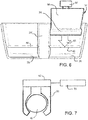
- FIG 3 shows an insert shell 10' including handle grips 46.
- the support connection bars 40 and the handle grips 46 may be molded in or configured and joined with the insert shell 10' during formation of the insert shell 10'.
- the handle grips 46 are particularly useful with a seating arrangement that provides for the insert shell 10' to face a similar insert shell 10', whereby the user of the seat opposite the handle may use the handle grips 46 to help themselves in and out of the seat and potentially also into and out of the vehicle.
- the handle grips 46 of Figures 3 and 8 show two configuration alternatives of support of an upper position of the handle grips 46.
- the upper position is supported somewhat outwardly of the wall 18 and at another side the upper portion is supported somewhat inwardly of the wall 16.
- the upper portion is supported by the respective wall and may advantageously be molded into the wall and be essentially in the respective wall.
- FIG. 2 shows a slightly modified version of the insert shell 10 wherein the center console 20' differs from the center counsel 20 previously described.
- the center console 20' forms a divider between seating regions defined by the left side seat module receiving portion 12 and a right side seat module receiving portion 14.
- the entire center console 20' may be used to provide storage space or a space for receiving one or more insert component.
- Figure 3 shows a center console region 20" that defines a center console storage space 52.
- the storage space 52 may include features such as shelves or hooks for supporting coats and the like. Additionally, a door may be provided to close the storage space 52.
- the modified insert shell 10' advantageously incorporates other additional features besides handles and storage features. For example, safety features may be provided including compartments holding airbags, which compartments are covered by suitable coverings allowing the airbags to the hidden and protected during non-use.
- the embodiment of Figure 3 further includes a seat belt retractor assembly 50.
- the seat belt retractor assembly 50 is fixed to the shell insert 10'.
- the retractor assembly 50 may be molded into the insert shell 10' or otherwise fixed to the shell insert 10' during the manufacturing of the insert shell 10'.
- a seat belt anchor may be fixed to the shell insert 10' or both a seat belt retractor assembly 50 is fixed to the shell insert 10' and a seat belt anchor is fixed to the shell insert 10'.
- a seat belt anchor may be connected to a strap portion which is in turn connected to a buckle clasp (not shown).
- Numerous other additional features may be partially formed in the insert shell 10' or may be fixed during manufacturing of the insert shell 10' or may be fixed to the insert shell 10" before or after the insert 10' is placed into the vehicle body.
- Figure 4 shows the vehicle floor surface 70 and a vehicle wall surface (or bulkhead surface) 72 which are configured with vehicle interior connection features 60, 64 and 62, 64 to fix the shell structure to the vehicle body.
- the shell insert includes vehicle connection features 80, 82 and 84 which are operatively provided at a side of the vehicle body facing surface of the shell structure 10, 10' or 10" (described further below) for cooperation with the vehicle interior connection features 60, 64 and 62, 64 to fix the shell structure to the vehicle body.
- the insert shell 10' is shown as transparent, so as to see the position of the shell 10' relative to the floor surface 70 and the wall surface 72.
- the shell insert 10, 10' or 10" is preferably provided as a prefabricated module with essentially all features present at the time it is inserted into the vehicle body.
- the vehicle body is preferably provided with at least one door opening of sufficient size to receive the shell insert 10, 10' and 10".
- the vehicle may be intended to be a taxi or multiple passenger carrying vehicle with relatively large door openings through which the shell insert 10, 10' and 10" can pass.
- the shell insert 10, 10' and 10" may be dropped into a portion of a vehicle body prior to fully forming the vehicle body.
- the vehicle body has an interior floor surface 70 which includes a vehicle floor connection feature recess 60.
- the vehicle body preferably also includes a vehicle wall surface or bulkhead surface 72 with vehicle bulkhead/wall connection feature recess 62.
- the vehicle body including the floor at the vehicle floor surface 70 and the wall at the wall surface 72 supports a connection point bar 64 at each of the recesses 60 and 62.
- the shell insert 10, 10' and 10" includes a plurality of clamping connector mechanisms 80, each with clamping claws 82.
- Figure 5 shows the interaction of one such clamping connector mechanism 80, including clamping claws 82, and the connection point bar 64, which is supported and held by the vehicle body.
- the mechanism 80 includes an actuating feature (engagement actuator(s)) such that upon placement of the shell insert 10, 10' and 10" in position relative to the floor surface 70 and the wall surface 72, the connection point bar 64 actuates a clamping, with the clamping claws 82 engaging around the connection point bar 64.
- the shell insert 10, 10' and 10" may be positioned relative to the floor surface 70 in the wall surface 72 and each of the clamping connector mechanisms 80 is actuated individually, with actuator 84, via access openings 53 discussed below.
- the clamping connection that is provided fixes the shell insert 10, 10' and 10" in position within the vehicle body and prevents movement of the shell insert 10, 10' and 10" relative to the floor surface 70 and relative to the wall surface 72.
- the clamping connector mechanisms 80 may include the actuator 84 which only clampingly connects the shell insert 10, 10' and 10" to the vehicle body or, in the alternative, the actuator 84 may be provided that is configured to also release the clamping connection of the shell insert 10, 10' and 10" to the vehicle body.
- the engagement actuator, the disengagement actuator and/or the engagement actuator and the disengagement actuator 84 may be provided at each mechanism 80 or may be a single actuator 84 connected to each mechanism 80.
- the shell insert 10, 10' and 10" positioned and fixed within the vehicle body, receives a modular vehicle seating insert 90 in each of the seat module receiving portions 12 and 14.
- a seating insert clamping connector mechanism 92 is provided that is connected to an underside of the seat base (cushion) 94 of the modular vehicle seating insert 90 ( Figure 7 ).
- the seating insert clamping connector mechanism 92 includes clamping claws 91 which clampingly connect the modular vehicle seating insert 90 to the connection point bar 40.
- plural connection point bars 40 may be provided at each receiving portion 12, 14 and plural connector mechanisms 92 may be provided at each seating insert 90.
- the seating insert clamping connector mechanism 92 may advantageously include a clamping actuator 93 to actuate the clamping mechanism 92 for fixing the modular vehicle seating insert 90 to the connection point bar 40 and releasing the modular vehicle seating insert 90 from the connection point bar 40.
- the actuation may be automatic, with the actuation of the clamping mechanism to have the clamping claws 91 engage the connection point bar 40 as the modular vehicle seating insert 90 is moved in a seating module insertion direction 95, to lock and fix the modular vehicle seating insert 90 to the connection point bar 40 ( Figure 6 ).
- the actuation via the clamping actuator 93 may be manually initiated. In each case this results in a fixing of the modular vehicle seating insert 90 to the shell insert 10, 10' and 10".
- the clamping actuator 93 of the seating insert clamping connector mechanism 92 may further allow for a disconnection based on the actuator 93 actuating the clamping mechanism 92 to release the clamping claws 91 of the clamping mechanism 92.
- a modular vehicle seating insert 90 may be swapped out for a different or new modular vehicle seating insert 90.
- a particular advantage of the shell insert 10, 10' and 10" is the ability to change out the particular modular vehicle seating insert 90 for another particular modular vehicle seating insert 90. This allows, among other things, the ability to change a configuration of the interior seating space of a vehicle and also allows the old seating inserts 90 to be swapped out for new seating inserts 90, e.g., after significant wear, to the original modular vehicle seating insert 90.
- the arrangement is believed to be particularly useful with autonomous vehicles that are taxis and/or standard vehicles, particularly taxis and vehicles carrying multiple passengers.
- FIG 8 shows a further embodiment of a shell insert 10".
- the shell insert 10" is essentially the same as the shell insert 10', except that shell insert 10" includes a center console region 20" with the space storage space 52 that is covered by a storage space cover door 56.
- the door 56 may be as simple hinge door with an actuator 58 which allows for controlled opening and potential locked closing of the door 56.
- the door 56 may also be comprised of slats and mounted on a roller for being deployed and retracted (garage door type).
- the shell insert 10" includes one or more access passages 53 which provide access to an engagement/disengagement actuator 84 of the clamping mechanism 80, allowing the engagement/disengagement actuator to be used to control a connection and/or a disconnection of the shell insert 10" to the vehicle body.
- the shell insert 10" may include other access passages 54, that allow access to a region behind the shell insert 10".
- the shell insert 10" also includes one or more distribution paths (channels) 55, either formed as a tubular distribution path between the interior facing surface of the shell 10" and the rear side surface facing walls of the vehicle body or the rear side surface facing the walls of the vehicle body may form a trough or channel.
- the distribution paths 55 are particularly useful for bringing power and/or a data connection to a location of the interior facing side of the shell insert 10".
- reference number 55 also designates power/data lines including power attachments comprising a connector end disposed adjacent to or extending out of the access passage and wires extending through the distribution path.
- one distribution path 55 may bring power and control signals to the access passage 54 at or below the seat module receiving portion to power and control motors associated with the modular vehicle seating insert 90. This can allow for a motorized adjustment of the position of the seating insert 90.
- the distribution path 55 which connects to the access passage 54 within the storage space 52 may be used for supplying ac power or a similar functional connection. Similar distribution path 55 and access passage 54 may be provided to supply a data or power connection to an insert component 96 positioned in the insert component receiving space of the center console.
- Data lines and/or power lines are advantageously routed as desired along and/or through the shell insert 10" such that one or more insert components may be located as desired to provide a number of features.
- the functionality of the provided insert components 96 includes one or more of: a credit/debit card reader; an ac power connection; an inductive power charge facility; a data connector; a wireless data transceiver; a video display; an optical reader; a fold out tray device; and a mobile device support. Further, any of the spaces defined by the shell insert 10" may be used for storage or instead may receive such an insert component 96.
- the door 56 as a closing door of a space and/or as a cover door of another insert component 96 has a surface including a touchscreen actuator or a physical button actuator 58 which changes the display, such as a display comprising a graphical user interface (GUI), allowing a passenger to interact with other features.
- GUI graphical user interface
- the door 56 is itself is a part of an insert component 96 and provides a touchscreen with one or more soft keys and/or actual button actuators 58.
- the soft keys and/or actual button actuators 58 provide actuation input of the user, which may trigger a signal providing input.
- the input may change information content on the touchscreen and provide a physical change, such as unlocking the storage door 56.
- a vehicle seating method which includes providing, namely forming, an insert shell 10, 10' or 10".
- the insert shell 10, 10' or 10" may be a plastic/fiber molded structure.
- Some features, such as the handle 46 and the connection point bar 40, are advantageously molded in during the formation process.
- Other materials may be used to form the insert shell 10, 10' or 10" including a metal such as sheet-metal, carbon fiber and various combinations of metal, plastics and fibers.
- a vehicle body is provided with an opening sufficiently large enough for the insert shell 10, 10' or 10" to pass through the opening. If the vehicle is a taxi or similar vehicle, sliding doors, gull wing doors or a set of same vehicle side doors with opposite hinges (forward door with suicide door hinge and rearward door with standard opening door in combination as a set), may present an opening size which is more than sufficient for the passage of an insert shell 10, 10' or 10".
- This vehicle body is further provided with vehicle interior connection features 60, 62, 64, as described above.
- the vehicle insert shell 10, 10' or 10" is provided with the vehicle connection features, each comprising a vehicle clamping connector mechanism 80 with engageable clamping claws 82, as described above.
- the vehicle interior connection features each comprise vehicle support points, each supporting a vehicle connection point bar 64 supported by the vehicle body, as described above.
- the features may be switched with the insert shell 10, 10' or 10" having the connection point bars 64 and the floor recess 62 and the wall or vehicle body frame recesses 62 supporting the clamping connector mechanism 80 with engageable clamping claws 82.
- the insert shell 10, 10' or 10" is inserted within the vehicle body. If multiple insert shells 10, 10' or 10" are provided, each insert shell 10, 10' or 10" is inserted into the insert body, one at a time.
- the insert shell 10, 10' or 10" is fixed to the vehicle body by clampingly connecting the vehicle connection point bar with the vehicle clamping connector to fix the shell to the vehicle body.
- the method further includes providing a seat module 90 comprising a seat base and a seat clamping connector mechanism 92 as described above.
- the shell 10, 10' or 10" defines preferably two or more seat module receiving portions 12 and 14.
- Each provided seat module 90 includes connection features that comprise a connection point bar 40 supported by the shell insert 10, 10' or 10".
- the seat module 90 has one or more connection point bars that are engaged by one or more clamping connector mechanisms 92 supported by the shell insert 10, 10' or 10".
- each seat module 90 is clampingly connected to the shell insert 10, 10' or 10" by connecting the clamping claws of the seating insert clamping connector mechanism 92 to the connection point bar(s) 40 to fix the seat module 40 at one of the seat module receiving portions 12, 14 of the shell insert 10, 10' or 10".
Landscapes
- Engineering & Computer Science (AREA)
- Mechanical Engineering (AREA)
- Transportation (AREA)
- Aviation & Aerospace Engineering (AREA)
- Seats For Vehicles (AREA)
- Vehicle Step Arrangements And Article Storage (AREA)
Claims (14)
- Modularer Fahrzeugsitzeinsatz (10, 10', 10"), umfassend:eine Einsatzschalenstruktur zur Aufnahme innerhalb einer Fahrzeugkarosserie (70, 72), die eine der Fahrzeugkarosserie zugewandte Fläche (36) und eine dem Fahrzeuginneren zugewandte Fläche aufweist, wobei die dem Fahrzeuginneren zugewandte Fläche Sitzmodulaufnahmeabschnitte (12, 14) definiert;Fahrzeugverbindungsmerkmale (80, 82, 84), die wirksam auf einer Seite der der Fahrzeugkarosserie zugewandten Fläche (36) der Schalenstruktur bereitgestellt sind, um mit Fahrzeugkarosserieverbindungsmerkmalen (64) zusammenzuwirken, um die Schalenstruktur an der Fahrzeugkarosserie (70, 72) zu befestigen; undSitzmodulverbindungsmerkmale, wobei jedes der Sitzmodulverbindungsmerkmale einem der Sitzmodulaufnahmeabschnitte (12, 14) zugeordnet ist, dadurch gekennzeichnet, dassdie Fahrzeugverbindungsmerkmale (80, 82, 84) jeweils einen Klemmverbinder (80) zur Klemmverbindung mit einer von der Fahrzeugkarosserie (70, 72) gestützten Verbindungspunktstange (64) umfassen.
- Modularer Fahrzeugsitzeinsatz (10, 10', 10") nach Anspruch 1, wobei:die Schale einen mittleren Abschnitt definiert, der die Sitzmodulaufnahmeabschnitte (12, 14) trennt;die Sitzmodulverbindungsmerkmale jeweils eine Verbindungspunktstange (40) umfassen, die sich von einer Schalenseitenwand zum mittleren Abschnitt erstreckt.
- Modularer Fahrzeugsitzeinsatz (10', 10") nach Anspruch 1 oder 2, wobei die Schale einen Handgriff (46) stützt, der sich von der Schalenstruktur nach außen erstreckt und auf einer Seite jedes der Sitzmodulaufnahmeabschnitte (12, 14) positioniert ist.
- Modularer Fahrzeugsitzeinsatz (10', 10") nach einem der Ansprüche 1 bis 3, ferner umfassend eine an der Schale befestigte Sicherheitsgurtaufrollanordnung (50) oder eine an der Schale befestigte Sicherheitsgurtverankerung oder sowohl eine an der Schale befestigte Sicherheitsgurtaufrollanordnung (50) und eine an der Schale befestigte Sicherheitsgurtverankerung.
- Modularer Fahrzeugsitzeinsatz (10") nach einem der Ansprüche 1 bis 4, wobei die Schale einen Durchgang umfasst:der einen Zugangsdurchgang (53, 54) zwischen einer Fahrzeugkarosserie zugewandten Flächenseite und einer dem Fahrzeuginneren zugewandten Flächenseite bereitstellt oderder einen Verteilungsweg (55) entlang einer Ausdehnung der Schale bereitstellt oderder einen Zugangsdurchgang (53, 54) zwischen einer der Fahrzeugkarosserie zugewandten Flächenseite und einer dem Fahrzeuginneren zugewandten Flächenseite bereitstellt und einen Verteilungsweg (55) entlang einer Ausdehnung der Schale bereitstellt.
- Modularer Fahrzeugsitzeinsatz (10") nach einem der Ansprüche 1 bis 5, ferner umfassend Leistungsbefestigungen, umfassend ein Verbinderende, das neben dem Zugangsdurchgang (53, 54) angeordnet oder sich aus diesem heraus erstreckt, und Drähte, die sich durch den Verteilungsweg (55) erstrecken.
- Modularer Fahrzeugsitzeinsatz (10") nach einem der Ansprüche 1 bis 6, wobei die Einsatzschalenstruktur einen Aufbewahrungsraum (52) umfasst, der durch einen Abschnitt der der Fahrzeugkarosserie zugewandten Fläche (36) definiert ist.
- Modulares Fahrzeugsitzsystem, umfassend:eine Fahrzeugkarosserie (70, 72) mit Fahrzeuginnenverbindungsmerkmalen (60, 62, 64) undeinen modularen Fahrzeugsitzeinsatz (10, 10', 10") nach einem der Ansprüche 1 bis 7.
- Modulares Fahrzeugsitzsystem nach Anspruch 8, wobei:die Fahrzeugverbindungsmerkmale (80, 82, 84) jeweils einen Fahrzeugklemmverbinder (80) zur Klemmverbindung mit einer von der Fahrzeugkarosserie (70, 72) gestützten Fahrzeugverbindungspunktstange (64) umfassen; unddie Fahrzeuginnenverbindungsmerkmale (60, 62, 64) Fahrzeugstützpunkte umfassen, die jeweils eine Fahrzeugverbindungspunktstange (64) stützen; undder Fahrzeugklemmverbinder (80) klemmend mit der Fahrzeugverbindungspunktstange (64) verbunden ist, um die Schale an der Fahrzeugkarosserie (70, 72) zu befestigen.
- Modulares Fahrzeugsitzsystem nach Anspruch 9, ferner umfassend ein Sitzmodul (90), das eine Sitzbasis (94) und einen Sitzklemmverbinder (92) umfasst, wobei:die Sitzmodulverbindungsmerkmale jeweils eine Verbindungspunktstange (40) umfassen, die von der Schale gestützt wird und an jedem der Sitzmodulaufnahmeabschnitte (12, 14) bereitgestellt ist;der Sitzklemmverbinder klemmend mit der Verbindungspunktstange (40) verbunden ist, um das Sitzmodul an einem der Sitzmodulaufnahmeabschnitte (12, 14) zu befestigen.
- Modulares Fahrzeugsitzsystem nach einem der Ansprüche 9 oder 10, ferner umfassend Übertragungswegbefestigungen, umfassend ein Verbinderende, das neben dem Zugangsdurchgang angeordnet ist oder sich aus diesem heraus erstreckt, und Drähte, die sich durch den Verteilungsweg (55) erstrecken, wobei:die Schale einen Einsatzkomponentenaufnahmeraum (52) definiert, der durch einen Abschnitt der der Fahrzeugkarosserie zugewandten Fläche (36) definiert ist; unddie Einsatzkomponente (96) über den Verbinder und Drähte mit Leistungs- und Fahrzeugsystemmerkmalen verbunden ist.
- Modulares Fahrzeugsitzsystem nach einem der Ansprüche 9 bis 11, wobei die Einsatzkomponente (96) zumindest eine Komponente ist, die aus der Gruppe ausgewählt ist, die Folgendes umfasst:ein Kredit-/Debitkartenlesegerät;einen Wechselstromanschluss;eine Einrichtung zum induktiven Wiederaufladen;einen Datenverbinder;einen drahtlosen Datentransceiver;eine Videoanzeige;ein optisches Lesegerät;eine ausklappbare Muldenvorrichtung undeine Stütze für mobile Geräte.
- Modulares Fahrzeugsitzverfahren, umfassend die folgenden Schritte:Bereitstellen einer Fahrzeugkarosserie (70, 72) mit Fahrzeuginnenverbindungsmerkmalen (60, 62, 64);Bereitstellen eines modularen Fahrzeugsitzeinsatzes (10, 10', 10") nach einem der Ansprüche 1 bis 7;Bereitstellen der Fahrzeugverbindungsmerkmale (80, 82, 84), die jeweils einen Fahrzeugklemmverbinder (80) umfassen;Bereitstellen der Fahrzeuginnenverbindungsmerkmale (60, 62, 64), die jeweils Fahrzeugstützpunkte umfassen, die jeweils eine von der Fahrzeugkarosserie (70, 72) gestützte Fahrzeugverbindungspunktstange (64) stützen;Klemmverbinden der Fahrzeugverbindungspunktstange (64) mit dem Fahrzeugklemmverbinder (80), um die Schale an der Fahrzeugkarosserie (70, 72) zu befestigen;Bereitstellen eines Sitzmoduls (90), das eine Sitzbasis (94) und einen Sitzklemmverbinder (92) umfasst;Bereitstellen der Schale, um Sitzmodulaufnahmeabschnitte (12, 14) zu definieren;Bereitstellen der Sitzmodulverbindungsmerkmale, die jeweils eine von der Schale gestützte Verbindungspunktstange (40) umfassen; undKlemmverbinden des Klemmverbinders (92) mit der Verbindungspunktstange (40), um das Sitzmodul (90) an einem der Sitzmodulaufnahmeabschnitte (12, 14) zu befestigen.
- Verfahren nach Anspruch 13, wobei:die Schale einen Durchgang umfasst: der einen Zugangsdurchgang (53, 54) zwischen einer der Fahrzeugkarosserie zugewandten Flächenseite und einer dem Fahrzeuginneren zugewandten Flächenseite bereitstellt; oder der einen Verteilungsweg (55) entlang einer Ausdehnung der Schale bereitstellt; oder der einen Zugangsdurchgang zwischen einer der Fahrzeugkarosserie zugewandten Flächenseite und einer dem Fahrzeuginneren zugewandten Flächenseite bereitstellt und einen Verteilungsweg (55) entlang einer Ausdehnung der Schale bereitstellt;Übertragungswegbefestigungen bereitgestellt sind, umfassend ein Verbinderende, das neben dem Zugangsdurchgang (53, 54) angeordnet ist oder sich aus diesem heraus erstreckt, und Drähte, die sich durch den Verteilungsweg (55) erstrecken;die Schale einen Einsatzkomponentenaufnahmeraum (52) definiert, der durch einen Abschnitt der der Fahrzeugkarosserie zugewandten Fläche (36) definiert ist; undeine Einsatzkomponente (96) im Einsatzkomponentenaufnahmeraum (52) angeordnet und über den Verbinder und Drähte mit Leistungs- und Fahrzeugsystemmerkmalen verbunden ist.
Applications Claiming Priority (1)
| Application Number | Priority Date | Filing Date | Title |
|---|---|---|---|
| US15/938,582 US10625628B2 (en) | 2018-03-28 | 2018-03-28 | Modular vehicle seating insert, modular seating system and modular seating method |
Publications (2)
| Publication Number | Publication Date |
|---|---|
| EP3546283A1 EP3546283A1 (de) | 2019-10-02 |
| EP3546283B1 true EP3546283B1 (de) | 2020-09-09 |
Family
ID=65904298
Family Applications (1)
| Application Number | Title | Priority Date | Filing Date |
|---|---|---|---|
| EP19164549.8A Active EP3546283B1 (de) | 2018-03-28 | 2019-03-22 | Modularer fahrzeugsitzeinsatz, modulares sitzsystem und modulares sitzverfahren |
Country Status (3)
| Country | Link |
|---|---|
| US (1) | US10625628B2 (de) |
| EP (1) | EP3546283B1 (de) |
| CN (1) | CN110316025B (de) |
Families Citing this family (2)
| Publication number | Priority date | Publication date | Assignee | Title |
|---|---|---|---|---|
| US11414137B2 (en) * | 2020-02-12 | 2022-08-16 | GM Global Technology Operations LLC | Vehicle partition and method of manufacturing a vehicle |
| US11975644B2 (en) * | 2021-11-29 | 2024-05-07 | Honda Motor Co., Ltd. | Vehicle seat and method of installation |
Family Cites Families (11)
| Publication number | Priority date | Publication date | Assignee | Title |
|---|---|---|---|---|
| US3632157A (en) * | 1969-09-04 | 1972-01-04 | Allied Chem | Automobile rear seat and interior side panel assembly |
| US3873155A (en) | 1972-03-07 | 1975-03-25 | American Seating Co | Transit seat with contoured plastic shell |
| US5152582A (en) | 1991-03-28 | 1992-10-06 | American Seating Company | Self-aligning fastener system having stud-engaging resilient legs |
| ITTO20040109U1 (it) * | 2004-08-12 | 2004-11-12 | Fioravanti Srl | Elemento strutturale portante per un autoveicolo con motore disposto centralmente |
| GB0903907D0 (en) * | 2009-03-06 | 2009-04-22 | Robinson Dominic J | Seat assembly |
| US8240762B2 (en) * | 2009-12-03 | 2012-08-14 | Louis Herzberg | Single, multiple and integrated car seat systems |
| CN202098318U (zh) * | 2011-05-31 | 2012-01-04 | 长城汽车股份有限公司 | 可翻折的汽车三人座椅骨架结构 |
| DE102012109464B4 (de) * | 2012-10-05 | 2020-01-30 | Dr. Ing. H.C. F. Porsche Aktiengesellschaft | Modulartig aufgebauter Sitzquerträger |
| US9227541B2 (en) * | 2013-10-16 | 2016-01-05 | Ford Global Technologies, Llc | Composite modular rear seat structure frame |
| CN105980200B (zh) * | 2013-12-16 | 2018-05-18 | 约翰逊控制技术公司 | 车辆座椅 |
| CN106828213A (zh) * | 2016-12-23 | 2017-06-13 | 开平市春山汽车座椅有限公司 | 一种便于装拆和维修的模块化装配式汽车座椅 |
-
2018
- 2018-03-28 US US15/938,582 patent/US10625628B2/en active Active
-
2019
- 2019-03-20 CN CN201910211582.0A patent/CN110316025B/zh active Active
- 2019-03-22 EP EP19164549.8A patent/EP3546283B1/de active Active
Non-Patent Citations (1)
| Title |
|---|
| None * |
Also Published As
| Publication number | Publication date |
|---|---|
| US10625628B2 (en) | 2020-04-21 |
| EP3546283A1 (de) | 2019-10-02 |
| CN110316025B (zh) | 2021-12-07 |
| US20190299813A1 (en) | 2019-10-03 |
| CN110316025A (zh) | 2019-10-11 |
Similar Documents
| Publication | Publication Date | Title |
|---|---|---|
| US6921118B2 (en) | Sliding and nesting console system | |
| EP3653505B1 (de) | Liegesofasystem für economy-class-sitz | |
| US6488327B1 (en) | Seating and cargo storage system for a vehicle | |
| RU2586789C2 (ru) | Сегмент салона и содержащее его транспортное средство | |
| US7562931B2 (en) | Vehicle seat assembly | |
| EP2263912A1 (de) | Sitzverriegelungsvorrichtung und verstaubarer fahrzeugsitz | |
| CN107985210A (zh) | 集成在座椅缓冲垫下方的可配置存储空间 | |
| GB2419283A (en) | Reclining passenger seat for automobile | |
| JP2016540687A (ja) | 調節可能なシート | |
| US20220134959A1 (en) | Vehicle system | |
| EP3546283B1 (de) | Modularer fahrzeugsitzeinsatz, modulares sitzsystem und modulares sitzverfahren | |
| EP3835205B1 (de) | Sitzeinheit und fahrgastsitzanordnung | |
| KR20150117004A (ko) | 자동차용 스탠드업 시트 백폴딩 장치 | |
| CN101092119A (zh) | 可手动锁定的模块盒 | |
| EP4349655B1 (de) | Ablagekonsole für ein fahrzeug | |
| US10829020B2 (en) | Vehicle seating arrangement | |
| JP3698135B2 (ja) | 車両のシートベルト装置 | |
| CN120641293A (zh) | 架高的乘用车座椅 | |
| US20170297458A1 (en) | Vehicle seat adjustment system | |
| EP0736411A2 (de) | Rücksitz eines Fahrzeuges | |
| US20240294122A1 (en) | Seat assembly, vehicle and assembly method with an accessory for the connection of a further component in the vehicle interior | |
| JP2022001487A (ja) | 乗り物用シート及び乗り物用ユニット | |
| US12617325B2 (en) | Support device for an aircraft cabin interior layout assembly, related assembly and method | |
| US20230373630A1 (en) | Support device for an aircraft cabin interior layout assembly, related assembly and method | |
| JP3383867B2 (ja) | 自動車用アームレスト |
Legal Events
| Date | Code | Title | Description |
|---|---|---|---|
| PUAI | Public reference made under article 153(3) epc to a published international application that has entered the european phase |
Free format text: ORIGINAL CODE: 0009012 |
|
| STAA | Information on the status of an ep patent application or granted ep patent |
Free format text: STATUS: THE APPLICATION HAS BEEN PUBLISHED |
|
| AK | Designated contracting states |
Kind code of ref document: A1 Designated state(s): AL AT BE BG CH CY CZ DE DK EE ES FI FR GB GR HR HU IE IS IT LI LT LU LV MC MK MT NL NO PL PT RO RS SE SI SK SM TR |
|
| AX | Request for extension of the european patent |
Extension state: BA ME |
|
| STAA | Information on the status of an ep patent application or granted ep patent |
Free format text: STATUS: REQUEST FOR EXAMINATION WAS MADE |
|
| GRAP | Despatch of communication of intention to grant a patent |
Free format text: ORIGINAL CODE: EPIDOSNIGR1 |
|
| STAA | Information on the status of an ep patent application or granted ep patent |
Free format text: STATUS: GRANT OF PATENT IS INTENDED |
|
| 17P | Request for examination filed |
Effective date: 20200402 |
|
| RBV | Designated contracting states (corrected) |
Designated state(s): AL AT BE BG CH CY CZ DE DK EE ES FI FR GB GR HR HU IE IS IT LI LT LU LV MC MK MT NL NO PL PT RO RS SE SI SK SM TR |
|
| INTG | Intention to grant announced |
Effective date: 20200512 |
|
| RIC1 | Information provided on ipc code assigned before grant |
Ipc: B60N 2/68 20060101ALI20200427BHEP Ipc: B60N 2/24 20060101AFI20200427BHEP |
|
| GRAS | Grant fee paid |
Free format text: ORIGINAL CODE: EPIDOSNIGR3 |
|
| GRAA | (expected) grant |
Free format text: ORIGINAL CODE: 0009210 |
|
| STAA | Information on the status of an ep patent application or granted ep patent |
Free format text: STATUS: THE PATENT HAS BEEN GRANTED |
|
| AK | Designated contracting states |
Kind code of ref document: B1 Designated state(s): AL AT BE BG CH CY CZ DE DK EE ES FI FR GB GR HR HU IE IS IT LI LT LU LV MC MK MT NL NO PL PT RO RS SE SI SK SM TR |
|
| REG | Reference to a national code |
Ref country code: GB Ref legal event code: FG4D |
|
| REG | Reference to a national code |
Ref country code: AT Ref legal event code: REF Ref document number: 1311184 Country of ref document: AT Kind code of ref document: T Effective date: 20200915 Ref country code: CH Ref legal event code: EP |
|
| REG | Reference to a national code |
Ref country code: DE Ref legal event code: R096 Ref document number: 602019000606 Country of ref document: DE |
|
| REG | Reference to a national code |
Ref country code: IE Ref legal event code: FG4D |
|
| REG | Reference to a national code |
Ref country code: LT Ref legal event code: MG4D |
|
| PG25 | Lapsed in a contracting state [announced via postgrant information from national office to epo] |
Ref country code: GR Free format text: LAPSE BECAUSE OF FAILURE TO SUBMIT A TRANSLATION OF THE DESCRIPTION OR TO PAY THE FEE WITHIN THE PRESCRIBED TIME-LIMIT Effective date: 20201210 Ref country code: HR Free format text: LAPSE BECAUSE OF FAILURE TO SUBMIT A TRANSLATION OF THE DESCRIPTION OR TO PAY THE FEE WITHIN THE PRESCRIBED TIME-LIMIT Effective date: 20200909 Ref country code: BG Free format text: LAPSE BECAUSE OF FAILURE TO SUBMIT A TRANSLATION OF THE DESCRIPTION OR TO PAY THE FEE WITHIN THE PRESCRIBED TIME-LIMIT Effective date: 20201209 Ref country code: LT Free format text: LAPSE BECAUSE OF FAILURE TO SUBMIT A TRANSLATION OF THE DESCRIPTION OR TO PAY THE FEE WITHIN THE PRESCRIBED TIME-LIMIT Effective date: 20200909 Ref country code: NO Free format text: LAPSE BECAUSE OF FAILURE TO SUBMIT A TRANSLATION OF THE DESCRIPTION OR TO PAY THE FEE WITHIN THE PRESCRIBED TIME-LIMIT Effective date: 20201209 Ref country code: SE Free format text: LAPSE BECAUSE OF FAILURE TO SUBMIT A TRANSLATION OF THE DESCRIPTION OR TO PAY THE FEE WITHIN THE PRESCRIBED TIME-LIMIT Effective date: 20200909 Ref country code: FI Free format text: LAPSE BECAUSE OF FAILURE TO SUBMIT A TRANSLATION OF THE DESCRIPTION OR TO PAY THE FEE WITHIN THE PRESCRIBED TIME-LIMIT Effective date: 20200909 |
|
| REG | Reference to a national code |
Ref country code: AT Ref legal event code: MK05 Ref document number: 1311184 Country of ref document: AT Kind code of ref document: T Effective date: 20200909 |
|
| REG | Reference to a national code |
Ref country code: NL Ref legal event code: MP Effective date: 20200909 |
|
| PG25 | Lapsed in a contracting state [announced via postgrant information from national office to epo] |
Ref country code: RS Free format text: LAPSE BECAUSE OF FAILURE TO SUBMIT A TRANSLATION OF THE DESCRIPTION OR TO PAY THE FEE WITHIN THE PRESCRIBED TIME-LIMIT Effective date: 20200909 Ref country code: LV Free format text: LAPSE BECAUSE OF FAILURE TO SUBMIT A TRANSLATION OF THE DESCRIPTION OR TO PAY THE FEE WITHIN THE PRESCRIBED TIME-LIMIT Effective date: 20200909 Ref country code: PL Free format text: LAPSE BECAUSE OF FAILURE TO SUBMIT A TRANSLATION OF THE DESCRIPTION OR TO PAY THE FEE WITHIN THE PRESCRIBED TIME-LIMIT Effective date: 20200909 |
|
| PG25 | Lapsed in a contracting state [announced via postgrant information from national office to epo] |
Ref country code: EE Free format text: LAPSE BECAUSE OF FAILURE TO SUBMIT A TRANSLATION OF THE DESCRIPTION OR TO PAY THE FEE WITHIN THE PRESCRIBED TIME-LIMIT Effective date: 20200909 Ref country code: RO Free format text: LAPSE BECAUSE OF FAILURE TO SUBMIT A TRANSLATION OF THE DESCRIPTION OR TO PAY THE FEE WITHIN THE PRESCRIBED TIME-LIMIT Effective date: 20200909 Ref country code: PT Free format text: LAPSE BECAUSE OF FAILURE TO SUBMIT A TRANSLATION OF THE DESCRIPTION OR TO PAY THE FEE WITHIN THE PRESCRIBED TIME-LIMIT Effective date: 20210111 Ref country code: CZ Free format text: LAPSE BECAUSE OF FAILURE TO SUBMIT A TRANSLATION OF THE DESCRIPTION OR TO PAY THE FEE WITHIN THE PRESCRIBED TIME-LIMIT Effective date: 20200909 Ref country code: SM Free format text: LAPSE BECAUSE OF FAILURE TO SUBMIT A TRANSLATION OF THE DESCRIPTION OR TO PAY THE FEE WITHIN THE PRESCRIBED TIME-LIMIT Effective date: 20200909 |
|
| PG25 | Lapsed in a contracting state [announced via postgrant information from national office to epo] |
Ref country code: IS Free format text: LAPSE BECAUSE OF FAILURE TO SUBMIT A TRANSLATION OF THE DESCRIPTION OR TO PAY THE FEE WITHIN THE PRESCRIBED TIME-LIMIT Effective date: 20210109 Ref country code: AL Free format text: LAPSE BECAUSE OF FAILURE TO SUBMIT A TRANSLATION OF THE DESCRIPTION OR TO PAY THE FEE WITHIN THE PRESCRIBED TIME-LIMIT Effective date: 20200909 Ref country code: AT Free format text: LAPSE BECAUSE OF FAILURE TO SUBMIT A TRANSLATION OF THE DESCRIPTION OR TO PAY THE FEE WITHIN THE PRESCRIBED TIME-LIMIT Effective date: 20200909 Ref country code: ES Free format text: LAPSE BECAUSE OF FAILURE TO SUBMIT A TRANSLATION OF THE DESCRIPTION OR TO PAY THE FEE WITHIN THE PRESCRIBED TIME-LIMIT Effective date: 20200909 |
|
| REG | Reference to a national code |
Ref country code: DE Ref legal event code: R097 Ref document number: 602019000606 Country of ref document: DE |
|
| PG25 | Lapsed in a contracting state [announced via postgrant information from national office to epo] |
Ref country code: SK Free format text: LAPSE BECAUSE OF FAILURE TO SUBMIT A TRANSLATION OF THE DESCRIPTION OR TO PAY THE FEE WITHIN THE PRESCRIBED TIME-LIMIT Effective date: 20200909 |
|
| PLBE | No opposition filed within time limit |
Free format text: ORIGINAL CODE: 0009261 |
|
| STAA | Information on the status of an ep patent application or granted ep patent |
Free format text: STATUS: NO OPPOSITION FILED WITHIN TIME LIMIT |
|
| 26N | No opposition filed |
Effective date: 20210610 |
|
| PG25 | Lapsed in a contracting state [announced via postgrant information from national office to epo] |
Ref country code: SI Free format text: LAPSE BECAUSE OF FAILURE TO SUBMIT A TRANSLATION OF THE DESCRIPTION OR TO PAY THE FEE WITHIN THE PRESCRIBED TIME-LIMIT Effective date: 20200909 Ref country code: DK Free format text: LAPSE BECAUSE OF FAILURE TO SUBMIT A TRANSLATION OF THE DESCRIPTION OR TO PAY THE FEE WITHIN THE PRESCRIBED TIME-LIMIT Effective date: 20200909 |
|
| PG25 | Lapsed in a contracting state [announced via postgrant information from national office to epo] |
Ref country code: IT Free format text: LAPSE BECAUSE OF FAILURE TO SUBMIT A TRANSLATION OF THE DESCRIPTION OR TO PAY THE FEE WITHIN THE PRESCRIBED TIME-LIMIT Effective date: 20200909 Ref country code: MC Free format text: LAPSE BECAUSE OF FAILURE TO SUBMIT A TRANSLATION OF THE DESCRIPTION OR TO PAY THE FEE WITHIN THE PRESCRIBED TIME-LIMIT Effective date: 20200909 |
|
| REG | Reference to a national code |
Ref country code: BE Ref legal event code: MM Effective date: 20210331 |
|
| PG25 | Lapsed in a contracting state [announced via postgrant information from national office to epo] |
Ref country code: LU Free format text: LAPSE BECAUSE OF NON-PAYMENT OF DUE FEES Effective date: 20210322 Ref country code: IE Free format text: LAPSE BECAUSE OF NON-PAYMENT OF DUE FEES Effective date: 20210322 |
|
| REG | Reference to a national code |
Ref country code: DE Ref legal event code: R081 Ref document number: 602019000606 Country of ref document: DE Owner name: ADIENT US LLC, PLYMOUTH, US Free format text: FORMER OWNER: ADIENT ENGINEERING AND IP GMBH, 51399 BURSCHEID, DE |
|
| PG25 | Lapsed in a contracting state [announced via postgrant information from national office to epo] |
Ref country code: BE Free format text: LAPSE BECAUSE OF NON-PAYMENT OF DUE FEES Effective date: 20210331 |
|
| REG | Reference to a national code |
Ref country code: CH Ref legal event code: PL |
|
| PG25 | Lapsed in a contracting state [announced via postgrant information from national office to epo] |
Ref country code: LI Free format text: LAPSE BECAUSE OF NON-PAYMENT OF DUE FEES Effective date: 20220331 Ref country code: CH Free format text: LAPSE BECAUSE OF NON-PAYMENT OF DUE FEES Effective date: 20220331 |
|
| PG25 | Lapsed in a contracting state [announced via postgrant information from national office to epo] |
Ref country code: NL Free format text: LAPSE BECAUSE OF NON-PAYMENT OF DUE FEES Effective date: 20200923 Ref country code: CY Free format text: LAPSE BECAUSE OF FAILURE TO SUBMIT A TRANSLATION OF THE DESCRIPTION OR TO PAY THE FEE WITHIN THE PRESCRIBED TIME-LIMIT Effective date: 20200909 |
|
| PG25 | Lapsed in a contracting state [announced via postgrant information from national office to epo] |
Ref country code: HU Free format text: LAPSE BECAUSE OF FAILURE TO SUBMIT A TRANSLATION OF THE DESCRIPTION OR TO PAY THE FEE WITHIN THE PRESCRIBED TIME-LIMIT; INVALID AB INITIO Effective date: 20190322 |
|
| GBPC | Gb: european patent ceased through non-payment of renewal fee |
Effective date: 20230322 |
|
| PG25 | Lapsed in a contracting state [announced via postgrant information from national office to epo] |
Ref country code: GB Free format text: LAPSE BECAUSE OF NON-PAYMENT OF DUE FEES Effective date: 20230322 |
|
| PG25 | Lapsed in a contracting state [announced via postgrant information from national office to epo] |
Ref country code: GB Free format text: LAPSE BECAUSE OF NON-PAYMENT OF DUE FEES Effective date: 20230322 |
|
| PG25 | Lapsed in a contracting state [announced via postgrant information from national office to epo] |
Ref country code: MK Free format text: LAPSE BECAUSE OF FAILURE TO SUBMIT A TRANSLATION OF THE DESCRIPTION OR TO PAY THE FEE WITHIN THE PRESCRIBED TIME-LIMIT Effective date: 20200909 |
|
| PG25 | Lapsed in a contracting state [announced via postgrant information from national office to epo] |
Ref country code: TR Free format text: LAPSE BECAUSE OF FAILURE TO SUBMIT A TRANSLATION OF THE DESCRIPTION OR TO PAY THE FEE WITHIN THE PRESCRIBED TIME-LIMIT Effective date: 20200909 |
|
| PG25 | Lapsed in a contracting state [announced via postgrant information from national office to epo] |
Ref country code: MT Free format text: LAPSE BECAUSE OF FAILURE TO SUBMIT A TRANSLATION OF THE DESCRIPTION OR TO PAY THE FEE WITHIN THE PRESCRIBED TIME-LIMIT Effective date: 20200909 |
|
| PGFP | Annual fee paid to national office [announced via postgrant information from national office to epo] |
Ref country code: DE Payment date: 20250327 Year of fee payment: 7 |
|
| PGFP | Annual fee paid to national office [announced via postgrant information from national office to epo] |
Ref country code: FR Payment date: 20250325 Year of fee payment: 7 |
|
| REG | Reference to a national code |
Ref country code: DE Ref legal event code: R082 Ref document number: 602019000606 Country of ref document: DE Representative=s name: LIEDTKE & PARTNER PATENTANWAELTE, DE |