EP3543444A1 - Lager für eine beschlaganordnung eines fensters - Google Patents
Lager für eine beschlaganordnung eines fensters Download PDFInfo
- Publication number
- EP3543444A1 EP3543444A1 EP19162520.1A EP19162520A EP3543444A1 EP 3543444 A1 EP3543444 A1 EP 3543444A1 EP 19162520 A EP19162520 A EP 19162520A EP 3543444 A1 EP3543444 A1 EP 3543444A1
- Authority
- EP
- European Patent Office
- Prior art keywords
- bearing
- base plate
- eye
- frame
- recess
- Prior art date
- Legal status (The legal status is an assumption and is not a legal conclusion. Google has not performed a legal analysis and makes no representation as to the accuracy of the status listed.)
- Granted
Links
Images


Classifications
-
- E—FIXED CONSTRUCTIONS
- E05—LOCKS; KEYS; WINDOW OR DOOR FITTINGS; SAFES
- E05D—HINGES OR SUSPENSION DEVICES FOR DOORS, WINDOWS OR WINGS
- E05D9/00—Flaps or sleeves specially designed for making from particular material, e.g. hoop-iron, sheet metal, plastics
-
- E—FIXED CONSTRUCTIONS
- E05—LOCKS; KEYS; WINDOW OR DOOR FITTINGS; SAFES
- E05D—HINGES OR SUSPENSION DEVICES FOR DOORS, WINDOWS OR WINGS
- E05D3/00—Hinges with pins
- E05D3/02—Hinges with pins with one pin
-
- E—FIXED CONSTRUCTIONS
- E05—LOCKS; KEYS; WINDOW OR DOOR FITTINGS; SAFES
- E05D—HINGES OR SUSPENSION DEVICES FOR DOORS, WINDOWS OR WINGS
- E05D5/00—Construction of single parts, e.g. the parts for attachment
- E05D5/10—Pins, sockets or sleeves; Removable pins
- E05D5/14—Construction of sockets or sleeves
- E05D5/16—Construction of sockets or sleeves to be secured without special attachment parts on the socket or sleeve
-
- E—FIXED CONSTRUCTIONS
- E05—LOCKS; KEYS; WINDOW OR DOOR FITTINGS; SAFES
- E05D—HINGES OR SUSPENSION DEVICES FOR DOORS, WINDOWS OR WINGS
- E05D3/00—Hinges with pins
- E05D3/02—Hinges with pins with one pin
- E05D2003/025—Hinges with pins with one pin having three knuckles
-
- E—FIXED CONSTRUCTIONS
- E05—LOCKS; KEYS; WINDOW OR DOOR FITTINGS; SAFES
- E05D—HINGES OR SUSPENSION DEVICES FOR DOORS, WINDOWS OR WINGS
- E05D5/00—Construction of single parts, e.g. the parts for attachment
- E05D5/10—Pins, sockets or sleeves; Removable pins
- E05D2005/102—Pins
- E05D2005/106—Pins with non-cylindrical portions
-
- E—FIXED CONSTRUCTIONS
- E05—LOCKS; KEYS; WINDOW OR DOOR FITTINGS; SAFES
- E05D—HINGES OR SUSPENSION DEVICES FOR DOORS, WINDOWS OR WINGS
- E05D2700/00—Hinges or other suspension devices especially for doors or windows
- E05D2700/04—Hinges with one pivot axis and more than one bearing surface
-
- E—FIXED CONSTRUCTIONS
- E05—LOCKS; KEYS; WINDOW OR DOOR FITTINGS; SAFES
- E05Y—INDEXING SCHEME ASSOCIATED WITH SUBCLASSES E05D AND E05F, RELATING TO CONSTRUCTION ELEMENTS, ELECTRIC CONTROL, POWER SUPPLY, POWER SIGNAL OR TRANSMISSION, USER INTERFACES, MOUNTING OR COUPLING, DETAILS, ACCESSORIES, AUXILIARY OPERATIONS NOT OTHERWISE PROVIDED FOR, APPLICATION THEREOF
- E05Y2800/00—Details, accessories and auxiliary operations not otherwise provided for
- E05Y2800/15—Applicability
- E05Y2800/17—Universally applicable
-
- E—FIXED CONSTRUCTIONS
- E05—LOCKS; KEYS; WINDOW OR DOOR FITTINGS; SAFES
- E05Y—INDEXING SCHEME ASSOCIATED WITH SUBCLASSES E05D AND E05F, RELATING TO CONSTRUCTION ELEMENTS, ELECTRIC CONTROL, POWER SUPPLY, POWER SIGNAL OR TRANSMISSION, USER INTERFACES, MOUNTING OR COUPLING, DETAILS, ACCESSORIES, AUXILIARY OPERATIONS NOT OTHERWISE PROVIDED FOR, APPLICATION THEREOF
- E05Y2800/00—Details, accessories and auxiliary operations not otherwise provided for
- E05Y2800/26—Form or shape
- E05Y2800/292—Form or shape having apertures
-
- E—FIXED CONSTRUCTIONS
- E05—LOCKS; KEYS; WINDOW OR DOOR FITTINGS; SAFES
- E05Y—INDEXING SCHEME ASSOCIATED WITH SUBCLASSES E05D AND E05F, RELATING TO CONSTRUCTION ELEMENTS, ELECTRIC CONTROL, POWER SUPPLY, POWER SIGNAL OR TRANSMISSION, USER INTERFACES, MOUNTING OR COUPLING, DETAILS, ACCESSORIES, AUXILIARY OPERATIONS NOT OTHERWISE PROVIDED FOR, APPLICATION THEREOF
- E05Y2800/00—Details, accessories and auxiliary operations not otherwise provided for
- E05Y2800/26—Form or shape
- E05Y2800/33—Form or shape having protrusions
-
- E—FIXED CONSTRUCTIONS
- E05—LOCKS; KEYS; WINDOW OR DOOR FITTINGS; SAFES
- E05Y—INDEXING SCHEME ASSOCIATED WITH SUBCLASSES E05D AND E05F, RELATING TO CONSTRUCTION ELEMENTS, ELECTRIC CONTROL, POWER SUPPLY, POWER SIGNAL OR TRANSMISSION, USER INTERFACES, MOUNTING OR COUPLING, DETAILS, ACCESSORIES, AUXILIARY OPERATIONS NOT OTHERWISE PROVIDED FOR, APPLICATION THEREOF
- E05Y2800/00—Details, accessories and auxiliary operations not otherwise provided for
- E05Y2800/45—Manufacturing
-
- E—FIXED CONSTRUCTIONS
- E05—LOCKS; KEYS; WINDOW OR DOOR FITTINGS; SAFES
- E05Y—INDEXING SCHEME ASSOCIATED WITH SUBCLASSES E05D AND E05F, RELATING TO CONSTRUCTION ELEMENTS, ELECTRIC CONTROL, POWER SUPPLY, POWER SIGNAL OR TRANSMISSION, USER INTERFACES, MOUNTING OR COUPLING, DETAILS, ACCESSORIES, AUXILIARY OPERATIONS NOT OTHERWISE PROVIDED FOR, APPLICATION THEREOF
- E05Y2800/00—Details, accessories and auxiliary operations not otherwise provided for
- E05Y2800/67—Materials; Strength alteration thereof
- E05Y2800/674—Metal
-
- E—FIXED CONSTRUCTIONS
- E05—LOCKS; KEYS; WINDOW OR DOOR FITTINGS; SAFES
- E05Y—INDEXING SCHEME ASSOCIATED WITH SUBCLASSES E05D AND E05F, RELATING TO CONSTRUCTION ELEMENTS, ELECTRIC CONTROL, POWER SUPPLY, POWER SIGNAL OR TRANSMISSION, USER INTERFACES, MOUNTING OR COUPLING, DETAILS, ACCESSORIES, AUXILIARY OPERATIONS NOT OTHERWISE PROVIDED FOR, APPLICATION THEREOF
- E05Y2900/00—Application of doors, windows, wings or fittings thereof
- E05Y2900/10—Application of doors, windows, wings or fittings thereof for buildings or parts thereof
- E05Y2900/13—Type of wing
- E05Y2900/148—Windows
Definitions
- the invention relates to a bearing for a wing pivotable against a frame with a frame-side bracket and a wing-side, with respect to the frame-side bracket rotatable fitting part and with a lying in a rotation axis of the fitting parts bearing pin, wherein the frame-side bracket from a base plate and at least one bearing eye, for receiving the bearing pin, wherein the bearing eye is formed by forming an integrally arranged on the base plate tab and the bearing eye has a fixed to the base plate first end and a second end and the bearing eye for secure mounting of the bearing pin encloses a detent sleeve.
- the bearing is completely formed from a piece of sheet metal and has a continuous role to enclose the bearing pin.
- Characteristic of the invention described is that the shape of the roll can be adapted during assembly of the window and thus adapted to the circumstances. For this purpose, the curvature of the roll can be adjusted by means of a corresponding tool.
- a disadvantage of this invention, however, is that the role is not fixed to the base itself, but is closed during assembly only by an elastic sleeve, resulting in losses in the stability of the bearing.
- the invention is based on the problem of developing a bearing of the type mentioned above so that it has a high stability and safety.
- the second end of the bearing eye is positively connected to the base plate.
- the bearing which receives the bearing pin and thus holds the sash weight on the frame, an increased stability against one-sided open bearings. Stability over conventional zinc die cast bearings can be achieved by using, for example, sheet steel be increased for forming.
- the bearing is usually designed as a pivot bearing and may be located near the top corner, near the bottom corner or therebetween along the axis of rotation of an at least rotatable wing of a window or door.
- An advantageous development of the invention provides that the second end of the bearing eye has an extension which engages in an open towards the longitudinal side of the bearing block recess of the base plate. As a result, the bending of the bearing eye is facilitated in a single operation by a simple manner.
- the recording of the extension is optimized when the recess is stepped, with an extended receiving area in the direction of the frame facing the underside of the base plate. This creates room for material overhangs and tolerance compensation.
- the extension has at its free end a widened head, which can be arranged in the extended receiving area of the recess of the base plate and thus engages behind the base plate.
- a positive connection between the second end of the bearing eye and the base plate is generated in a simple manner.
- the second end is fixed to the base plate and can not be pulled out of the recess away from the base plate.
- a connection can also be achieved according to an advantageous development of the invention in that the head is formed in the stepped, enlarged receiving region of the recess of the base plate by means of forming.
- the extension can initially be made very narrow, so that it can be inserted directly into the recess in the direction of the base plate and does not have to be pivoted from the side.
- a play-free head to the recess can be generated in the extended receiving area of the recess. This improves the play-free fit and thus the bearing clearance. It is preferred that there is at most as much deformable material as can be accommodated in the extended receiving region of the recess in order to maintain a largely flat bearing surface of the base plate.
- a completely positive connection is designed in accordance with an advantageous development of the invention then particularly safe when the extended receiving area as a circle is formed, wherein the center of the extended receiving portion has a distance smaller than its radius to the longitudinal edge of the base plate, so that a circular opening is formed on the longitudinal side.
- a round extension is ideally used which has a diameter smaller than the width of the recess of the base plate which is open on the longitudinal side of the bearing block and is so long that, after a forming process of the extension, the extended receiving area is at least partially filled.
- the snap sleeves are secured according to another advantageous embodiment of the invention against unwanted rotation when the cross section of the bearing eye on the inside has at least one straight line and a radius and the outer contour of the locking sleeve is adapted to the shape of the bearing eye.
- the bearing is designed so that the bearing eye largely encloses the detent sleeve and the detent sleeve engages behind the bearing eye at least from one side. In this way, the locking sleeve can be secured against displacement in the direction of the axis of rotation of the bearing pin.
- the bearing is wear-resistant according to an advantageous development, if in a design with at least two bearing eyes, the base plate on a longitudinal side has a longitudinal inclined edge which extends between the bearing eyes and is arranged on the side of the positive connection.
- the bearing is preferably arranged with the bevelled edge in the direction of wings and thus ensures a smooth rotation of the wing in the closed position and creates room for the stable design of the wing-side fitting part, which provides lasting wear and ease of operation.
- the bearing can be made even more stable if a web is arranged on the longitudinal side of the bearing opposite the oblique edge, which web extends between the bearing eyes and is integrally formed during the deformation of the bearing eyes.
- the mounting of the bearing can be improved according to another advantageous embodiment of the invention, when the base plate on its side facing the frame underside identifies at least one pin.
- the base plate can be fixed in a recess introduced in the frame, which has the contour of the pin.
- the pin provides reliable protection against accidental rotation or displacement of the bearing during assembly and in the assembled state.
- the bearing is designed according to another advantageous development so that the base plate has extensions that go beyond the outer sides of the bearing eyes. Thus, more options for attachment and handling of the bearing are given.
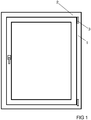
- FIG. 1 shows a window with a frame 1, a wing 2 and a bearing according to the invention 3.
- the window can be displaced by means of a handle, for example in the usual rotary or tilt-and-turn motion.
- the bearing can also be used for other components, such as French doors or doors, and can be used anywhere along the axis of rotation of the wing.
- the bearing described is used as the upper wing bearing, wherein the tilting movement is made possible by an upper opening shears and at least one lower tilting bearing.
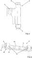
- FIG. 2 It consists of a wing-side fitting part 4 and a frame-side bearing block 6. Both parts are rotatably connected to each other via a bearing pin 5 connected.
- FIG. 3 It consists of a base plate 7 and two bearing lugs 8, wherein the settlement of the starting material from the base plate 7 with two protruding tabs, wherein the bearing eyes 8 from the protruding from the base plate 7 tabs by forming, such as rollers or Bending, were made.
- the bearing eyes 8 in this case have an integrally connected to the base plate 7 first end 23 and a second end 24, which serves to fix the bearing eye shape after the preparation of this.
- the bearing lugs 8 each comprise a detent sleeve 9, in which the later insertable bearing pin 5 can be fixed.
- the base plate 7 has a bevelled edge 10, which faces the wing 2 in the assembled state, and a web 11 on the opposite longitudinal side. Both run between the bearing eyes 8.
- the web 11 is also formed during sheet metal forming of the one-piece sheet and increases the stability of the bearing block 6. Furthermore, it forms a lateral conclusion of the bearing pin holder.
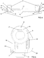
- FIG. 4 shows the bearing block 6 according to the invention FIG. 3 in the side view.
- two pins 13 can be seen in this view, which protrude at the bottom of the base plate 7 in the direction of the frame 1. These can be used for preliminary alignment and fixation of the bearing block 6 on the frame 1 and thus allow easy mounting of the bearing 3 and a higher positional stability of the bearing block 6 after assembly.
- this view is aligned with the positive connection, so that it can be seen that at the second ends 24 of the bearing eyes 8, an extension 14 is mounted, which engages in a recess 15 of the base plate 7.
- the recess 15 is stepped, so that it has an enlarged receiving area 16 for a final mushroom-like Material extension, such as a preformed or produced by subsequent forming head 20 or compression, and a defined receiving area for the extension 14 itself gives. Furthermore, it can be seen that the locking sleeve 9 is largely enclosed by the bearing eye 8 and only a head portion of the locking sleeve 9 remains exposed.
- FIG. 5 shows the bearing eye 8 according to the invention in an enlarged view along the axis of rotation of the bearing pin 5.
- the bearing eye 8 is formed on its inner side inter alia of a straight portion 18 and a radius 19.
- the first end 23 and the second end 24 of the bearing eye 8 are shown, which connect this with the base plate 7.
- the outer contour 22 of the locking sleeve 9 is adapted to this shape of the bearing eye 8, so that an unwanted rotation of the locking sleeve 9 is excluded.
- the head of the locking sleeve 9, the inner side 17 of the bearing eye 8 overlaps and thus engages behind. This ensures an additional hold of the locking sleeve. 9
- FIG. 6 is a bearing eye 8 according to the invention embodiment in an enlarged side view.
- the fixation of the second end 24 of the bearing eye 8 is implemented in this embodiment by means of a rectangular head 20 which is formed on the extension 14. This engages behind the deformation of the sheet metal piece in the extended receiving portion 16 of the recess 15, the base plate 7 and thus ensures the closure of the bearing eye.
- FIG. 7 A second embodiment of the positive connection is in FIG. 7 shown. After the bearing eye 8 is bent by the first deformation, it is fixed by means of a further deformation of the base plate 7. Thus, a complete positive connection of the connection between the base plate 7 and the second end 24 of the bearing eye 8 is achieved.
- FIG. 8 and FIG. 9 show the backs of the in FIG. 6 and FIG. 7 illustrated embodiments of the bearing block 6. It is the form-fitting connections of the second end 24 of the bearing eye 8 with the base plate 7 by means of the extension 14 shown.
- FIG. 8 is the embodiment that makes the connection by means of behind, shown and the rectangular head 20 of the extension 14 can be seen. This is introduced into the correspondingly shaped extended receiving area 16 of the base plate 7. This is possible with a preformed rectangular head 20 by pivoting from the opening on the longitudinal side of the base plate 7.
- FIG. 9 the variant is shown by deformation. Here was a rivet 21 in one arranged after the forming process, the illustrated complete positive engagement for connecting the second end 24 of the bearing eye 8 with the base plate 7.
- the extended receiving portion 16 is circular in this case and arranged so that a circular opening on the longitudinal edge of the base plate is present, which closes flush with the rivet 21.
- the circular opening on the longitudinal edge of the base plate 7 is narrower than the diameter of the circular extended receiving area 16.
Landscapes
- Engineering & Computer Science (AREA)
- Mechanical Engineering (AREA)
- Hinges (AREA)
- Wing Frames And Configurations (AREA)
- Connection Of Plates (AREA)
Abstract
Description
- Die Erfindung betrifft ein Lager für einen gegen einen Rahmen schwenkbaren Flügel mit einem rahmenseitigen Lagerbock und mit einem flügelseitigen, gegenüber dem rahmenseitigen Lagerbock verdrehbaren Beschlagteil und mit einem in einer Drehachse der Beschlagteile liegenden Lagerbolzen, wobei der rahmenseitige Lagerbock aus einer Grundplatte und mindestens einem Lagerauge, zur Aufnahme des Lagerbolzens, besteht, wobei das Lagerauge durch Umformung einer einstückig an der Grundplatte angeordneten Lasche gebildet ist und das Lagerauge ein an der Grundplatte festes erstes Ende sowie ein zweites Ende aufweist und das Lagerauge zur sicheren Halterung des Lagerbolzens eine Rasthülse umschließt.
- Ein ähnliches Lager ist bereits aus der
DE 1 972 819 U bekannt. Hierbei ist das Lager komplett aus einem Blechstück geformt und weist eine durchgängige Rolle zum Umschluss des Lagerbolzens auf. Kennzeichnend für die beschriebene Erfindung ist, dass die Form der Rolle während der Montage des Fensters angepasst und somit auf die Gegebenheiten angepasst werden kann. Hierzu kann die Krümmung der Rolle mithilfe eines entsprechenden Werkzeugs eingestellt werden. Nachteilig an dieser Erfindung ist jedoch, dass die Rolle nicht an der Grundplatte selbst fixiert wird, sondern im Rahmen der Montage lediglich durch eine elastische Hülse verschlossen wird, was zu Einbußen in der Stabilität des Lagers führt. - Heutzutage übliche Zinkdruckgusslager, oder zumindest Zinkdruckguss-Stahlverbund-Lager, welche eine geschlossene Lagerung für den Lagerbolzen bieten und eine einstückige Ausbildung des Lagers zulassen, können aufgrund des verwendeten Materials ebenfalls eine geringere Stabilität aufweisen.
- Der Erfindung liegt das Problem zugrunde ein Lager der eingangs erwähnten Art so weiterzubilden, dass es eine hohe Stabilität und Betätigungssicherheit aufweist.
- Das Problem wird erfindungsgemäß dadurch gelöst, dass das zweite Ende des Lagerauges formschlüssig mit der Grundplatte verbunden ist. Durch diese Gestaltung weist das Lager, welches den Lagerbolzen aufnimmt und somit das Flügelgewicht am Rahmen hält, eine erhöhte Stabilität gegenüber einseitig offenen Lagern auf. Die Stabilität gegenüber herkömmlichen Zinkdruckgusslagern kann durch Verwendung von beispielsweise Stahlblech zur Umformung erhöht werden. Das Lager ist üblicherweise als Drehlager ausgeführt und kann nahe der oberen Ecke, nahe der unteren Ecke oder dazwischen entlang der Drehachse eines zumindest drehbaren Flügels eines Fensters oder einer Tür angeordnet sein.
- Eine vorteilhafte Weiterbildung der Erfindung sieht vor, dass das zweite Ende des Lagerauges einen Fortsatz aufweist, der in eine zur Längsseite des Lagerbocks offene Ausnehmung der Grundplatte eingreift. Hierdurch wird durch einfache Weise das Biegen des Lagerauges in einem Arbeitsgang erleichtert.
- Gemäß einer vorteilhaften Weiterbildung der Erfindung wird die Aufnahme des Fortsatzes optimiert, wenn die Ausnehmung stufig ausgebildet ist, mit einem erweiterten Aufnahmebereich in Richtung der dem Rahmen zugewandten Unterseite der Grundplatte. Dadurch wird Raum geschaffen für Materialüberstände und als Toleranzausgleich.
- Eine vorteilhafte Weiterbildung der Erfindung sieht vor, dass der Fortsatz an seinem freien Ende einen verbreiterten Kopf aufweist, welcher in den erweiterten Aufnahmebereich der Ausnehmung der Grundplatte angeordnet werden kann und die Grundplatte somit hintergreift. Hierdurch wird auf einfache Art ein Formschluss zwischen dem zweiten Ende des Lagerauges und der Grundplatte erzeugt. Somit wird das zweite Ende an der Grundplatte fixiert und kann nicht von der Grundplatte weg aus der Ausnehmung herausgezogen werden.
- Eine Verbindung kann gemäß einer vorteilhaften Weiterbildung der Erfindung auch dadurch erreicht werden, dass der Kopf in dem stufigen, erweiterten Aufnahmebereich der Ausnehmung der Grundplatte mittels Umformen gebildet wird. Durch diese Ausführung kann der Fortsatz zunächst sehr schmal ausgeführt werden, so dass er direkt in Richtung der Grundplatte in die Ausnehmung eingeführt werden kann und nicht von der Seite eingeschwenkt werden muss. Durch das anschließende Umformen, bevorzugt nach dem Einführen des Fortsatzes in die Ausnehmung, kann ein zur Ausnehmung spielfreier Kopf im erweiterten Aufnahmebereich der Ausnehmung erzeugt werden. Dies verbessert den spielfreien Formschluss und damit das Lagerspiel. Es ist bevorzugt maximal so viel umformbares Material vorhanden, wie in den erweiterten Aufnahmebereich der Ausnehmung aufgenommen werden kann, um eine weitgehend ebene Auflagefläche der Grundplatte beizubehalten.
- Eine vollständig formschlüssige Verbindung ist gemäß einer vorteilhaften Weiterbildung der Erfindung dann besonders sicher gestaltet, wenn der erweiterte Aufnahmebereich als Kreis ausgebildet ist, wobei die Mitte des erweiterten Aufnahmebereichs einen Abstand kleiner ihrem Radius zur Längskante der Grundplatte aufweist, so dass eine Kreisöffnung an der Längsseite ausgebildet ist. Hierdurch wird eine stabilere Verbindung des zweiten Endes des Lagerauges mit der Grundplatte und somit ein erhöhter Widerstand gegen eine ungewollte Verformung des Lagerauges gewährleistet. Des Weiteren gestaltet sich das Einschwenken des Fortsatzes einfacher und ein formschlüssiger Halt gegen sein Zurückschwenken wird gewährleistet, da der Kreisdurchmesser größer ist als die Kreisöffnung an der Längskante der Grundplatte. Es wird hierbei idealerweise ein runder Fortsatz verwendet, der einen Durchmesser kleiner der Breite der an der Längsseite des Lagerbocks offene Ausnehmung der Grundplatte aufweist und so lang ist, dass nach einem Umformvorgang des Fortsatzes der erweiterte Aufnahmebereich zumindest teilweise ausgefüllt ist.
- Die Rasthülsen werden nach einer anderen vorteilhaften Weiterbildung der Erfindung gegen ungewolltes Verdrehen gesichert, wenn der Querschnitt des Lagerauges auf der Innenseite zumindest eine Gerade und einen Radius aufweist und die Außenkontur der Rasthülse an die Form des Lagerauges angepasst ist.
- Gemäß einer vorteilhaften Weiterbildung der Erfindung ist das Lager so ausgeführt, dass das Lagerauge die Rasthülse größtenteils umschließt und die Rasthülse das Lagerauge zumindest von einer Seite hintergreift. Hierdurch kann die Rasthülse gegen ein Verschieben in Richtung der Drehachse des Lagerbolzens gesichert werden.
- Das Lager ist nach einer vorteilhaften Weiterbildung verschleißarm, wenn bei einer Ausführung mit mindestens zwei Lageraugen die Grundplatte auf einer Längsseite eine längs verlaufende Schrägkante aufweist, die zwischen den Lageraugen verläuft und auf der Seite der formschlüssigen Verbindung angeordnet ist. Das Lager wird vorzugsweise mit der Schrägkante in Richtung Flügel angeordnet und somit sichert diese ein reibungsloses Drehen des Flügels in die Geschlossenstellung und schafft Raum für die stabile Ausgestaltung des flügelseitigen Beschlagteils, was auf Dauer für weniger Verschleiß und eine leichtere Bedienung sorgt.
- Das Lager lässt sich gemäß einer weiteren vorteilhaften Weiterbildung der Erfindung noch stabiler ausführen, wenn auf der der Schrägkante gegenüberliegenden Längsseite des Lagers ein Steg angeordnet ist, der zwischen den Lageraugen verläuft und während der Umformung der Lageraugen einstückig mit geformt wird.
- Die Montage des Lagers lässt sich gemäß einer anderen vorteilhaften Weiterbildung der Erfindung verbessern, wenn die Grundplatte an ihrer dem Rahmen zugewandten Unterseite mindestens einen Zapfen ausweist. Hierdurch lässt sich die Grundplatte in einer im Rahmen eingebrachten Ausnehmung, welche die Kontur des Zapfens aufweist, fixieren. Dadurch bietet der Zapfen einen verlässlichen Schutz gegen ungewolltes Verdrehen oder Verschieben des Lagers während der Montage und im montierten Zustand.
- Das Lager ist gemäß einer anderen vorteilhaften Weiterbildung so gestaltet, dass die Grundplatte Verlängerungen aufweist, die über die Außenseiten der Lageraugen hinausgehen. Somit sind mehr Möglichkeiten zur Befestigung und zur Handhabe des Lagers gegeben.
- Die Erfindung lässt zahlreiche Ausführungsformen zu. Zur weiteren Verdeutlichung ihres Grundprinzips ist eine davon in der Zeichnung dargestellt und wird nachfolgend beschrieben. Diese zeigt in
- Fig. 1
- Eine allgemeine Darstellung eines Fensters mit einer erfindungsgemäßen Lageranordnung.
- Fig. 2
- Darstellung eines erfindungsgemäßen Lagers, umfassend einen rahmenseitigen Lagerbock und ein flügelseitiges Beschlagteil.
- Fig. 3
- Ein erfindungsgemäßer Lagerbock in perspektivischer Seitenansicht.
- Fig. 4
- Der Lagerbock aus
Fig. 3 in einer Seitenansicht. - Fig. 5
- Darstellung eines Lagerauges in Richtung der Drehachse eines Lagerbolzens.
- Fig. 6
- Eine vergrößerte Darstellung eines Lagerauges auf der Seite der formschlüssigen Verbindung mit einem die Grundplatte hintergreifenden Kopf.
- Fig. 7
- Eine vergrößerte Darstellung eines Lagerauges auf der Seite der formschlüssigen Verbindung mit einer umgeformten Verbindung.
- Fig. 8
- Eine vergrößerte Darstellung der Rückseite des Lagerbocks mit einem die Grundplatte hintergreifenden Kopf.
- Fig. 9
- Eine vergrößerte Darstellung der Rückseite des Lagerbocks mit einer umgeformten Verbindung.
-
Figur 1 zeigt ein Fenster mit einem Rahmen 1, einem Flügel 2 und einem erfindungsgemäßen Lager 3. Das Fenster kann mittels einer Handhabe beispielsweise in gewohnter Dreh- oder Dreh-Kipp-Bewegung verlagert werden. Das Lager kann auch für andere Bauteile, wie Fenstertüren oder Türen, verwendet werden und ist überall entlang der Drehachse des Flügels einsetzbar. Bei Dreh-Kipp-Fenstern ist das beschriebene Lager als oberes Flügellager einsetzbar, wobei die Kippbewegung durch eine obere Öffnungsschere und zumindest ein unteres Kipplager ermöglicht wird. -
Figur 2 zeigt ein erfindungsgemäßes Lager 3. Es besteht aus einem flügelseitigen Beschlagteil 4 und einem rahmenseitigen Lagerbock 6. Beide Teile sind über einen Lagerbolzen 5 miteinander drehgelagert Verbunden. -
Figur 3 zeigt einen Lagerbock 6. Er besteht aus einer Grundplatte 7 und zwei Lageraugen 8, wobei die Abwicklung des Vormaterials aus der Grundplatte 7 mit zwei abstehenden Laschen besteht, wobei die Lageraugen 8 aus den von der Grundplatte 7 abstehenden Laschen durch Umformung, wie beispielsweise Walzen oder Biegen, hergestellt wurden. Die Lageraugen 8 weisen dabei ein einstückig mit der Grundplatte 7 verbundenes erstes Ende 23 sowie ein zweites Ende 24 auf, welches zur Fixierung der Lageraugenform nach der Herstellung dieser dient. Die Lageraugen 8 umfassen jeweils eine Rasthülse 9, in welchen der später einführbare Lagerbolzen 5 fixiert werden kann. Weiterhin weist die Grundplatte 7 eine Schrägkante 10, die im montierten Zustand dem Flügel 2 zugewandt ist, und einen Steg 11 auf der gegenüberliegenden Längsseite auf. Beide verlaufen zwischen den Lageraugen 8. Der Steg 11 wird ebenfalls während der Blechumformung aus dem einstückigen Blech gebildet und erhöht die Stabilität des Lagerbocks 6. Des Weiteren bildet er einen seitlichen Abschluss der Lagerbolzenaufnahme. -
Figur 4 zeigt den erfindungsgemäßen Lagerbock 6 ausFigur 3 in der Seitenansicht. Neben den bereits genannten technischen Merkmalen sind in dieser Ansicht zwei Zapfen 13 zu erkennen, welche an der Unterseite der Grundplatte 7 in Richtung des Rahmens 1 hervorstehen. Diese können zur vorläufigen Ausrichtung und Fixierung des Lagerbocks 6 am Rahmen 1 verwendet werden und gestatten somit eine einfache Montierung des Lagers 3 sowie eine höhere Lagestabilität des Lagerbocks 6 nach der Montage. Zudem ist diese Ansicht auf die formschlüssige Verbindung ausgerichtet, sodass erkennbar ist, dass an den zweiten Enden 24 der Lageraugen 8 ein Fortsatz 14 angebracht ist, welcher in eine Ausnehmung 15 der Grundplatte 7 greift. Die Ausnehmung 15 ist stufig ausgebildet, sodass es einen erweiterten Aufnahmebereich 16 für einen abschließenden pilzkopfartigen Materialfortsatz, wie beispielsweise einen vorgeformten oder einen durch nachträgliches Umformen hergestellten Kopf 20 oder eine Stauchung, und einen definierten Aufnahmebereich für den Fortsatz 14 selbst gibt. Des Weiteren ist zu erkennen, dass die Rasthülse 9 weitestgehend von dem Lagerauge 8 umschlossen wird und lediglich ein Kopfteil der Rasthülse 9 freiliegend bleibt. -
Figur 5 zeigt das erfindungsgemäße Lagerauge 8 in vergrößerter Darstellung entlang der Drehachse des Lagerbolzens 5. Auch hier ist wieder die als Zapfen 13 ausgeführte Erhebung an der Unterseite der Grundplatte 7 zu erkennen. Weiterhin ist erkennbar, dass das Lagerauge 8 an seiner Innenseite unter anderem aus einem geraden Abschnitt 18 und einem Radius 19 gebildet wird. Des Weiteren sind das erste Ende 23 und das zweite Ende 24 des Lagerauges 8 gezeigt, welche dieses mit der Grundplatte 7 verbinden. Die Außenkontur 22 der Rasthülse 9 ist an diese Form des Lagerauges 8 angepasst, sodass ein ungewolltes verdrehen der Rasthülse 9 ausgeschlossen ist. Weiterhin ist zu erkennen, dass der Kopf der Rasthülse 9 die Innenseite 17 des Lagerauges 8 überlappt und es somit hintergreift. Dies gewährleistet einen zusätzlichen Halt der Rasthülse 9 - In
Figur 6 ist ein Lagerauge 8 erfindungsgemäßer Ausführung in vergrößerter Seitenansicht zu sehen. Die Fixierung des zweiten Endes 24 des Lagerauges 8 wird in diesem Ausführungsbeispiel mittels eines rechteckigen Kopfes 20, welcher an dem Fortsatz 14 ausgebildet ist, umgesetzt. Dieser hintergreift nach der Umformung des Blechstücks in dem erweiterten Aufnahmebereich 16 der Ausnehmung 15 die Grundplatte 7 und sorgt so für den Verschluss des Lagerauges 8. - Eine zweite Ausführungsform der formschlüssigen Verbindung ist in
Figur 7 gezeigt. Nachdem das Lagerauge 8 durch die erste Umformung gebogen ist, wird es mittels einer weiteren Umformung an der Grundplatte 7 fixiert. Somit wird ein kompletter Formschluss der Verbindung zwischen Grundplatte 7 und dem zweiten Ende 24 des Lagerauges 8 erreicht. - Die
Figur 8 und Figur 9 zeigen die Rückseiten der inFigur 6 und Figur 7 dargestellten erfindungsgemäßen Ausführungsformen des Lagerbocks 6. Es sind die formschlüssigen Verbindungen des zweiten Endes 24 des Lagerauges 8 mit der Grundplatte 7 mittels des Fortsatzes 14 gezeigt. InFigur 8 ist die Ausführung, welche die Verbindung mittels hintergreifen herstellt, gezeigt und der rechteckige Kopf 20 des Fortsatzes 14 ist zu erkennen. Dieser ist in den entsprechend geformten erweiterten Aufnahmebereich 16 der Grundplatte 7 eingeführt. Dies ist bei vorgeformtem rechteckigen Kopf 20 durch einschwenken von der Öffnung an der Längsseite der Grundplatte 7 möglich. InFigur 9 ist die Variante mittels Verformung gezeigt. Hierbei wurde ein Niet 21 in einem formangepassten erweiterten Aufnahmebereich 16 angeordnet und bildet nach dem Umformvorgang den dargestellten vollständigen Formschluss zur Verbindung des zweiten Endes 24 des Lagerauges 8 mit der Grundplatte 7. Der erweiterte Aufnahmebereich 16 ist in diesem Fall kreisförmig ausgebildet und so angeordnet, dass eine Kreisöffnung an der Längskante der Grundplatte vorhanden ist, welche bündig mit dem Niet 21 schließt. Die Kreisöffnung an der Längskante der Grundplatte 7 ist schmaler als der Durchmesser des kreisförmigen erweiterten Aufnahmebereichs 16.
Claims (12)
- Lager (3) für einen gegen einen Rahmen (1) schwenkbaren Flügel (2) mit einem rahmenseitigen Lagerbock (6) und mit einem flügelseitigen, gegenüber dem rahmenseitigen Lagerbock (6) verdrehbaren Beschlagteil (4) und mit einem in einer Drehachse der Beschlagteile (4, 6) liegenden Lagerbolzen (5), wobei der rahmenseitige Lagerbock (6) aus einer Grundplatte (7) und mindestens einem Lagerauge (8) zur Aufnahme des Lagerbolzens (5) besteht, wobei das Lagerauge (8) durch Umformung einer einstückig an der Grundplatte (7) angeordneten Lasche gebildet ist und das Lagerauge (8) ein an der Grundplatte (7) festes erstes Ende (23) sowie ein zweites Ende (24) aufweist und das Lagerauge (8) zur sicheren Halterung des Lagerbolzens eine Rasthülse (9) umschließt, dadurch gekennzeichnet, dass das zweite Ende (24) des Lagerauges (8) formschlüssig mit der Grundplatte (7) verbunden ist.
- Lager (3) nach Anspruch 1, dadurch gekennzeichnet, dass das zweite Ende (24) des Lagerauges (8) einen Fortsatz (14) aufweist, der in eine zur Längsseite des Lagerbocks (6) offene Ausnehmung (15) der Grundplatte (7) eingreift.
- Lager (3) nach Anspruch 2, dadurch gekennzeichnet, dass die Ausnehmung (15) stufig ausgebildet ist, mit einem erweiterten Aufnahmebereich (16) in Richtung der dem Rahmen (1) zugewandten Unterseite der Grundplatte (7).
- Lager (3) nach Anspruch 3, dadurch gekennzeichnet, dass der Fortsatz (14) an seinem freien Ende einen verbreiterten Kopf (20) aufweist, welcher in den erweiterten Aufnahmebereich (16) der Ausnehmung (15) der Grundplatte (7) angeordnet werden kann und die Grundplatte (7) somit hintergreift.
- Lager (3) nach Anspruch 3, dadurch gekennzeichnet, dass der Kopf (20) in dem stufigen, erweiterten Aufnahmebereich (16) der Ausnehmung (15) der Grundplatte (7) mittels Umformen gebildet wird.
- Lager (3) nach einem der Ansprüche 2 bis 5, dadurch gekennzeichnet, dass der erweiterte Aufnahmebereich (16) als Kreis ausgebildet ist, wobei die Mitte des erweiterten Aufnahmebereichs (16) einen Abstand kleiner ihrem Radius zur Längskante der Grundplatte (7) aufweist, so dass eine Kreisöffnung an der Längsseite ausgebildet ist.
- Lager (3) nach einem der Ansprüche 1 bis 6, dadurch gekennzeichnet, dass der Querschnitt des Lagerauges (8) auf der Innenseite (17) zumindest eine Gerade (18) und einen Radius (19) aufweist und die Außenkontur (22) der Rasthülse (9) an die Form des Lagerauges angepasst ist.
- Lager (3) nach einem der Ansprüche 1 bis 7, dadurch gekennzeichnet, dass das Lagerauge (8) die Rasthülse (9) größtenteils umschließt und die Rasthülse (9) das Lagerauge (8) zumindest von einer Seite hintergreift.
- Lager (3) nach einem der Ansprüche 1 bis 8, dadurch gekennzeichnet, dass bei einer Ausführung mit mindestens zwei Lageraugen (8) die Grundplatte (7) auf einer Längsseite eine längs verlaufende Schrägkante (10) aufweist, die zwischen dein Lageraugen (8) verläuft und auf der Seite der formschlüssigen Verbindung angeordnet ist.
- Lager (3) nach Anspruch 9, dadurch gekennzeichnet, dass auf der der Schrägkante (10) gegenüberliegenden Längsseite des Lagers (3) ein Steg (6) angeordnet ist, der zwischen den Lageraugen (8) verläuft und während der Umformung der Lageraugen (8) einstückig mit geformt wird.
- Lager (3) nach einem der Ansprüche 1 bis 8, dadurch gekennzeichnet, dass die Grundplatte (7) an ihrer dem Rahmen (1) zugewandten Unterseite mindestens einen Zapfen (13) ausweist.
- Lager (3) nach einem der Ansprüche 1 bis 9, dadurch gekennzeichnet, dass die Grundplatte (7) Verlängerungen (12) aufweist, die über die Außenseiten der Lageraugen (8) hinausgehen.
Priority Applications (3)
| Application Number | Priority Date | Filing Date | Title |
|---|---|---|---|
| SI201930016T SI3543444T1 (sl) | 2018-03-20 | 2019-03-13 | Tečaj za vgradno napravo okna |
| PL19162520T PL3543444T3 (pl) | 2018-03-20 | 2019-03-13 | Łożysko do układu zawiasowego okna |
| HRP20202029TT HRP20202029T1 (hr) | 2018-03-20 | 2020-12-18 | Ležaj za uređaj za ugradnju prozora |
Applications Claiming Priority (1)
| Application Number | Priority Date | Filing Date | Title |
|---|---|---|---|
| DE102018204217.9A DE102018204217A1 (de) | 2018-03-20 | 2018-03-20 | Lager für eine Beschlaganordnung eines Fensters |
Publications (2)
| Publication Number | Publication Date |
|---|---|
| EP3543444A1 true EP3543444A1 (de) | 2019-09-25 |
| EP3543444B1 EP3543444B1 (de) | 2020-10-28 |
Family
ID=65801987
Family Applications (1)
| Application Number | Title | Priority Date | Filing Date |
|---|---|---|---|
| EP19162520.1A Active EP3543444B1 (de) | 2018-03-20 | 2019-03-13 | Lager für eine beschlaganordnung eines fensters |
Country Status (8)
| Country | Link |
|---|---|
| EP (1) | EP3543444B1 (de) |
| DE (1) | DE102018204217A1 (de) |
| DK (1) | DK3543444T3 (de) |
| ES (1) | ES2835999T3 (de) |
| HR (1) | HRP20202029T1 (de) |
| HU (1) | HUE052312T2 (de) |
| PL (1) | PL3543444T3 (de) |
| SI (1) | SI3543444T1 (de) |
Citations (5)
| Publication number | Priority date | Publication date | Assignee | Title |
|---|---|---|---|---|
| DE1972819U (de) | 1967-09-09 | 1967-11-16 | Wilhelm Frank G M B H | Aus blech gebogene bandhuelse fuer fenster, tueren od. dgl. |
| DE7612224U1 (de) * | 1976-04-17 | 1976-08-26 | Hagri, Hans Grimberg, 4307 Kettwig | Scharnier |
| DE9308669U1 (de) * | 1993-06-10 | 1994-10-27 | Gretsch-Unitas GmbH Baubeschläge, 71254 Ditzingen | Beschlagteil für die wenigstens drehbare Lagerung eines Flügels, eines Fensters, einer Tür o.dgl. |
| DE19528656C1 (de) * | 1995-08-04 | 1996-08-14 | Aubi Baubeschlaege Gmbh | Drehlagerbock für Dreh- oder Drehkippfenster, -türen oder dergleichen |
| US20090307871A1 (en) * | 2008-06-11 | 2009-12-17 | Protorsion Hinge Co., Ltd. | Hinge structure having a knuckle with anti-unfolding property |
-
2018
- 2018-03-20 DE DE102018204217.9A patent/DE102018204217A1/de not_active Withdrawn
-
2019
- 2019-03-13 EP EP19162520.1A patent/EP3543444B1/de active Active
- 2019-03-13 HU HUE19162520A patent/HUE052312T2/hu unknown
- 2019-03-13 DK DK19162520.1T patent/DK3543444T3/da active
- 2019-03-13 SI SI201930016T patent/SI3543444T1/sl unknown
- 2019-03-13 ES ES19162520T patent/ES2835999T3/es active Active
- 2019-03-13 PL PL19162520T patent/PL3543444T3/pl unknown
-
2020
- 2020-12-18 HR HRP20202029TT patent/HRP20202029T1/hr unknown
Patent Citations (5)
| Publication number | Priority date | Publication date | Assignee | Title |
|---|---|---|---|---|
| DE1972819U (de) | 1967-09-09 | 1967-11-16 | Wilhelm Frank G M B H | Aus blech gebogene bandhuelse fuer fenster, tueren od. dgl. |
| DE7612224U1 (de) * | 1976-04-17 | 1976-08-26 | Hagri, Hans Grimberg, 4307 Kettwig | Scharnier |
| DE9308669U1 (de) * | 1993-06-10 | 1994-10-27 | Gretsch-Unitas GmbH Baubeschläge, 71254 Ditzingen | Beschlagteil für die wenigstens drehbare Lagerung eines Flügels, eines Fensters, einer Tür o.dgl. |
| DE19528656C1 (de) * | 1995-08-04 | 1996-08-14 | Aubi Baubeschlaege Gmbh | Drehlagerbock für Dreh- oder Drehkippfenster, -türen oder dergleichen |
| US20090307871A1 (en) * | 2008-06-11 | 2009-12-17 | Protorsion Hinge Co., Ltd. | Hinge structure having a knuckle with anti-unfolding property |
Also Published As
| Publication number | Publication date |
|---|---|
| DK3543444T3 (da) | 2020-12-21 |
| PL3543444T3 (pl) | 2021-03-08 |
| DE102018204217A1 (de) | 2019-09-26 |
| HUE052312T2 (hu) | 2021-04-28 |
| ES2835999T3 (es) | 2021-06-23 |
| HRP20202029T1 (hr) | 2021-02-19 |
| EP3543444B1 (de) | 2020-10-28 |
| SI3543444T1 (sl) | 2021-01-29 |
Similar Documents
| Publication | Publication Date | Title |
|---|---|---|
| EP2476834B1 (de) | Türband für eine verdeckte Anordnung zwischen Türrahmen und Türflügel | |
| DE9306387U1 (de) | Federscharnier für Brille | |
| EP1367203B1 (de) | Scharnier | |
| DE102012213772B4 (de) | Federklemme für gabelförmige Schlitten in flexiblen Scharnieren sowie ein entsprechendes flexibles Scharnier | |
| EP2546438B1 (de) | Zur verschieblichen Montage in einer einen Hinterschnitt aufweisenden Beschlagnut vorgesehenes Beschlagteil | |
| DE19951440A1 (de) | Wischarm für ein Fahrzeug | |
| DE102020106690B3 (de) | Türband für Gebäudetüren | |
| EP3175068B1 (de) | Beschlaganordnung | |
| DE19913313A1 (de) | Scharnier | |
| EP3543444A1 (de) | Lager für eine beschlaganordnung eines fensters | |
| DE3786280T2 (de) | Federscharnier für Brillen. | |
| DE69704809T2 (de) | Türfeststeller für Kraftwagentüren | |
| DE102005012419B4 (de) | Lagerbügel eines Außengriffes einer Fahrzeugtür für Kraftfahrzeuge | |
| DE1225988B (de) | Ausstellvorrichtung fuer Drehkippfenster, -tueren od. dgl. | |
| DE2342641C3 (de) | Türangelanordnung | |
| DE19820742A1 (de) | Beschlagteil eines an einem Rahmen anzubringenden Beschlagsystems, beispielsweise eines Fenster- oder Türbeschlags | |
| DE19854718A1 (de) | Fenster- oder Türdrehkippbeschlag | |
| DE19528656C1 (de) | Drehlagerbock für Dreh- oder Drehkippfenster, -türen oder dergleichen | |
| EP2045426B1 (de) | Flügelbefestigungsanordnung eines Drehlagers | |
| EP2374973B1 (de) | Band für Türen, Fenster oder dergleichen | |
| DE202025004160U1 (de) | Türband und Gebäudetür | |
| EP3382130B1 (de) | Verriegelungseinheit und fenster oder türe mit einer solchen verriegelungseinheit | |
| DE3432160C2 (de) | Kipptor | |
| DE9210056U1 (de) | Federscharnier für Brillen | |
| DE2129252A1 (de) | Scharnier |
Legal Events
| Date | Code | Title | Description |
|---|---|---|---|
| PUAI | Public reference made under article 153(3) epc to a published international application that has entered the european phase |
Free format text: ORIGINAL CODE: 0009012 |
|
| STAA | Information on the status of an ep patent application or granted ep patent |
Free format text: STATUS: THE APPLICATION HAS BEEN PUBLISHED |
|
| AK | Designated contracting states |
Kind code of ref document: A1 Designated state(s): AL AT BE BG CH CY CZ DE DK EE ES FI FR GB GR HR HU IE IS IT LI LT LU LV MC MK MT NL NO PL PT RO RS SE SI SK SM TR |
|
| AX | Request for extension of the european patent |
Extension state: BA ME |
|
| STAA | Information on the status of an ep patent application or granted ep patent |
Free format text: STATUS: REQUEST FOR EXAMINATION WAS MADE |
|
| 17P | Request for examination filed |
Effective date: 20200226 |
|
| RBV | Designated contracting states (corrected) |
Designated state(s): AL AT BE BG CH CY CZ DE DK EE ES FI FR GB GR HR HU IE IS IT LI LT LU LV MC MK MT NL NO PL PT RO RS SE SI SK SM TR |
|
| GRAP | Despatch of communication of intention to grant a patent |
Free format text: ORIGINAL CODE: EPIDOSNIGR1 |
|
| STAA | Information on the status of an ep patent application or granted ep patent |
Free format text: STATUS: GRANT OF PATENT IS INTENDED |
|
| INTG | Intention to grant announced |
Effective date: 20200616 |
|
| GRAS | Grant fee paid |
Free format text: ORIGINAL CODE: EPIDOSNIGR3 |
|
| GRAA | (expected) grant |
Free format text: ORIGINAL CODE: 0009210 |
|
| STAA | Information on the status of an ep patent application or granted ep patent |
Free format text: STATUS: THE PATENT HAS BEEN GRANTED |
|
| AK | Designated contracting states |
Kind code of ref document: B1 Designated state(s): AL AT BE BG CH CY CZ DE DK EE ES FI FR GB GR HR HU IE IS IT LI LT LU LV MC MK MT NL NO PL PT RO RS SE SI SK SM TR |
|
| REG | Reference to a national code |
Ref country code: GB Ref legal event code: FG4D Free format text: NOT ENGLISH |
|
| REG | Reference to a national code |
Ref country code: CH Ref legal event code: EP |
|
| REG | Reference to a national code |
Ref country code: DE Ref legal event code: R096 Ref document number: 502019000333 Country of ref document: DE |
|
| REG | Reference to a national code |
Ref country code: AT Ref legal event code: REF Ref document number: 1328402 Country of ref document: AT Kind code of ref document: T Effective date: 20201115 |
|
| REG | Reference to a national code |
Ref country code: IE Ref legal event code: FG4D Free format text: LANGUAGE OF EP DOCUMENT: GERMAN |
|
| REG | Reference to a national code |
Ref country code: HR Ref legal event code: TUEP Ref document number: P20202029 Country of ref document: HR |
|
| REG | Reference to a national code |
Ref country code: DK Ref legal event code: T3 Effective date: 20201218 Ref country code: RO Ref legal event code: EPE |
|
| REG | Reference to a national code |
Ref country code: NL Ref legal event code: FP |
|
| REG | Reference to a national code |
Ref country code: SE Ref legal event code: TRGR |
|
| REG | Reference to a national code |
Ref country code: SK Ref legal event code: T3 Ref document number: E 36109 Country of ref document: SK |
|
| REG | Reference to a national code |
Ref country code: HR Ref legal event code: T1PR Ref document number: P20202029 Country of ref document: HR |
|
| REG | Reference to a national code |
Ref country code: HR Ref legal event code: ODRP Ref document number: P20202029 Country of ref document: HR Payment date: 20210223 Year of fee payment: 3 |
|
| REG | Reference to a national code |
Ref country code: HU Ref legal event code: AG4A Ref document number: E052312 Country of ref document: HU |
|
| PG25 | Lapsed in a contracting state [announced via postgrant information from national office to epo] |
Ref country code: GR Free format text: LAPSE BECAUSE OF FAILURE TO SUBMIT A TRANSLATION OF THE DESCRIPTION OR TO PAY THE FEE WITHIN THE PRESCRIBED TIME-LIMIT Effective date: 20210129 Ref country code: NO Free format text: LAPSE BECAUSE OF FAILURE TO SUBMIT A TRANSLATION OF THE DESCRIPTION OR TO PAY THE FEE WITHIN THE PRESCRIBED TIME-LIMIT Effective date: 20210128 Ref country code: PT Free format text: LAPSE BECAUSE OF FAILURE TO SUBMIT A TRANSLATION OF THE DESCRIPTION OR TO PAY THE FEE WITHIN THE PRESCRIBED TIME-LIMIT Effective date: 20210301 Ref country code: RS Free format text: LAPSE BECAUSE OF FAILURE TO SUBMIT A TRANSLATION OF THE DESCRIPTION OR TO PAY THE FEE WITHIN THE PRESCRIBED TIME-LIMIT Effective date: 20201028 Ref country code: FI Free format text: LAPSE BECAUSE OF FAILURE TO SUBMIT A TRANSLATION OF THE DESCRIPTION OR TO PAY THE FEE WITHIN THE PRESCRIBED TIME-LIMIT Effective date: 20201028 |
|
| REG | Reference to a national code |
Ref country code: LT Ref legal event code: MG4D |
|
| PG25 | Lapsed in a contracting state [announced via postgrant information from national office to epo] |
Ref country code: LV Free format text: LAPSE BECAUSE OF FAILURE TO SUBMIT A TRANSLATION OF THE DESCRIPTION OR TO PAY THE FEE WITHIN THE PRESCRIBED TIME-LIMIT Effective date: 20201028 Ref country code: IS Free format text: LAPSE BECAUSE OF FAILURE TO SUBMIT A TRANSLATION OF THE DESCRIPTION OR TO PAY THE FEE WITHIN THE PRESCRIBED TIME-LIMIT Effective date: 20210228 |
|
| REG | Reference to a national code |
Ref country code: ES Ref legal event code: FG2A Ref document number: 2835999 Country of ref document: ES Kind code of ref document: T3 Effective date: 20210623 |
|
| REG | Reference to a national code |
Ref country code: DE Ref legal event code: R097 Ref document number: 502019000333 Country of ref document: DE |
|
| PG25 | Lapsed in a contracting state [announced via postgrant information from national office to epo] |
Ref country code: LT Free format text: LAPSE BECAUSE OF FAILURE TO SUBMIT A TRANSLATION OF THE DESCRIPTION OR TO PAY THE FEE WITHIN THE PRESCRIBED TIME-LIMIT Effective date: 20201028 Ref country code: EE Free format text: LAPSE BECAUSE OF FAILURE TO SUBMIT A TRANSLATION OF THE DESCRIPTION OR TO PAY THE FEE WITHIN THE PRESCRIBED TIME-LIMIT Effective date: 20201028 Ref country code: SM Free format text: LAPSE BECAUSE OF FAILURE TO SUBMIT A TRANSLATION OF THE DESCRIPTION OR TO PAY THE FEE WITHIN THE PRESCRIBED TIME-LIMIT Effective date: 20201028 |
|
| PLBE | No opposition filed within time limit |
Free format text: ORIGINAL CODE: 0009261 |
|
| STAA | Information on the status of an ep patent application or granted ep patent |
Free format text: STATUS: NO OPPOSITION FILED WITHIN TIME LIMIT |
|
| 26N | No opposition filed |
Effective date: 20210729 |
|
| PG25 | Lapsed in a contracting state [announced via postgrant information from national office to epo] |
Ref country code: AL Free format text: LAPSE BECAUSE OF FAILURE TO SUBMIT A TRANSLATION OF THE DESCRIPTION OR TO PAY THE FEE WITHIN THE PRESCRIBED TIME-LIMIT Effective date: 20201028 Ref country code: MC Free format text: LAPSE BECAUSE OF FAILURE TO SUBMIT A TRANSLATION OF THE DESCRIPTION OR TO PAY THE FEE WITHIN THE PRESCRIBED TIME-LIMIT Effective date: 20201028 |
|
| PG25 | Lapsed in a contracting state [announced via postgrant information from national office to epo] |
Ref country code: LU Free format text: LAPSE BECAUSE OF NON-PAYMENT OF DUE FEES Effective date: 20210313 Ref country code: IE Free format text: LAPSE BECAUSE OF NON-PAYMENT OF DUE FEES Effective date: 20210313 |
|
| REG | Reference to a national code |
Ref country code: HR Ref legal event code: ODRP Ref document number: P20202029 Country of ref document: HR Payment date: 20220309 Year of fee payment: 4 |
|
| REG | Reference to a national code |
Ref country code: CH Ref legal event code: PL |
|
| PG25 | Lapsed in a contracting state [announced via postgrant information from national office to epo] |
Ref country code: LI Free format text: LAPSE BECAUSE OF NON-PAYMENT OF DUE FEES Effective date: 20220331 Ref country code: CH Free format text: LAPSE BECAUSE OF NON-PAYMENT OF DUE FEES Effective date: 20220331 |
|
| REG | Reference to a national code |
Ref country code: HR Ref legal event code: ODRP Ref document number: P20202029 Country of ref document: HR Payment date: 20230302 Year of fee payment: 5 |
|
| P01 | Opt-out of the competence of the unified patent court (upc) registered |
Effective date: 20230516 |
|
| PG25 | Lapsed in a contracting state [announced via postgrant information from national office to epo] |
Ref country code: CY Free format text: LAPSE BECAUSE OF FAILURE TO SUBMIT A TRANSLATION OF THE DESCRIPTION OR TO PAY THE FEE WITHIN THE PRESCRIBED TIME-LIMIT Effective date: 20201028 |
|
| REG | Reference to a national code |
Ref country code: HR Ref legal event code: ODRP Ref document number: P20202029 Country of ref document: HR Payment date: 20240304 Year of fee payment: 6 |
|
| PG25 | Lapsed in a contracting state [announced via postgrant information from national office to epo] |
Ref country code: MK Free format text: LAPSE BECAUSE OF FAILURE TO SUBMIT A TRANSLATION OF THE DESCRIPTION OR TO PAY THE FEE WITHIN THE PRESCRIBED TIME-LIMIT Effective date: 20201028 |
|
| PG25 | Lapsed in a contracting state [announced via postgrant information from national office to epo] |
Ref country code: MT Free format text: LAPSE BECAUSE OF FAILURE TO SUBMIT A TRANSLATION OF THE DESCRIPTION OR TO PAY THE FEE WITHIN THE PRESCRIBED TIME-LIMIT Effective date: 20201028 |
|
| REG | Reference to a national code |
Ref country code: DE Ref legal event code: R081 Ref document number: 502019000333 Country of ref document: DE Owner name: AUG. WINKHAUS SE & CO. KG, DE Free format text: FORMER OWNER: AUG. WINKHAUS GMBH & CO. KG, 48291 TELGTE, DE Ref country code: DE Ref legal event code: R081 Ref document number: 502019000333 Country of ref document: DE Owner name: AUG. WINKHAUS SE, DE Free format text: FORMER OWNER: AUG. WINKHAUS GMBH & CO. KG, 48291 TELGTE, DE |
|
| REG | Reference to a national code |
Ref country code: HR Ref legal event code: ODRP Ref document number: P20202029 Country of ref document: HR Payment date: 20250306 Year of fee payment: 7 |
|
| PGFP | Annual fee paid to national office [announced via postgrant information from national office to epo] |
Ref country code: BG Payment date: 20250318 Year of fee payment: 7 |
|
| PGFP | Annual fee paid to national office [announced via postgrant information from national office to epo] |
Ref country code: SI Payment date: 20250307 Year of fee payment: 7 |
|
| PGFP | Annual fee paid to national office [announced via postgrant information from national office to epo] |
Ref country code: ES Payment date: 20250416 Year of fee payment: 7 |
|
| PGFP | Annual fee paid to national office [announced via postgrant information from national office to epo] |
Ref country code: IT Payment date: 20250331 Year of fee payment: 7 |
|
| REG | Reference to a national code |
Ref country code: DE Ref legal event code: R081 Ref document number: 502019000333 Country of ref document: DE Owner name: AUG. WINKHAUS SE, DE Free format text: FORMER OWNER: AUG. WINKHAUS SE & CO. KG, 48291 TELGTE, DE |
|
| PGFP | Annual fee paid to national office [announced via postgrant information from national office to epo] |
Ref country code: SE Payment date: 20260323 Year of fee payment: 8 |
|
| PGFP | Annual fee paid to national office [announced via postgrant information from national office to epo] |
Ref country code: GB Payment date: 20260324 Year of fee payment: 8 |
|
| REG | Reference to a national code |
Ref country code: HR Ref legal event code: ODRP Ref document number: P20202029 Country of ref document: HR Payment date: 20260306 Year of fee payment: 8 |
|
| PGFP | Annual fee paid to national office [announced via postgrant information from national office to epo] |
Ref country code: DE Payment date: 20260320 Year of fee payment: 8 Ref country code: DK Payment date: 20260323 Year of fee payment: 8 |
|
| PGFP | Annual fee paid to national office [announced via postgrant information from national office to epo] |
Ref country code: AT Payment date: 20260319 Year of fee payment: 8 Ref country code: HR Payment date: 20260306 Year of fee payment: 8 |
|
| PGFP | Annual fee paid to national office [announced via postgrant information from national office to epo] |
Ref country code: RO Payment date: 20260310 Year of fee payment: 8 Ref country code: BE Payment date: 20260323 Year of fee payment: 8 |
|
| PGFP | Annual fee paid to national office [announced via postgrant information from national office to epo] |
Ref country code: HU Payment date: 20260310 Year of fee payment: 8 Ref country code: NL Payment date: 20260323 Year of fee payment: 8 |
|
| PGFP | Annual fee paid to national office [announced via postgrant information from national office to epo] |
Ref country code: FR Payment date: 20260324 Year of fee payment: 8 |
|
| PGFP | Annual fee paid to national office [announced via postgrant information from national office to epo] |
Ref country code: TR Payment date: 20260305 Year of fee payment: 8 |
|
| PGFP | Annual fee paid to national office [announced via postgrant information from national office to epo] |
Ref country code: CZ Payment date: 20260303 Year of fee payment: 8 |
|
| PGFP | Annual fee paid to national office [announced via postgrant information from national office to epo] |
Ref country code: PL Payment date: 20260306 Year of fee payment: 8 |
|
| PGFP | Annual fee paid to national office [announced via postgrant information from national office to epo] |
Ref country code: SK Payment date: 20260309 Year of fee payment: 8 |