EP3542018B1 - Mehrachsiger laufwagen für eine hängend geführte schiebetür - Google Patents
Mehrachsiger laufwagen für eine hängend geführte schiebetür Download PDFInfo
- Publication number
- EP3542018B1 EP3542018B1 EP17800777.9A EP17800777A EP3542018B1 EP 3542018 B1 EP3542018 B1 EP 3542018B1 EP 17800777 A EP17800777 A EP 17800777A EP 3542018 B1 EP3542018 B1 EP 3542018B1
- Authority
- EP
- European Patent Office
- Prior art keywords
- main
- carriage
- axle
- main body
- body parts
- Prior art date
- Legal status (The legal status is an assumption and is not a legal conclusion. Google has not performed a legal analysis and makes no representation as to the accuracy of the status listed.)
- Active
Links
Images

Classifications
-
- E—FIXED CONSTRUCTIONS
- E05—LOCKS; KEYS; WINDOW OR DOOR FITTINGS; SAFES
- E05D—HINGES OR SUSPENSION DEVICES FOR DOORS, WINDOWS OR WINGS
- E05D15/00—Suspension arrangements for wings
- E05D15/06—Suspension arrangements for wings for wings sliding horizontally more or less in their own plane
- E05D15/0621—Details, e.g. suspension or supporting guides
- E05D15/0626—Details, e.g. suspension or supporting guides for wings suspended at the top
- E05D15/063—Details, e.g. suspension or supporting guides for wings suspended at the top on wheels with fixed axis
-
- E—FIXED CONSTRUCTIONS
- E05—LOCKS; KEYS; WINDOW OR DOOR FITTINGS; SAFES
- E05F—DEVICES FOR MOVING WINGS INTO OPEN OR CLOSED POSITION; CHECKS FOR WINGS; WING FITTINGS NOT OTHERWISE PROVIDED FOR, CONCERNED WITH THE FUNCTIONING OF THE WING
- E05F1/00—Closers or openers for wings, not otherwise provided for in this subclass
- E05F1/08—Closers or openers for wings, not otherwise provided for in this subclass spring-actuated, e.g. for horizontally sliding wings
- E05F1/16—Closers or openers for wings, not otherwise provided for in this subclass spring-actuated, e.g. for horizontally sliding wings for sliding wings
-
- E—FIXED CONSTRUCTIONS
- E05—LOCKS; KEYS; WINDOW OR DOOR FITTINGS; SAFES
- E05Y—INDEXING SCHEME ASSOCIATED WITH SUBCLASSES E05D AND E05F, RELATING TO CONSTRUCTION ELEMENTS, ELECTRIC CONTROL, POWER SUPPLY, POWER SIGNAL OR TRANSMISSION, USER INTERFACES, MOUNTING OR COUPLING, DETAILS, ACCESSORIES, AUXILIARY OPERATIONS NOT OTHERWISE PROVIDED FOR, APPLICATION THEREOF
- E05Y2600/00—Mounting or coupling arrangements for elements provided for in this subclass
- E05Y2600/50—Mounting methods; Positioning
- E05Y2600/52—Toolless
- E05Y2600/53—Snapping
-
- E—FIXED CONSTRUCTIONS
- E05—LOCKS; KEYS; WINDOW OR DOOR FITTINGS; SAFES
- E05Y—INDEXING SCHEME ASSOCIATED WITH SUBCLASSES E05D AND E05F, RELATING TO CONSTRUCTION ELEMENTS, ELECTRIC CONTROL, POWER SUPPLY, POWER SIGNAL OR TRANSMISSION, USER INTERFACES, MOUNTING OR COUPLING, DETAILS, ACCESSORIES, AUXILIARY OPERATIONS NOT OTHERWISE PROVIDED FOR, APPLICATION THEREOF
- E05Y2800/00—Details, accessories and auxiliary operations not otherwise provided for
- E05Y2800/20—Combinations of elements
- E05Y2800/21—Combinations of elements of identical elements, e.g. of identical compression springs
-
- E—FIXED CONSTRUCTIONS
- E05—LOCKS; KEYS; WINDOW OR DOOR FITTINGS; SAFES
- E05Y—INDEXING SCHEME ASSOCIATED WITH SUBCLASSES E05D AND E05F, RELATING TO CONSTRUCTION ELEMENTS, ELECTRIC CONTROL, POWER SUPPLY, POWER SIGNAL OR TRANSMISSION, USER INTERFACES, MOUNTING OR COUPLING, DETAILS, ACCESSORIES, AUXILIARY OPERATIONS NOT OTHERWISE PROVIDED FOR, APPLICATION THEREOF
- E05Y2800/00—Details, accessories and auxiliary operations not otherwise provided for
- E05Y2800/20—Combinations of elements
- E05Y2800/244—Combinations of elements arranged in serial relationship
Definitions
- the invention relates to a multi-axis carriage for a suspended sliding door with the features of the preamble of claim 1.
- Such a multi-axis carriage for a suspended sliding door is for example by the DE 198 28 336 A1 known.
- This known carriage consists of two roller carriage bodies which are articulated to one another. Both roller carriage bodies are penetrated by a transverse bore that runs perpendicular to the direction of movement and is used to fasten the rollers.
- the roller carriage bodies are connected via molded bearing eyes, which are located in the upper half of one roller carriage body and in the lower half of the other roller carriage body.
- a pivot bearing is arranged between the two bearing eyes so that the axes of the three components are aligned. The bearing enables the two roller carriage bodies to rotate relative to one another.
- a counter-thread element in the form of a sleeve with an internal thread and an upper collar is inserted through the upper bearing eye of one roller carriage body, the opening in the pivot bearing and the lower bearing eye of the other roller carriage body and rests with its collar on the top of one roller carriage body.
- a threaded element in the form of a threaded pin is screwed into the sleeve and secured with a nut.
- a sliding door is suspended from the threaded pin.
- the base body can be composed of two, three or even more interconnected base body parts which each have at least one of the axles of the carriage.
- the carriage is designed to be divisible, so that the base body parts are introduced into the running rail individually, that is to say one after the other, and are only subsequently assembled and connected in the running rail to form the base body. Due to the divisible carriage housing according to the invention, a larger, visible cutout in order to introduce the carriage into the running rail can be avoided or the installation space required for this can be minimized.
- the main body parts can preferably have at least one projection and at least one recess which, when the main body is plugged together, engage in one another in order to align the main body parts with one another and, in particular, to connect them rigidly to one another.
- a self-closing damper in particular articulated, is connected to one of the at least two main body parts, to pull the sliding door into its closed or open end position with a damping effect.
- the self-closing damper advantageously has an axle with at least one further roller at its free end.
- the axis with the at least one further roller can be arranged on a further base body, which is pivotably mounted at the free end of the self-closing damper about a pivot axis parallel to the axes of the rollers, in order to additionally save installation space for assembly.
- the invention also relates to a method for inserting the above-described multi-axle carriage into a downwardly open, C-shaped horizontal running rail, according to claim 8, wherein according to the invention the two base body parts are each individually introduced into the running rail from the open face of the rail and then inside the running rail be assembled to the base body.
- This method is always used advantageously when the horizontal distance between the open rail end face of the running rail and a side wall is less than the horizontal distance required for inserting the assembled carriage.
- the in Figs. 1a, 1b The carriage 1 shown is used to suspend a suspended sliding door and is in a C-shaped, horizontal track 2 ( Fig. 2 ) slidably guided.
- the carriage 1 has a base body 3 and two parallel axes 5a, 5b rotatably mounted therein and arranged one behind the other in the running direction 4 of the carriage 1, each with two rollers 6.
- the base body 3 is composed of two interconnected base body parts 10, 20 , each of which has one of the axes 5a, 5b.
- the two main body parts 10, 20 are one-piece molded parts, each with a bearing bore 11, 21 for the axis 5a, 5b and with coupling sections 12, 22 facing each other.
- the coupling section 12 of the in Fig. 1 Left base body part 10 comprises an upwardly open hexagonal receptacle 13, which has a bottom 14 with a round bottom opening 15, as well as on its inner side facing axis 5a a groove 16 running above the hexagonal receptacle 13 parallel to axis 5a and open at the end and on its axis 5a, two centering projections 17 facing away from the outside.
- the coupling section 22 of the in Fig. 1 Right base body part 20 comprises a frontally open, U-shaped plug-in receptacle 23, which has a base 24 with a round base opening 25, a ceiling 26 with a round ceiling opening 27 and on the inside of the base 24 a catch (latching shoulder) 28 , as well as two centering openings 29 at the bottom of the plug-in receptacle 23.
- a hexagon screw nut 7 is inserted non-rotatably into the hexagon receptacle 13 of the left base body part 10. Then - with elastic expansion of the plug-in receptacle 23 - the hexagonal receptacle 13 of the left main body part 10 and the plug-in receptacle 23 of the right main body part 20 are inserted into each other in the direction of travel 4 until the centering projections 17 engage in the centering openings 29, the ceiling 26 with its free end in the groove 16 engages and finally the catch 28 engages behind the screw receptacle 23 in a latching manner.
- a coupling element in the form of a screw 8 is screwed from below through the bottom holes 25, 15 into the screw nut 7, if necessary until the screw 8 protrudes upwards through the ceiling opening 27. In the desired end position, the screw 8 can be secured by means of a lock nut 9.
- the two main body parts 10, 20 can alternatively only be latched or only connected to one another by means of the screw 8.
- any other nut seat with a non-round e.g. polygonal or elliptical seat cross section and a nut with a corresponding outer contour can be used, as long as the nut is held in the nut seat so that it cannot rotate.
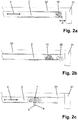
- the carriage 1 is inserted into a C-shaped horizontal running rail 2, which is attached to a furniture ceiling 30 and is open at the bottom, from the open face of the rail. If the horizontal distance A between the running rail 2 and the furniture side wall 31 is too small to thread the assembled carriage 1 into the running rail 2 at the end, the carriage 1 is inserted into the running rail 2 in the disassembled state.
- the operator first introduces the left main body part 10 with the inserted screw nut 7 and then the right main body part 10 into the running rail 2 from the open end of the rail ( Figs. 2a, 2b ) and then over the profile gap of the running rail 2 in the running rail 2 pushed towards one another until the two base body parts 10, 20 are locked together. Finally the screw 8 is screwed into the screw nut 7 from below through the profile gap and secured with the lock nut 9 ( Figure 2c ). The sliding door is attached to the screw 8 protruding downward from the running rail 2.
- the smallest possible distance A is predetermined, at least in the exemplary embodiment shown, by the diameter of the rollers 6.
- the carriage can also be composed of three or more interconnected base body parts which each carry at least one axle of the carriage.
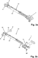
- the two-axis carriage 1 additionally has a self- closing damper 32, known per se, in order to draw the sliding door in a damped manner into its closed or open end position.
- a self- closing damper 32 known per se, in order to draw the sliding door in a damped manner into its closed or open end position.
- One end of the damper housing 33 is articulated to the left main body part 10 via a bearing pin 34 and at its other, free end it carries a parallel axis 5c with two rollers 6. More precisely, there is another on the damper housing 33, here only an example of the left main body part 10 identical base body part 35 connected in an articulated manner via a bearing pin 36.
- the two bearing bolts 34, 36 run parallel to the axes 5a-5c of the rollers 6.
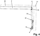
- the self-closing damper 32 is inserted into the open rail face of the running rail 2 ( Fig. 4 ) and the damper housing 33, which is narrower than the profile gap of the running rail 2, swung up in the profile gap into the horizontal position, in which the roller 6 of the left base support part 10 can then be inserted into the open rail face.
- the damper housing 33 which is narrower than the profile gap of the running rail 2, swung up in the profile gap into the horizontal position, in which the roller 6 of the left base support part 10 can then be inserted into the open rail face.
- the articulated connection of the further main body part 35 enables a minimal distance A.
Landscapes
- Engineering & Computer Science (AREA)
- Mechanical Engineering (AREA)
- Support Devices For Sliding Doors (AREA)
Description
- Die Erfindung betrifft einen mehrachsigen Laufwagen für eine hängend geführte Schiebetür mit den Merkmalen des Oberbegriffs von Anspruch 1.
- Ein solcher mehrachsiger Laufwagen für eine hängend geführte Schiebetür ist beispielsweise durch die
DE 198 28 336 A1 bekannt geworden. - Dieser bekannte Laufwagen besteht aus zwei Rollenwagenkörpern, die gelenkig miteinander verbunden sind. Beide Rollenwagenkörper sind von einer senkrecht zur Bewegungsrichtung verlaufenden Querbohrung durchsetzt, die zur Befestigung der Laufrollen dient. Die Verbindung der Rollenwagenkörper erfolgt über angeformte Lageraugen, die sich bei dem einen Rollenwagenkörper in der oberen Hälfte, bei dem anderen Rollenwagenkörper in der unteren Hälfte befinden. Zwischen beiden Lageraugen ist ein Drehlager so angeordnet, daß die Achsen der drei Bauteile fluchten. Das Lager ermöglicht eine Verdrehung der beiden Rollenwagenkörper relativ zueinander. Ein Gegengewindeelement in Form einer Hülse mit einem Innengewinde und einem oberen Bund ist durch das obere Lagerauge des einen Rollenwagenkörpers, die Öffnung im Drehlager und das untere Lagerauge des anderen Rollenwagenkörpers gesteckt und liegt mit ihrem Bund auf der Oberseite des einen Rollenwagenkörpers auf. Ein Gewindeelement in Form eines Gewindestifts ist in die Hülse eingeschraubt und mit einer Mutter gesichert. An dem Gewindestift ist eine Schiebetür hängend befestigt.
- Um einen solchen Laufwagen auch dann, wenn der horizontale Anstand zwischen der Laufschiene und einer Seitenwand (z.B. Möbelseitenwand oder sonstige bauliche Seitenwand) zu gering ist, um den montierten Laufwagen endseitig in eine C-Profil-Laufschiene einzufädeln, dennoch in die Profil-Laufschiene einsetzen zu können, wird erfindungsgemäß ein Laufwagen mit den Merkmalen des Anspruchs 1 vorgeschlagen. Der Grundkörper kann erfindungsgemäß aus zwei, drei oder noch mehr miteinander verbundenen Grundkörperteilen zusammengesetzt sein, die jeweils mindestens eine der Achsen des Laufwagens aufweisen.
- Erfindungsgemäß ist der Laufwagen teilbar ausgebildet, so dass die Grundkörperteile jeweils einzeln, also nacheinander, in die Laufschiene eingeführt und erst nachträglich in der Laufschiene zu dem Grundkörper zusammengesetzt und verbunden werden. Durch das erfindungsgemäße teilbare Laufwagengehäuse kann ein größerer sichtbarer Ausschnitt, um den Laufwagen in die Laufschiene einzubringen, vermieden werden bzw. der hierfür erforderliche Bauraum minimiert werden.
- Vorzugsweise können die Grundkörperteile mindestens einen Vorsprung und mindestens eine Aussparung aufweisen, die bei zusammengestecktem Grundkörper ineinandergreifen, um die Grundkörperteile zueinander auszurichten und insbesondere starr miteinander zu verbinden.
- Bei besonders bevorzugten Ausführungsformen ist an einem der mindestens zwei Grundkörperteile ein Selbsteinzugsdämpfer, insbesondere gelenkig angebunden, um die Schiebetür gedämpft in ihre geschlossene oder geöffnete Endstellung einzuziehen. Vorteilhaft weist der Selbsteinzugsdämpfer an seinem freien Ende eine Achse mit mindestens einer weiteren Laufrolle auf. Dabei kann die Achse mit der mindestens einen weiteren Laufrolle an einem weiteren Grundkörper, der am freien Ende des Selbsteinzugsdämpfers schwenkbar um eine zu den Achsen der Laufrollen parallele Schwenkachse gelagert ist, angeordnet sein, um zusätzlich Bauraum zur Montage zu sparen.
- Die Erfindung betrifft auch ein Verfahren zum Einsetzen des oben beschriebenen mehrachsigen Laufwagens in eine nach unten offene, C-förmige horizontale Laufschiene, gemäß Anspruch 8, wobei erfindungsgemäß die beiden Grundkörperteile jeweils einzeln von der offenen Schienenstirnseite her in die Laufschiene eingeführt und anschließend innerhalb der Laufschiene zu dem Grundkörper zusammengesetzt werden. Dieses Verfahren wird vorteilhaft immer dann angewandt, wenn der horizontale Abstand zwischen der offenen Schienenstirnseite der Laufschiene und einer Seitenwand geringer als der zum Einsetzen des zusammengesetzten Laufwagens erforderliche horizontale Abstand ist.
- Weitere Vorteile der Erfindung ergeben sich aus der Beschreibung, den Ansprüchen und der Zeichnung. Die gezeigten und beschriebenen Ausführungsformen sind nicht als abschließende Aufzählung zu verstehen, sondern haben vielmehr beispielhaften Charakter für die Schilderung der Erfindung.
-
- Fign. 1a, 1b
- einen erfindungsgemäßen Laufwagen am Beispiel einer zweiachsigen Ausführung im zusammengebauten Zustand (
Fig. 1a ) und in einer Explosionsdarstellung (Fig. 1b ); - Fign. 2a-2c
- die einzelnen Montageschritte zum Montieren des in
Fig. 1 gezeigten Laufwagens in einer teilweise aufgeschnitten dargestellten, Cförmigen Laufschiene; - Fign. 3a, 3b
- den in
Fig. 1 gezeigten Laufwagen mit einem zusätzlichen Selbsteinzugsdämpfer im zusammengebauten Zustand (Fig. 3a ) und in einer Explosionsdarstellung (Fig. 3b ); und - Fig. 4
- den ersten Montageschritt zum Montieren des in
Fig. 3 gezeigten Laufwagens mit Selbsteinzugsdämpfer in einer C-förmigen Laufschiene. - Der in
Fign. 1a, 1b gezeigte Laufwagen 1 dient zur Aufhängung einer hängend geführten Schiebetür und ist in einer nach unten offenen C-förmigen, horizontalen Laufschiene 2 (Fig. 2 ) verschiebbar geführt. - Der Laufwagen 1 weist einen Grundkörper 3 und zwei darin drehbar gelagerte, in Laufrichtung 4 des Laufwagens 1 hintereinander angeordnete, parallele Achsen 5a, 5b mit jeweils zwei Laufrollen 6 auf. Der Grundkörper 3 ist aus zwei miteinander verbundenen Grundkörperteilen 10, 20 zusammengesetzt, die jeweils eine der Achsen 5a, 5b aufweisen. Die beiden Grundkörperteile 10, 20 sind einstückige Formteile mit jeweils einer Lagerbohrung 11, 21 für die Achse 5a, 5b und mit jeweils einander zugewandten Kopplungsabschnitten 12, 22.
- Der Kopplungsabschnitt 12 des in
Fig. 1 linken Grundkörperteils 10 umfasst eine nach oben offene Sechskantaufnahme 13, die einen Boden 14 mit einer runden Bodenöffnung 15 aufweist, sowie auf seiner der Achse 5a zugewandten Innenseite eine oberhalb der Sechskantaufnahme 13 parallel zur Achse 5a verlaufende, stirnseitig offene Nut 16 und auf seiner der Achse 5a abgewandten Außenseite zwei Zentriervorsprünge 17. - Der Kopplungsabschnitt 22 des in
Fig. 1 rechten Grundkörperteils 20 umfasst eine stirnseitig offene, U-förmige Steckaufnahme 23, die einen Boden 24 mit einer runden Bodenöffnung 25, eine Decke 26 mit einer runden Deckenöffnung 27 und an der Innenseite des Bodens 24 eine Raste (Rastabsatz) 28 aufweist, sowie zwei Zentrieröffnungen 29 am Grund der Steckaufnahme 23. - Zum Verbinden der beiden Grundkörperteile 10, 20 wird wie folgt vorgegangen: Eine Sechskant-Schraubenmutter 7 wird unverdrehbar in die Sechskantaufnahme 13 des linken Grundkörperteils 10 eingelegt. Anschließend werden - unter elastischer Aufweitung der Steckaufnahme 23 - die Sechskantaufnahme 13 des linken Grundkörperteils 10 und die Steckaufnahme 23 des rechten Grundkörperteils 20 in Laufrichtung 4 ineinandersteckt, bis die Zentriervorsprünge 17 in die Zentrieröffnungen 29 eingreifen, die Decke 26 mit ihrem freien Ende in die Nut 16 eingreift und schließlich die Raste 28 die Schraubenaufnahme 23 verrastend hintergreift. Durch die beim Zusammenfügen ineinander eingreifenden Teile 16, 17, 26, 29 werden die beiden Grundkörperteile 10, 20 zueinander für die Verrastung ausgerichtet. Abschließend wird ein Kopplungselement in Form einer Schraube 8 von unten durch die Bodenlöcher 25, 15 in die Schraubenmutter 7 eingeschraubt, ggf. soweit, bis die Schraube 8 durch die Deckenöffnung 27 nach oben vorsteht. In der gewünschten Endlage kann die Schraube 8 mittels einer Kontermutter 9 gesichert werden.
- Statt wie gezeigt die beiden Grundkörperteile 10, 20 sowohl mittels der Raste 28 als auch mittels der Schraube 8 miteinander zu verbinden, können die beiden Grundkörperteile 10, 20 alternativ nur verrastet oder nur mittels der Schraube 8 miteinander verbunden sein.
- Statt der gezeigten Sechskantaufnahme 13 kann auch jede andere Schraubenmutteraufnahme mit unrundem, z.B. polygonem oder elliptischem Aufnahmequerschnitt und eine Mutter mit entsprechender Außenkontur verwendet werden, solange die Mutter nur unverdrehbar in der Schraubenmutteraufnahme gehalten ist.
- Wie in
Fig. 2 gezeigt, wird der Laufwagen 1 in eine an einer Möbeldecke 30 befestigte, unten offene C-förmige horizontale Laufschiene 2 von der offenen Schienenstirnseite her eingesetzt. Wenn der horizontale Anstand A zwischen Laufschiene 2 und Möbelseitenwand 31 zu gering ist, um den montierten Laufwagen 1 endseitig in die Laufschiene 2 einzufädeln, wird der Laufwagen 1 im zerlegten Zustand in die Laufschiene 2 eingesetzt. Dazu werden vom Bediener zunächst der linke Grundkörperteil 10 mit eingelegter Schraubenmutter 7 und dann der rechte Grundkörperteil 10 jeweils von der offenen Schienenstirnseite her in die Laufschiene 2 eingeführt (Fign. 2a, 2b ) und anschließend über den Profilspalt der Laufschiene 2 in der Laufschiene 2 aufeinander zu geschoben, bis die beiden Grundkörperteile 10, 20 miteinander verrastet sind. Abschließend wird die Schraube 8 von unten durch den Profilspalt in die Schraubenmutter 7 eingeschraubt und mittels der Kontermutter 9 gesichert (Fig. 2c ). An der nach unten aus der Laufschiene 2 vorstehenden Schraube 8 wird die Schiebetür hängend befestigt. - Der kleinstmögliche Abstand A ist, zumindest im gezeigten Ausführungsbeispiel durch den Durchmesser der Laufrollen 6 vorgegeben.
- Statt wie in
Fign. 1 und2 gezeigt aus zwei Grundkörperteilen kann der Laufwagen auch aus drei oder mehr miteinander verbundenen Grundkörperteilen zusammengesetzt sein, die jeweils mindestens eine Achse des Laufwagens tragen. - In
Fign. 3a, 3b weist der zweiachsige Laufwagen 1 zusätzlich einen an sich bekannten Selbsteinzugsdämpfer 32 auf, um die Schiebetür gedämpft in ihre geschlossene oder geöffnete Endstellung einzuziehen. Das Dämpfergehäuse 33 ist an seinem einen Ende über einen Lagerbolzen 34 gelenkig am linken Grundkörperteil 10 angebunden und trägt an seinem anderen, freien Ende eine parallele Achse 5c mit zwei Laufrollen 6. Genauer gesagt ist am Dämpfergehäuse 33 ein weiterer, hier lediglich beispielhaft zum linken Grundkörperteil 10 baugleicher Grundkörperteil 35 über einen Lagerbolzen 36 gelenkig angebunden. Die beiden Lagerbolzen 34, 36 verlaufen parallel zu den Achsen 5a-5c der Laufrollen 6. Mit diesem weiteren Grundkörperteil 35 voran wird der Selbsteinzugsdämpfer 32 in die offene Schienenstirnseite der Laufschiene 2 eingeführt (Fig. 4 ) und dabei das Dämpfergehäuse 33, welches schmaler als der Profilspalt der Laufschiene 2 ist, in dem Profilspalt bis in die horizontale Lage hochgeschwenkt, in der dann auch die Laufrolle 6 des linken Grundträgerteils 10 in die offene Schienenstirnseite eingeführt werden kann. Abschließend werden wie inFig. 2 beschrieben die beiden Grundkörperteile 10, 20 miteinander verbunden. Innerhalb der Laufschiene 2 horizontal belastetem Zustand sperrt sich die Position des inneren Laufwagengehäuseteils an dem Dämpfer selbst in gerader Position. - Im Gegensatz zu einer starren Anbindung ermöglicht die gelenkige Anbindung des weiteren Grundkörperteil 35 einen minimalen Abstand A.
- Durch die nachträgliche Anbindung eines Selbsteinzugsdämpfes 32 können auch Schiebetüren ohne Dämpfungssystem nachträglich mit einem Dämpfungssystem ausgerüstet werden.
Claims (9)
- Mehrachsiger Laufwagen (1) für eine hängend geführte Schiebetür, aufweisend einen Grundkörper (3), der mindestens zwei in Laufrichtung (4) hintereinander angeordnete Achsen (5a, 5b) mit jeweils mindestens einer Laufrolle (6) aufweist, wobei der Grundkörper (3) aus mindestens zwei miteinander verbundenen Grundkörperteilen (10, 20) zusammengesetzt ist, die jeweils mindestens eine der Achsen (5a, 5b) aufweisen und mittels eines Kopplungselements miteinander verbunden sind, das durch Öffnungen (15, 25) der mindestens zwei Grundkörperteile (10, 20) hindurchgreift,
dadurch gekennzeichnet, dass das Kopplungselement durch ein von der Laufwagenunterseite her eingebrachte Schraube (8) gebildet ist, dass der eine Grundkörperteil (10) eine nach oben offene Schraubenmutteraufnahme (13) aufweist, in die eine Schraubenmutter (7) eingelegt ist, in welche die Schraube (8) eingeschraubt ist, und dass der andere Grundkörperteil (20) eine U-förmige Steckaufnahme (23) aufweist, in die bei zusammengestecktem Grundkörper (3) die Schraubenmutteraufnahme (13) eingesteckt ist. - Mehrachsiger Laufwagen nach Anspruch 1, dadurch gekennzeichnet, dass die mindestens zwei Grundkörperteile (10, 20) miteinander in Laufrichtung (4) verrastet sind.
- Mehrachsiger Laufwagen nach einem der vorhergehenden Ansprüche, dadurch gekennzeichnet, dass die mindestens zwei Grundkörperteile (10, 20) mindestens einen Vorsprung (17, 26) und mindestens eine Aussparung (16, 29) aufweisen, die bei zusammengestecktem Grundkörper (3) ineinandergreifen.
- Mehrachsiger Laufwagen nach einem der vorhergehenden Ansprüche, dadurch gekennzeichnet, dass an einem der mindestens zwei Grundkörperteile (10, 20) ein Selbsteinzugsdämpfer (32), insbesondere gelenkig, angebunden ist.
- Mehrachsiger Laufwagen nach Anspruch 4, dadurch gekennzeichnet, dass der Selbsteinzugsdämpfer (32) an seinem freien Ende eine Achse (5c) mit mindestens einer weiteren Laufrolle (6) aufweist.
- Mehrachsiger Laufwagen nach Anspruch 5, dadurch gekennzeichnet, dass die Achse (5c) mit der mindestens einen weiteren Laufrolle (6) an einem weiteren Grundkörper (35) angeordnet ist, der am freien Ende des Selbsteinzugsdämpfers (32) schwenkbar um eine zu den Achsen (5a, 5b) der Laufrollen (6) parallele Schwenkachse gelagert ist.
- Mehrachsiger Laufwagen nach einem der vorhergehenden Ansprüche, dadurch gekennzeichnet, dass der Grundkörper (3) aus drei oder mehr miteinander verbundenen Grundkörperteilen zusammengesetzt ist, die jeweils mindestens eine der Achsen des Laufwagens aufweisen.
- Verfahren zum Einsetzen des mehrachsigen Laufwagens (1) nach einem der vorhergehenden Ansprüche in eine nach unten offene, C-förmige horizontale Laufschiene (2), dadurch gekennzeichnet, dass die mindestens zwei Grundkörperteile (10, 20) jeweils einzeln von der offenen Schienenstirnseite her in die Laufschiene (2) eingeführt und anschließend innerhalb der Laufschiene (2) zu dem Grundkörper (3) zusammengesetzt werden.
- Verfahren nach Anspruch 8, dadurch gekennzeichnet, dass der horizontale Abstand (A) zwischen der offenen Schienenstirnseite der Laufschiene (2) und einer Seitenwand (31) geringer als der zum Einsetzen des zusammengesetzten Laufwagens (5) erforderliche horizontale Abstand ist.
Applications Claiming Priority (2)
| Application Number | Priority Date | Filing Date | Title |
|---|---|---|---|
| DE202016106391.4U DE202016106391U1 (de) | 2016-11-15 | 2016-11-15 | Mehrachsiger Laufwagen für eine hängend geführte Schiebetür |
| PCT/EP2017/078527 WO2018091319A1 (de) | 2016-11-15 | 2017-11-08 | Mehrachsiger laufwagen für eine hängend geführte schiebetür |
Publications (2)
| Publication Number | Publication Date |
|---|---|
| EP3542018A1 EP3542018A1 (de) | 2019-09-25 |
| EP3542018B1 true EP3542018B1 (de) | 2021-02-24 |
Family
ID=57629922
Family Applications (1)
| Application Number | Title | Priority Date | Filing Date |
|---|---|---|---|
| EP17800777.9A Active EP3542018B1 (de) | 2016-11-15 | 2017-11-08 | Mehrachsiger laufwagen für eine hängend geführte schiebetür |
Country Status (4)
| Country | Link |
|---|---|
| EP (1) | EP3542018B1 (de) |
| DE (1) | DE202016106391U1 (de) |
| DK (1) | DK3542018T3 (de) |
| WO (1) | WO2018091319A1 (de) |
Families Citing this family (1)
| Publication number | Priority date | Publication date | Assignee | Title |
|---|---|---|---|---|
| CN110185347B (zh) * | 2019-06-19 | 2024-05-24 | 中山市固美特五金制品有限公司 | 一种便捷装拆式缓冲吊轮 |
Family Cites Families (3)
| Publication number | Priority date | Publication date | Assignee | Title |
|---|---|---|---|---|
| DE19828336B4 (de) * | 1998-06-25 | 2014-02-06 | Geze Gmbh | Laufwerk |
| DE102010036897A1 (de) * | 2010-08-06 | 2012-02-09 | Dorma Gmbh + Co. Kg | Modularer Schiebetürwagen |
| JP5990392B2 (ja) * | 2012-03-30 | 2016-09-14 | 株式会社ニフコ | 可動体のアシスト装置 |
-
2016
- 2016-11-15 DE DE202016106391.4U patent/DE202016106391U1/de not_active Expired - Lifetime
-
2017
- 2017-11-08 EP EP17800777.9A patent/EP3542018B1/de active Active
- 2017-11-08 WO PCT/EP2017/078527 patent/WO2018091319A1/de not_active Ceased
- 2017-11-08 DK DK17800777.9T patent/DK3542018T3/da active
Non-Patent Citations (1)
| Title |
|---|
| None * |
Also Published As
| Publication number | Publication date |
|---|---|
| WO2018091319A1 (de) | 2018-05-24 |
| DK3542018T3 (da) | 2021-04-12 |
| EP3542018A1 (de) | 2019-09-25 |
| DE202016106391U1 (de) | 2016-12-12 |
Similar Documents
| Publication | Publication Date | Title |
|---|---|---|
| DE10119996B4 (de) | Universelle Führungseinrichtung für Schiebetüren eines Möbels | |
| DE3843096C2 (de) | Befestigungseinrichtung für Verkleidungen | |
| DE10008855C2 (de) | Vorrichtung zur Höhenverstellung einer Gleitschiene | |
| AT521133A4 (de) | Führungssystem zur Führung eines bewegbar gelagerten Türflügels | |
| DE602004011617T3 (de) | Einbauscharnier um brillenbügel elastisch zu machen | |
| DE202009018557U1 (de) | Klemmsystem zur Befestigung eines Scharniers und anderen Beschlags an Profilen für Fenster und Türen | |
| EP2503084A1 (de) | Verstellbares Scharnierband | |
| DE202016101091U1 (de) | Türverriegelung | |
| DE102010007128A1 (de) | Dämpfungseinrichtung für schienengeführte Türelemente | |
| WO2018091319A1 (de) | Mehrachsiger laufwagen für eine hängend geführte schiebetür | |
| DE102012011048B4 (de) | Scharniervorrichtung und eine Türanlage mit der Scharniervorrichtung | |
| DE60308578T2 (de) | Stütz-und Führungsanordnung für Schiebetür und entsprechende Tür | |
| DE202008003912U1 (de) | Scharnier für ein Fenster oder eine Tür | |
| EP1963604B1 (de) | Gleitstück für einen beschlag | |
| EP3574813B1 (de) | Scharnier für eine toilettensitzgarnitur | |
| EP3246500B1 (de) | Schiebetürsystem mit dämpferanordnung | |
| DE202015007986U1 (de) | Dreiteiliges höhenverstellbares Türband | |
| EP3146877B1 (de) | Duschkabine | |
| DE102021128938B4 (de) | Höhenverstellbares Band mit Verbindungsmittel | |
| EP3029242B1 (de) | System zur Anordnung eines Türelements an einer Türanlage | |
| AT523523B1 (de) | Schutzvorrichtung | |
| DE102010061411A1 (de) | Verriegelung für einen Türflügel | |
| EP1595048B2 (de) | Fuehrungsrolle fuer laufwagen schiebetueren an kraftdahrzeugen | |
| DE102006051896A1 (de) | Laufwagen für einen Flügel einer Schiebetür oder dergleichen | |
| DE102012216058A1 (de) | Lastabtrageinrichtung für einen gegen einen Rahmen schwenkbaren Flügel |
Legal Events
| Date | Code | Title | Description |
|---|---|---|---|
| STAA | Information on the status of an ep patent application or granted ep patent |
Free format text: STATUS: UNKNOWN |
|
| STAA | Information on the status of an ep patent application or granted ep patent |
Free format text: STATUS: THE INTERNATIONAL PUBLICATION HAS BEEN MADE |
|
| PUAI | Public reference made under article 153(3) epc to a published international application that has entered the european phase |
Free format text: ORIGINAL CODE: 0009012 |
|
| STAA | Information on the status of an ep patent application or granted ep patent |
Free format text: STATUS: REQUEST FOR EXAMINATION WAS MADE |
|
| 17P | Request for examination filed |
Effective date: 20190617 |
|
| AK | Designated contracting states |
Kind code of ref document: A1 Designated state(s): AL AT BE BG CH CY CZ DE DK EE ES FI FR GB GR HR HU IE IS IT LI LT LU LV MC MK MT NL NO PL PT RO RS SE SI SK SM TR |
|
| AX | Request for extension of the european patent |
Extension state: BA ME |
|
| DAV | Request for validation of the european patent (deleted) | ||
| DAX | Request for extension of the european patent (deleted) | ||
| STAA | Information on the status of an ep patent application or granted ep patent |
Free format text: STATUS: EXAMINATION IS IN PROGRESS |
|
| 17Q | First examination report despatched |
Effective date: 20200403 |
|
| GRAP | Despatch of communication of intention to grant a patent |
Free format text: ORIGINAL CODE: EPIDOSNIGR1 |
|
| STAA | Information on the status of an ep patent application or granted ep patent |
Free format text: STATUS: GRANT OF PATENT IS INTENDED |
|
| INTG | Intention to grant announced |
Effective date: 20200923 |
|
| GRAS | Grant fee paid |
Free format text: ORIGINAL CODE: EPIDOSNIGR3 |
|
| GRAA | (expected) grant |
Free format text: ORIGINAL CODE: 0009210 |
|
| STAA | Information on the status of an ep patent application or granted ep patent |
Free format text: STATUS: THE PATENT HAS BEEN GRANTED |
|
| AK | Designated contracting states |
Kind code of ref document: B1 Designated state(s): AL AT BE BG CH CY CZ DE DK EE ES FI FR GB GR HR HU IE IS IT LI LT LU LV MC MK MT NL NO PL PT RO RS SE SI SK SM TR |
|
| REG | Reference to a national code |
Ref country code: CH Ref legal event code: EP |
|
| REG | Reference to a national code |
Ref country code: AT Ref legal event code: REF Ref document number: 1364636 Country of ref document: AT Kind code of ref document: T Effective date: 20210315 |
|
| REG | Reference to a national code |
Ref country code: IE Ref legal event code: FG4D Free format text: LANGUAGE OF EP DOCUMENT: GERMAN |
|
| REG | Reference to a national code |
Ref country code: DE Ref legal event code: R096 Ref document number: 502017009515 Country of ref document: DE |
|
| REG | Reference to a national code |
Ref country code: DK Ref legal event code: T3 Effective date: 20210408 |
|
| REG | Reference to a national code |
Ref country code: SE Ref legal event code: TRGR |
|
| REG | Reference to a national code |
Ref country code: FI Ref legal event code: FGE |
|
| REG | Reference to a national code |
Ref country code: NO Ref legal event code: T2 Effective date: 20210224 |
|
| REG | Reference to a national code |
Ref country code: LT Ref legal event code: MG9D |
|
| REG | Reference to a national code |
Ref country code: NL Ref legal event code: MP Effective date: 20210224 |
|
| PG25 | Lapsed in a contracting state [announced via postgrant information from national office to epo] |
Ref country code: PT Free format text: LAPSE BECAUSE OF FAILURE TO SUBMIT A TRANSLATION OF THE DESCRIPTION OR TO PAY THE FEE WITHIN THE PRESCRIBED TIME-LIMIT Effective date: 20210624 Ref country code: HR Free format text: LAPSE BECAUSE OF FAILURE TO SUBMIT A TRANSLATION OF THE DESCRIPTION OR TO PAY THE FEE WITHIN THE PRESCRIBED TIME-LIMIT Effective date: 20210224 Ref country code: GR Free format text: LAPSE BECAUSE OF FAILURE TO SUBMIT A TRANSLATION OF THE DESCRIPTION OR TO PAY THE FEE WITHIN THE PRESCRIBED TIME-LIMIT Effective date: 20210525 Ref country code: BG Free format text: LAPSE BECAUSE OF FAILURE TO SUBMIT A TRANSLATION OF THE DESCRIPTION OR TO PAY THE FEE WITHIN THE PRESCRIBED TIME-LIMIT Effective date: 20210524 Ref country code: LT Free format text: LAPSE BECAUSE OF FAILURE TO SUBMIT A TRANSLATION OF THE DESCRIPTION OR TO PAY THE FEE WITHIN THE PRESCRIBED TIME-LIMIT Effective date: 20210224 |
|
| PG25 | Lapsed in a contracting state [announced via postgrant information from national office to epo] |
Ref country code: LV Free format text: LAPSE BECAUSE OF FAILURE TO SUBMIT A TRANSLATION OF THE DESCRIPTION OR TO PAY THE FEE WITHIN THE PRESCRIBED TIME-LIMIT Effective date: 20210224 Ref country code: NL Free format text: LAPSE BECAUSE OF FAILURE TO SUBMIT A TRANSLATION OF THE DESCRIPTION OR TO PAY THE FEE WITHIN THE PRESCRIBED TIME-LIMIT Effective date: 20210224 Ref country code: PL Free format text: LAPSE BECAUSE OF FAILURE TO SUBMIT A TRANSLATION OF THE DESCRIPTION OR TO PAY THE FEE WITHIN THE PRESCRIBED TIME-LIMIT Effective date: 20210224 Ref country code: RS Free format text: LAPSE BECAUSE OF FAILURE TO SUBMIT A TRANSLATION OF THE DESCRIPTION OR TO PAY THE FEE WITHIN THE PRESCRIBED TIME-LIMIT Effective date: 20210224 |
|
| PG25 | Lapsed in a contracting state [announced via postgrant information from national office to epo] |
Ref country code: IS Free format text: LAPSE BECAUSE OF FAILURE TO SUBMIT A TRANSLATION OF THE DESCRIPTION OR TO PAY THE FEE WITHIN THE PRESCRIBED TIME-LIMIT Effective date: 20210624 |
|
| PG25 | Lapsed in a contracting state [announced via postgrant information from national office to epo] |
Ref country code: EE Free format text: LAPSE BECAUSE OF FAILURE TO SUBMIT A TRANSLATION OF THE DESCRIPTION OR TO PAY THE FEE WITHIN THE PRESCRIBED TIME-LIMIT Effective date: 20210224 Ref country code: CZ Free format text: LAPSE BECAUSE OF FAILURE TO SUBMIT A TRANSLATION OF THE DESCRIPTION OR TO PAY THE FEE WITHIN THE PRESCRIBED TIME-LIMIT Effective date: 20210224 Ref country code: SM Free format text: LAPSE BECAUSE OF FAILURE TO SUBMIT A TRANSLATION OF THE DESCRIPTION OR TO PAY THE FEE WITHIN THE PRESCRIBED TIME-LIMIT Effective date: 20210224 |
|
| REG | Reference to a national code |
Ref country code: DE Ref legal event code: R097 Ref document number: 502017009515 Country of ref document: DE |
|
| PG25 | Lapsed in a contracting state [announced via postgrant information from national office to epo] |
Ref country code: RO Free format text: LAPSE BECAUSE OF FAILURE TO SUBMIT A TRANSLATION OF THE DESCRIPTION OR TO PAY THE FEE WITHIN THE PRESCRIBED TIME-LIMIT Effective date: 20210224 Ref country code: SK Free format text: LAPSE BECAUSE OF FAILURE TO SUBMIT A TRANSLATION OF THE DESCRIPTION OR TO PAY THE FEE WITHIN THE PRESCRIBED TIME-LIMIT Effective date: 20210224 |
|
| PLBE | No opposition filed within time limit |
Free format text: ORIGINAL CODE: 0009261 |
|
| STAA | Information on the status of an ep patent application or granted ep patent |
Free format text: STATUS: NO OPPOSITION FILED WITHIN TIME LIMIT |
|
| PG25 | Lapsed in a contracting state [announced via postgrant information from national office to epo] |
Ref country code: AL Free format text: LAPSE BECAUSE OF FAILURE TO SUBMIT A TRANSLATION OF THE DESCRIPTION OR TO PAY THE FEE WITHIN THE PRESCRIBED TIME-LIMIT Effective date: 20210224 Ref country code: ES Free format text: LAPSE BECAUSE OF FAILURE TO SUBMIT A TRANSLATION OF THE DESCRIPTION OR TO PAY THE FEE WITHIN THE PRESCRIBED TIME-LIMIT Effective date: 20210224 |
|
| 26N | No opposition filed |
Effective date: 20211125 |
|
| PG25 | Lapsed in a contracting state [announced via postgrant information from national office to epo] |
Ref country code: SI Free format text: LAPSE BECAUSE OF FAILURE TO SUBMIT A TRANSLATION OF THE DESCRIPTION OR TO PAY THE FEE WITHIN THE PRESCRIBED TIME-LIMIT Effective date: 20210224 |
|
| PG25 | Lapsed in a contracting state [announced via postgrant information from national office to epo] |
Ref country code: IT Free format text: LAPSE BECAUSE OF FAILURE TO SUBMIT A TRANSLATION OF THE DESCRIPTION OR TO PAY THE FEE WITHIN THE PRESCRIBED TIME-LIMIT Effective date: 20210224 |
|
| PG25 | Lapsed in a contracting state [announced via postgrant information from national office to epo] |
Ref country code: IS Free format text: LAPSE BECAUSE OF FAILURE TO SUBMIT A TRANSLATION OF THE DESCRIPTION OR TO PAY THE FEE WITHIN THE PRESCRIBED TIME-LIMIT Effective date: 20210624 |
|
| PG25 | Lapsed in a contracting state [announced via postgrant information from national office to epo] |
Ref country code: MC Free format text: LAPSE BECAUSE OF FAILURE TO SUBMIT A TRANSLATION OF THE DESCRIPTION OR TO PAY THE FEE WITHIN THE PRESCRIBED TIME-LIMIT Effective date: 20210224 |
|
| REG | Reference to a national code |
Ref country code: CH Ref legal event code: PL |
|
| PG25 | Lapsed in a contracting state [announced via postgrant information from national office to epo] |
Ref country code: LU Free format text: LAPSE BECAUSE OF NON-PAYMENT OF DUE FEES Effective date: 20211108 Ref country code: BE Free format text: LAPSE BECAUSE OF NON-PAYMENT OF DUE FEES Effective date: 20211130 |
|
| REG | Reference to a national code |
Ref country code: BE Ref legal event code: MM Effective date: 20211130 |
|
| PG25 | Lapsed in a contracting state [announced via postgrant information from national office to epo] |
Ref country code: IE Free format text: LAPSE BECAUSE OF NON-PAYMENT OF DUE FEES Effective date: 20211108 |
|
| PG25 | Lapsed in a contracting state [announced via postgrant information from national office to epo] |
Ref country code: FR Free format text: LAPSE BECAUSE OF NON-PAYMENT OF DUE FEES Effective date: 20211130 |
|
| PG25 | Lapsed in a contracting state [announced via postgrant information from national office to epo] |
Ref country code: CY Free format text: LAPSE BECAUSE OF FAILURE TO SUBMIT A TRANSLATION OF THE DESCRIPTION OR TO PAY THE FEE WITHIN THE PRESCRIBED TIME-LIMIT Effective date: 20210224 |
|
| PG25 | Lapsed in a contracting state [announced via postgrant information from national office to epo] |
Ref country code: LI Free format text: LAPSE BECAUSE OF NON-PAYMENT OF DUE FEES Effective date: 20220630 Ref country code: HU Free format text: LAPSE BECAUSE OF FAILURE TO SUBMIT A TRANSLATION OF THE DESCRIPTION OR TO PAY THE FEE WITHIN THE PRESCRIBED TIME-LIMIT; INVALID AB INITIO Effective date: 20171108 Ref country code: CH Free format text: LAPSE BECAUSE OF NON-PAYMENT OF DUE FEES Effective date: 20220630 |
|
| P01 | Opt-out of the competence of the unified patent court (upc) registered |
Effective date: 20230630 |
|
| REG | Reference to a national code |
Ref country code: AT Ref legal event code: MM01 Ref document number: 1364636 Country of ref document: AT Kind code of ref document: T Effective date: 20221108 |
|
| PG25 | Lapsed in a contracting state [announced via postgrant information from national office to epo] |
Ref country code: AT Free format text: LAPSE BECAUSE OF NON-PAYMENT OF DUE FEES Effective date: 20221108 |
|
| PG25 | Lapsed in a contracting state [announced via postgrant information from national office to epo] |
Ref country code: MK Free format text: LAPSE BECAUSE OF FAILURE TO SUBMIT A TRANSLATION OF THE DESCRIPTION OR TO PAY THE FEE WITHIN THE PRESCRIBED TIME-LIMIT Effective date: 20210224 |
|
| PG25 | Lapsed in a contracting state [announced via postgrant information from national office to epo] |
Ref country code: MT Free format text: LAPSE BECAUSE OF FAILURE TO SUBMIT A TRANSLATION OF THE DESCRIPTION OR TO PAY THE FEE WITHIN THE PRESCRIBED TIME-LIMIT Effective date: 20210224 |
|
| PGFP | Annual fee paid to national office [announced via postgrant information from national office to epo] |
Ref country code: NO Payment date: 20241119 Year of fee payment: 8 |
|
| PGFP | Annual fee paid to national office [announced via postgrant information from national office to epo] |
Ref country code: DK Payment date: 20241120 Year of fee payment: 8 |
|
| PGFP | Annual fee paid to national office [announced via postgrant information from national office to epo] |
Ref country code: FI Payment date: 20241119 Year of fee payment: 8 |
|
| PGFP | Annual fee paid to national office [announced via postgrant information from national office to epo] |
Ref country code: GB Payment date: 20241121 Year of fee payment: 8 |
|
| PGFP | Annual fee paid to national office [announced via postgrant information from national office to epo] |
Ref country code: SE Payment date: 20241120 Year of fee payment: 8 |
|
| PG25 | Lapsed in a contracting state [announced via postgrant information from national office to epo] |
Ref country code: TR Free format text: LAPSE BECAUSE OF FAILURE TO SUBMIT A TRANSLATION OF THE DESCRIPTION OR TO PAY THE FEE WITHIN THE PRESCRIBED TIME-LIMIT Effective date: 20210224 |
|
| PGFP | Annual fee paid to national office [announced via postgrant information from national office to epo] |
Ref country code: DE Payment date: 20251126 Year of fee payment: 9 |