EP3541982B1 - Heizsystem für eine vorrichtung zur beatmung von textilien - Google Patents
Heizsystem für eine vorrichtung zur beatmung von textilien Download PDFInfo
- Publication number
- EP3541982B1 EP3541982B1 EP17807791.3A EP17807791A EP3541982B1 EP 3541982 B1 EP3541982 B1 EP 3541982B1 EP 17807791 A EP17807791 A EP 17807791A EP 3541982 B1 EP3541982 B1 EP 3541982B1
- Authority
- EP
- European Patent Office
- Prior art keywords
- drum
- treating apparatus
- laundry treating
- unit
- power
- Prior art date
- Legal status (The legal status is an assumption and is not a legal conclusion. Google has not performed a legal analysis and makes no representation as to the accuracy of the status listed.)
- Active
Links
Images



Classifications
-
- D—TEXTILES; PAPER
- D06—TREATMENT OF TEXTILES OR THE LIKE; LAUNDERING; FLEXIBLE MATERIALS NOT OTHERWISE PROVIDED FOR
- D06F—LAUNDERING, DRYING, IRONING, PRESSING OR FOLDING TEXTILE ARTICLES
- D06F34/00—Details of control systems for washing machines, washer-dryers or laundry dryers
- D06F34/14—Arrangements for detecting or measuring specific parameters
- D06F34/22—Condition of the washing liquid, e.g. turbidity
- D06F34/24—Liquid temperature
-
- D—TEXTILES; PAPER
- D06—TREATMENT OF TEXTILES OR THE LIKE; LAUNDERING; FLEXIBLE MATERIALS NOT OTHERWISE PROVIDED FOR
- D06F—LAUNDERING, DRYING, IRONING, PRESSING OR FOLDING TEXTILE ARTICLES
- D06F39/00—Details of washing machines not specific to a single type of machines covered by groups D06F9/00 - D06F27/00
- D06F39/04—Heating arrangements
-
- D—TEXTILES; PAPER
- D06—TREATMENT OF TEXTILES OR THE LIKE; LAUNDERING; FLEXIBLE MATERIALS NOT OTHERWISE PROVIDED FOR
- D06F—LAUNDERING, DRYING, IRONING, PRESSING OR FOLDING TEXTILE ARTICLES
- D06F34/00—Details of control systems for washing machines, washer-dryers or laundry dryers
- D06F34/10—Power supply arrangements, e.g. stand-by circuits
-
- D—TEXTILES; PAPER
- D06—TREATMENT OF TEXTILES OR THE LIKE; LAUNDERING; FLEXIBLE MATERIALS NOT OTHERWISE PROVIDED FOR
- D06F—LAUNDERING, DRYING, IRONING, PRESSING OR FOLDING TEXTILE ARTICLES
- D06F58/00—Domestic laundry dryers
- D06F58/20—General details of domestic laundry dryers
- D06F58/26—Heating arrangements, e.g. gas heating equipment
-
- H—ELECTRICITY
- H01—ELECTRIC ELEMENTS
- H01F—MAGNETS; INDUCTANCES; TRANSFORMERS; SELECTION OF MATERIALS FOR THEIR MAGNETIC PROPERTIES
- H01F27/00—Details of transformers or inductances, in general
- H01F27/28—Coils; Windings; Conductive connections
- H01F27/288—Shielding
-
- H—ELECTRICITY
- H02—GENERATION; CONVERSION OR DISTRIBUTION OF ELECTRIC POWER
- H02J—ELECTRIC POWER NETWORKS; CIRCUIT ARRANGEMENTS OR SYSTEMS FOR SUPPLYING OR DISTRIBUTING ELECTRIC POWER; SYSTEMS FOR STORING ELECTRIC ENERGY
- H02J50/00—Circuit arrangements or systems for wireless supply or distribution of electric power
- H02J50/10—Circuit arrangements or systems for wireless supply or distribution of electric power using inductive coupling
-
- D—TEXTILES; PAPER
- D06—TREATMENT OF TEXTILES OR THE LIKE; LAUNDERING; FLEXIBLE MATERIALS NOT OTHERWISE PROVIDED FOR
- D06F—LAUNDERING, DRYING, IRONING, PRESSING OR FOLDING TEXTILE ARTICLES
- D06F2103/00—Parameters monitored or detected for the control of domestic laundry washing machines, washer-dryers or laundry dryers
- D06F2103/16—Washing liquid temperature
-
- D—TEXTILES; PAPER
- D06—TREATMENT OF TEXTILES OR THE LIKE; LAUNDERING; FLEXIBLE MATERIALS NOT OTHERWISE PROVIDED FOR
- D06F—LAUNDERING, DRYING, IRONING, PRESSING OR FOLDING TEXTILE ARTICLES
- D06F2105/00—Systems or parameters controlled or affected by the control systems of washing machines, washer-dryers or laundry dryers
- D06F2105/10—Temperature of washing liquids; Heating means therefor
-
- D—TEXTILES; PAPER
- D06—TREATMENT OF TEXTILES OR THE LIKE; LAUNDERING; FLEXIBLE MATERIALS NOT OTHERWISE PROVIDED FOR
- D06F—LAUNDERING, DRYING, IRONING, PRESSING OR FOLDING TEXTILE ARTICLES
- D06F25/00—Washing machines with receptacles, e.g. perforated, having a rotary movement, e.g. oscillatory movement, the receptacle serving both for washing and for centrifugally separating water from the laundry and having further drying means, e.g. using hot air
-
- D—TEXTILES; PAPER
- D06—TREATMENT OF TEXTILES OR THE LIKE; LAUNDERING; FLEXIBLE MATERIALS NOT OTHERWISE PROVIDED FOR
- D06F—LAUNDERING, DRYING, IRONING, PRESSING OR FOLDING TEXTILE ARTICLES
- D06F34/00—Details of control systems for washing machines, washer-dryers or laundry dryers
- D06F34/04—Signal transfer or data transmission arrangements
- D06F34/05—Signal transfer or data transmission arrangements for wireless communication between components, e.g. for remote monitoring or control
-
- D—TEXTILES; PAPER
- D06—TREATMENT OF TEXTILES OR THE LIKE; LAUNDERING; FLEXIBLE MATERIALS NOT OTHERWISE PROVIDED FOR
- D06F—LAUNDERING, DRYING, IRONING, PRESSING OR FOLDING TEXTILE ARTICLES
- D06F37/00—Details specific to washing machines covered by groups D06F21/00 - D06F25/00
- D06F37/02—Rotary receptacles, e.g. drums
- D06F37/04—Rotary receptacles, e.g. drums adapted for rotation or oscillation about a horizontal or inclined axis
- D06F37/06—Ribs, lifters, or rubbing means forming part of the receptacle
- D06F37/065—Ribs, lifters, or rubbing means forming part of the receptacle ribs or lifters having means for circulating the washing liquid
-
- Y—GENERAL TAGGING OF NEW TECHNOLOGICAL DEVELOPMENTS; GENERAL TAGGING OF CROSS-SECTIONAL TECHNOLOGIES SPANNING OVER SEVERAL SECTIONS OF THE IPC; TECHNICAL SUBJECTS COVERED BY FORMER USPC CROSS-REFERENCE ART COLLECTIONS [XRACs] AND DIGESTS
- Y02—TECHNOLOGIES OR APPLICATIONS FOR MITIGATION OR ADAPTATION AGAINST CLIMATE CHANGE
- Y02B—CLIMATE CHANGE MITIGATION TECHNOLOGIES RELATED TO BUILDINGS, e.g. HOUSING, HOUSE APPLIANCES OR RELATED END-USER APPLICATIONS
- Y02B40/00—Technologies aiming at improving the efficiency of home appliances, e.g. induction cooking or efficient technologies for refrigerators, freezers or dish washers
Definitions
- the invention relates to a heating and control system for a washer or dryer appliance for heating water to be used in the washing cycle or clothes in the drying cycle.
- JP 2005 177331 discloses a washing machine which includes induction heating means for electromagnetic induction heating of the tub wall of the washing machine.
- US 2016/330572 A1 discloses a wireless communication assembly that includes a driver module connected to a first portion of a machine, such as a laundry machine, and a receiver module connected to a second portion of the machine, such as a rotatable drum.
- the first module includes a primary coil configured to generate an electromagnetic field and a first wireless transceiver.
- the second module includes a secondary coil configured to convert energy within the electromagnetic field into electric power, and a second wireless transceiver powered by the secondary coil and configured to communicate with the first wireless transceiver.
- One or more sensors may be positioned within the drum to measure various conditions.
- the receiver module may be powered by the secondary coil and when powered on, may communicate data from the one or more sensors to the first module.
- EP 2302125 A1 discloses a washing machine including a washing tub, a washing drum rotatably arranged within the washing tub, and at least one electric heating element associated to the washing drum.
- the at least one heating element is arranged at the outer surface of a peripheral wall of the washing drum.
- the washing machine comprises a suitable rotatable transformer, adapted to deliver electric energy to the electric power supply lines connected to the heating elements, comprising a first rotating wire coil, electrically connected to the power supply lines and associated to a shaft connecting the washing drum to the motor (and therefore rotatable with respect to the washing tub), and a second stationary wire coil (inductively coupled with the first wire coil), electrically connectable to the supply mains and stationary with respect to the washing tub; electric power may be delivered to the power supply lines by electromagnetic induction, and therefore without using a slip-ring device.
- a suitable rotatable transformer adapted to deliver electric energy to the electric power supply lines connected to the heating elements, comprising a first rotating wire coil, electrically connected to the power supply lines and associated to a shaft connecting the washing drum to the motor (and therefore rotatable with respect to the washing tub), and a second stationary wire coil (inductively coupled with the first wire coil), electrically connectable to the supply mains and stationary with respect to the washing tub; electric power may be delivered to the power supply
- a heating element in the washer or washer dryer drum supplied by an electromagnetic coupling between a power transmitter unit positioned on the tub side and a power receiver unit fixed on the drum side opposite to the power transmitter unit.
- a first embodiment foresees three heating elements integrated in the lifters in the drum.
- a power transmitter unit fixed to the tub transfers the electric power through magnetic coupling to a power receiver unit fixed to the drum.
- Electric wires in the drum connect the power receiver unit to the heating elements.
- the appliance power control unit controls directly the power generated by the heating elements through the power supplied to the power transmit unit.
- an interface unit in the drum that provides wireless to the appliance control unit temperature measurement data.
- the interface unit supplies wireless, temperatures and other measured parameters to the appliance control unit.
- the present invention thus relates to a laundry treating apparatus comprising a tub, a drum rotatably mounted inside the tub, at least one electric element mounted in the drum, a wireless power transmitter unit and a wireless power receiver unit, characterized in that the wireless power receiver unit supplies power to the at least one electric element.
- the at least one electric element preferably comprises at least one heating element.
- the at least one electric element may comprise at least one interface unit designed to wirelessly transmit data. More in general, the at least one electric element may comprise a wireless transmission device.
- the electric element may comprise at least one sensor element.
- the apparatus which advantageously comprises an appliance control unit, may have at least one sensor element fixed to the drum and designed to generated measurement data; in such case, the at least one interface unit is designed to wirelessly transmit said measurement data to the control unit.
- the power transmitter unit and the power receiver unit are positioned, one opposite to the other, fixed respectively to the tub and to the drum, parallel in radial direction.
- the power transmitter unit comprises a transmission coil generating a magnetic field and the power receiver unit comprises a reception coil generating power from the magnetic field generated by the transmission coil and supplying the generated power to the at least one electric element.
- the transmission coil and the reception coil are preferably aligned, centered and parallel in radial direction.
- the transmission coil and the reception coil preferably have a common radius dimension approximately equal to the drum external radius and are distanced in axial direction by a distance lower (typically much lower) than their radius.
- Such distance is preferably lower than 10 cm, more preferably lower than 5 cm.
- the power receiver unit comprises a reception coil and a receiver shielding member
- the transmitter unit comprises a transmission coil and a transmission shielding member
- the receiver shielding member is positioned between the reception coil and the drum side, and the transmission shielding member is positioned between the transmission coil and the tub side.
- the receiver magnetic shielding member is preferably positioned on the opposite side of the reception coil with respect to the power transmitter unit.
- the transmission magnetic shielding member is preferably positioned on the opposite side of the transmission coil with respect to the power receiver unit.
- the power receiver unit comprises at least two reception coils and the at least one electric element comprises at least two electric elements, the at least two reception coils supplying the at least two electric elements.
- the drum comprises at least one drum lifter and in the at least one electric element is integrated in the at least one drum lifter.
- the drum comprises at least one drum lifter and in the at least one sensor element comprises at least one temperature sensing element positioned in the at least one drum lifter and designed to generate temperature measurement data.
- the apparatus advantageously comprises an appliance control unit and the at least one electric element preferably comprises at least one interface unit designed to wirelessly transmit said temperature measurement data to the control unit.
- the at least one interface unit is preferably fixed to the drum and the power receiver unit preferably comprises a reception coil supplying the at least one interface unit.
- the at least one interface unit may be fixed to a central radial portion of the drum.
- the interface unit is preferably configured to wirelessly transmit to the control unit also further measurement data received from at least another sensor element.
- the drum advantageously comprises at least one drum lifter and the at least one sensor element preferably comprises at least one temperature sensing element positioned in the at least one drum lifter and designed to generate temperature measurement data.
- the apparatus advantageously comprises an appliance control unit and the at least one electric element preferably comprises at least one interface unit designed to wirelessly transmit said temperature measurement data to the control unit.
- Fig. 1 it is shown a sectional view of the key structural parts of a horizontal axis washer 10.
- the wash unit consisting of the tub 30 on which is rotatably mounted a drum 50.
- the wash unit is suspended to the cabinet 20 through springs 40 and dumpers 80.
- a power supply receiver unit 63 At the external front side, corresponding to the drum 50 opening side, of the drum 50 is fixed a power supply receiver unit 63.
- the receiver power unit 63 is electromagnetically coupled to a power supply transmitter unit 62 fixed to the Tub 50.
- the drum 50 has three drum lifters 500, disposed 120 degrees spaced, to lift the clothes in the washing cycle.
- a heating element 200 As shown in Fig. 2 a sectional view of the drum 50 taken in radial direction.
- the power receiver unit 63 through electric wires supplies the heating elements 200.
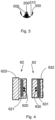
- Fig. 3 is shown in detail the sectional view of a lifter 500.
- the heating element 200 is integrated in the lifter 500, it could be cylindrical shaped having the same length as the lifter 500 in axial direction.
- the opening 510 in the lifter 500 can allow the water to get inside the lifter 500 facilitating the heat exchange between the heating element 200 and the water in the drum 50.
- the heat exchange surface between the heating elements and the mix of the water and clothes in the drum 50 is very high. It avoids high heat transfer concentration on a small surface and allows a faster efficient and safe heating process.
- the power receiver unit 63 is fixed parallel in radial direction opposite the power transmitter unit 62.
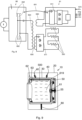
- Fig. 4 is shown a sectional view of the power transmitter unit 62 and receiver unit 63.
- the power transmitter unit 62 has a transmission coil 620 which is electromagnetically coupled to the reception coil 630 of the power receiver unit 63. They are integrated into the enclosing material 622, 632 and have respectively the magnetic sheets 621 and 631 that provide the side magnetic shield to the sides external to the coupling area and improve the magnetic coupling between the two coils 622 and 632.
- the power receiver unit 63 could be fixed in a U shaped opening formed in the drum 50 external periphery, while the power transmitter unit could have its side 622 fixed with screw or glued to the tub 30 wall.
- the appliance control unit 60 it is generated the oscillating voltage by switching elements 602 that supply the transmission coil 620 of the power transmitter unit 62 coupled to the reception coil 630 of the power receiver unit 63.
- the voltage induced in the coil 630 is rectified and conditioned in the coil interface block 611 and brought with wires to the three heating elements 200 connected in series.
- the few components of the interface block 611 could be integrated in the power receiver unit 63.
- the appliance control unit 60 manages the complete washer (10) operation, controlling the drum motor rotation speed as well as the other appliance 10 actuators e.g. the drain pump (not shown in Fig. 8 ).
- the appliance control units 60 can measure the water temperature in the Tub 30 and generate the proper voltage supplying the heating elements through its switching element 602.
- FIG. 7 Another embodiment is shown in Fig. 7 where the power receiver unit 63 has multiple coils 630, each coil 630 supplying through its own interface block 611 a heating element 200.
- FIG. 8 One further advantageous embodiment is shown in Fig. 8 .
- the interface unit 61 can be supplied by a dedicated reception coil 640 of the receiver unit 63, as shown in Fig. 8 , or it could be connected in parallel to the reception coil 630 supplying the heating elements 200.
- the interface unit 61 has a wireless connection 601 to transfer measurement data to the appliance control unit 60.
- the interface unit 61 could transfer to the appliance control unit 60 measured temperatures 615 from temperature measurement elements positioned in the lifters 500.
- the interface unit 61 could be positioned integrated in the isolating support material 632 of the power receiver unit 63. Or it could be positioned on the drum 50 external side at the centre, between the drum and the cross-piece.
- FIG. 9 shows the interface unit 61 positioned on the drum 50 external side in the central area (55).
- the biggest advantage of this position 55 is that the interface unit 61 components are not subject to the high centrifugal forces.
- the interface unit 61 could sense and send additional measurement parameters, not only temperatures 615, but also e.g. water level, unbalance, providing all needed sensing information 616 to the appliance control unit 60.
- the appliance control unit 60 could be designed only to drive actuators like drain pump, inlet valve, drum motor and the power transmitter unit 62.
- the wireless power receiver unit can supply power to any type of electric element mounted on the drum or fixed to the drum, including heating elements, signal transmission and/or reception elements (like wireless data transmission and/or reception devices) and sensor elements (like temperature sensors, water level sensors, humidity sensors, movement sensors such as speed or acceleration sensors).
- heating elements like wireless data transmission and/or reception devices
- sensor elements like temperature sensors, water level sensors, humidity sensors, movement sensors such as speed or acceleration sensors.
Landscapes
- Engineering & Computer Science (AREA)
- Textile Engineering (AREA)
- Power Engineering (AREA)
- Computer Networks & Wireless Communication (AREA)
- Control Of Washing Machine And Dryer (AREA)
- Drying Of Solid Materials (AREA)
Claims (18)
- Wäschebehandlungsvorrichtung (10), umfassend einen Laugenbehälter (30), eine Trommel (50), die drehbar innerhalb des Laugenbehälters (30) angebracht ist, mindestens ein elektrisches Element (200, 61), das in der Trommel (50) angebracht ist, eine drahtlose Leistungsübertragungseinheit (62) und eine drahtlose Leistungsempfängereinheit (63), wobei die drahtlose Leistungsempfängereinheit (63) das mindestens eine elektrische Element (200, 61) mit Leistung versorgt, wobei
die Leistungsübertragungseinheit (62) und die Leistungsempfängereinheit (63) einander gegenüberliegend positioniert sind, an dem Laugenbehälter (30) bzw. an der Trommel (50) befestigt sind, in radialer Richtung parallel an dem Laugenbehälter (30) bzw. an der Trommel (50) angebracht sind und mit der Trommelmitte zentriert sind, dadurch gekennzeichnet, dass die Leistungsübertragungseinheit (62) und die Leistungsempfängereinheit (63) ringförmig sind. - Wäschebehandlungsvorrichtung (10) nach Anspruch 1, dadurch gekennzeichnet, dass das mindestens eine elektrische Element (200, 61) mindestens ein Heizelement (200) umfasst.
- Wäschebehandlungsvorrichtung (10) nach Anspruch 1 oder 2, dadurch gekennzeichnet, dass das mindestens eine elektrische Element (200, 61) mindestens eine Schnittstelleneinheit (61) umfasst, die für drahtlose Datenübertragung ausgelegt ist.
- Wäschebehandlungsvorrichtung (10) nach einem der vorhergehenden Ansprüche, dadurch gekennzeichnet, dass das elektrische Element (200, 61) mindestens ein Sensorelement umfasst.
- Wäschebehandlungsvorrichtung (10) nach Anspruch 3, dadurch gekennzeichnet, dass die Vorrichtung eine Gerätesteuereinheit (60) und mindestens ein Sensorelement umfasst, das an der Trommel (50) befestigt und zur Erzeugung von Messdaten ausgelegt ist, wobei die mindestens eine Schnittstelleneinheit (61) für drahtlose Übertragung der Messdaten an die Steuereinheit (60) ausgelegt ist.
- Wäschebehandlungsvorrichtung (10) nach einem der vorhergehenden Ansprüche, dadurch gekennzeichnet, dass die Leistungsübertragungseinheit (62) eine Übertragungsspule (620) umfasst, die ein Magnetfeld erzeugt, und die Leistungsempfängereinheit (63) eine Empfangsspule (630) umfasst, die aus dem von der Übertragungsspule (620) erzeugten Magnetfeld Leistung erzeugt und die erzeugte Leistung an das mindestens eine elektrische Element (200, 61) liefert.
- Wäschebehandlungsvorrichtung (10) nach Anspruch 6, dadurch gekennzeichnet, dass die Übertragungsspule (620) und die Empfangsspule (630) in radialer Richtung ausgerichtet, zentriert und parallel sind.
- Wäschebehandlungsvorrichtung (10) nach Anspruch 7, dadurch gekennzeichnet, dass die Übertragungsspule (620) und die Empfangsspule (630) eine gemeinsame Radiusabmessung aufweisen, die ungefähr gleich dem Außenradius der Trommel (50) ist, und in axialer Richtung um einen Abstand beabstandet sind, der kleiner als ihr Radius ist.
- Wäschebehandlungsvorrichtung (10) nach Anspruch 8, dadurch gekennzeichnet, dass die Übertragungsspule (620) und die Empfangsspule (630) in axialer Richtung um einen Abstand von weniger als 10 cm oder weniger als 5 cm beabstandet sind.
- Wäschebehandlungsvorrichtung (10) nach einem der vorhergehenden Ansprüche, dadurch gekennzeichnet, dass die Leistungsempfängereinheit (63) eine Empfangsspule (630) und ein magnetisches Empfängerabschirmelement (631) umfasst, und die Übertragungseinheit (62) eine Übertragungsspule (620) und ein magnetisches Übertragungsabschirmelement (621) umfasst, wobei das magnetische Empfängerabschirmelement (631) zwischen der Empfangsspule (630) und der Seite der Trommel (50) positioniert ist, und das magnetische Übertragungsabschirmelement (621) zwischen der Übertragungsspule (620) und der Seite des Laugenbehälters (30) positioniert ist.
- Wäschebehandlungsvorrichtung (10) nach einem der vorhergehenden Ansprüche, dadurch gekennzeichnet, dass die Leistungsempfängereinheit (63) mindestens zwei Empfangsspulen (630) umfasst und das mindestens eine elektrische Element (200, 61) mindestens zwei elektrische Elemente (200, 61) umfasst, wobei die mindestens zwei Empfangsspulen (630) die mindestens zwei elektrischen Elemente (200, 61) versorgen.
- Wäschebehandlungsvorrichtung (10) nach einem der vorhergehenden Ansprüche, dadurch gekennzeichnet, dass die Trommel (50) mindestens einen Trommelheber (500) umfasst und dass das mindestens eine elektrische Element (200) in den mindestens einen Trommelheber (500) integriert ist.
- Wäschebehandlungsvorrichtung (10) nach Anspruch 4, dadurch gekennzeichnet, dass die Trommel (50) mindestens einen Trommelheber (500) umfasst und dass das mindestens eine Sensorelement mindestens ein Temperaturerfassungselement umfasst, das in dem mindestens einen Trommelheber (500) positioniert und zur Erzeugung von Temperaturmessdaten ausgelegt ist.
- Wäschebehandlungsvorrichtung (10) nach Anspruch 13, dadurch gekennzeichnet, dass die Vorrichtung eine Gerätesteuereinheit (60) umfasst und das mindestens eine elektrische Element (200, 61) mindestens eine Schnittstelleneinheit (61) umfasst, die so ausgelegt ist, dass sie die Temperaturmessdaten drahtlos an die Steuereinheit (60) überträgt.
- Wäschebehandlungsvorrichtung (10) nach Anspruch 14, dadurch gekennzeichnet, dass die Leistungsempfängereinheit (63) eine Empfangsspule (630) umfasst, die die mindestens eine Schnittstelleneinheit (61) versorgt, und dass die mindestens eine Schnittstelleneinheit (61) an der Trommel (50), insbesondere an einem zentralen radialen Abschnitt der Trommel (50), befestigt ist.
- Wäschebehandlungsvorrichtung (10) nach Anspruch 14, dadurch gekennzeichnet, dass die Schnittstelleneinheit (61) so konfiguriert ist, dass sie ferner weitere von mindestens einem anderen Sensorelement empfangene Messdaten drahtlos an die Steuereinheit (60) überträgt.
- Wäschebehandlungsvorrichtung (10) nach Anspruch 3, dadurch gekennzeichnet, dass die Trommel (50) mindestens einen Trommelheber (500) umfasst und dass das mindestens eine Sensorelement mindestens ein Temperaturerfassungselement umfasst, das in dem mindestens einen Trommelheber (500) positioniert und zur Erzeugung von Temperaturmessdaten ausgelegt ist.
- Wäschebehandlungsvorrichtung (10) nach Anspruch 17, dadurch gekennzeichnet, dass die Vorrichtung eine Gerätesteuereinheit (60) umfasst und das mindestens eine elektrische Element (200, 61) mindestens eine Schnittstelleneinheit (61) umfasst, die für drahtlose Übertragung der Temperaturmessdaten an die Steuereinheit (60) ausgelegt ist.
Applications Claiming Priority (2)
| Application Number | Priority Date | Filing Date | Title |
|---|---|---|---|
| IT201600109799 | 2016-11-21 | ||
| PCT/EP2017/079819 WO2018091717A1 (en) | 2016-11-21 | 2017-11-20 | Heating system for an apparatus for the treatment of textiles |
Publications (2)
| Publication Number | Publication Date |
|---|---|
| EP3541982A1 EP3541982A1 (de) | 2019-09-25 |
| EP3541982B1 true EP3541982B1 (de) | 2024-06-12 |
Family
ID=58010297
Family Applications (1)
| Application Number | Title | Priority Date | Filing Date |
|---|---|---|---|
| EP17807791.3A Active EP3541982B1 (de) | 2016-11-21 | 2017-11-20 | Heizsystem für eine vorrichtung zur beatmung von textilien |
Country Status (8)
| Country | Link |
|---|---|
| US (1) | US11050297B2 (de) |
| EP (1) | EP3541982B1 (de) |
| KR (1) | KR102480187B1 (de) |
| CN (2) | CN115573144A (de) |
| AU (1) | AU2017360074B2 (de) |
| BR (1) | BR112019010201B1 (de) |
| PL (1) | PL3541982T3 (de) |
| WO (1) | WO2018091717A1 (de) |
Families Citing this family (23)
| Publication number | Priority date | Publication date | Assignee | Title |
|---|---|---|---|---|
| KR102350079B1 (ko) * | 2017-08-09 | 2022-01-11 | 엘지전자 주식회사 | 의류처리장치 |
| WO2019223849A1 (en) * | 2018-05-21 | 2019-11-28 | Electrolux Appliances Aktiebolag | Laundry drier |
| EP3797189B1 (de) | 2018-05-21 | 2023-10-04 | Electrolux Appliances Aktiebolag | Wäschebehandlungsvorrichtung |
| CN110761032A (zh) * | 2018-07-09 | 2020-02-07 | 青岛海尔洗衣机有限公司 | 一种洗衣机及控制方法 |
| KR102661335B1 (ko) * | 2019-01-16 | 2024-04-30 | 엘지전자 주식회사 | 세탁물 처리기기 |
| CN112064297B (zh) * | 2019-05-23 | 2023-05-12 | 青岛海尔洗衣机有限公司 | 衣物处理设备 |
| CN112064298A (zh) * | 2019-05-23 | 2020-12-11 | 青岛海尔洗衣机有限公司 | 衣物处理设备 |
| CN112111906B (zh) * | 2019-06-03 | 2024-07-16 | 青岛海尔洗衣机有限公司 | 一种洗衣机及其控制方法 |
| CN112111907B (zh) * | 2019-06-03 | 2023-11-14 | 青岛海尔洗衣机有限公司 | 一种洗衣机及其控制方法 |
| CN112111917B (zh) * | 2019-06-03 | 2023-08-01 | 青岛海尔洗衣机有限公司 | 一种洗衣机及其控制方法 |
| CN112030463B (zh) * | 2019-06-03 | 2023-08-01 | 青岛海尔洗衣机有限公司 | 一种洗衣机及其控制方法 |
| CN112111908B (zh) * | 2019-06-03 | 2023-08-08 | 青岛海尔洗衣机有限公司 | 一种洗衣机及其控制方法 |
| WO2020253988A1 (en) | 2019-06-21 | 2020-12-24 | Pronova Ug | Laundry treating appliance |
| EP4061992B1 (de) * | 2019-11-18 | 2026-04-22 | Electrolux Appliances Aktiebolag | Waschmaschine mit verbesserten waschleistungen |
| AU2019475468A1 (en) | 2019-11-18 | 2022-05-26 | Electrolux Appliances Aktiebolag | A laundry treating appliance having a vapor and/or mist and/or aerosol generator |
| WO2021098943A1 (en) * | 2019-11-18 | 2021-05-27 | Electrolux Appliances Aktiebolag | Laundry washing machine with improved washing performances |
| WO2021135840A1 (zh) * | 2019-12-31 | 2021-07-08 | 广东美的白色家电技术创新中心有限公司 | 家用电器 |
| PL4103776T3 (pl) * | 2020-02-10 | 2024-06-24 | Electrolux Appliances Aktiebolag | Pralka do prania |
| CN113308841A (zh) * | 2020-02-27 | 2021-08-27 | 青岛海尔滚筒洗衣机有限公司 | 一种衣物处理装置 |
| CN113417117B (zh) * | 2020-03-03 | 2023-08-04 | 青岛海尔洗衣机有限公司 | 衣物处理设备 |
| KR20220032963A (ko) * | 2020-09-08 | 2022-03-15 | 삼성전자주식회사 | 건조기 |
| KR20220033134A (ko) * | 2020-09-09 | 2022-03-16 | 삼성전자주식회사 | 건조기 |
| WO2025246771A1 (zh) * | 2024-05-30 | 2025-12-04 | 无锡小天鹅电器有限公司 | 一种衣物处理设备 |
Family Cites Families (13)
| Publication number | Priority date | Publication date | Assignee | Title |
|---|---|---|---|---|
| DE2216091A1 (de) * | 1972-04-01 | 1973-10-18 | Voith Gmbh J M | Vorrichtung zur beruehrungslosen temperaturmessung an einem sich bewegenden gegenstand |
| JP2005177331A (ja) * | 2003-12-22 | 2005-07-07 | Mitsubishi Electric Corp | 洗濯機 |
| JP4405326B2 (ja) * | 2004-06-28 | 2010-01-27 | 株式会社東芝 | ランドリー機器 |
| EP2302125A1 (de) * | 2009-09-25 | 2011-03-30 | Electrolux Home Products Corporation N.V. | Waschmaschine mit verbessertem Heizsystem |
| KR101847931B1 (ko) * | 2011-08-10 | 2018-05-28 | 엘지전자 주식회사 | 세탁기 |
| EP2604740B1 (de) * | 2011-12-16 | 2015-12-16 | Electrolux Home Products Corporation N.V. | Waschmaschine mit Beleuchtungsvorrichtung für Trommelbeleuchtung |
| CN103166326A (zh) * | 2011-12-16 | 2013-06-19 | 博西华电器(江苏)有限公司 | 家用电器 |
| WO2015007624A1 (en) * | 2013-07-17 | 2015-01-22 | Koninklijke Philips N.V. | Wireless inductive power transfer with temperature control of the receiver |
| CN104805639A (zh) * | 2014-01-24 | 2015-07-29 | 无锡小天鹅股份有限公司 | 洗衣设备 |
| US9915023B2 (en) * | 2014-08-22 | 2018-03-13 | Haier Us Appliance Solutions, Inc. | Clothes dryer wireless moisture data transfer systems and energy-efficient methods of operation |
| US9668084B2 (en) * | 2015-05-08 | 2017-05-30 | Dexter Laundry, Inc. | Wireless communication assembly |
| CN105671881B (zh) * | 2016-03-18 | 2018-01-23 | 辽宁石油化工大学 | 便携式可发电甩干机 |
| US9951465B1 (en) * | 2016-10-24 | 2018-04-24 | Haier Us Appliance Solutions, Inc. | Dryer appliance and sensor assembly thereof |
-
2017
- 2017-11-20 WO PCT/EP2017/079819 patent/WO2018091717A1/en not_active Ceased
- 2017-11-20 PL PL17807791.3T patent/PL3541982T3/pl unknown
- 2017-11-20 KR KR1020197017040A patent/KR102480187B1/ko active Active
- 2017-11-20 EP EP17807791.3A patent/EP3541982B1/de active Active
- 2017-11-20 US US16/462,372 patent/US11050297B2/en active Active
- 2017-11-20 CN CN202211201478.1A patent/CN115573144A/zh active Pending
- 2017-11-20 CN CN201780070439.3A patent/CN110036149A/zh active Pending
- 2017-11-20 BR BR112019010201-9A patent/BR112019010201B1/pt active IP Right Grant
- 2017-11-20 AU AU2017360074A patent/AU2017360074B2/en active Active
Also Published As
| Publication number | Publication date |
|---|---|
| KR102480187B1 (ko) | 2022-12-21 |
| AU2017360074B2 (en) | 2023-08-31 |
| US11050297B2 (en) | 2021-06-29 |
| US20190319489A1 (en) | 2019-10-17 |
| KR20190082904A (ko) | 2019-07-10 |
| EP3541982A1 (de) | 2019-09-25 |
| CN110036149A (zh) | 2019-07-19 |
| WO2018091717A1 (en) | 2018-05-24 |
| CN115573144A (zh) | 2023-01-06 |
| PL3541982T3 (pl) | 2024-10-21 |
| BR112019010201A2 (pt) | 2019-09-03 |
| BR112019010201B1 (pt) | 2022-11-01 |
| AU2017360074A1 (en) | 2019-05-23 |
Similar Documents
| Publication | Publication Date | Title |
|---|---|---|
| EP3541982B1 (de) | Heizsystem für eine vorrichtung zur beatmung von textilien | |
| EP3797189B1 (de) | Wäschebehandlungsvorrichtung | |
| EP3797188B1 (de) | Wäschetrockner | |
| US9668084B2 (en) | Wireless communication assembly | |
| EP2302125A1 (de) | Waschmaschine mit verbessertem Heizsystem | |
| EP3568515B1 (de) | Gerät mit einem oder mehreren sensoren | |
| CN107928418A (zh) | 一种使用无刷直流电机的豆浆机 | |
| KR20070063997A (ko) | 드럼세탁기의 건조장치 | |
| EP4061992B1 (de) | Waschmaschine mit verbesserten waschleistungen | |
| US12173444B2 (en) | Clothes treatment apparatus | |
| EP4123076B1 (de) | Vorrichtung zur behandlung von kleidungsstücken | |
| CN213757955U (zh) | 料理机控制电路和料理机 | |
| KR102899398B1 (ko) | 의류처리장치 | |
| CN119041161A (zh) | 一种衣物处理设备及其控制方法 | |
| CN209346639U (zh) | 料理机 | |
| BR112020023553B1 (pt) | Aparelho de tratamento de roupa | |
| IT201900015105A1 (it) | Lavatrice con bilanciatore e metodo di controllo | |
| CN110618617A (zh) | 用于家用电器的控制装置和家用电器 |
Legal Events
| Date | Code | Title | Description |
|---|---|---|---|
| STAA | Information on the status of an ep patent application or granted ep patent |
Free format text: STATUS: UNKNOWN |
|
| STAA | Information on the status of an ep patent application or granted ep patent |
Free format text: STATUS: THE INTERNATIONAL PUBLICATION HAS BEEN MADE |
|
| PUAI | Public reference made under article 153(3) epc to a published international application that has entered the european phase |
Free format text: ORIGINAL CODE: 0009012 |
|
| STAA | Information on the status of an ep patent application or granted ep patent |
Free format text: STATUS: REQUEST FOR EXAMINATION WAS MADE |
|
| 17P | Request for examination filed |
Effective date: 20190621 |
|
| AK | Designated contracting states |
Kind code of ref document: A1 Designated state(s): AL AT BE BG CH CY CZ DE DK EE ES FI FR GB GR HR HU IE IS IT LI LT LU LV MC MK MT NL NO PL PT RO RS SE SI SK SM TR |
|
| AX | Request for extension of the european patent |
Extension state: BA ME |
|
| DAV | Request for validation of the european patent (deleted) | ||
| DAX | Request for extension of the european patent (deleted) | ||
| REG | Reference to a national code |
Ref country code: DE Ref legal event code: R079 Free format text: PREVIOUS MAIN CLASS: D06F0039040000 Ipc: D06F0034240000 Ref country code: DE Ref legal event code: R079 Ref document number: 602017082555 Country of ref document: DE Free format text: PREVIOUS MAIN CLASS: D06F0039040000 Ipc: D06F0034240000 |
|
| GRAP | Despatch of communication of intention to grant a patent |
Free format text: ORIGINAL CODE: EPIDOSNIGR1 |
|
| STAA | Information on the status of an ep patent application or granted ep patent |
Free format text: STATUS: GRANT OF PATENT IS INTENDED |
|
| RIC1 | Information provided on ipc code assigned before grant |
Ipc: D06F 34/24 20200101AFI20230720BHEP |
|
| INTG | Intention to grant announced |
Effective date: 20230810 |
|
| P01 | Opt-out of the competence of the unified patent court (upc) registered |
Effective date: 20230901 |
|
| GRAJ | Information related to disapproval of communication of intention to grant by the applicant or resumption of examination proceedings by the epo deleted |
Free format text: ORIGINAL CODE: EPIDOSDIGR1 |
|
| STAA | Information on the status of an ep patent application or granted ep patent |
Free format text: STATUS: REQUEST FOR EXAMINATION WAS MADE |
|
| GRAP | Despatch of communication of intention to grant a patent |
Free format text: ORIGINAL CODE: EPIDOSNIGR1 |
|
| STAA | Information on the status of an ep patent application or granted ep patent |
Free format text: STATUS: GRANT OF PATENT IS INTENDED |
|
| INTC | Intention to grant announced (deleted) | ||
| INTG | Intention to grant announced |
Effective date: 20240109 |
|
| GRAS | Grant fee paid |
Free format text: ORIGINAL CODE: EPIDOSNIGR3 |
|
| GRAA | (expected) grant |
Free format text: ORIGINAL CODE: 0009210 |
|
| STAA | Information on the status of an ep patent application or granted ep patent |
Free format text: STATUS: THE PATENT HAS BEEN GRANTED |
|
| AK | Designated contracting states |
Kind code of ref document: B1 Designated state(s): AL AT BE BG CH CY CZ DE DK EE ES FI FR GB GR HR HU IE IS IT LI LT LU LV MC MK MT NL NO PL PT RO RS SE SI SK SM TR |
|
| REG | Reference to a national code |
Ref country code: GB Ref legal event code: FG4D |
|
| REG | Reference to a national code |
Ref country code: CH Ref legal event code: EP |
|
| REG | Reference to a national code |
Ref country code: IE Ref legal event code: FG4D |
|
| REG | Reference to a national code |
Ref country code: DE Ref legal event code: R096 Ref document number: 602017082555 Country of ref document: DE |
|
| PG25 | Lapsed in a contracting state [announced via postgrant information from national office to epo] |
Ref country code: BG Free format text: LAPSE BECAUSE OF FAILURE TO SUBMIT A TRANSLATION OF THE DESCRIPTION OR TO PAY THE FEE WITHIN THE PRESCRIBED TIME-LIMIT Effective date: 20240612 |
|
| PG25 | Lapsed in a contracting state [announced via postgrant information from national office to epo] |
Ref country code: HR Free format text: LAPSE BECAUSE OF FAILURE TO SUBMIT A TRANSLATION OF THE DESCRIPTION OR TO PAY THE FEE WITHIN THE PRESCRIBED TIME-LIMIT Effective date: 20240612 Ref country code: FI Free format text: LAPSE BECAUSE OF FAILURE TO SUBMIT A TRANSLATION OF THE DESCRIPTION OR TO PAY THE FEE WITHIN THE PRESCRIBED TIME-LIMIT Effective date: 20240612 |
|
| REG | Reference to a national code |
Ref country code: LT Ref legal event code: MG9D |
|
| PG25 | Lapsed in a contracting state [announced via postgrant information from national office to epo] |
Ref country code: GR Free format text: LAPSE BECAUSE OF FAILURE TO SUBMIT A TRANSLATION OF THE DESCRIPTION OR TO PAY THE FEE WITHIN THE PRESCRIBED TIME-LIMIT Effective date: 20240913 |
|
| REG | Reference to a national code |
Ref country code: NL Ref legal event code: MP Effective date: 20240612 |
|
| PG25 | Lapsed in a contracting state [announced via postgrant information from national office to epo] |
Ref country code: ES Free format text: LAPSE BECAUSE OF FAILURE TO SUBMIT A TRANSLATION OF THE DESCRIPTION OR TO PAY THE FEE WITHIN THE PRESCRIBED TIME-LIMIT Effective date: 20240612 |
|
| PG25 | Lapsed in a contracting state [announced via postgrant information from national office to epo] |
Ref country code: LV Free format text: LAPSE BECAUSE OF FAILURE TO SUBMIT A TRANSLATION OF THE DESCRIPTION OR TO PAY THE FEE WITHIN THE PRESCRIBED TIME-LIMIT Effective date: 20240612 |
|
| PG25 | Lapsed in a contracting state [announced via postgrant information from national office to epo] |
Ref country code: NO Free format text: LAPSE BECAUSE OF FAILURE TO SUBMIT A TRANSLATION OF THE DESCRIPTION OR TO PAY THE FEE WITHIN THE PRESCRIBED TIME-LIMIT Effective date: 20240912 Ref country code: LV Free format text: LAPSE BECAUSE OF FAILURE TO SUBMIT A TRANSLATION OF THE DESCRIPTION OR TO PAY THE FEE WITHIN THE PRESCRIBED TIME-LIMIT Effective date: 20240612 Ref country code: HR Free format text: LAPSE BECAUSE OF FAILURE TO SUBMIT A TRANSLATION OF THE DESCRIPTION OR TO PAY THE FEE WITHIN THE PRESCRIBED TIME-LIMIT Effective date: 20240612 Ref country code: GR Free format text: LAPSE BECAUSE OF FAILURE TO SUBMIT A TRANSLATION OF THE DESCRIPTION OR TO PAY THE FEE WITHIN THE PRESCRIBED TIME-LIMIT Effective date: 20240913 Ref country code: FI Free format text: LAPSE BECAUSE OF FAILURE TO SUBMIT A TRANSLATION OF THE DESCRIPTION OR TO PAY THE FEE WITHIN THE PRESCRIBED TIME-LIMIT Effective date: 20240612 Ref country code: ES Free format text: LAPSE BECAUSE OF FAILURE TO SUBMIT A TRANSLATION OF THE DESCRIPTION OR TO PAY THE FEE WITHIN THE PRESCRIBED TIME-LIMIT Effective date: 20240612 Ref country code: BG Free format text: LAPSE BECAUSE OF FAILURE TO SUBMIT A TRANSLATION OF THE DESCRIPTION OR TO PAY THE FEE WITHIN THE PRESCRIBED TIME-LIMIT Effective date: 20240612 Ref country code: RS Free format text: LAPSE BECAUSE OF FAILURE TO SUBMIT A TRANSLATION OF THE DESCRIPTION OR TO PAY THE FEE WITHIN THE PRESCRIBED TIME-LIMIT Effective date: 20240912 |
|
| PG25 | Lapsed in a contracting state [announced via postgrant information from national office to epo] |
Ref country code: NL Free format text: LAPSE BECAUSE OF FAILURE TO SUBMIT A TRANSLATION OF THE DESCRIPTION OR TO PAY THE FEE WITHIN THE PRESCRIBED TIME-LIMIT Effective date: 20240612 |
|
| REG | Reference to a national code |
Ref country code: AT Ref legal event code: MK05 Ref document number: 1694321 Country of ref document: AT Kind code of ref document: T Effective date: 20240612 |
|
| PG25 | Lapsed in a contracting state [announced via postgrant information from national office to epo] |
Ref country code: NL Free format text: LAPSE BECAUSE OF FAILURE TO SUBMIT A TRANSLATION OF THE DESCRIPTION OR TO PAY THE FEE WITHIN THE PRESCRIBED TIME-LIMIT Effective date: 20240612 |
|
| PG25 | Lapsed in a contracting state [announced via postgrant information from national office to epo] |
Ref country code: PT Free format text: LAPSE BECAUSE OF FAILURE TO SUBMIT A TRANSLATION OF THE DESCRIPTION OR TO PAY THE FEE WITHIN THE PRESCRIBED TIME-LIMIT Effective date: 20241014 |
|
| PG25 | Lapsed in a contracting state [announced via postgrant information from national office to epo] |
Ref country code: PT Free format text: LAPSE BECAUSE OF FAILURE TO SUBMIT A TRANSLATION OF THE DESCRIPTION OR TO PAY THE FEE WITHIN THE PRESCRIBED TIME-LIMIT Effective date: 20241014 |
|
| PG25 | Lapsed in a contracting state [announced via postgrant information from national office to epo] |
Ref country code: EE Free format text: LAPSE BECAUSE OF FAILURE TO SUBMIT A TRANSLATION OF THE DESCRIPTION OR TO PAY THE FEE WITHIN THE PRESCRIBED TIME-LIMIT Effective date: 20240612 |
|
| PG25 | Lapsed in a contracting state [announced via postgrant information from national office to epo] |
Ref country code: AT Free format text: LAPSE BECAUSE OF FAILURE TO SUBMIT A TRANSLATION OF THE DESCRIPTION OR TO PAY THE FEE WITHIN THE PRESCRIBED TIME-LIMIT Effective date: 20240612 Ref country code: IS Free format text: LAPSE BECAUSE OF FAILURE TO SUBMIT A TRANSLATION OF THE DESCRIPTION OR TO PAY THE FEE WITHIN THE PRESCRIBED TIME-LIMIT Effective date: 20241012 |
|
| PG25 | Lapsed in a contracting state [announced via postgrant information from national office to epo] |
Ref country code: CZ Free format text: LAPSE BECAUSE OF FAILURE TO SUBMIT A TRANSLATION OF THE DESCRIPTION OR TO PAY THE FEE WITHIN THE PRESCRIBED TIME-LIMIT Effective date: 20240612 |
|
| PG25 | Lapsed in a contracting state [announced via postgrant information from national office to epo] |
Ref country code: SK Free format text: LAPSE BECAUSE OF FAILURE TO SUBMIT A TRANSLATION OF THE DESCRIPTION OR TO PAY THE FEE WITHIN THE PRESCRIBED TIME-LIMIT Effective date: 20240612 Ref country code: RO Free format text: LAPSE BECAUSE OF FAILURE TO SUBMIT A TRANSLATION OF THE DESCRIPTION OR TO PAY THE FEE WITHIN THE PRESCRIBED TIME-LIMIT Effective date: 20240612 |
|
| PG25 | Lapsed in a contracting state [announced via postgrant information from national office to epo] |
Ref country code: SM Free format text: LAPSE BECAUSE OF FAILURE TO SUBMIT A TRANSLATION OF THE DESCRIPTION OR TO PAY THE FEE WITHIN THE PRESCRIBED TIME-LIMIT Effective date: 20240612 |
|
| PG25 | Lapsed in a contracting state [announced via postgrant information from national office to epo] |
Ref country code: SM Free format text: LAPSE BECAUSE OF FAILURE TO SUBMIT A TRANSLATION OF THE DESCRIPTION OR TO PAY THE FEE WITHIN THE PRESCRIBED TIME-LIMIT Effective date: 20240612 Ref country code: SK Free format text: LAPSE BECAUSE OF FAILURE TO SUBMIT A TRANSLATION OF THE DESCRIPTION OR TO PAY THE FEE WITHIN THE PRESCRIBED TIME-LIMIT Effective date: 20240612 Ref country code: RO Free format text: LAPSE BECAUSE OF FAILURE TO SUBMIT A TRANSLATION OF THE DESCRIPTION OR TO PAY THE FEE WITHIN THE PRESCRIBED TIME-LIMIT Effective date: 20240612 Ref country code: IS Free format text: LAPSE BECAUSE OF FAILURE TO SUBMIT A TRANSLATION OF THE DESCRIPTION OR TO PAY THE FEE WITHIN THE PRESCRIBED TIME-LIMIT Effective date: 20241012 Ref country code: EE Free format text: LAPSE BECAUSE OF FAILURE TO SUBMIT A TRANSLATION OF THE DESCRIPTION OR TO PAY THE FEE WITHIN THE PRESCRIBED TIME-LIMIT Effective date: 20240612 Ref country code: CZ Free format text: LAPSE BECAUSE OF FAILURE TO SUBMIT A TRANSLATION OF THE DESCRIPTION OR TO PAY THE FEE WITHIN THE PRESCRIBED TIME-LIMIT Effective date: 20240612 Ref country code: AT Free format text: LAPSE BECAUSE OF FAILURE TO SUBMIT A TRANSLATION OF THE DESCRIPTION OR TO PAY THE FEE WITHIN THE PRESCRIBED TIME-LIMIT Effective date: 20240612 |
|
| REG | Reference to a national code |
Ref country code: DE Ref legal event code: R097 Ref document number: 602017082555 Country of ref document: DE |
|
| PG25 | Lapsed in a contracting state [announced via postgrant information from national office to epo] |
Ref country code: DK Free format text: LAPSE BECAUSE OF FAILURE TO SUBMIT A TRANSLATION OF THE DESCRIPTION OR TO PAY THE FEE WITHIN THE PRESCRIBED TIME-LIMIT Effective date: 20240612 |
|
| PLBE | No opposition filed within time limit |
Free format text: ORIGINAL CODE: 0009261 |
|
| STAA | Information on the status of an ep patent application or granted ep patent |
Free format text: STATUS: NO OPPOSITION FILED WITHIN TIME LIMIT |
|
| 26N | No opposition filed |
Effective date: 20250313 |
|
| REG | Reference to a national code |
Ref country code: CH Ref legal event code: PL |
|
| PG25 | Lapsed in a contracting state [announced via postgrant information from national office to epo] |
Ref country code: MC Free format text: LAPSE BECAUSE OF FAILURE TO SUBMIT A TRANSLATION OF THE DESCRIPTION OR TO PAY THE FEE WITHIN THE PRESCRIBED TIME-LIMIT Effective date: 20240612 |
|
| PG25 | Lapsed in a contracting state [announced via postgrant information from national office to epo] |
Ref country code: LU Free format text: LAPSE BECAUSE OF NON-PAYMENT OF DUE FEES Effective date: 20241120 |
|
| REG | Reference to a national code |
Ref country code: CH Ref legal event code: PL |
|
| PG25 | Lapsed in a contracting state [announced via postgrant information from national office to epo] |
Ref country code: CH Free format text: LAPSE BECAUSE OF NON-PAYMENT OF DUE FEES Effective date: 20241130 |
|
| REG | Reference to a national code |
Ref country code: BE Ref legal event code: MM Effective date: 20241130 |
|
| PG25 | Lapsed in a contracting state [announced via postgrant information from national office to epo] |
Ref country code: SE Free format text: LAPSE BECAUSE OF FAILURE TO SUBMIT A TRANSLATION OF THE DESCRIPTION OR TO PAY THE FEE WITHIN THE PRESCRIBED TIME-LIMIT Effective date: 20240612 |
|
| PG25 | Lapsed in a contracting state [announced via postgrant information from national office to epo] |
Ref country code: BE Free format text: LAPSE BECAUSE OF NON-PAYMENT OF DUE FEES Effective date: 20241130 |
|
| PG25 | Lapsed in a contracting state [announced via postgrant information from national office to epo] |
Ref country code: IE Free format text: LAPSE BECAUSE OF NON-PAYMENT OF DUE FEES Effective date: 20241120 |
|
| PGFP | Annual fee paid to national office [announced via postgrant information from national office to epo] |
Ref country code: DE Payment date: 20251126 Year of fee payment: 9 |
|
| PGFP | Annual fee paid to national office [announced via postgrant information from national office to epo] |
Ref country code: GB Payment date: 20251125 Year of fee payment: 9 |
|
| PGFP | Annual fee paid to national office [announced via postgrant information from national office to epo] |
Ref country code: IT Payment date: 20251121 Year of fee payment: 9 |
|
| PGFP | Annual fee paid to national office [announced via postgrant information from national office to epo] |
Ref country code: FR Payment date: 20251124 Year of fee payment: 9 |
|
| PGFP | Annual fee paid to national office [announced via postgrant information from national office to epo] |
Ref country code: TR Payment date: 20251106 Year of fee payment: 9 |
|
| PGFP | Annual fee paid to national office [announced via postgrant information from national office to epo] |
Ref country code: PL Payment date: 20251110 Year of fee payment: 9 |
|
| PG25 | Lapsed in a contracting state [announced via postgrant information from national office to epo] |
Ref country code: HU Free format text: LAPSE BECAUSE OF FAILURE TO SUBMIT A TRANSLATION OF THE DESCRIPTION OR TO PAY THE FEE WITHIN THE PRESCRIBED TIME-LIMIT; INVALID AB INITIO Effective date: 20171120 |
|
| PG25 | Lapsed in a contracting state [announced via postgrant information from national office to epo] |
Ref country code: CY Free format text: LAPSE BECAUSE OF FAILURE TO SUBMIT A TRANSLATION OF THE DESCRIPTION OR TO PAY THE FEE WITHIN THE PRESCRIBED TIME-LIMIT; INVALID AB INITIO Effective date: 20171120 |