EP3541263B1 - Schutzkappe für eine bildgebende vorrichtung - Google Patents
Schutzkappe für eine bildgebende vorrichtung Download PDFInfo
- Publication number
- EP3541263B1 EP3541263B1 EP17832044.6A EP17832044A EP3541263B1 EP 3541263 B1 EP3541263 B1 EP 3541263B1 EP 17832044 A EP17832044 A EP 17832044A EP 3541263 B1 EP3541263 B1 EP 3541263B1
- Authority
- EP
- European Patent Office
- Prior art keywords
- protective cap
- recess
- channel
- front surface
- face
- Prior art date
- Legal status (The legal status is an assumption and is not a legal conclusion. Google has not performed a legal analysis and makes no representation as to the accuracy of the status listed.)
- Active
Links
Images

Classifications
-
- A—HUMAN NECESSITIES
- A61—MEDICAL OR VETERINARY SCIENCE; HYGIENE
- A61B—DIAGNOSIS; SURGERY; IDENTIFICATION
- A61B1/00—Instruments for performing medical examinations of the interior of cavities or tubes of the body by visual or photographical inspection, e.g. endoscopes; Illuminating arrangements therefor
- A61B1/00064—Constructional details of the endoscope body
- A61B1/00071—Insertion part of the endoscope body
- A61B1/0008—Insertion part of the endoscope body characterised by distal tip features
- A61B1/00089—Hoods
-
- A—HUMAN NECESSITIES
- A61—MEDICAL OR VETERINARY SCIENCE; HYGIENE
- A61B—DIAGNOSIS; SURGERY; IDENTIFICATION
- A61B1/00—Instruments for performing medical examinations of the interior of cavities or tubes of the body by visual or photographical inspection, e.g. endoscopes; Illuminating arrangements therefor
- A61B1/00064—Constructional details of the endoscope body
- A61B1/00071—Insertion part of the endoscope body
- A61B1/0008—Insertion part of the endoscope body characterised by distal tip features
- A61B1/00091—Nozzles
-
- A—HUMAN NECESSITIES
- A61—MEDICAL OR VETERINARY SCIENCE; HYGIENE
- A61B—DIAGNOSIS; SURGERY; IDENTIFICATION
- A61B1/00—Instruments for performing medical examinations of the interior of cavities or tubes of the body by visual or photographical inspection, e.g. endoscopes; Illuminating arrangements therefor
- A61B1/00131—Accessories for endoscopes
- A61B1/00137—End pieces at either end of the endoscope, e.g. caps, seals or forceps plugs
-
- A—HUMAN NECESSITIES
- A61—MEDICAL OR VETERINARY SCIENCE; HYGIENE
- A61B—DIAGNOSIS; SURGERY; IDENTIFICATION
- A61B1/00—Instruments for performing medical examinations of the interior of cavities or tubes of the body by visual or photographical inspection, e.g. endoscopes; Illuminating arrangements therefor
- A61B1/012—Instruments for performing medical examinations of the interior of cavities or tubes of the body by visual or photographical inspection, e.g. endoscopes; Illuminating arrangements therefor characterised by internal passages or accessories therefor
- A61B1/015—Control of fluid supply or evacuation
-
- A—HUMAN NECESSITIES
- A61—MEDICAL OR VETERINARY SCIENCE; HYGIENE
- A61B—DIAGNOSIS; SURGERY; IDENTIFICATION
- A61B1/00—Instruments for performing medical examinations of the interior of cavities or tubes of the body by visual or photographical inspection, e.g. endoscopes; Illuminating arrangements therefor
- A61B1/06—Instruments for performing medical examinations of the interior of cavities or tubes of the body by visual or photographical inspection, e.g. endoscopes; Illuminating arrangements therefor with illuminating arrangements
- A61B1/0646—Instruments for performing medical examinations of the interior of cavities or tubes of the body by visual or photographical inspection, e.g. endoscopes; Illuminating arrangements therefor with illuminating arrangements with illumination filters
-
- A—HUMAN NECESSITIES
- A61—MEDICAL OR VETERINARY SCIENCE; HYGIENE
- A61B—DIAGNOSIS; SURGERY; IDENTIFICATION
- A61B1/00—Instruments for performing medical examinations of the interior of cavities or tubes of the body by visual or photographical inspection, e.g. endoscopes; Illuminating arrangements therefor
- A61B1/06—Instruments for performing medical examinations of the interior of cavities or tubes of the body by visual or photographical inspection, e.g. endoscopes; Illuminating arrangements therefor with illuminating arrangements
- A61B1/07—Instruments for performing medical examinations of the interior of cavities or tubes of the body by visual or photographical inspection, e.g. endoscopes; Illuminating arrangements therefor with illuminating arrangements using light-conductive means, e.g. optical fibres
-
- A—HUMAN NECESSITIES
- A61—MEDICAL OR VETERINARY SCIENCE; HYGIENE
- A61B—DIAGNOSIS; SURGERY; IDENTIFICATION
- A61B1/00—Instruments for performing medical examinations of the interior of cavities or tubes of the body by visual or photographical inspection, e.g. endoscopes; Illuminating arrangements therefor
- A61B1/24—Instruments for performing medical examinations of the interior of cavities or tubes of the body by visual or photographical inspection, e.g. endoscopes; Illuminating arrangements therefor for the mouth, i.e. stomatoscopes, e.g. with tongue depressors; Instruments for opening or keeping open the mouth
-
- A—HUMAN NECESSITIES
- A61—MEDICAL OR VETERINARY SCIENCE; HYGIENE
- A61B—DIAGNOSIS; SURGERY; IDENTIFICATION
- A61B5/00—Measuring for diagnostic purposes; Identification of persons
- A61B5/0059—Measuring for diagnostic purposes; Identification of persons using light, e.g. diagnosis by transillumination, diascopy, fluorescence
- A61B5/0082—Measuring for diagnostic purposes; Identification of persons using light, e.g. diagnosis by transillumination, diascopy, fluorescence adapted for particular medical purposes
- A61B5/0088—Measuring for diagnostic purposes; Identification of persons using light, e.g. diagnosis by transillumination, diascopy, fluorescence adapted for particular medical purposes for oral or dental tissue
-
- A—HUMAN NECESSITIES
- A61—MEDICAL OR VETERINARY SCIENCE; HYGIENE
- A61B—DIAGNOSIS; SURGERY; IDENTIFICATION
- A61B5/00—Measuring for diagnostic purposes; Identification of persons
- A61B5/145—Measuring characteristics of blood in vivo, e.g. gas concentration or pH-value ; Measuring characteristics of body fluids or tissues, e.g. interstitial fluid or cerebral tissue
- A61B5/1455—Measuring characteristics of blood in vivo, e.g. gas concentration or pH-value ; Measuring characteristics of body fluids or tissues, e.g. interstitial fluid or cerebral tissue using optical sensors, e.g. spectral photometrical oximeters
-
- A—HUMAN NECESSITIES
- A61—MEDICAL OR VETERINARY SCIENCE; HYGIENE
- A61C—DENTISTRY; APPARATUS OR METHODS FOR ORAL OR DENTAL HYGIENE
- A61C9/00—Impression cups, i.e. impression trays; Impression methods
- A61C9/004—Means or methods for taking digitized impressions
-
- G—PHYSICS
- G02—OPTICS
- G02B—OPTICAL ELEMENTS, SYSTEMS OR APPARATUS
- G02B23/00—Telescopes, e.g. binoculars; Periscopes; Instruments for viewing the inside of hollow bodies; Viewfinders; Optical aiming or sighting devices
- G02B23/16—Housings; Caps; Mountings; Supports, e.g. with counterweight
-
- A—HUMAN NECESSITIES
- A61—MEDICAL OR VETERINARY SCIENCE; HYGIENE
- A61C—DENTISTRY; APPARATUS OR METHODS FOR ORAL OR DENTAL HYGIENE
- A61C19/00—Dental auxiliary appliances
- A61C19/04—Measuring instruments specially adapted for dentistry
-
- G—PHYSICS
- G02—OPTICS
- G02B—OPTICAL ELEMENTS, SYSTEMS OR APPARATUS
- G02B21/00—Microscopes
- G02B21/06—Means for illuminating specimens
- G02B21/08—Condensers
- G02B21/10—Condensers affording dark-field illumination
-
- G—PHYSICS
- G02—OPTICS
- G02B—OPTICAL ELEMENTS, SYSTEMS OR APPARATUS
- G02B23/00—Telescopes, e.g. binoculars; Periscopes; Instruments for viewing the inside of hollow bodies; Viewfinders; Optical aiming or sighting devices
- G02B23/24—Instruments or systems for viewing the inside of hollow bodies, e.g. fibrescopes
- G02B23/2476—Non-optical details, e.g. housings, mountings, supports
Definitions
- the present device is a protective cap for an imaging device, in particular a protective cap for a camera for observing a microcirculation, for example in the oral cavity of a patient.
- microcirculation also called microvascular perfusion
- the microcirculation is increasingly viewed as a critical determinant of organ function in intensive care diseases.
- new methods for the visualization of the microcirculation have therefore been developed, such as sidestream darkfield imaging (abbreviated SDF, in German: bystrom-Dunkelfeld-Bild too) or incident darkfield illumination imaging (abbreviated IDF, in German Auflicht-Dunkelfeld -imaging).
- SDF sidestream darkfield imaging
- IDF incident darkfield illumination imaging
- the examination of the microcirculation is currently mainly carried out in the context of university medicine. Direct examination of the microcirculation is a valuable diagnostic tool and can help to better assess the disease stage of an ICU patient. It can be assumed that in the next few years therapy decisions will be made on the basis of microcirculatory parameters.
- the patient's microcirculation is examined by inserting a small pen-shaped camera into the mouth, with the camera tip placed under the tongue (sublingual).
- the camera is covered by a transparent, low-germ protective cap, which for reasons of hygiene is removed from the camera and disposed of after a patient has been examined.
- An unused protective cap is placed on the camera for examining a next patient.
- the CytoCam® from Braedius should be mentioned as an example. This is a camera for observing the microcirculation from Braedius, which is based on reflected-light dark-field imaging and is ideally suited for direct visualization of the sublingual microcirculation.
- the disposable protective caps described are also used with this camera.
- the sublingual microcirculation is observed by placing a camera protected with a protective cap on or in contact with the sublingual mucosa. This allows the hair vessels (capillaries) lying under the surface of the mucous membrane to be visualized.
- the low intraluminal pressure in the capillaries is a major problem when examining the microcirculation.
- the capillaries can already be squeezed off by the pressure on the sublingual mucosa that is generated when the camera is applied. This can sometimes suggest poor perfusion of the microcirculation, although there is actually no disturbance in microvascular perfusion. This circumstance is also referred to as pressure artifact and can ultimately lead to an incorrect diagnosis regarding the state of health of an intensive care patient and thus to therapy decisions that are most likely disadvantageous for the patient.
- microcirculation testing Another problem with microcirculation testing is the presence of excessive saliva, debris (including red blood cells), or air bubbles on the floor of the tongue. The presence of these materials in the examination area makes microcirculation testing very difficult and can sometimes make microcirculation testing impossible .
- the aim of the present invention is to circumvent the above-mentioned problems when examining the microcirculation. These problems are solved by the device according to claim 1. Further preferred embodiments are described in the subclaims.
- a protective cap known from the prior art for imaging devices for examining the microcirculation should first be briefly described.
- Such an exemplary protective cap is shown schematically in figure 1 shown and will be described later in detail.
- the protective caps of the cameras currently available for observing the microcirculation consist of a transparent plastic through which the microcirculation can be observed using the camera. Due to the pin-shaped form of the camera, protective caps of this type are also essentially pin-shaped or conical in shape, so that the pin-shaped part of the camera, at the end of which the optics is located, can be inserted into the protective cap.
- the protective cap of the generic type is rigid and made from a transparent plastic approximately 1 mm thick.
- the protective cap Before the examination, the protective cap is placed over the rod-shaped end of the camera and closes tightly on the camera body. To observe the microcirculation, the protective cap is placed directly on the mucous membrane.
- the contact surface of the protective cap with the mucous membrane consists of a flat surface.
- the invention is based on the object of improving the examination of the microcirculation, in particular the occurrence of Eliminate print artifacts and further improve imaging quality that may be compromised by excess saliva, cellular debris, and/or air bubbles.
- the device according to the invention is a protective cap for an imaging device, which has a hollow protective cap body with an end face, a lateral surface and an open rear end through which the imaging device can be inserted into the protective cap, and a depression which the end face is arranged.
- the protective cap also has at least one channel, which is arranged in the front part of the protective cap body under the end face, wherein the at least one channel has a first opening, which is arranged in the side wall of the recess, and a second opening, which is preferably in the Lateral surface of the protective cap body is arranged.
- the protective cap according to the invention is modified in such a way that it has a depression (recess) in the end face. This modification makes it possible to reduce or even completely avoid pressure artifacts in the examination area.
- pressure is exerted on the affected mucous membrane at points where the protective cap is placed on the mucous membrane. This pressure results in the compression of superficial capillary loops, impeding and discontinuing the flow in the capillaries present in the compressed region; pressure artifacts form.
- a recess is worked into the end face of the protective cap body, for example in the middle of the area which is in contact with the mucous membrane during the examination.
- the protective cap according to the invention can have an elongate or pin-like shape, for example the shape of a truncated cone, with the top surface corresponding to the front surface and the base surface corresponding to the open end of the protective cap body.
- the overall shape of the protective cap can be adapted to the shape of the part of the imaging device that it is intended to cover.
- the imaging device can be any camera suitable for observing the microcirculation. For example, this can be the CytoCam® from Braedius.
- the protective cap according to the invention can be made of any suitable material, such as a plastic, and can be manufactured, for example, by sintering or 3D printing.
- the protective cap according to the invention has a floor in the depression.
- the indentation is an indentation or recess that is closed off from the cavity located inside the protective cap body.
- the bottom closes the depression tightly (fluid-tight) with respect to the interior cavity of the protective cap body, so that fluids or other matter cannot get through the depression into the cavity of the protective cap.
- the interior cavity of the protective cap in which a camera is used when examining the patient, can thus be kept sterile.
- the bottom of the protective cap according to the invention has a transparent material, for example a cover glass.
- the bottom of the recess can be an integral part of the entire protective cap.
- the bottom of the well may not be formed integrally with the well.
- the bottom of the depression can also be formed from a different material than that of the protective cap.
- the base can have a cover glass or another small plate made of a light-transmitting material.
- the material forming the bottom can be introduced into the cavity through the open end of the cavity and attached to the lower edge of the depression and/or in the area of the rear of the end face, for example by a click mechanism provided for this purpose.
- the bottom of the recess can have an optical element according to further exemplary embodiments of the protective cap.
- the bottom of the well may be formed of a transparent material and set up as an optical element.
- the optical element can be an optical filter, a lens, an aperture, or any combination thereof.
- the optical element can be any useful optical element that participates in shaping the light path from the tissue of the patient being examined to the camera present in the protective cap.
- the bottom of the recess can have electrical connections and can be made of glass that can be darkened and thus be set up as a variable screen.
- an optical filter can be provided, which is in front of or behind the aperture is arranged.
- the relationship between the bottom of the recess and the optical element is to be seen broadly.
- the optical element or several optical elements
- the optical element can be set up as a module (modules) and with an element that forms the physical bottom of the cavity (i.e. the layer of material that seals the cavity from the cavity completes) can (can) be coupled.
- the optical element is integrated directly in the material layer that forms the bottom of the depression.
- At least one retaining element can be arranged on the inside of the protective cap body in the area of the end face, which is designed for detachably fastening the base of the depression.
- the area of the end face of the protective cap can mean the end face of the protective cap and the area of the protective cap lying against it, ie approximately the front tip of the protective cap, for example approximately the front fifth of the protective cap.
- the protective cap according to the invention can be set up in such a way that the bottom of the depression is set up as an exchangeable module and can be inserted or exchanged, for example, through the open rear end of the protective cap.
- the holding element can be designed, for example, as an annular groove which is arranged in the inner wall of the cavity.
- the protective cap can consist of two parts that can be screwed or plugged together, with a first (e.g. upper) part of the annular groove being provided in the first (e.g. upper) part of the protective cap and a second (e.g. lower) part of the annular groove provided in the second (e.g. lower) part of the protective cap.
- the bottom of the depression can be inserted between the two protective cap parts before they are screwed or plugged together.
- the end face of the protective cap body can be flat around the depression.
- the plane of the end face can be arranged parallel to the plane of the bottom of the recess.
- the angle at which the skirt meets the face at any point along the outer edge of the face may be approximately 90° or greater. The larger this angle, the more pronounced the conical nature of the protective cap versus a cylinder.
- the angle between the end face and the wall of the depression can also be approximately 90° or more. In other words, the end face can bend downwards by up to 90° and thus form the wall of the depression, which leads to the bottom of the depression.
- the transition between the lateral surface and the end face can form a sharp edge or a rounded edge.
- the transition between the end face and the wall of the recess can form a sharp edge or a rounded edge in an analogous manner.
- the statement that the end face of the protective cap body can be flat around the recess can therefore relate to the majority of the end face, whereby the edge area of the recess located in the end face and/or the area of the outer edge of the end face can be excluded from this.
- the end face of the protective cap body can be designed as a surface which rises or falls radially towards the indentation. This means that the outer edge of the end face, where the end face merges into the lateral surface, can be lower or higher when viewed in a cross-sectional side view.
- the rising or falling characteristic of the face need not necessarily apply strictly to each area/section of the face but should be taken as a statement of the average behavior of the face. For example, it may be the case that the end face rises or falls towards the opening of the recess (recess opening) in a stepped or otherwise segmented manner, but in some sections runs flat (i.e. neither rising nor falling) or even has the opposite slope to the overall behavior.
- the end face of the protective cap body can be structured at least in an area around the depression.
- the region may be of any shape, such as concentric or elliptical, and may be symmetrically or asymmetrically located about the well opening.
- the area can also extend over the entire end face.
- the texture can be any convenient texture, such as knobbed or corrugated texture.
- the structuring can have functional materials, ie materials that have, for example, improved grip compared to the examined tissue (eg mini suction bells or mini suction cups) or have special optical (eg reflective) properties.
- the structuring can also be functional in that it aids in the evacuation of excess saliva, cellular debris, or air bubbles.
- At least one furrow can be arranged in the end face of the protective cap body, which groove extends between the recess and the outer edge of the end face.
- the at least one furrow can be used as a transport channel in order, for example, to transport away the undesired material just mentioned from the examination/observation area, which essentially corresponds to the depression opening.
- the protective cap has at least one channel which runs under the front face in the front part of the protective cap body.
- the first channel has a first opening which opens out or is arranged in the side wall of the depression or in the end face.
- the channel has a second opening, which is arranged in the lateral surface of the protective cap body.
- the channel can take on the role of the above-mentioned furrow and serve to remove unwanted material from the examination/observation area.
- the material can enter the channel through the first opening, which can end in the wall of the depression.
- a line can be connected to the second opening of the channel, by means of which a negative pressure can be generated in the channel.
- the at least one channel can also function as a supply line and can be used, for example, to introduce air or liquid, preferably transparent media into the depression.
- the at least one channel fulfills the role of a scavenging channel.
- the achievable resolution of the image recorded during a patient examination can be increased by introducing an optically active substance (e.g. an immersion oil) into the depression.
- the at least one channel can have at least one opening which opens out into the end face, for example in an area of the end face around the depression. By providing a negative pressure in the at least one channel, this negative pressure at the at least one opening can ensure that tissue lying against the opening is sucked in and thus fixed.
- the at least one channel can therefore fulfill a variety of functions, with various parameters such as its dimensions, its course, the number and location of the openings being able to be adapted to the intended use.
- exemplary embodiments of the protective cap with a plurality of channels are also included within the scope of the invention, it being possible for the types of channels just described to occur in any combination in one and the same protective cap.
- at least one channel can serve as a flushing channel and at least one further channel can serve as a supply line.
- the opening of the channel functioning as a line for transporting away unwanted material is arranged essentially opposite, for example arranged diametrically opposite, the opening of the channel functioning as a flushing channel.
- a viscous liquid can be introduced into the depression as the liquid transparent medium.
- the introduction of the liquid The medium can be poured into the depression continuously or in boluses, for example by means of a syringe or pump which is connected to the at least one channel can.
- At least one wide channel or at least one furrow mentioned above can be used for the evacuation of material from the depression, which material can be detritus and/or saliva or the liquid medium diluted by the saliva, such as the viscous gel.
- a syringe or a pump can be coupled to the outer opening of the evacuation channel and the suction process can take place continuously or intermittently. If a transport channel is used, its diameter can be larger than the diameter of the channel used for introducing the liquid medium, in order to minimize the risk of the transport channel becoming clogged or blocked.
- Introducing a medium into the well can also be beneficial, particularly a viscous gel, as it can create a slight back pressure on the observed tissue (i.e., the tissue in the area of the well). This can prevent the tissue in the observation area (i.e. in the area of the recess of the protective cap) from “falling” or expanding into the recess and thus capillaries in the tissue being squeezed in the edge area of the recess.
- the liquid medium introduced into the depression can ensure that the tissue arranged in the region of the depression curves only slightly in the direction of the depression.
- grooves or furrows and/or other channels can be arranged in the end face of the cap, as mentioned above, which run radially outwards from the recess to the jacket area of the Run protective cap and so drain the liquid medium, such as the viscous gel, allow.
- the dimensions of the grooves and/or channels provided for the pressure reduction can be adapted to the liquid medium, for example to its viscosity, and thus enable it to be drained off in a controlled manner at a predetermined rate.
- the liquid medium in the depression can reduce or prevent reflections which otherwise occur at the interface between air and moist mucosa and which can interfere with the observation of the mucosa through the protective cap.
- the liquid viscous medium used can be, for example, highly viscous liquids based on hyaluronates (eg MICROVISC® sodium hyaluronate 1%) or hydroxypropylmethylcellulose (eg POLYVISC® 2%) known from ophthalmology.
- hyaluronates eg MICROVISC® sodium hyaluronate 1%) or hydroxypropylmethylcellulose (eg POLYVISC® 2%) known from ophthalmology.
- the side wall of the recess and/or the end face of the protective cap can have an opaque (transparent) material.
- the side wall of the recess generally means the wall running substantially downward from the end face and extending to the bottom of the recess.
- an optical waveguide can be arranged in a further channel.
- This channel can thus be used to guide the light, with the light from an external light source being able to be coupled into the optical waveguide and guided to the desired location by means of the optical waveguide.
- the optical waveguide light can be guided to desired points of the protective cap via appropriately positioned openings in order to additionally illuminate the examined tissue.
- light with a wavelength can be introduced into the tissue being observed/examined, which is different from the wavelength used by the camera. This can be particularly useful if you only want to make certain selected structures visible in the observed tissue using resonant excitation. Green light with a wavelength of 525 nm can be radiated into the observed tissue for the targeted visualization of the microcirculation, which can be traced back to the flow of blood and thus hemoglobin.
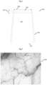
- FIG 1 A typical protective cap 100 for a camera for examining microcirculation is shown.
- the camera for example the CytoCam® from Braedius, is inserted into the hollow interior 106 of the protective cap 100 and can thus be kept sterile during an examination of the microcirculation in a patient's oral cavity.
- the usual protective cap 100 is made of a plastic and has a conical shape.
- the rear end 112 of the protective cap, through which the camera can be inserted into the interior 106 of the protective cap, is open.
- the lateral surface 102 is adjoined by a front side 104 which is made of a transparent material so that the microcirculation can be observed through the front side 104 using the camera.
- the front side 104 can be round in top view and essentially have a diameter 108 of about 9 mm.
- the thickness 110 of the layer forming the front side 104 is approximately 1 mm.
- figure 2 12 is a snapshot 200 which shows an image of the sublingual microcirculation as it can be recorded with a camera set up for this purpose (with the protective cap put on).
- the image was generated by illuminating the tissue with green light at 525 nm, which is almost completely absorbed by hemoglobin. Therefore, blood-carrying structures appear black in this representation.
- the microcirculation can be made visible, for example, by means of reflected-light dark-field imaging, which is shown below using the figure 3 is to be explained (figure comes from van parent HA; Journal of Clinical Monitoring and Computing; 2015 October; 29(5):543-8 ).
- a suitably configured camera can be used for this purpose, which figure 3 is represented by a lens 302 .
- the pen-shaped camera is also surrounded by a protective cap 300 in FIG.
- the protective cap 300 can be the in figure 1 Act protective cap shown.
- the camera is equipped with additional light sources 304, eg green LEDs, which illuminate the tissue 310 with which the protective cap 300 is brought into contact. When using green light, hemoglobin appears black because it has a broad absorption spectrum around 525 nm.
- pressure artifacts represent a significant problem when examining the microcirculation.
- the fine superficial capillaries 312 can be squeezed, which can lead to a false representation of the microcirculation and ultimately to an incorrect diagnosis.
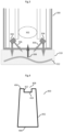
- FIG 4 a schematic side view of a basic form of the protective cap 400 according to the invention is shown.
- the protective cap 400 according to various exemplary embodiments also has an elongated shape, which can correspond to a cylinder or a truncated cone, for example.
- the protective cap body essentially has a lateral surface 402 and an end face 404 as well as an open rear end 406.
- the protective cap 400 according to the invention has a recess 408 in the end face 404.
- the indentation 408 can be present, for example, centered in the circular end face 404 (viewed in plan view).
- the recess 408 has a side wall or wall 412 which extends to the bottom 410 of the recess 408 .
- the geometric configuration of the end face 404 together with the recess 408 can be varied. In the example shown in figure 4 the corners at the transition from the lateral surface 402 to the end face 404 and at the transition from the end face 404 to the wall 412 of the depression 408 are pointed or angular. Any of these transitions can however, also be rounded (regardless of the respective other transition). Furthermore, the angles at the transitions between the surfaces mentioned in figure 4 are approximately 90° in a first approximation, be set up differently.
- the end face 404 does not have to be flat, but can have a structure or rise or fall towards the edge of the depression 408 .
- at least part of the base 410 and optionally at least part of the wall 412 and at least part of the end face 404 can be made of a transparent material. This ensures that the camera located inside the protective cap 400 can image the observed tissue and, if required, additional light can be radiated from the protective cap 400 into the tissue.
- the ratio between the size of the opening of the recess 408 and the size of the face 404 can also be varied as needed.
- FIG. 4 The cross-sectional view shown is merely a schematic representation of the protective cap according to the invention and the relationships of the individual components to one another can be adapted in many ways. However, all of the embodiments have in common that a depression 408 is arranged in the end face 404, whereby the area of the tissue observed by means of the camera is not in contact with the protective cap 400 during an examination of the microcirculation, but is pressure-free because of the depression 408.
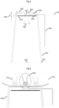
- FIG. 5 Another protective cap 500 according to various exemplary embodiments is in figure 5 shown. Items already related to figure 4 have been explained will not be described again.
- the bottom 410 of the depression is formed as a small plate made of transparent material resting on the rear side of the end face 404 .
- the small material plate can be permanently fastened to the rear of the end face or can be detachably fixed (in the sense of exchangeable) by means of appropriate holding mechanisms.
- the exchange of the small base plate 410 can take place via the open rear end 406 of the protective cap 500 .
- FIG. 5 Another element is shown which can be provided independently of all other freely adjustable features of the cap according to the invention, namely a channel 502.
- a channel 502. Although only one channel 502 is shown, it is representative of a number of channels which can be seen in the material layer under the end face 404 can be arranged.
- the channel 502 has a first opening which opens into the wall 412 of the depression 408 .
- the channel 502 also has a second opening, which is arranged in the lateral surface 402 .
- a line 504 is also connected to the second opening of the channel 502 .
- the (at least one) channel 502 can be used to create a negative pressure in the cavity 408, to introduce a fluid into the cavity 408 or to suck unwanted material out of the cavity 408.
- the openings of a channel need not be in a 1:1 relationship to channel 502. This means that a channel can branch out, for example, and the opening in the lateral surface 402 can be in contact with a plurality of openings in the wall 412 of the depression 408 .
- the channel 502 can (additionally or exclusively) have at least one opening arranged in the face 404 . This can be advantageous, for example, if the tissue arranged around the depression 408 is to be sucked in and/or fixed during an examination by means of negative pressure.
- the position of the second opening in the lateral surface 402 is also arbitrary. So it can deviate from the in figure 5 position shown further to the open rear end 406 of the protective cap 500 can be arranged.
- the second opening can also be arranged in the edge 510 of the jacket surface 402 , in which case the channel 502 can then be integrated in the jacket of the protective cap 500 .
- Such an arrangement can have the advantage that the connected line 502 can be shorter, its detachment from the opening is less likely and that the corresponding protective cap without a laterally protruding line 504 is more compact and can thus penetrate into small gaps and corners in the examined tissue .
- the effect that has the deepening of the protective cap according to the invention when examining the microcirculation in the tissue is based on the figure 6 be clarified.
- the figure shows, on the one hand, a tissue layer 310 including the capillaries 312 or capillary loops present therein, as well as a protective cap 500 in contact with this tissue layer 310, in which a camera is located (in figure 6 not shown explicitly).
- the illustration shows that the area of the tissue 310 on which the protective cap 500 rests with the end face 404 is compressed and as a result the blood flow through the corresponding capillaries 312 can be impeded (becomes discontinuous).
- the space of the depression 408 can be filled (by means of the channel 502) with optically transparent liquid medium or air, for example.
- the space of the depression 408 can be filled (by means of the channel 502) with optically transparent liquid medium or air, for example.
- the microcirculation is examined under the influence of a variable pressure disturbance and the state of health of the patient can thus be inferred.
- the depression 408 can be subjected to a predefined pressure by supplying air, and after this predefined pressure has been released, the time after which the microcirculation returns to its original state can be measured.
- the present protective cap is ideally suited for carrying out these and other types of dynamic measurements, since it creates an interface between the tissue 310 and the protective cap, at which on the one hand a pressure-free area (in the sense of compression of the tissue 312) is provided and on the other hand For examination purposes, a predefined pressure can be exerted on the tissue 312 by the targeted introduction of fluids (e.g. immersion oil) or air.
- fluids e.g. immersion oil
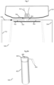
- FIG 7 Another embodiment of the protective cap 500 is shown, with only its front part being shown.
- the protective cap 500 has two channels, a first channel 502 and a second channel 702, both channels being able to be of the same type and being functionally interchangeable. Otherwise the in figure 7 Protective cap shown, for example, in figure 5 correspond to the protective cap shown.
- unwanted material 704 such as detritus (including remains of red blood cells), saliva or small air bubbles often obstruct the view of the microcirculation.
- the depression 408 can be flushed with a suitable liquid by means of the first channel 502, which can be used as a flushing channel.
- the unwanted material 704 can then be flushed out of the depression 408 and transported away from the observation area of the camera along the point of contact between the tissue 310 and the face 404 of the protective cap 500 (first flushing path 706).
- the Face is structured and has corresponding furrows or the like to facilitate the removal of unwanted material.
- a second channel 702 (or also several) can be provided, through which the introduced liquid together with the undesired material 704 can be transported out of the depression 408 (second flushing path 708).
- a line 712 can optionally be connected to the second channel 702, via which the second channel 702 can be subjected to suction in order to actively suck off the unwanted material 704 from the depression 408.
- the second channel 702 can open into the lateral surface 402 of the protective cap (ie without an extension line 712 to a suction pump) and serve to allow the undesired material to flow out of the depression 408 .
- Figures 8A-8D a 3D representation of the protective cap according to further exemplary embodiments is shown, where Figure 8A shows a spatial representation of an assembled form of the protective cap 500, while Figures 8B-8D Show exploded views from different angles.
- the reference numbers are based on the previous figures, so that elements of the cap according to the invention that have already been described will not be described again.
- the tip of the protective cap 500 i.e. essentially a part of the protective cap 500 which has the end face 404 and an area of the lateral surface 402 adjoining it (hereinafter referred to as the upper part), is separated from the remaining part, which comprises the remaining Has part of the lateral surface 402 (hereinafter referred to as the lower part), is detachable.
- the base 410 can be inserted particularly easily or an existing base 410 can be changed.
- the floor 410 can be inserted into the top or placed on the rim 806 of a raised dock 802 .
- the upper and lower parts After the upper and lower parts have been plugged together, pressure from the raised web 802 on the base 410 fixes the base 410 in its position.
- the upper part rests with its lower edge on a step 804 in the lower part.
- the upper part can be connected to the lower part just as well via a screw connection.
Landscapes
- Health & Medical Sciences (AREA)
- Life Sciences & Earth Sciences (AREA)
- Surgery (AREA)
- Physics & Mathematics (AREA)
- Veterinary Medicine (AREA)
- Public Health (AREA)
- Animal Behavior & Ethology (AREA)
- General Health & Medical Sciences (AREA)
- Optics & Photonics (AREA)
- Pathology (AREA)
- Biophysics (AREA)
- Engineering & Computer Science (AREA)
- Biomedical Technology (AREA)
- Heart & Thoracic Surgery (AREA)
- Medical Informatics (AREA)
- Molecular Biology (AREA)
- Radiology & Medical Imaging (AREA)
- Nuclear Medicine, Radiotherapy & Molecular Imaging (AREA)
- Dentistry (AREA)
- Oral & Maxillofacial Surgery (AREA)
- Spectroscopy & Molecular Physics (AREA)
- Audiology, Speech & Language Pathology (AREA)
- Epidemiology (AREA)
- Astronomy & Astrophysics (AREA)
- General Physics & Mathematics (AREA)
- Infusion, Injection, And Reservoir Apparatuses (AREA)
- Endoscopes (AREA)
- Investigating Or Analysing Materials By Optical Means (AREA)
Description
- Bei der vorliegenden Vorrichtung handelt es sich um eine Schutzkappe für eine bildgebende Vorrichtung, insbesondere um eine Schutzkappe für eine Kamera zur Beobachtung einer Mikrozirkulation, beispielsweise im Mundraum eines Patienten.
- Die lebensbedrohlichen Krankheiten intensivmedizinischer Patienten sind häufig begleitet von Änderungen in der Mikrozirkulation (auch mikrovaskuläre Perfusion genannt). Die Mikrozirkulation wird zunehmend als kritische Determinante der Organfunktion intensivmedizinischer Krankheitsbilder angesehen. In den letzten Jahren sind daher neue Methoden für die Visualisierung der Mikrozirkulation entwickelt worden, wie zum Beispiel das sidestream darkfield imaging (abgekürzt SDF, auf Deutsch: Seitenstrom-Dunkelfeld-Bildgebung) oder incident darkfield illumination imaging (abgekürzt IDF, auf Deutsch Auflicht-Dunkelfeld-Bildgebung). Durch diese Methoden ist mittels entsprechender Untersuchungsgeräte eine direkte Beobachtung der Mikrozirkulation am Patientenbett möglich. Die Untersuchung der Mikrozirkulation erfolgt zurzeit vor allem im Rahmen der universitären Medizin. Die direkte Untersuchung der Mikrozirkulation ist ein wertvolles diagnostisches Werkzeug und kann dabei helfen, das Krankheitsstadium eines intensivmedizinischen Patienten besser einzuschätzen. Es kann angenommen werden, dass in den nächsten Jahren Therapieentscheidungen auf der Basis von mikrozirkulatorischen Parametern erfolgen werden.
- In der Regel wird im Rahmen der oben genannten Methoden die Mikrozirkulation der Patienten durch Einführen einer kleinen stiftförmigen Kamera in den Mund untersucht, wobei die Kameraspitze unter die Zunge (sublingual) platziert wird. Die Kamera ist dabei von einer durchsichtigen keimarmen Schutzkappe bedeckt, welche aus hygienischen Gründen jeweils nach erfolgter Untersuchung eines Patienten von der Kamera gelöst und entsorgt wird. Zur Untersuchung eines nächsten Patienten wird auf die Kamera eine unbenutzte Schutzkappe aufgesetzt. In diesem Zusammenhang sei hier beispielhaft die CytoCam® der Firma Braedius erwähnt. Dabei handelt es sich um eine Kamera zur Beobachtung der Mikrozirkulation der Firma Braedius, welche auf der Auflicht-Dunkelfeld-Bildgebung basiert und sich bestens zur direkten Visualisierung der sublingualen Mikrozirkulation eignet. Auch bei dieser Kamera kommen die beschrieben Einweg-Schutzkappen zum Einsatz.
- Generell erfolgt die Beobachtung der sublingualen Mikrozirkulation, indem eine mit einer Schutzkappe geschützte Kamera an die sublinguale Schleimhaut angelegt bzw. in Kontakt mit dieser gebracht wird. Hierdurch können die unter der Schleimhautoberfläche liegenden Haargefäße (Kapillaren) dargestellt werden.
- Ein wesentliches Problem bei der Untersuchung der Mikrozirkulation stellt der geringe intraluminale Druck in den Kapillaren dar. Beim Aufsetzten der Kamera auf die sublinguale Schleimhaut können die Kapillaren bereits durch den Druck auf die sublinguale Schleimhaut abgedrückt werden, welcher durch das Anlegen der Kamera erzeugt wird. Dies kann mitunter eine schlechte Perfusion der Mikrozirkulation suggerieren, obwohl eigentlich keine Störung der mikrovaskulären Perfusion vorliegt. Dieser Umstand wird auch mit dem Terminus Druckartefakt bezeichnet und kann letztendlich zu einer Falschdiagnose bezüglich des Gesundheitszustandes eines intensivmedizinischen Patienten und damit zu höchstwahrscheinlich für den Patienten nachteiligen Therapieentscheidungen führen.
- Ein weiteres Problem bei der Untersuchung der Mikrozirkulation stellt das Vorhandensein von übermäßigem Speichel, Zelltrümmern (u.a. von roten Blutkörperchen) oder Luftblasen am Zungenboden dar. Das Vorliegen dieser Materialien im Untersuchungsbereich erschwert die Untersuchung der Mikrozirkulation erheblich und kann mitunter die Untersuchung der Mikrozirkulation sogar unmöglich machen.
- Dokument
US 2006/0184037 A1 offenbart eine Schutzkappe gemäß dem Oberbegriff von Anspruch 1. - Ziel der vorliegenden Erfindung ist es, die oben genannten Probleme bei der Untersuchung der Mikrozirkulation zu umgehen. Diese Probleme werden durch die Vorrichtung gemäß Anspruch 1 gelöst. Weitere bevorzugte Ausführungsformen sind in den Unteransprüchen beschrieben.
- Bevor die Erfindung genauer erläutert wird, soll zunächst eine aus dem Stand der Technik bekannte Schutzkappe für bildgebende Vorrichtungen zur Untersuchung der Mikrozirkulation kurz beschrieben werden. Eine solche beispielhafte Schutzkappe ist schematisch in
Figur 1 dargestellt und wird später im Detail beschrieben. Die Schutzkappen der derzeit erhältlichen Kameras zur Beobachtung der Mikrozirkulation bestehen aus einem durchsichtigen Kunststoff, durch den hindurch mittels der Kamera die Mikrozirkulation beobachtet werden kann. Bedingt durch die stiftförmige Form der Kamera sind gattungsgemäße Schutzkappen im Wesentlichen ebenfalls stiftförmig oder konisch geformt, so dass der stiftförmige Teil der Kamera, an dessen Ende sich die Optik befindet, in die Schutzkappe eingesetzt werden kann. Die gattungsgemäße Schutzkappe ist starr und aus einem ca. 1 mm dicken durchsichtigen Kunststoff gefertigt. Die Schutzkappe wird vor der Untersuchung über das stabförmige Ende der Kamera gesteckt und schließt am Kamerakörper dicht ab. Zur Beobachtung der Mikrozirkulation wird die Schutzkappe direkt auf die Schleimhaut aufgesetzt. Die Kontaktfläche der Schutzkappe mit der Schleimhaut besteht aus einer planen Fläche. - Ausgehend von dieser Situation liegt der Erfindung die Aufgabe zu Grunde, die Untersuchung der Mikrozirkulation zu verbessern, insbesondere das Auftreten von Druckartefakten zu unterbinden und im Weiteren die Abbildungsqualität zu verbessern, welche durch übermäßigen Speichel, Zelltrümmern und/oder Luftblasen, beeinträchtigt sein kann.
- Bei der erfindungsgemäßen Vorrichtung handelt es sich um eine Schutzkappe für eine bildgebende Vorrichtung, welche einen hohlen Schutzkappenkörper mit einer Stirnfläche, einer Mantelfläche und einem offenen hinteren Ende aufweist, durch welches die bildgebende Vorrichtung in die Schutzkappe eingesetzt werden kann, und eine Vertiefung, welche in der Stirnfläche angeordnet ist. Die Schutzkappe weist ferner mindestens einen Kanal auf, welcher im vorderen Teil des Schutzkappenkörpers unter der Stirnfläche angeordnet ist, wobei der mindestens eine Kanal eine erste Öffnung aufweist, welche in der Seitenwand der Vertiefung angeordnet ist, und eine zweite Öffnung aufweist, welche bevorzugt in der Mantelfläche des Schutzkappenkörpers angeordnet ist.
- Abweichend zu bisher bekannten Schutzkappen, welche wie eingangs erwähnt eine durchgehend plane Stirnseite aufweisen, ist die erfindungsgemäße Schutzkappe dahingehend modifiziert, dass sie eine Vertiefung (Aussparung) in der Stirnfläche aufweist. Diese Modifikation ermöglicht es, Druckartefakte im Untersuchungsbereich zu reduzieren oder sogar ganz zu vermeiden. Bei gattungsgemäßen Schutzkappen wird an Stellen, an denen die Schutzkappe auf die Schleimhaut aufgesetzt wird, Druck auf die betroffene Schleimhaut ausgeübt. Dieser Druck führt zur Kompression oberflächlicher Kapillarschlingen, wodurch der Fluss in den in dem komprimierten Bereich vorliegenden Kapillaren behindert wird und diskontinuierlich wird; es kommt zur Bildung von Druckartefakten. Bei der Schutzkappe gemäß verschiedenen Ausführungsbeispielen ist in der Stirnfläche des Schutzkappenkörpers, beispielsweise in der Mitte des Bereichs, welcher während der Untersuchung in Kontakt mit der Schleimhaut steht, eine Vertiefung eingearbeitet. Dadurch kann die in diesem Bereich erfolgende Untersuchung der Mikrozirkulation (z.B. durch Videoaufnahme der Mikrozirkulation) ohne Druckartefakte erfolgen.
- Die erfindungsgemäße Schutzkappe kann eine längliche bzw. stiftförmige Form aufweisen, beispielsweise die Form eines stumpfen Kegels, wobei die Deckfläche der Stirnfläche entspricht und die Grundfläche dem offenen Ende des Schutzkappenkörpers entspricht. Die Form der Schutzkappe kann insgesamt an die Form des Teils der bildgebenden Vorrichtung angepasst sein, den sie abdecken soll. Bei der bildgebenden Vorrichtung kann es sich um eine beliebige Kamera handeln, die zur Beobachtung der Mikrozirkulation geeignet ist. Beispielsweise kann es sich dabei um die CytoCam® der Firma Braedius handeln. Die erfindungsgemäße Schutzkappe kann aus einem beliebigen geeigneten Material hergestellt sein, etwa einem Kunststoff, und kann beispielsweise durch Sintern oder 3D-Druck gefertigt werden.
- Die erfindungsgemäße Schutzkappe weist in der Vertiefung einen Boden auf. Mit anderen Worten handelt es sich bei der Vertiefung um eine gegen den im Inneren des Schutzkappenkörpers liegenden Hohlraum verschlossene Vertiefung oder Ausnehmung. Dabei schließt der Boden die Vertiefung gegenüber dem innenliegenden Hohlraum des Schutzkappenkörpers dicht (fluiddicht), so dass Fluide oder sonstiges Materie nicht durch die Vertiefung hindurch in den Hohlraum der Schutzkappe gelangen kann. Der innenliegende Hohlraum der Schutzkappe, in dem bei einer Untersuchung des Patienten eine Kamera eingesetzt ist, kann somit steril gehalten werden.
- Der Boden der erfindungsgemäßen Schutzkappe weist ein transparentes Material auf, beispielsweise ein Deckglas. Der Boden der Vertiefung kann integraler Bestandteil der gesamten Schutzkappe sein. Alternativ kann der Boden der Vertiefung nicht integral mit der Vertiefung ausgebildet sein. Der Boden der Vertiefung kann auch aus einem anderen Material als dem der Schutzkappe ausgebildet sein. Insbesondere kann der Boden ein Deckglas oder ein anderes Plättchen aus einem lichtdurchlässigen Material aufweisen. Dabei kann das den Boden ausbildende Material beispielsweise durch das offene Ende des Hohlraums in diesen eingebracht werden und an dem unteren Rand der Vertiefung und/oder im Bereich der Rückseite der Stirnfläche befestigt werden, etwa durch einen entsprechend dafür vorgesehenen Click-Mechanismus.
- Im Hinblick auf den Boden der Vertiefung kann dieser gemäß weiteren Ausführungsbeispielen der Schutzkappe ein optisches Element aufweisen. Der Boden der Vertiefung kann aus einem transparenten Material geformt sein und als ein optisches Element eingerichtet sein. Beispielsweise kann das optische Element ein optischer Filter, eine Linse, eine Blende oder eine beliebige Kombination daraus sein. Allgemein kann es sich bei dem optischen Element um ein beliebiges zweckdienliches optisches Element handeln, welches an der Gestaltung des Lichtpfades vom Gewebe des untersuchten Patienten zu der in der Schutzkappe vorliegenden Kamera mitwirkt. Um ein konkretes Ausführungsbeispiel zu nennen, kann der Boden der Vertiefung über elektrische Anschlüsse verfügen und aus abdunkelbarem Glas bestehen und damit als eine variable Blende eingerichtet sein. Zusätzlich kann ein optischer Filter vorgesehen sein, welcher vor oder hinter der Blende angeordnet ist. Im Rahmen dieser Anmeldung ist die Beziehung zwischen dem Boden der Vertiefung und dem optischen Element weit zu sehen. Das heißt, dass das optische Element (oder mehrere optische Elemente) als ein Modul (als Module) eingerichtet sein kann (können) und mit einem Element, welches den physischen Boden der Vertiefung ausbildet (also die Materialschicht, welche die Vertiefung gegenüber dem Hohlraum dicht abschließt) gekoppelt sein kann (können). Es kann jedoch auch sein, dass das optische Element unmittelbar in der Materialschicht integriert ist, die den Boden der Vertiefung bildet.
- Gemäß weiteren Ausführungsbeispielen der Schutzkappe kann an der Innenseite des Schutzkappenkörpers im Bereich der Stirnfläche mindestens ein Halteelement angeordnet sein, welches zur lösbaren Befestigung des Bodens der Vertiefung eingerichtet ist. Unter dem Bereich der Stirnfläche der Schutzkappe kann die Stirnfläche der Schutzkappe sowie der daran anliegende Bereich der Schutzkappe gemeint sein, also etwa die vordere Spitze der Schutzkappe, beispielsweise etwa das vordere Fünftel der Schutzkappe. Anders ausgedrückt kann die erfindungsgemäße Schutzkappe so eingerichtet sein, dass der Boden der Vertiefung als ein austauschbares Modul eingerichtet ist und beispielsweise durch das offene hintere Ende der Schutzkappe eingesetzt bzw. ausgetauscht werden kann. Das Halteelement kann beispielsweise als eine Ringnut eingerichtet sein, welche in der Innenwand des Hohlraums angeordnet ist. Dabei kann die Schutzkappe aus zwei Teilen bestehen, die gegeneinander verschraubt oder aneinander gesteckt werden können, wobei ein erster (z.B. oberer) Teil der Ringnut in dem ersten (z.B. oberen) Teil der Schutzkappe bereitgestellt ist und ein zweiter (z.B. unterer) Teil der Ringnut in dem zweiten (z.B. unteren) Teil der Schutzkappe bereitgestellt ist. Der Boden der Vertiefung kann vor dem Verschrauben bzw. Zusammenstecken der beiden Schutzkappenteile miteinander zwischen diese beiden eingesetzt werden.
- Gemäß weiteren Ausführungsbeispielen kann die Stirnfläche des Schutzkappenkörpers um die Vertiefung herum plan ausgebildet sein. Dabei kann die Ebene der Stirnfläche parallel zur Ebene des Bodens der Vertiefung angeordnet sein. Zusätzlich optional kann der Winkel, unter dem die Mantelfläche auf die Stirnfläche in jedem Punkt entlang des äußeren Randes der Stirnfläche trifft, in etwa 90° oder mehr betragen. Je größer dieser Winkel, umso ausgeprägter die Kegelnatur der Schutzkappe gegenüber einem Zylinder. In analoger Weise kann auch der Winkel zwischen der Stirnfläche und der Wandung der Vertiefung in etwa 90° oder mehr betragen. Anders ausgedrückt kann die Stirnfläche um bis zu 90° nach unten umknicken und so die Wandung der Vertiefung ausbilden, die bis zum Boden der Vertiefung führt. Der Übergang zwischen Mantelfläche und Stirnfläche kann eine scharfe Kante oder eine gerundete Kante bilden. Der Übergang zwischen Stirnfläche und Wandung der Vertiefung kann in analoger Weise eine scharfe Kante oder eine gerundete Kante bilden. Die Aussage, dass um die Vertiefung herum die Stirnfläche des Schutzkappenkörpers plan ausgebildet ist kann, kann damit den Großteil der Stirnfläche betreffen, wobei der in der Stirnfläche liegende Randbereich der Vertiefung und/oder der Bereich des äußeren Randes der Stirnfläche davon ausgenommen sein können.
- Gemäß weiteren Ausführungsbeispielen kann die Stirnfläche des Schutzkappenkörpers als eine radial zur Vertiefung hin ansteigende oder abfallende Oberfläche ausgebildet sein. Das heißt, dass der Außenrand der Stirnfläche, an dem die Stirnfläche in die Mantelfläche übergeht, in einer Querschnittsseitenansicht betrachtet tiefer oder höher liegen kann. Die ansteigende oder abfallende Eigenschaft der Stirnfläche muss nicht notwendigerweise strikt für jeden Bereich/Abschnitt der Stirnfläche gelten sondern ist als eine Aussage bezüglich des durchschnittlichen Verhaltens der Stirnfläche zu sehen. So kann es etwa sein, dass die Stirnfläche stufenartig oder anderweitig segmentiert zwar gesamt gesehen zur Öffnung der Vertiefung (Vertiefungsöffnung) hin ansteigt oder abfällt, aber in einigen Abschnitten plan verläuft (also weder ansteigend noch abfallend) oder sogar die zum Gesamtverhalten entgegengesetzte Steigung aufweist. Mit einer Ausführungsform der Schutzkappe mit einer radial zur Vertiefung hin abfallenden Stirnfläche und einem abgerundeten Rand an der Vertiefungsöffnung können Druckartefakte weiträumig um die unmittelbar untersuchte Gewebestelle vermieden werden. Zugleich jedoch kann ein am Gewebe anliegender Außenrand der Stirnfläche dafür sorgen, dass kein Streulicht von außen in die Vertiefung und damit letztendlich zur bildgebenden Vorrichtung gelangen kann.
- Gemäß weiteren Ausführungsbeispielen kann die Stirnfläche des Schutzkappenkörpers zumindest in einem Bereich um die Vertiefung herum strukturiert sein. Der Bereich kann beliebig geformt sein, etwa konzentrisch oder elliptisch, und er kann symmetrisch oder asymmetrisch um die Vertiefungsöffnung angeordnet sein. Der Bereich kann sich auch über die gesamte Stirnfläche ausdehnen. Bei der Strukturierung kann es sich um eine beliebige zweckdienliche Strukturierung handeln, wie etwa eine genoppte oder geriffelte Strukturierung. Die Strukturierung kann funktionale Materialien aufweisen, d.h. Materialien, die z.B. eine verbesserte Griffigkeit gegenüber dem untersuchten Gewebe aufweisen (z.B. Mini-Saugglocken oder Mini-Saugnäpfe) oder spezielle optische (z.B. reflektierende) Eigenschaften haben. Die Strukturierung kann ebenfalls dahingehend funktional sein, als dass sie den Abtransport von übermäßigem Speichel, Zelltrümmern oder Luftblasen unterstützt. Beispielsweise kann gemäß weiteren Ausführungsbeispielen der Schutzkappe in der Stirnfläche des Schutzkappenkörpers mindestens eine Furche angeordnet sein, welche sich zwischen der Vertiefung und dem äußeren Rand der Stirnfläche erstreckt. Die mindestens eine Furche kann als Transportkanal verwendet werden, um beispielsweise das eben erwähnte unerwünschte Material aus dem Untersuchungs-/Beobachtungsbereich, welcher im Wesentlichen der Vertiefungsöffnung entspricht, abzutransportieren.
- Gemäß der Erfindung weist die Schutzkappe mindestens einen Kanal auf, welcher im vorderen Teil des Schutzkappenkörpers unter der Stirnfläche verläuft. Der erste Kanal weist eine erste Öffnung auf, welche in der Seitenwand der Vertiefung oder in der Stirnfläche mündet oder angeordnet ist. Zusätzlich weist der Kanal teine zweite Öffnung auf, welche in der Mantelfläche des Schutzkappenkörpers angeordnet ist. Der Kanal kann zum einen die Rolle der oben erwähnten Furche übernehmen und zum Abtransport von unerwünschtem Material aus dem Untersuchungs-/Beobachtungsbereich dienen. Durch die erste Öffnung, welche in der Wandung der Vertiefung münden kann, kann das Material in den Kanal eintreten. Um das unerwünschte Material aktiv abzusaugen, kann dazu an der zweiten Öffnung des Kanals eine Leitung angeschlossen sein, mittels welcher in dem Kanal ein Unterdruck erzeugt werden kann. Andererseits kann der mindestens eine Kanal auch als Zuleitung fungieren und beispielsweise zum Einbringen von Luft oder flüssigen, bevorzugt transparenten Medien in die Vertiefung verwendet werden. Hierbei erfüllt der mindestens eine Kanal die Rolle eines Spülkanals. Durch Einbringen einer optisch aktiven Substanz (z.B. eines Immersionsöls) in die Vertiefung kann die erzielbare Auflösung des während einer Patientenuntersuchung aufgenommenen Bildes gesteigert werden. Andererseits kann der mindestens eine Kanal mindestens eine Öffnung aufweisen, welche in der Stirnfläche mündet, beispielsweise in einem Bereich der Stirnfläche um die Vertiefung herum. Durch Bereitstellen eines Unterdrucks in dem mindestens einen Kanal kann dieser Unterdruck an der mindestens einen Öffnung dafür sorgen, dass an der Öffnung anliegendes Gewebe angesaugt und somit fixiert wird. Der mindestens eine Kanal kann also vielfältige Funktionen erfüllen, wobei diverse Parameter wie seine Bemaßung, sein Verlauf, die Anzahl und Lageort der Öffnungen an die beabsichtigte Verwendung angepasst werden können. Insgesamt sind natürlich auch Ausführungsbeispiele der Schutzkappe mit mehreren Kanälen im Rahmen der Erfindung enthalten, wobei die eben beschriebenen Arten der Kanäle in einer beliebigen Kombination in ein und derselben Schutzkappe vorkommen können. So kann zum Beispiel unter den im vorderen Teil der Schutzkappe verlaufenden Kanälen mindestens ein Kanal als Spülkanal und mindestens ein weiterer Kanal als Zuleitung dienen. Generell kann es von Vorteil sein, wenn die Öffnung des als Leitung zum Abtransport von unerwünschtem Material fungierenden Kanals der Öffnung des als Spülkanal fungierenden Kanals im Wesentlichen gegenüber angeordnet ist, beispielsweise diametral gegenüber angeordnet ist.
- Bei der Verwendung des Kanals als Zuleitung kann als flüssiges transparentes Medium eine viskose Flüssigkeit in die Vertiefung eingebracht werden. Die Einleitung des flüssigen Mediums in die Vertiefung kann kontinuierlich oder bolusweise erfolgen, beispielsweise mittels einer Spritze oder Pumpe, die an den mindestens einen Kanal angeschlossen werden kann. Mindestens ein weiter Kanal oder mindestens eine oben erwähnte Furche kann verwendet werden zum Abtransport von Material aus der Vertiefung, wobei es sich bei dem Material um Detritus und/oder Speichel bzw. das vom Speichel verdünnte flüssige Medium, etwa das viskose Gel, handeln kann. Dazu kann an die außenliegende Öffnung des Abtransportkanals eine Spritze oder eine Pumpe angekoppelt werden und der Absaugvorgang kann kontinuierlich oder intermittierend erfolgen. Bei Verwendung eines Abtransportkanals kann dessen Durchmesser größer ausfallen als der Durchmesser des für die Einleitung des flüssigen Mediums verwendeten Kanals, um das Risiko einer Verstopfung bzw. Blockierung des Abtransportkanals zu minimieren.
- Das Einleiten eines Mediums in die Vertiefung kann zudem vorteilhaft sein, insbesondere eines viskosen Gels, da es einen leichten Gegendruck auf das beobachtete Gewebe (d.h. das Gewebe im Bereich der Vertiefung) aufbauen kann. Dadurch kann verhindert werden, dass das Gewebe im Beobachtungsbereich (d.h. im Bereich der Vertiefung der Schutzkappe) nicht in die Vertiefung "fällt" bzw. expandiert und damit im Randbereich der Vertiefung Kapillaren in dem Gewebe abgedrückt werden. Mit anderen Worten kann das in die Vertiefung eingebrachte flüssige Medium dafür sorgen, dass das im Bereich der Vertiefung angeordnete Gewebe sich nur leicht in die Richtung der Vertiefung wölbt. Um zu verhindern, dass das in die Vertiefung eingeleitete Medium keinen zu großen Gegendruck aufbaut, können in der Stirnfläche der Kappe, wie oben erwähnt, Nuten bzw. Furchen und/oder weitere Kanäle angeordnet sein, die von der Vertiefung radial nach außen zum Mantelbereich der Schutzkappe verlaufen und so ein Abließen des flüssigen Medium, etwa des viskosen Gels, erlauben. Die Dimension der für den Druckabbau bereitgestellten Nuten und/oder Kanäle kann an das flüssige Medium angepasst werden, etwa an seine Viskosität, und so dessen kontrolliertes Abließen mit einer vorbestimmten Rate ermöglichen.
- Das Einleiten des flüssigen Mediums in die Vertiefung während einer erfolgenden Untersuchung kann zudem für eine aktive Befeuchtung der untersuchten Schleimhaut sorgen, welche insbesondere bei Intensivpatienten häufig sehr trocken ist. Zugleich kann das flüssige und bevorzugt viskose Medium einen Gleitfilm auf der Schleimhaut ausbilden und so die Gleiteigenschaft der Schutzkappe auf der Schleimhaut verbessern, was Verletzungen der Schleimhaut vorbeugen kann. Zusätzlich kann das flüssige Medium in der Vertiefung eine ansonsten an der Grenzfläche zwischen Luft und feuchter Schleimhaut auftretende Reflexionen vermindern bzw. verhindern, welche die Beobachtung der Schleimhaut durch die Schutzkappe hindurch stören kann.
- Bei dem verwendeten flüssigen viskosen Medium kann es sich beispielsweise um aus der Augenheilkunde bekannte hochviskose Flüssigkeiten auf Grundlage von Hyaluronaten (z.B. MICROVISC® Natrimhyaluronat 1%) oder Hydroxypropylmethylcellulose (z.B. POLYVISC® 2%) handeln.
- Gemäß weiteren Ausführungsbeispielen der Schutzkappe kann die Seitenwand der Vertiefung und/oder die Stirnfläche der Schutzkappe ein lichtundurchlässiges (transpatentes) Material aufweisen. Mit der Seitenwand der Vertiefung ist generell die von der Stirnfläche aus im Wesentlichen nach unten verlaufende Wandung gemeint, die sich bis zum Boden der Vertiefung erstreckt. Das Bereitstellen von lichtdurchlässigem Material in den genannten Bereichen kann gewährleisten, dass maximal viel Licht aus dem untersuchten Bereich des Gewebes zum Objektiv der Kamera gelangt. Um zu verhindern, dass hingegen kein störendes Streulicht von der Umgebung des untersuchten Gewebebereiches zum Objektiv der Kamera gelangt, kann die Mantelfläche aus einem lichtundurchlässigen Material gefertigt sein.
- Gemäß weiteren Ausführungsbeispielen kann in einem weiteren Kanal ein Lichtwellenleiter angeordnet sein. Dieser Kanal kann damit zur Lichtführung verwendet werden, wobei das Licht aus einer externen Lichtquelle in den Lichtwellenleiter eingekoppelt werden kann und mittels des Lichtwellenleiters an die gewünschte Stelle geführt werden kann. Über entsprechend positionierte Öffnungen kann der Lichtwellenleiter Licht an gewünschte Stellen der Schutzkappe geführt werden, um das untersuchte Gewebe zusätzlich auszuleuchten. Besonders bevorzugt kann hier Licht mit einer Wellenlänge (oder mehreren Wellenlängen) ins beobachtete/untersuchte Gewebe eingebracht werden, welche von der Wellenlänge, die von der Kamera verwendet wird, unterschiedlich ist. Das kann besonders nützlich sein, wenn man im beobachteten Gewebe nur bestimmte ausgewählte Strukturen mittels resonanter Anregung sichtbar machen will. Zur gezielten Sichtbarmachung der Mikrozirkulation, welche auf den Durchfluss von Blut und damit Hämoglobin zurückgeführt werden kann, kann grünes Licht mit einer Wellenlänge von 525 nm in das beobachtete Gewebe eingestrahlt werden.
- Weitere Vorteile und Merkmale der Erfindung ergeben sich aus den nachfolgenden beispielhaften Erläuterungen mit Bezug auf die Figuren. Die in den Figuren gezeigten und/oder nachfolgend erläuterten Merkmale können, unabhängig von konkreten Merkmalskombinationen, allgemeine Merkmale der Erfindung sein, die losgelöst von der hier erfolgten Darstellung auf andere Ausführungsbeispiele der Erfindung übertragbar sind.
-
Figur 1 zeigt eine gewöhnliche Schutzkappe für eine Kamera zur Untersuchung der Mikrozirkulation. -
Figur 2 zeigt eine Momentaufnahme, auf welcher ein Abbild der sublingualen Mikrozirkulation zu sehen ist. -
Figur 3 zeigt eine Möglichkeit der Visualisierung der Mikrozirkulation. -
Figur 4 zeigt eine schematische Seitenansicht einer Grundform der erfindungsgemäßen Schutzkappe. -
Figur 5 zeigt ein weiteres Ausführungsbeispiel der erfindungsgemäßen Schutzkappe. -
Figur 6 veranschaulicht den vorteilhaften Effekt der Vertiefung der erfindungsgemäßen Schutzkappe bei der Untersuchung der Mikrozirkulation. -
Figur 7 zeigt eine weitere Ausführungsform der Schutzkappe. -
Figuren 8A-8D zeigen 3D-Dartellung der Schutzkappe gemäß weiteren Ausführungsbeispielen. - In den nachfolgend beschriebenen Figuren werden gleiche Elemente, die in verschiedenen Figuren auftauchen, mit den gleichen Bezugszeichen versehen.
- In
Figur 1 ist eine gewöhnliche Schutzkappe 100 für eine Kamera zur Untersuchung der Mikrozirkulation gezeigt. Die Kamera, beispielweise die CytoCam® der Firma Braedius, wird in den hohlen Innenraum 106 der Schutzkappe 100 eingesetzt und kann so während einer Untersuchung der Mikrozirkulation im Mundraum eines Patienten steril gehalten werden. Die gewöhnliche Schutzkappe 100 ist aus einem Kunststoff gefertigt und ist konisch geformt. Das hintere Ende 112 der Schutzkappe, durch das die Kamera in das Innere 106 der Schutzkappe eingesetzt werden kann, ist offen. An die Mantelfläche 102 schließt sich eine Frontseite 104 an, welche aus einem transparenten Material gefertigt ist, so dass die Mikrozirkulation mittels der Kamera durch die Frontseite 104 beobachtet werden kann. Die Frontseite 104 kann in der Draufsicht rund ausgebildet sein und im Wesentlichen einen Durchmesser 108 von ca. 9 mm aufweisen. Die Dicke 110 der die Frontseite 104 ausbildenden Schicht beträgt ca. 1 mm. -
Figur 2 ist eine Momentaufnahme 200, welche ein Abbild der sublingualen Mikrozirkulation dargestellt, wie es mit einer dafür eingerichteten Kamera (samt aufgesetzter Schutzkappe) aufgenommen werden kann. Das Abbild wurde unter Ausleuchtung des Gewebes mit grünem Licht bei 525 nm erzeugt, welches vom Hämoglobin nahezu vollständig absorbiert wird. Daher erscheinen in dieser Darstellung blutdurchflossene Strukturen schwarz. - Die Mikrozirkulation kann beispielsweise mittels Auflicht-Dunkelfeld-Bildgebung sichtbar gemacht werden, die im Folgenden anhand der
Figur 3 erläutert werden soll (Figur stammt aus van Elteren HA; Journal of Clinical Monitoring and Computing; 2015 Oktober; 29(5):543-8). Dazu kann eine entsprechend eingerichtete Kamera verwendet werden, welche inFigur 3 durch eine Linse 302 repräsentiert ist. Wie dargestellt ist zudem die stiftförmige Kamera in von einer Schutzkappe 300 umgeben. Bei der Schutzkappe 300 kann es sich um die inFigur 1 dargestellte Schutzkappe handeln. Die Kamera ist mit zusätzlichen Lichtquellen 304 ausgestattet, z.B. mit grünen LEDs, welche das Gewebe 310 ausleuchten, mit dem die Schutzkappe 300 in Kontakt gebracht wird. Bei Verwendung von grünem Licht erscheint Hämoglobin schwarz, da es um 525 nm ein breites Absorptionsspektrum aufweist. Wie bereits erläutert, stellen Druckartefakte ein wesentliches Problem bei der Begutachtung der Mikrozirkulation dar. Durch Auflegen der Schutzkappe 300 auf das zu untersuchende Gewebe 310 können die feinen oberflächlich vorliegenden Kapillaren 312 abgedrückt werden, was zu einer verfälschten Darstellung der Mikrozirkulation führen kann und damit letzten Endes zu einer falschen Diagnose. - In
Figur 4 ist eine schematische Seitenansicht einer Grundform der erfindungsgemäßen Schutzkappe 400 dargestellt. Wie die aus dem Stand der Technik bekannte und inFigur 1 dargestellte gewöhnliche Schutzkappe 100 weist auch die Schutzkappe 400 gemäß verschiedenen Ausführungsbeispielen eine längliche Form auf, die beispielsweise einem Zylinder oder Kegelstumpf entsprechen kann. Der Schutzkappenkörper weist im Wesentlichen eine Mantelfläche 402 und eine Stirnfläche 404 auf sowie ein offenes hinteres Ende 406. Im Unterschied zu der bekannten gewöhnlichen Schutzkappe weist jedoch die erfindungsgemäße Schutzkappe 400 eine Vertiefung 408 in der Stirnfläche 404 auf. Die Vertiefung 408 kann dabei beispielsweise zentriert in der (in Draufsicht betrachtet) kreisrunden Stirnfläche 404 vorliegen. Die Vertiefung 408 weist eine Seitenwand bzw. eine Wandung 412 auf, welche sich bis zum Boden 410 der Vertiefung 408 erstreckt. Die geometrische Ausgestaltung der Stirnfläche 404 samt der Vertiefung 408 kann vielfältig ausfallen. In der dargestellten beispielhaften Darstellung inFigur 4 sind die Ecken beim Übergang der Mantelfläche 402 zur Stirnfläche 404 sowie beim Übergang der Stirnfläche 404 zur Wandung 412 der Vertiefung 408 spitz bzw. eckig. Jeder dieser Übergänge kann jedoch auch gerundet sein (unabhängig von dem jeweils anderen Übergang). Des Weiteren können die Winkel an den Übergängen zwischen den genannten Flächen, die inFigur 4 in erster Näherung bei ca. 90° liegen, anders eingerichtet werden. Insbesondere muss die Stirnfläche 404 nicht plan sein, sondern kann eine Strukturierung aufweisen oder zum Rand der Vertiefung 408 hin ansteigen oder abfallen. Je nach Ausführungsform der Schutzkappe 400 kann mindestens ein Teil des Bodens 410 und optional mindestens ein Teil der Wandung 412 und mindestens ein Teil der Stirnfläche 404 aus einem transparenten Material gefertigt sein. Dadurch wird gewährleistet, dass die im Inneren der Schutzkappe 400 befindliche Kamera das beobachtete Gewebe abbilden kann und aber auch, dass bei Bedarf zusätzliches Licht aus der Schutzkappe 400 in das Gewebe eingestrahlt werden kann. Schließlich kann auch das Verhältnis zwischen der Größe der Öffnung der Vertiefung 408 und der Größe der Stirnfläche 404 nach Bedarf variiert werden. Es ist zu betonen, dass die inFigur 4 gezeigte Querschnittsansicht leidglich eine schematische Darstellung der erfindungsgemäßen Schutzkappe ist und die Relationen der einzelnen Bestandteile zueinander vielfältig angepasst werden können. Alle Ausführungsformen haben jedoch die Gemeinsamkeit, dass in der Stirnfläche 404 eine Vertiefung 408 angeordnet ist, wodurch während einer Untersuchung der Mikrozirkulation der mittels der Kamera beobachtete Bereich des Gewebes nicht in Kontakt mit der Schutzkappe 400 steht, sondern wegen der Vertiefung 408 druckfrei ist. - Eine weitere Schutzkappe 500 gemäß verschiedenen Ausführungsbeispielen ist in
Figur 5 gezeigt. Elemente, die bereits mit Bezug aufFigur 4 erläutert worden sind, werden nicht erneut beschrieben. Bei dem inFigur 5 gezeigten Ausführungsbeispiel der Schutzkappe 500 ist der Boden 410 der Vertiefung als ein an der Rückseite der Stirnfläche 404 anliegende Plättchen aus transparentem Material ausgebildet. Hierbei kann das Materialplättchen an der Rückseite der Stirnfläche permanent befestigt sein oder mittels entsprechender Haltemechanismen lösbar (im Sinne von austauschbar) fixiert sein. Der Austausch des Bodenplättchens 410 kann dabei über das offene hintere Ende 406 der Schutzkappe 500 erfolgen. In der gezeigten schematischen Querschnittsansicht sind ferner Dimensionen eingezeichnet zur Veranschaulichung eines konkreten Anwendungsbeispiels, wobei die Dicke 508 der Stirnfläche 404 und der Durchmesser 506 der Stirnfläche 404 insbesondere wegen der Kompatibilität zu den am Markt verfügbaren Kameras dieselben Maße haben können wie die entsprechenden Maße bei gewöhnlichen Schutzkappen, d.h. ca. 1 mm und ca. 9 mm. Der Durchmesser 506 des Bodens der Vertiefung 408 kann beispielsweise 3 mm betragen. Es sollte klar sein, dass diese Parameter je nach Bedarf angepasst werden können, ohne vom Wesen der Erfindung abzuweichen. - In der Darstellung in
Figur 5 ist ein weiteres Element gezeigt, welches unabhängig von allen anderen frei anpassbaren Eigenschaften der erfindungsgemäßen Kappe bereitgestellt werden kann, nämlich ein Kanal 502. Obgleich nur ein Kanal 502 dargestellt ist, ist er stellvertretend für eine Anzahl an Kanälen zu sehen, die in der Materialschicht unter der Stirnfläche 404 angeordnet sein können. Der Kanal 502 weist eine erste Öffnung auf, welche in der Wandung 412 der Vertiefung 408 mündet. Der Kanal 502 weist zudem eine zweite Öffnung auf, welche in der Mantelfläche 402 angeordnet ist. Im gezeigten Ausführungsbeispiel ist zudem eine Leitung 504 an die zweite Öffnung des Kanals 502 angeschlossen. Wie bereits beschrieben, kann der (mindestens eine) Kanal 502 zur Erzeugung eines Unterdrucks in der Vertiefung 408, zum Einleiten eines Fluides in die Vertiefung 408 oder zum Absaugen von unerwünschtem Material aus der Vertiefung 408 verwendet werden. Die Öffnungen eines Kanals müssen nicht in einer 1:1 Beziehung zum Kanal 502 stehen. Das heißt, dass ein Kanal sich beispielsweise Verästeln kann und die Öffnung in der Mantelfläche 402 mit mehreren Öffnungen in der Wandung 412 der Vertiefung 408 in Kontakt stehen kann. Ebenso, sofern es erforderlich ist, kann der Kanal 502 (zusätzlich oder exklusiv) mindestens eine Öffnung aufweisen, welche in der Stirnfläche 404 angeordnet ist. Das kann beispielsweise dann von Vorteil sein, wenn mittels Unterdruck das um die Vertiefung 408 angeordnete Gewebe während einer Untersuchung angesaugt und/oder fixiert werden soll. Schließlich ist auch die Lage der zweiten Öffnung in der Mantelfläche 402 beliebig. So kann sie abweichend von der inFigur 5 gezeigten Lage weiter zum offenen hinteren Ende 406 der Schutzkappe 500 angeordnet sein. Die zweite Öffnung kann aber auch im Rand 510 der Mantelfläche 402 angeordnet sein, wobei der Kanal 502 dann im Mantel der Schutzkappe 500 integriert sein kann. Eine solche Anordnung kann den Vorteil haben, dass die angeschlossene Leitung 502 kürzer ausfallen kann, ihr Loslösen von der Öffnung unwahrscheinlicher ist und, dass so die entsprechende Schutzkappe ohne seitlich abstehende Leitung 504 kompakter ausfällt und damit in kleine Lücken und Ecken im untersuchten Gewebe vordringen kann. - Die Wirkung, welche die Vertiefung der erfindungsgemäßen Schutzkappe bei der Untersuchung der Mikrozirkulation im Gewebe hat, soll anhand der
Figur 6 verdeutlicht werden. In der Figur ist zum einen schematisch eine Gewebsschicht 310 samt darin vorliegenden Kapillaren 312 bzw. Kapillarschlingen dargestellt sowie eine in Kontakt mit dieser Gewebsschicht 310 stehende Schutzkappe 500, in der sich eine Kamera befindet (inFigur 6 nicht explizit dargestellt). In der Darstellung sieht man, dass der Bereich des Gewebes 310, auf welchem die Schutzkappe 500 mit der Stirnfläche 404 aufliegt, komprimiert wird und dadurch der Blutdurchfluss durch die entsprechenden Kapillaren 312 behindert werden kann (diskontinuierlich wird). In dem untersuchten bzw. beobachteten Bereich 600 des Gewebes 310, über dem sich die Vertiefung 408 befindet, kommt es nicht zu einer solchen Kompression und damit kann der Naturalzustand der Mikrozirkulation in den in diesem Bereich liegenden Kapillaren 312 beobachtet werden. Der Fluss in den Kapillaren 312 in dem beobachteten Bereich 600 ist nicht beeinträchtigt und damit kontinuierlich. - Im Allgemeinen kann in allen Ausführungsformen der Schutzkappe der Raum der Vertiefung 408 beispielsweise mit optisch transparenten, flüssigem Medium oder Luft gefüllt werden (mittels des Kanals 502). Hierdurch wird immer noch weniger Druck auf das Gewebe 310 ausgeübt als durch die anliegende Stirnfläche 404 der Schutzkappe. Durch die Möglichkeit einer variablen Befüllung der Vertiefung 408 mit beliebigen Medien ist auch denkbar, dass die Mikrozirkulation unter Einfluss einer variablen Druckstörung untersucht wird und so auf den Gesundheitszustand des Patienten geschlossen werden kann. Beispielsweise kann die Vertiefung 408 durch Zufuhr von Luft mit einem vordefinierten Druck beaufschlagt werden und nach Abbau dieses vordefinierten Drucks kann die Zeit gemessen werden, nach der die Mikrozirkulation wieder in ihren ursprünglichen Zustand zurückkehrt. Für die Durchführung dieser und weiterer Arten von dynamischen Messungen ist die vorliegende Schutzkappe bestens geeignet, da sie eine Schnittstelle zwischen dem Gewebe 310 und der Schutzkappe schafft, an welcher einerseits ein druckfreier Bereich (im Sinne von Kompression des Gewebes 312) bereitgestellt wird und andererseits zu Untersuchungszwecken durch gezieltes einleiten von Fluiden (z.B. Immersionsöl) oder Luft ein vordefinierter Druck auf das Gewebe 312 ausgeübt werden kann.
- In
Figur 7 ist eine weitere Ausführungsform der Schutzkappe 500 dargestellt, wobei nur ihr vorderer Teil gezeigt ist. Die Schutzkappe 500 weist in diesem Ausführungsbeispiel zwei Kanäle auf, einen ersten Kanal 502 sowie einen zweiten Kanal 702, wobei beide Kanäle gleichartig sein können und von der Funktion her gegeneinander austausachbar sind. Ansonsten kann die inFigur 7 gezeigte Schutzkappe beispielsweise der inFigur 5 gezeigten Schutzkappe entsprechen. - Wie bereits erwähnt, behindern oft unerwünschtes Material 704 wie Detritus (u.a. Reste von roten Blutkörperchen), Speichel oder kleine Luftblasen die Sicht auf die Mikrozirkulation. Um diese Sichtbehinderungen zu beseitigen, kann mittels des ersten Kanals 502, welcher als Spülkanal verwendet werden kann, die Vertiefung 408 mit einer geeigneten Flüssigkeit gespült werden. Das unerwünschte Material 704 kann dann aus der Vertiefung 408 herausgespült werden und entlang der Berührungsstelle zwischen Gewebe 310 und Stirnfläche 404 der Schutzkappe 500 aus dem Beobachtungsbereich der Kamera wegtransportiert werden (erster Spülweg 706). Dazu kann es von Vorteil sein, wenn die Stirnfläche strukturiert ist und entsprechende Furchen oder Ähnliches aufweist, um den Abtransport des unerwünschten Materials zu erleichtern. Zusätzlich kann ein zweiter Kanal 702 (oder auch mehrere) vorgesehen sein, durch welchen die eingebrachte Flüssigkeit samt dem unerwünschten Material 704 aus der Vertiefung 408 abtransportiert werden kann (zweiter Spülweg 708). Wie in
Figur 7 gezeigt, kann an den zweiten Kanal 702 optional eine Leitung 712 angeschlossen sein, über die der zweite Kanal 702 mit einem Sog beaufschlagt werden kann, um das unerwünschte Material 704 aus der Vertiefung 408 aktiv abzusaugen. Ansonsten kann der zweite Kanal 702 in der Mantelfläche 402 der Schutzkappe münden (d.h. ohne Verlängerungsleitung 712 zu einer Absaugpumpe) und dazu dienen, das unerwünschte Material aus der Vertiefung 408 herausfließen zu lassen. - In den
Figuren 8A-8D ist eine 3D-Dartellung der Schutzkappe gemäß weiteren Ausführungsbeispielen gezeigt, wobeiFigur 8A eine räumliche Darstellung einer zusammengesetzten Form der Schutzkappe 500 zeigt, währendFiguren 8B-8D Explosionsansichten aus verschiedenen Blickwinkeln zeigen. Die Bezugszeichen sind an den vorhergehenden Figuren orientiert, so dass bereits beschriebene Elemente der erfindungsgemäßen Kappe nicht erneut beschrieben werden. - Die in den
Figuren 8A-8D gezeigte Ausführungsform zeichnet sich dadurch aus, dass die Spitze der Schutzkappe 500, im Wesentlichen also ein Teil der Schutzkappe 500, welcher die Stirnfläche 404 und einen daran angrenzenden Bereich der Mantelfläche 402 aufweist (nachfolgend als oberes Teil bezeichnet), vom Restteil, welcher den restlichen Teil der Mantelfläche 402 aufweist (nachfolgend als unteres Teil bezeichnet), lösbar ist. Bei einer derartigen Ausführungsform lässt sich der Boden 410 besonders einfach einsetzen oder ein bereits vorliegender Boden 410 wechseln. Wie dargestellt, kann der Boden 410 in den oberen Teil eingesetzt werden oder auf den Rand 806 eines erhöhten Steges 802 gelegt werden. Nach Zusammenstecken des oberen und unteren Teils wird durch Druck des erhöhten Steges 802 auf den Boden 410 dieser in seiner Lage fixiert. Dabei liegt das obere Teil mit seiner Unterkante auf einer Stufe 804 im unteren Teil an. In der dargestellten Ausführungsform liegt zwischen den beiden zusammensteckbaren Teilen eine Presspassung vor. Die Verbindung des oberen Teils mit dem unteren Teil kann jedoch genauso gut über eine Schaubverbindung realisiert werden.
Claims (8)
- Schutzkappe für eine bildgebende Vorrichtung, aufweisend:einen hohlen Schutzkappenkörper mit einer Stirnfläche, einer Mantelfläche und einem offenen hinteren Ende, durch welches die bildgebende Vorrichtung in die Schutzkappe eingesetzt werden kann;eine Vertiefung, welche in der Stirnfläche angeordnet ist und einen Boden aufweist, welcher den innenliegenden Hohlraum gegenüber der Vertiefung dicht abschließt, wobei der Boden ein transparentes Material aufweist;dadurch gekennzeichnet, dass die Schutzkappe weiterhin umfasst:mindestens einen Kanal, welcher im vorderen Teil des Schutzkappenkörpers unter der Stirnfläche angeordnet ist;wobei der mindestens eine Kanal eine erste Öffnung aufweist, welche in der Seitenwand der Vertiefung angeordnet ist, und eine zweite Öffnung aufweist, welche in der Mantelfläche des Schutzkappenkörpers angeordnet ist, undwobei der mindestens eine Kanal eine Fluidverbindung zwischen der Vertiefung und der äußeren Umgebung der Schutzkappe bereitstellt.
- Schutzkappe nach Anspruch 1,wobei der Boden ein Deckglas aufweist; undwobei ferner optional der Boden ein optisches Element aufweist.
- Schutzkappe nach Anspruch 1 oder 2,
wobei an der Innenseite des Schutzkappenkörpers im Bereich der Stirnfläche mindestens ein Halteelement angeordnet ist, welches zur lösbaren Befestigung des Bodens der Vertiefung eingerichtet ist. - Schutzkappe nach einem der Ansprüche 1 bis 3,wobei die Stirnfläche des Schutzkappenkörpers um die Vertiefung herum plan ausgebildet ist; oderwobei die Stirnfläche des Schutzkappenkörpers als eine radial zur Vertiefung hin ansteigende oder abfallende Oberfläche ausgebildet ist.
- Schutzkappe nach einem der Ansprüche 1 bis 4,
wobei die Stirnfläche des Schutzkappenkörpers zumindest in einem Bereich um die Vertiefung herum strukturiert ist. - Schutzkappe nach einem der Ansprüche 1 bis 5,
wobei in der Stirnfläche des Schutzkappenkörpers mindestens eine Furche angeordnet ist, welche sich zwischen der Vertiefung und dem äußeren Rand der Stirnfläche erstreckt. - Schutzkappe nach einem der Ansprüche 1 bis 6, ferner aufweisend:mindestens einen weiteren Kanal, welcher im vorderen Teil des Schutzkappenkörpers unter der Stirnfläche verläuft,wobei der mindestens eine weitere Kanal mindestens eine erste Öffnung aufweist, in der Stirnfläche angeordnet ist; undwobei der mindestens eine weitere Kanal bevorzugt eine zweite Öffnung aufweist, welche in der Mantelfläche des Schutzkappenkörpers angeordnet ist.
- Schutzkappe nach einem der Ansprüche 1 bis 7,
wobei die Seitenwand der Vertiefung und/oder die Stirnfläche der Schutzkappe ein lichtundurchlässiges Material aufweist.
Applications Claiming Priority (2)
| Application Number | Priority Date | Filing Date | Title |
|---|---|---|---|
| DE102016122102.3A DE102016122102A1 (de) | 2016-11-17 | 2016-11-17 | Schutzkappe für eine bildgebende Vorrichtung |
| PCT/EP2017/079569 WO2018091645A1 (de) | 2016-11-17 | 2017-11-17 | Schutzkappe für eine bildgebende vorrichtung |
Publications (2)
| Publication Number | Publication Date |
|---|---|
| EP3541263A1 EP3541263A1 (de) | 2019-09-25 |
| EP3541263B1 true EP3541263B1 (de) | 2023-04-05 |
Family
ID=61002962
Family Applications (1)
| Application Number | Title | Priority Date | Filing Date |
|---|---|---|---|
| EP17832044.6A Active EP3541263B1 (de) | 2016-11-17 | 2017-11-17 | Schutzkappe für eine bildgebende vorrichtung |
Country Status (4)
| Country | Link |
|---|---|
| US (1) | US20190357761A1 (de) |
| EP (1) | EP3541263B1 (de) |
| DE (1) | DE102016122102A1 (de) |
| WO (1) | WO2018091645A1 (de) |
Families Citing this family (6)
| Publication number | Priority date | Publication date | Assignee | Title |
|---|---|---|---|---|
| WO2017146910A1 (en) | 2016-02-26 | 2017-08-31 | University Of Pittsburgh - Of The Commonwealth System Of Higher Education | Fiberoptic cable safety devices |
| JP7159176B2 (ja) * | 2017-02-16 | 2022-10-24 | ジョージア テック リサーチ コーポレイション | 光ケーブルキャップおよびこれを使用する方法 |
| US11839360B2 (en) * | 2018-01-05 | 2023-12-12 | Boston Scientific Scimed, Inc. | Fluorophore imaging devices, systems, and methods for an endoscopic procedure |
| US20230016459A1 (en) * | 2019-12-17 | 2023-01-19 | GI Scientific, LLC | Optical components for endoscope companion devices |
| CN112336309A (zh) * | 2020-11-04 | 2021-02-09 | 上海交通大学 | 一种光纤式舌下微循环连续监测装置 |
| CN116138759B (zh) * | 2023-02-20 | 2025-10-10 | 广州医软智能科技有限公司 | 一种防水的微循环成像装置 |
Family Cites Families (12)
| Publication number | Priority date | Publication date | Assignee | Title |
|---|---|---|---|---|
| US4248214A (en) * | 1979-05-22 | 1981-02-03 | Robert S. Kish | Illuminated urethral catheter |
| US5820250A (en) * | 1995-10-24 | 1998-10-13 | Dolan-Jenner Industries, Inc. | Dark field illuminator ringlight adaptor |
| JP3722729B2 (ja) * | 2001-06-04 | 2005-11-30 | オリンパス株式会社 | 内視鏡用処置装置 |
| US9131861B2 (en) * | 2004-11-30 | 2015-09-15 | Academisch Medisch Centrum | Pulsed lighting imaging systems and methods |
| JP4825997B2 (ja) * | 2007-04-27 | 2011-11-30 | 株式会社トップ | 内視鏡用アダプタ |
| JP2009279159A (ja) * | 2008-05-22 | 2009-12-03 | Hoya Corp | 内視鏡の処置具起上装置付先端フード |
| JP5514077B2 (ja) * | 2010-11-05 | 2014-06-04 | 富士フイルム株式会社 | 内視鏡用先端フード及び内視鏡システム |
| EP2515153A1 (de) * | 2011-04-20 | 2012-10-24 | Braedius Scientific B.V. | Dunkelfeldmikroskop |
| TWM416443U (en) * | 2011-04-22 | 2011-11-21 | Yu-Chung Chang | Choledochoilluminating drainage device |
| JP6022106B2 (ja) * | 2014-09-25 | 2016-11-09 | オリンパス株式会社 | 内視鏡システム |
| EP3272264A4 (de) * | 2015-03-18 | 2019-01-23 | Olympus Corporation | Endoskopbefestigung |
| US20180078120A1 (en) * | 2015-04-16 | 2018-03-22 | Floshield, Inc. | Endoscope having integrated visual field enhancement system |
-
2016
- 2016-11-17 DE DE102016122102.3A patent/DE102016122102A1/de not_active Withdrawn
-
2017
- 2017-11-17 US US16/461,758 patent/US20190357761A1/en not_active Abandoned
- 2017-11-17 WO PCT/EP2017/079569 patent/WO2018091645A1/de not_active Ceased
- 2017-11-17 EP EP17832044.6A patent/EP3541263B1/de active Active
Also Published As
| Publication number | Publication date |
|---|---|
| WO2018091645A1 (de) | 2018-05-24 |
| US20190357761A1 (en) | 2019-11-28 |
| DE102016122102A1 (de) | 2018-05-17 |
| EP3541263A1 (de) | 2019-09-25 |
Similar Documents
| Publication | Publication Date | Title |
|---|---|---|
| WO2018091645A1 (de) | Schutzkappe für eine bildgebende vorrichtung | |
| EP1335664B1 (de) | Vorrichtung und verfahren zur untersuchung und/oder behandlung eines auges | |
| DE69818157T2 (de) | Instrument für Eingriffe am Uterus | |
| DE69725286T2 (de) | Keratoplastik-vorrichtung | |
| EP2792292B1 (de) | Endoskop mit einem starren gebogenen Schaft sowie Verfahren zur Herstellung eines solchen Endoskops | |
| DE2424749B2 (de) | Endoskop mit einem kanal zum einfuehren einer zange und zum absaugen einer fluessigen substanz | |
| DE2130334A1 (de) | Interuterine spuelvorrichtung | |
| EP3041526B1 (de) | Handstück zur reinigung von wunden | |
| DE19713188A1 (de) | Endkörper für ein Endoskop | |
| DE2033665A1 (de) | Medizinisches Instrument lnsbe sondere zur Fetal Blutentnahme | |
| EP3245937A2 (de) | Endoskop und reinigungsinstrument für ein endoskop | |
| WO2015135544A1 (de) | Chirurgisches instrument | |
| DE2235337B2 (de) | Sauggerät für die Entnahme von Zellenproben | |
| EP3738558A1 (de) | Lichtinstrument zur beleuchtung des intraokularen raumes | |
| EP2310066B1 (de) | Fluidsammelbehälter | |
| EP2211928B1 (de) | Prüfeinheit für wunddrainageauflagen | |
| DE4126778A1 (de) | Vorrichtung und verfahren zur mammographischen punktkompression und vergroesserung | |
| DE112007003459T5 (de) | Adapter für Endoskop | |
| DE102016122864B4 (de) | Endoskop und Verfahren zur Anwendung einer Kamerabaugruppe in einem Endoskop | |
| DE3032164A1 (de) | Adapter fuer die objektivlinse eines ophtalmologischen mikroskops | |
| DE3148325A1 (de) | Beobachtungs-endoskop | |
| EP3506861A1 (de) | Injektor für augenimplantat | |
| DE102020120644A1 (de) | Verfahren und Vorrichtung zum Herstellen eines mehrere Gewebeproben enthaltenden Gewebeblocks in einem einzigen Ausgießschritt | |
| DE102017123302B4 (de) | Patienteninterfacesystem, Verfahren zum Koppeln eines Patienteninterfaces mit einem Patienteninterfacehalter, Patienteninterface und Patienteninterfacehalter | |
| DE102014208074A1 (de) | Schutzhaube für ein chirurgisches Operationsfeld |
Legal Events
| Date | Code | Title | Description |
|---|---|---|---|
| STAA | Information on the status of an ep patent application or granted ep patent |
Free format text: STATUS: UNKNOWN |
|
| STAA | Information on the status of an ep patent application or granted ep patent |
Free format text: STATUS: THE INTERNATIONAL PUBLICATION HAS BEEN MADE |
|
| PUAI | Public reference made under article 153(3) epc to a published international application that has entered the european phase |
Free format text: ORIGINAL CODE: 0009012 |
|
| STAA | Information on the status of an ep patent application or granted ep patent |
Free format text: STATUS: REQUEST FOR EXAMINATION WAS MADE |
|
| 17P | Request for examination filed |
Effective date: 20190613 |
|
| AK | Designated contracting states |
Kind code of ref document: A1 Designated state(s): AL AT BE BG CH CY CZ DE DK EE ES FI FR GB GR HR HU IE IS IT LI LT LU LV MC MK MT NL NO PL PT RO RS SE SI SK SM TR |
|
| AX | Request for extension of the european patent |
Extension state: BA ME |
|
| RIN1 | Information on inventor provided before grant (corrected) |
Inventor name: ARNEMANN, PHILIP-HELGE Inventor name: ERTMER, CHRISTIAN Inventor name: HESSLER, MICHAEL |
|
| DAV | Request for validation of the european patent (deleted) | ||
| DAX | Request for extension of the european patent (deleted) | ||
| GRAP | Despatch of communication of intention to grant a patent |
Free format text: ORIGINAL CODE: EPIDOSNIGR1 |
|
| STAA | Information on the status of an ep patent application or granted ep patent |
Free format text: STATUS: GRANT OF PATENT IS INTENDED |
|
| RIC1 | Information provided on ipc code assigned before grant |
Ipc: G02B 21/10 20060101ALN20220331BHEP Ipc: G02B 23/16 20060101ALI20220331BHEP Ipc: A61C 9/00 20060101ALI20220331BHEP Ipc: A61B 1/24 20060101ALI20220331BHEP Ipc: A61B 5/00 20060101ALI20220331BHEP Ipc: A61B 1/07 20060101ALI20220331BHEP Ipc: A61B 1/015 20060101ALI20220331BHEP Ipc: A61B 1/00 20060101AFI20220331BHEP |
|
| INTG | Intention to grant announced |
Effective date: 20220504 |
|
| GRAJ | Information related to disapproval of communication of intention to grant by the applicant or resumption of examination proceedings by the epo deleted |
Free format text: ORIGINAL CODE: EPIDOSDIGR1 |
|
| STAA | Information on the status of an ep patent application or granted ep patent |
Free format text: STATUS: REQUEST FOR EXAMINATION WAS MADE |
|
| GRAP | Despatch of communication of intention to grant a patent |
Free format text: ORIGINAL CODE: EPIDOSNIGR1 |
|
| STAA | Information on the status of an ep patent application or granted ep patent |
Free format text: STATUS: GRANT OF PATENT IS INTENDED |
|
| INTC | Intention to grant announced (deleted) | ||
| RIC1 | Information provided on ipc code assigned before grant |
Ipc: G02B 21/10 20060101ALN20220921BHEP Ipc: G02B 23/16 20060101ALI20220921BHEP Ipc: A61C 9/00 20060101ALI20220921BHEP Ipc: A61B 1/24 20060101ALI20220921BHEP Ipc: A61B 5/00 20060101ALI20220921BHEP Ipc: A61B 1/07 20060101ALI20220921BHEP Ipc: A61B 1/015 20060101ALI20220921BHEP Ipc: A61B 1/00 20060101AFI20220921BHEP |
|
| INTG | Intention to grant announced |
Effective date: 20221014 |
|
| GRAS | Grant fee paid |
Free format text: ORIGINAL CODE: EPIDOSNIGR3 |
|
| GRAA | (expected) grant |
Free format text: ORIGINAL CODE: 0009210 |
|
| STAA | Information on the status of an ep patent application or granted ep patent |
Free format text: STATUS: THE PATENT HAS BEEN GRANTED |
|
| AK | Designated contracting states |
Kind code of ref document: B1 Designated state(s): AL AT BE BG CH CY CZ DE DK EE ES FI FR GB GR HR HU IE IS IT LI LT LU LV MC MK MT NL NO PL PT RO RS SE SI SK SM TR |
|
| REG | Reference to a national code |
Ref country code: GB Ref legal event code: FG4D Free format text: NOT ENGLISH |
|
| REG | Reference to a national code |
Ref country code: DE Ref legal event code: R096 Ref document number: 502017014602 Country of ref document: DE |
|
| REG | Reference to a national code |
Ref country code: CH Ref legal event code: EP |
|
| REG | Reference to a national code |
Ref country code: AT Ref legal event code: REF Ref document number: 1557645 Country of ref document: AT Kind code of ref document: T Effective date: 20230415 |
|
| REG | Reference to a national code |
Ref country code: IE Ref legal event code: FG4D Free format text: LANGUAGE OF EP DOCUMENT: GERMAN |
|
| REG | Reference to a national code |
Ref country code: LT Ref legal event code: MG9D |
|
| REG | Reference to a national code |
Ref country code: NL Ref legal event code: MP Effective date: 20230405 |
|
| PG25 | Lapsed in a contracting state [announced via postgrant information from national office to epo] |
Ref country code: NL Free format text: LAPSE BECAUSE OF FAILURE TO SUBMIT A TRANSLATION OF THE DESCRIPTION OR TO PAY THE FEE WITHIN THE PRESCRIBED TIME-LIMIT Effective date: 20230405 |
|
| PG25 | Lapsed in a contracting state [announced via postgrant information from national office to epo] |
Ref country code: SE Free format text: LAPSE BECAUSE OF FAILURE TO SUBMIT A TRANSLATION OF THE DESCRIPTION OR TO PAY THE FEE WITHIN THE PRESCRIBED TIME-LIMIT Effective date: 20230405 Ref country code: PT Free format text: LAPSE BECAUSE OF FAILURE TO SUBMIT A TRANSLATION OF THE DESCRIPTION OR TO PAY THE FEE WITHIN THE PRESCRIBED TIME-LIMIT Effective date: 20230807 Ref country code: NO Free format text: LAPSE BECAUSE OF FAILURE TO SUBMIT A TRANSLATION OF THE DESCRIPTION OR TO PAY THE FEE WITHIN THE PRESCRIBED TIME-LIMIT Effective date: 20230705 Ref country code: ES Free format text: LAPSE BECAUSE OF FAILURE TO SUBMIT A TRANSLATION OF THE DESCRIPTION OR TO PAY THE FEE WITHIN THE PRESCRIBED TIME-LIMIT Effective date: 20230405 |
|
| PG25 | Lapsed in a contracting state [announced via postgrant information from national office to epo] |
Ref country code: RS Free format text: LAPSE BECAUSE OF FAILURE TO SUBMIT A TRANSLATION OF THE DESCRIPTION OR TO PAY THE FEE WITHIN THE PRESCRIBED TIME-LIMIT Effective date: 20230405 Ref country code: PL Free format text: LAPSE BECAUSE OF FAILURE TO SUBMIT A TRANSLATION OF THE DESCRIPTION OR TO PAY THE FEE WITHIN THE PRESCRIBED TIME-LIMIT Effective date: 20230405 Ref country code: LV Free format text: LAPSE BECAUSE OF FAILURE TO SUBMIT A TRANSLATION OF THE DESCRIPTION OR TO PAY THE FEE WITHIN THE PRESCRIBED TIME-LIMIT Effective date: 20230405 Ref country code: LT Free format text: LAPSE BECAUSE OF FAILURE TO SUBMIT A TRANSLATION OF THE DESCRIPTION OR TO PAY THE FEE WITHIN THE PRESCRIBED TIME-LIMIT Effective date: 20230405 Ref country code: IS Free format text: LAPSE BECAUSE OF FAILURE TO SUBMIT A TRANSLATION OF THE DESCRIPTION OR TO PAY THE FEE WITHIN THE PRESCRIBED TIME-LIMIT Effective date: 20230805 Ref country code: HR Free format text: LAPSE BECAUSE OF FAILURE TO SUBMIT A TRANSLATION OF THE DESCRIPTION OR TO PAY THE FEE WITHIN THE PRESCRIBED TIME-LIMIT Effective date: 20230405 Ref country code: GR Free format text: LAPSE BECAUSE OF FAILURE TO SUBMIT A TRANSLATION OF THE DESCRIPTION OR TO PAY THE FEE WITHIN THE PRESCRIBED TIME-LIMIT Effective date: 20230706 Ref country code: AL Free format text: LAPSE BECAUSE OF FAILURE TO SUBMIT A TRANSLATION OF THE DESCRIPTION OR TO PAY THE FEE WITHIN THE PRESCRIBED TIME-LIMIT Effective date: 20230405 |
|
| PG25 | Lapsed in a contracting state [announced via postgrant information from national office to epo] |
Ref country code: FI Free format text: LAPSE BECAUSE OF FAILURE TO SUBMIT A TRANSLATION OF THE DESCRIPTION OR TO PAY THE FEE WITHIN THE PRESCRIBED TIME-LIMIT Effective date: 20230405 |
|
| REG | Reference to a national code |
Ref country code: DE Ref legal event code: R097 Ref document number: 502017014602 Country of ref document: DE |
|
| PG25 | Lapsed in a contracting state [announced via postgrant information from national office to epo] |
Ref country code: SK Free format text: LAPSE BECAUSE OF FAILURE TO SUBMIT A TRANSLATION OF THE DESCRIPTION OR TO PAY THE FEE WITHIN THE PRESCRIBED TIME-LIMIT Effective date: 20230405 |
|
| PG25 | Lapsed in a contracting state [announced via postgrant information from national office to epo] |
Ref country code: SM Free format text: LAPSE BECAUSE OF FAILURE TO SUBMIT A TRANSLATION OF THE DESCRIPTION OR TO PAY THE FEE WITHIN THE PRESCRIBED TIME-LIMIT Effective date: 20230405 Ref country code: SK Free format text: LAPSE BECAUSE OF FAILURE TO SUBMIT A TRANSLATION OF THE DESCRIPTION OR TO PAY THE FEE WITHIN THE PRESCRIBED TIME-LIMIT Effective date: 20230405 Ref country code: RO Free format text: LAPSE BECAUSE OF FAILURE TO SUBMIT A TRANSLATION OF THE DESCRIPTION OR TO PAY THE FEE WITHIN THE PRESCRIBED TIME-LIMIT Effective date: 20230405 Ref country code: EE Free format text: LAPSE BECAUSE OF FAILURE TO SUBMIT A TRANSLATION OF THE DESCRIPTION OR TO PAY THE FEE WITHIN THE PRESCRIBED TIME-LIMIT Effective date: 20230405 Ref country code: DK Free format text: LAPSE BECAUSE OF FAILURE TO SUBMIT A TRANSLATION OF THE DESCRIPTION OR TO PAY THE FEE WITHIN THE PRESCRIBED TIME-LIMIT Effective date: 20230405 Ref country code: CZ Free format text: LAPSE BECAUSE OF FAILURE TO SUBMIT A TRANSLATION OF THE DESCRIPTION OR TO PAY THE FEE WITHIN THE PRESCRIBED TIME-LIMIT Effective date: 20230405 |
|
| PLBE | No opposition filed within time limit |
Free format text: ORIGINAL CODE: 0009261 |
|
| STAA | Information on the status of an ep patent application or granted ep patent |
Free format text: STATUS: NO OPPOSITION FILED WITHIN TIME LIMIT |
|
| 26N | No opposition filed |
Effective date: 20240108 |
|
| PG25 | Lapsed in a contracting state [announced via postgrant information from national office to epo] |
Ref country code: SI Free format text: LAPSE BECAUSE OF FAILURE TO SUBMIT A TRANSLATION OF THE DESCRIPTION OR TO PAY THE FEE WITHIN THE PRESCRIBED TIME-LIMIT Effective date: 20230405 |
|
| PG25 | Lapsed in a contracting state [announced via postgrant information from national office to epo] |
Ref country code: SI Free format text: LAPSE BECAUSE OF FAILURE TO SUBMIT A TRANSLATION OF THE DESCRIPTION OR TO PAY THE FEE WITHIN THE PRESCRIBED TIME-LIMIT Effective date: 20230405 Ref country code: IT Free format text: LAPSE BECAUSE OF FAILURE TO SUBMIT A TRANSLATION OF THE DESCRIPTION OR TO PAY THE FEE WITHIN THE PRESCRIBED TIME-LIMIT Effective date: 20230405 |
|
| REG | Reference to a national code |
Ref country code: CH Ref legal event code: PL |
|
| PG25 | Lapsed in a contracting state [announced via postgrant information from national office to epo] |
Ref country code: MC Free format text: LAPSE BECAUSE OF FAILURE TO SUBMIT A TRANSLATION OF THE DESCRIPTION OR TO PAY THE FEE WITHIN THE PRESCRIBED TIME-LIMIT Effective date: 20230405 |
|
| PG25 | Lapsed in a contracting state [announced via postgrant information from national office to epo] |
Ref country code: LU Free format text: LAPSE BECAUSE OF NON-PAYMENT OF DUE FEES Effective date: 20231117 |
|
| PG25 | Lapsed in a contracting state [announced via postgrant information from national office to epo] |
Ref country code: CH Free format text: LAPSE BECAUSE OF NON-PAYMENT OF DUE FEES Effective date: 20231130 |
|
| GBPC | Gb: european patent ceased through non-payment of renewal fee |
Effective date: 20231117 |
|
| PG25 | Lapsed in a contracting state [announced via postgrant information from national office to epo] |
Ref country code: MC Free format text: LAPSE BECAUSE OF FAILURE TO SUBMIT A TRANSLATION OF THE DESCRIPTION OR TO PAY THE FEE WITHIN THE PRESCRIBED TIME-LIMIT Effective date: 20230405 Ref country code: LU Free format text: LAPSE BECAUSE OF NON-PAYMENT OF DUE FEES Effective date: 20231117 Ref country code: CH Free format text: LAPSE BECAUSE OF NON-PAYMENT OF DUE FEES Effective date: 20231130 |
|
| REG | Reference to a national code |
Ref country code: BE Ref legal event code: MM Effective date: 20231130 |
|
| REG | Reference to a national code |
Ref country code: IE Ref legal event code: MM4A |
|
| PG25 | Lapsed in a contracting state [announced via postgrant information from national office to epo] |
Ref country code: IE Free format text: LAPSE BECAUSE OF NON-PAYMENT OF DUE FEES Effective date: 20231117 |
|
| PG25 | Lapsed in a contracting state [announced via postgrant information from national office to epo] |
Ref country code: GB Free format text: LAPSE BECAUSE OF NON-PAYMENT OF DUE FEES Effective date: 20231117 |
|
| PG25 | Lapsed in a contracting state [announced via postgrant information from national office to epo] |
Ref country code: BE Free format text: LAPSE BECAUSE OF NON-PAYMENT OF DUE FEES Effective date: 20231130 |
|
| PG25 | Lapsed in a contracting state [announced via postgrant information from national office to epo] |
Ref country code: FR Free format text: LAPSE BECAUSE OF NON-PAYMENT OF DUE FEES Effective date: 20231130 |
|
| PG25 | Lapsed in a contracting state [announced via postgrant information from national office to epo] |
Ref country code: IE Free format text: LAPSE BECAUSE OF NON-PAYMENT OF DUE FEES Effective date: 20231117 Ref country code: GB Free format text: LAPSE BECAUSE OF NON-PAYMENT OF DUE FEES Effective date: 20231117 Ref country code: FR Free format text: LAPSE BECAUSE OF NON-PAYMENT OF DUE FEES Effective date: 20231130 Ref country code: BE Free format text: LAPSE BECAUSE OF NON-PAYMENT OF DUE FEES Effective date: 20231130 |
|
| PG25 | Lapsed in a contracting state [announced via postgrant information from national office to epo] |
Ref country code: BG Free format text: LAPSE BECAUSE OF FAILURE TO SUBMIT A TRANSLATION OF THE DESCRIPTION OR TO PAY THE FEE WITHIN THE PRESCRIBED TIME-LIMIT Effective date: 20230405 |
|
| PG25 | Lapsed in a contracting state [announced via postgrant information from national office to epo] |
Ref country code: BG Free format text: LAPSE BECAUSE OF FAILURE TO SUBMIT A TRANSLATION OF THE DESCRIPTION OR TO PAY THE FEE WITHIN THE PRESCRIBED TIME-LIMIT Effective date: 20230405 |
|
| PGFP | Annual fee paid to national office [announced via postgrant information from national office to epo] |
Ref country code: DE Payment date: 20241121 Year of fee payment: 8 |
|
| REG | Reference to a national code |
Ref country code: AT Ref legal event code: MM01 Ref document number: 1557645 Country of ref document: AT Kind code of ref document: T Effective date: 20231117 |
|
| PG25 | Lapsed in a contracting state [announced via postgrant information from national office to epo] |
Ref country code: AT Free format text: LAPSE BECAUSE OF NON-PAYMENT OF DUE FEES Effective date: 20231117 |
|
| PG25 | Lapsed in a contracting state [announced via postgrant information from national office to epo] |
Ref country code: AT Free format text: LAPSE BECAUSE OF NON-PAYMENT OF DUE FEES Effective date: 20231117 |
|
| PG25 | Lapsed in a contracting state [announced via postgrant information from national office to epo] |
Ref country code: CY Free format text: LAPSE BECAUSE OF FAILURE TO SUBMIT A TRANSLATION OF THE DESCRIPTION OR TO PAY THE FEE WITHIN THE PRESCRIBED TIME-LIMIT; INVALID AB INITIO Effective date: 20171117 |
|
| PG25 | Lapsed in a contracting state [announced via postgrant information from national office to epo] |
Ref country code: HU Free format text: LAPSE BECAUSE OF FAILURE TO SUBMIT A TRANSLATION OF THE DESCRIPTION OR TO PAY THE FEE WITHIN THE PRESCRIBED TIME-LIMIT; INVALID AB INITIO Effective date: 20171117 |
|
| PG25 | Lapsed in a contracting state [announced via postgrant information from national office to epo] |
Ref country code: TR Free format text: LAPSE BECAUSE OF FAILURE TO SUBMIT A TRANSLATION OF THE DESCRIPTION OR TO PAY THE FEE WITHIN THE PRESCRIBED TIME-LIMIT Effective date: 20230405 |
|
| REG | Reference to a national code |
Ref country code: DE Ref legal event code: R119 Ref document number: 502017014602 Country of ref document: DE |