EP3540443A1 - Laboratory system, laboratory sample distribution system and laboratory automation system - Google Patents
Laboratory system, laboratory sample distribution system and laboratory automation system Download PDFInfo
- Publication number
- EP3540443A1 EP3540443A1 EP18162202.8A EP18162202A EP3540443A1 EP 3540443 A1 EP3540443 A1 EP 3540443A1 EP 18162202 A EP18162202 A EP 18162202A EP 3540443 A1 EP3540443 A1 EP 3540443A1
- Authority
- EP
- European Patent Office
- Prior art keywords
- sample container
- laboratory
- container carrier
- assignment
- station
- Prior art date
- Legal status (The legal status is an assumption and is not a legal conclusion. Google has not performed a legal analysis and makes no representation as to the accuracy of the status listed.)
- Granted
Links
Images


Classifications
-
- G—PHYSICS
- G01—MEASURING; TESTING
- G01N—INVESTIGATING OR ANALYSING MATERIALS BY DETERMINING THEIR CHEMICAL OR PHYSICAL PROPERTIES
- G01N35/00—Automatic analysis not limited to methods or materials provided for in any single one of groups G01N1/00 - G01N33/00; Handling materials therefor
- G01N35/00584—Control arrangements for automatic analysers
- G01N35/00594—Quality control, including calibration or testing of components of the analyser
- G01N35/00613—Quality control
-
- B—PERFORMING OPERATIONS; TRANSPORTING
- B01—PHYSICAL OR CHEMICAL PROCESSES OR APPARATUS IN GENERAL
- B01L—CHEMICAL OR PHYSICAL LABORATORY APPARATUS FOR GENERAL USE
- B01L9/00—Supporting devices; Holding devices
- B01L9/06—Test-tube stands; Test-tube holders
-
- G—PHYSICS
- G01—MEASURING; TESTING
- G01N—INVESTIGATING OR ANALYSING MATERIALS BY DETERMINING THEIR CHEMICAL OR PHYSICAL PROPERTIES
- G01N35/00—Automatic analysis not limited to methods or materials provided for in any single one of groups G01N1/00 - G01N33/00; Handling materials therefor
- G01N35/00584—Control arrangements for automatic analysers
- G01N35/00722—Communications; Identification
- G01N35/00732—Identification of carriers, materials or components in automatic analysers
-
- G—PHYSICS
- G01—MEASURING; TESTING
- G01N—INVESTIGATING OR ANALYSING MATERIALS BY DETERMINING THEIR CHEMICAL OR PHYSICAL PROPERTIES
- G01N35/00—Automatic analysis not limited to methods or materials provided for in any single one of groups G01N1/00 - G01N33/00; Handling materials therefor
- G01N35/02—Automatic analysis not limited to methods or materials provided for in any single one of groups G01N1/00 - G01N33/00; Handling materials therefor using a plurality of sample containers moved by a conveyor system past one or more treatment or analysis stations
- G01N35/04—Details of the conveyor system
-
- G—PHYSICS
- G01—MEASURING; TESTING
- G01R—MEASURING ELECTRIC VARIABLES; MEASURING MAGNETIC VARIABLES
- G01R33/00—Arrangements or instruments for measuring magnetic variables
- G01R33/0023—Electronic aspects, e.g. circuits for stimulation, evaluation, control; Treating the measured signals; calibration
- G01R33/0035—Calibration of single magnetic sensors, e.g. integrated calibration
-
- B—PERFORMING OPERATIONS; TRANSPORTING
- B01—PHYSICAL OR CHEMICAL PROCESSES OR APPARATUS IN GENERAL
- B01L—CHEMICAL OR PHYSICAL LABORATORY APPARATUS FOR GENERAL USE
- B01L2200/00—Solutions for specific problems relating to chemical or physical laboratory apparatus
- B01L2200/18—Transport of container or devices
-
- B—PERFORMING OPERATIONS; TRANSPORTING
- B01—PHYSICAL OR CHEMICAL PROCESSES OR APPARATUS IN GENERAL
- B01L—CHEMICAL OR PHYSICAL LABORATORY APPARATUS FOR GENERAL USE
- B01L2300/00—Additional constructional details
- B01L2300/02—Identification, exchange or storage of information
- B01L2300/021—Identification, e.g. bar codes
- B01L2300/022—Transponder chips
-
- B—PERFORMING OPERATIONS; TRANSPORTING
- B01—PHYSICAL OR CHEMICAL PROCESSES OR APPARATUS IN GENERAL
- B01L—CHEMICAL OR PHYSICAL LABORATORY APPARATUS FOR GENERAL USE
- B01L2300/00—Additional constructional details
- B01L2300/02—Identification, exchange or storage of information
- B01L2300/023—Sending and receiving of information, e.g. using Bluetooth®
-
- B—PERFORMING OPERATIONS; TRANSPORTING
- B01—PHYSICAL OR CHEMICAL PROCESSES OR APPARATUS IN GENERAL
- B01L—CHEMICAL OR PHYSICAL LABORATORY APPARATUS FOR GENERAL USE
- B01L3/00—Containers or dishes for laboratory use, e.g. laboratory glassware; Droppers
- B01L3/50—Containers for the purpose of retaining a material to be analysed, e.g. test tubes
- B01L3/508—Rigid containers without fluid transport within
- B01L3/5082—Test tubes per se
-
- B—PERFORMING OPERATIONS; TRANSPORTING
- B65—CONVEYING; PACKING; STORING; HANDLING THIN OR FILAMENTARY MATERIAL
- B65G—TRANSPORT OR STORAGE DEVICES, e.g. CONVEYORS FOR LOADING OR TIPPING, SHOP CONVEYOR SYSTEMS OR PNEUMATIC TUBE CONVEYORS
- B65G2201/00—Indexing codes relating to handling devices, e.g. conveyors, characterised by the type of product or load being conveyed or handled
- B65G2201/02—Articles
- B65G2201/0235—Containers
- B65G2201/0261—Puck as article support
-
- B—PERFORMING OPERATIONS; TRANSPORTING
- B65—CONVEYING; PACKING; STORING; HANDLING THIN OR FILAMENTARY MATERIAL
- B65G—TRANSPORT OR STORAGE DEVICES, e.g. CONVEYORS FOR LOADING OR TIPPING, SHOP CONVEYOR SYSTEMS OR PNEUMATIC TUBE CONVEYORS
- B65G54/00—Non-mechanical conveyors not otherwise provided for
- B65G54/02—Non-mechanical conveyors not otherwise provided for electrostatic, electric, or magnetic
-
- G—PHYSICS
- G01—MEASURING; TESTING
- G01N—INVESTIGATING OR ANALYSING MATERIALS BY DETERMINING THEIR CHEMICAL OR PHYSICAL PROPERTIES
- G01N35/00—Automatic analysis not limited to methods or materials provided for in any single one of groups G01N1/00 - G01N33/00; Handling materials therefor
- G01N35/00584—Control arrangements for automatic analysers
- G01N35/00594—Quality control, including calibration or testing of components of the analyser
- G01N35/00613—Quality control
- G01N35/00623—Quality control of instruments
- G01N2035/00633—Quality control of instruments logging process history of individual samples
-
- G—PHYSICS
- G01—MEASURING; TESTING
- G01N—INVESTIGATING OR ANALYSING MATERIALS BY DETERMINING THEIR CHEMICAL OR PHYSICAL PROPERTIES
- G01N35/00—Automatic analysis not limited to methods or materials provided for in any single one of groups G01N1/00 - G01N33/00; Handling materials therefor
- G01N35/00584—Control arrangements for automatic analysers
- G01N35/00594—Quality control, including calibration or testing of components of the analyser
- G01N35/00613—Quality control
- G01N35/00623—Quality control of instruments
- G01N2035/00643—Quality control of instruments detecting malfunctions in conveying systems
-
- G—PHYSICS
- G01—MEASURING; TESTING
- G01N—INVESTIGATING OR ANALYSING MATERIALS BY DETERMINING THEIR CHEMICAL OR PHYSICAL PROPERTIES
- G01N35/00—Automatic analysis not limited to methods or materials provided for in any single one of groups G01N1/00 - G01N33/00; Handling materials therefor
- G01N35/00584—Control arrangements for automatic analysers
- G01N35/00722—Communications; Identification
- G01N35/00732—Identification of carriers, materials or components in automatic analysers
- G01N2035/00742—Type of codes
-
- G—PHYSICS
- G01—MEASURING; TESTING
- G01N—INVESTIGATING OR ANALYSING MATERIALS BY DETERMINING THEIR CHEMICAL OR PHYSICAL PROPERTIES
- G01N35/00—Automatic analysis not limited to methods or materials provided for in any single one of groups G01N1/00 - G01N33/00; Handling materials therefor
- G01N35/00584—Control arrangements for automatic analysers
- G01N35/00722—Communications; Identification
- G01N35/00732—Identification of carriers, materials or components in automatic analysers
- G01N2035/00742—Type of codes
- G01N2035/00762—Type of codes magnetic code
-
- G—PHYSICS
- G01—MEASURING; TESTING
- G01N—INVESTIGATING OR ANALYSING MATERIALS BY DETERMINING THEIR CHEMICAL OR PHYSICAL PROPERTIES
- G01N35/00—Automatic analysis not limited to methods or materials provided for in any single one of groups G01N1/00 - G01N33/00; Handling materials therefor
- G01N35/00584—Control arrangements for automatic analysers
- G01N35/00722—Communications; Identification
- G01N35/00732—Identification of carriers, materials or components in automatic analysers
- G01N2035/00792—Type of components bearing the codes, other than sample carriers
- G01N2035/00801—Holders for sample carriers, e.g. trays, caroussel, racks
-
- G—PHYSICS
- G01—MEASURING; TESTING
- G01N—INVESTIGATING OR ANALYSING MATERIALS BY DETERMINING THEIR CHEMICAL OR PHYSICAL PROPERTIES
- G01N35/00—Automatic analysis not limited to methods or materials provided for in any single one of groups G01N1/00 - G01N33/00; Handling materials therefor
- G01N35/00584—Control arrangements for automatic analysers
- G01N35/00722—Communications; Identification
- G01N35/00732—Identification of carriers, materials or components in automatic analysers
- G01N2035/00821—Identification of carriers, materials or components in automatic analysers nature of coded information
-
- G—PHYSICS
- G01—MEASURING; TESTING
- G01N—INVESTIGATING OR ANALYSING MATERIALS BY DETERMINING THEIR CHEMICAL OR PHYSICAL PROPERTIES
- G01N35/00—Automatic analysis not limited to methods or materials provided for in any single one of groups G01N1/00 - G01N33/00; Handling materials therefor
- G01N35/02—Automatic analysis not limited to methods or materials provided for in any single one of groups G01N1/00 - G01N33/00; Handling materials therefor using a plurality of sample containers moved by a conveyor system past one or more treatment or analysis stations
- G01N35/04—Details of the conveyor system
- G01N2035/0401—Sample carriers, cuvettes or reaction vessels
-
- G—PHYSICS
- G01—MEASURING; TESTING
- G01N—INVESTIGATING OR ANALYSING MATERIALS BY DETERMINING THEIR CHEMICAL OR PHYSICAL PROPERTIES
- G01N35/00—Automatic analysis not limited to methods or materials provided for in any single one of groups G01N1/00 - G01N33/00; Handling materials therefor
- G01N35/02—Automatic analysis not limited to methods or materials provided for in any single one of groups G01N1/00 - G01N33/00; Handling materials therefor using a plurality of sample containers moved by a conveyor system past one or more treatment or analysis stations
- G01N35/04—Details of the conveyor system
- G01N2035/0401—Sample carriers, cuvettes or reaction vessels
- G01N2035/0406—Individual bottles or tubes
-
- G—PHYSICS
- G01—MEASURING; TESTING
- G01N—INVESTIGATING OR ANALYSING MATERIALS BY DETERMINING THEIR CHEMICAL OR PHYSICAL PROPERTIES
- G01N35/00—Automatic analysis not limited to methods or materials provided for in any single one of groups G01N1/00 - G01N33/00; Handling materials therefor
- G01N35/02—Automatic analysis not limited to methods or materials provided for in any single one of groups G01N1/00 - G01N33/00; Handling materials therefor using a plurality of sample containers moved by a conveyor system past one or more treatment or analysis stations
- G01N35/04—Details of the conveyor system
- G01N2035/0401—Sample carriers, cuvettes or reaction vessels
- G01N2035/0429—Sample carriers adapted for special purposes
- G01N2035/0432—Sample carriers adapted for special purposes integrated with measuring devices
-
- G—PHYSICS
- G01—MEASURING; TESTING
- G01N—INVESTIGATING OR ANALYSING MATERIALS BY DETERMINING THEIR CHEMICAL OR PHYSICAL PROPERTIES
- G01N35/00—Automatic analysis not limited to methods or materials provided for in any single one of groups G01N1/00 - G01N33/00; Handling materials therefor
- G01N35/02—Automatic analysis not limited to methods or materials provided for in any single one of groups G01N1/00 - G01N33/00; Handling materials therefor using a plurality of sample containers moved by a conveyor system past one or more treatment or analysis stations
- G01N35/04—Details of the conveyor system
- G01N2035/0439—Rotary sample carriers, i.e. carousels
- G01N2035/0441—Rotary sample carriers, i.e. carousels for samples
-
- G—PHYSICS
- G01—MEASURING; TESTING
- G01N—INVESTIGATING OR ANALYSING MATERIALS BY DETERMINING THEIR CHEMICAL OR PHYSICAL PROPERTIES
- G01N35/00—Automatic analysis not limited to methods or materials provided for in any single one of groups G01N1/00 - G01N33/00; Handling materials therefor
- G01N35/02—Automatic analysis not limited to methods or materials provided for in any single one of groups G01N1/00 - G01N33/00; Handling materials therefor using a plurality of sample containers moved by a conveyor system past one or more treatment or analysis stations
- G01N35/04—Details of the conveyor system
- G01N2035/0474—Details of actuating means for conveyors or pipettes
- G01N2035/0477—Magnetic
Definitions
- the invention relates to a laboratory system, a laboratory sample distribution system comprising such a laboratory system and a laboratory automation system comprising such a laboratory system and/or such a laboratory sample distribution system.
- Known laboratory automation systems typically comprise a number of analytical stations and a laboratory sample distribution in order to move samples contained by laboratory sample containers carried by sample container carriers to the number of analytical stations.
- a laboratory automation system is shown in document WO 2013/064662 A1 .
- the laboratory automation system comprises a memory device being adapt to store matching pairs of a unique identification (ID) corresponding to a sample container carrier and a laboratory sample container ID being carried by the sample container carrier, making it possible to control and track laboratory sample containers over a processing path.
- ID unique identification
- the invention relates to a laboratory system for a laboratory automation system.
- the laboratory system comprises a sample container carrier.
- the sample container carrier is adapted to carry a laboratory sample container and comprises a removal detector.
- the removal detector is adapted to interact with the laboratory sample container to detect, in particular to automatically detect, a removal or an unloading, respectively, of the carried laboratory sample container from the sample container carrier.
- the laboratory system is adapted to determine, in particular to automatically determine, based on or in dependence of, respectively, the detected removal, that a before valid logic assignment of the sample container carrier to the carried laboratory sample container is invalid.
- the before by the sample container carrier carried laboratory sample container may be unintentionally interchanged, in particular by failure or manipulation, with another laboratory sample container, for which the logic assignment may be invalid.
- a logic assignment of an analytical result of another sample contained by the carried another laboratory sample container to a sample contained by the before carried laboratory sample container indirectly by use of the logic assignment of the sample container carrier to the before carried laboratory sample container may be wrong. So far it was possible, that this wrong logic assignment may have remained undetected.
- the removal detector of the sample container carrier enables to detect a possible interchange by detecting the removal. Since the laboratory sample container may be interchanged, it is determined based on the detected removal, that the before valid logic assignment of the sample container carrier to the carried laboratory sample container is invalid. Thereby, a risk of a wrong logic assignment of an analytical result to a sample is reduced or even eliminated. In other words: the laboratory system enables to ensure integrity of a logic assignment of an analytical result to a sample and thereby to a corresponding patient.
- the laboratory sample container may be designed as a tube and/or may have an opening at an upper, top and/or face end.
- the laboratory sample container may be made of glass or transparent plastic or any other, in particular somewhat, solid material.
- the laboratory sample container or its opening, respectively, may be closed by a closure or a cap.
- the closure may comprise rubber and/or plastic or may completely consist of rubber and/or plastic.
- the closure may be embodied as a foil, in particular a flexible foil, or film or tape or as a lid, in particular as a rigid lid.
- the laboratory sample container may be adapted to contain a sample.
- the sample may be a blood sample, a serum sample, a plasma sample, a urine sample, a CFS sample, a body sample, a water sample or a chemical sample.
- the sample may be a liquid.
- the laboratory sample container or its opening, respectively, may be open for processing, in particular analyzing, the sample, if present, contained by the laboratory sample container.
- the laboratory sample container may comprise a, in particular unique, ID.
- the ID may be representative for the sample, if present, contained by the laboratory sample container.
- the ID may comprise or be a barcode.
- the ID of the laboratory sample container may be denoted as container ID.
- laboratory sample container in particular its container ID, if present, for identification of the sample in the laboratory automation system all the time and/or in each situation, in particular in a workflow of the laboratory automation system.
- sample container carrier in particular an ID of the sample container carrier, may be directly used for identification of the sample, if present, contained by the carried laboratory sample container in the laboratory automation system.
- sample container carrier may be adapted to comprise a, in particular unique, ID.
- ID may be representative for the sample container carrier and/or the carried laboratory sample container and/or the sample, if present, contained by the carried laboratory sample container.
- the ID of the sample container carrier may be denoted as carrier ID.
- the logic assignment may be an assignment of the carrier ID to the container ID. Further, the assignment may be denoted as link or association. Valid may be denoted as correct. Invalid may be denoted as incorrect.
- sample container carrier does not have to comprise any means for identification of the, in particular carried, laboratory sample container and/or the sample, if present, contained by the laboratory sample container.
- sample container carrier does not have to comprise a reader for reading the container ID.
- sample container carrier may be adapted or embodied to carry only one or a single laboratory sample container.
- the sample container carrier may be denoted as single sample container carrier.
- sample container carrier may be adapted to move the carried, in particular open, laboratory sample container in a laboratory sample distribution system and/or in the laboratory automation system.
- sample container carrier may be adapted to determine based on the detected removal, that the before valid logic assignment of the sample container carrier to the carried laboratory sample container is invalid.
- the removal detector may be adapted to interact with the laboratory sample container contactless or by contact, in particular by contacting the laboratory sample container at an outside, in particular at a circumference, of the laboratory sample container.
- the removal detector may be adapted to detect a presence of the laboratory sample container.
- the removal detector may be denoted as presence detector.
- the removal detector may be arranged in a bottom or a laboratory sample container adapter of the sample container carrier.
- the removal detector comprises a switch, in particular a microswitch, an optical sensor, a capacitive sensor, a pressure sensor, a temperature sensor, and/or a shape memory alloy being adapted to interact with the laboratory sample container to detect, in particular to automatically detect, a removal of the carried laboratory sample container from the sample container carrier.
- the switch may be a mechanical switch, which may be depressed by the laboratory sample container, if present, and not depressed, if the laboratory sample container is absent, in particular by a spring.
- the sample container carrier comprises a memory element.
- the memory element is adapted to store, in particular to automatically store, information based on the detected removal, information based on, that the logic assignment is valid, and/or information based on, that the logic assignment is invalid. This may enable or allow, that information does not have to be transmitted on or at detection or determination, but may be transmitted at a later time.
- the memory element may be a re-writable and/or non-volatile memory element.
- the memory element may be an electric memory element.
- the memory element may comprise a capacitor, a flip-flop or a latch, respectively, a microcontroller and/or a semiconductor memory.
- the memory element may be have two, in particular stable, states and may be used to store state information.
- a first state may be, that the logic assignment is valid, and a from the first different, second state may be, that the logic assignment is invalid.
- Information based on the detected removal may be a time of or a time period since the detected removal. The time or the time period may be compared with a time or a time period since the last, in particular intentional, removal of a laboratory sample container from the sample container carrier or since a, in particular intentional, loading of the laboratory sample container on the sample container carrier, in particular by the laboratory system or a control device of the laboratory system, respectively.
- the laboratory system or its control device may determine, that the before valid logic assignment of the sample container carrier to the carried laboratory sample container is invalid.
- the control device may comprise or be an integrated circuit, a tablet computer, a smartphone or a computer.
- Information based on, that the logic assignment is valid may be information about the laboratory sample container, in particular the container ID, if present, and/or the sample, if present, contained by the laboratory sample container. Based on the detected removal, the valid information may be deleted or changed, in particular such that the invalid information may be generated.
- the sample container carrier comprises a receiver.
- the receiver is adapted to receive, in particular to automatically and/or wireless receive, information based on, that the logic assignment is valid, in particular from outside the sample container carrier, and to store the information on the memory element. In particular this may be denoted to arm the sample container carrier or its memory element, respectively.
- the receiver may be different from the removal detector. Additionally or alternatively the receiver may be an electric receiver and/or a wireless receiver, in particular a radio receiver, in particular comprising an antenna.
- the sample container carrier comprises a transmitter.
- the transmitter is adapted to transmit, in particular to automatically and/or wireless transmit, information based on the detected removal, information based on, that the logic assignment is valid, and/or information, that the logic assignment is invalid, in particular to outside the sample container carrier.
- the transmitter may be different from the removal detector.
- the transmitter may be an electric transmitter and/or a wireless transmitter, in particular a radio transmitter, in particular comprising an antenna.
- Information may be such as described above in the context of the memory element. In particular if the valid information is deleted, the transmitter may be adapted not to transmit.
- the sample container carrier comprises a transponder.
- the transponder comprises the transmitter and a receiver.
- the transponder is adapted to receive, in particular to automatically and/or wireless receive, an interrogation, in particular an interrogation signal or an interrogation wave, respectively, for the information, in particular by its receiver, and to transmit, in particular to automatically transmit, the information in response to the received interrogation, in particular by its transmitter.
- This may enable, that only the interrogated sample container carrier transmits.
- the transponder may be different from the removal detector.
- the transponder may be an electric transponder and/or a wireless transponder, in particular a radio transponder.
- the transmitter and the receiver may be combined, in particular they may be denoted as transceiver.
- the receiver may be embodied as described above.
- the transponder may be embodied as a radio-frequency identification (RFID) label or tag.
- RFID radio-frequency identification
- the transponder is a near-field communication (NFC) transponder.
- NFC near-field communication
- a communication range may be in the range from 1 centimeter (cm) to 10 cm, in particular from 2 cm to 8 cm, in particular from 3 cm to 6 cm, in particular 4 cm.
- the receiver is adapted to collect, in particular to automatically collect, energy, in particular electrical energy and/or of the interrogation, and to supply, in particular to automatically supply, the sample container carrier, in particular its removal detector and/or its memory element, if present, with the collected energy.
- the sample container carrier may be denoted as passive sample container carrier and/or power harvesting sample container carrier.
- the sample container carrier may be adapted to be only supplied by the collected energy.
- the sample container carrier does not have to comprise an own power source, in particular an accumulator and/or a battery.
- the laboratory system comprises a receiver station.
- the receiver station is adapted to receive, in particular to automatically and/or wireless receive, information based on the detected removal, information based on, that the logic assignment is valid, and/or information, that the logic assignment is invalid, from the sample container carrier.
- the receiver station may be different from the sample container carrier.
- the receiver station may be an electric receiver station and/or a wireless receiver station, in particular a radio receiver station, in particular comprising an antenna, in particular a RDIF receiver station and/or a NFC receiver station.
- the receiver station may be adapted to transmit, in particular to automatically and/or wireless transmit, the interrogation.
- the receiver station may be denoted as reader station. Information may be such as described above in the context of the memory element. In particular if the valid information is deleted, the receiver station may not receive or not be able to read-out information. This enables or allows the receiver station to recognize, that the logic assignment is invalid.
- the laboratory system comprises a transmitter station.
- the transmitter station is adapted to transmit, in particular to automatically and/or wireless transmit, information, that the logic assignment is valid, to the sample container carrier. In particular this may be denoted to arm the sample container carrier or its memory element, if present, respectively. Additionally or alternatively the transmitter station may be different from the sample container carrier.
- the transmitter station may be an electric transmitter station and/or a wireless transmitter station, in particular a radio transmitter station, in particular comprising an antenna, in particular a RDIF transmitter station and/or a NFC transmitter station.
- the transmitter station may be denoted as writer station. Information may be such as described above in the context of the memory element.
- the laboratory system comprises a barcode reader and assignment station.
- the barcode reader and assignment station is adapted to read, in particular to automatically read, a barcode of the laboratory sample container and to logically assign, in particular to automatically assign, the read barcode to the sample container.
- the barcode reader and assignment station may be adapted to transmit the read barcode to the sample container carrier.
- the barcode reader and assignment station may be different from the sample container carrier.
- the barcode reader and assignment station may be an electric barcode reader and assignment station, in particular the barcode reader and assignment station may comprise a camera.
- the laboratory system comprises a loading and assignment station.
- the loading and assignment station is adapted to load, in particular automatically load, the laboratory sample container on the sample container carrier and to determine, in particular to automatically determine, that the logic assignment of the sample container carrier to the loaded laboratory sample container is valid.
- the loading and assignment station may be adapted to transmit information, that the logic assignment of the sample container carrier to the loaded laboratory sample container is valid, to the sample container carrier.
- the loading and assignment station may be different from the sample container carrier.
- the loading and assignment station may be an electric loading and assignment station.
- the loading and assignment station may be denoted as inserting and assignment station.
- the invention further relates to a laboratory sample distribution system for a laboratory automation system.
- the laboratory sample distribution system comprises a laboratory system as described above and a transport plane, a number of drive elements (e.g. 1 to 10000) and a, in particular the, control device.
- the transport plane is adapted to support the sample container carrier, in particular with the carried laboratory sample container.
- the number of drive elements is adapted to move, in particular to automatically move, the sample container carrier, in particular with the carried laboratory sample container, on the transport plane.
- the control device is configured to control, in particular to automatically control, the number of drive elements, such that the sample container carrier moves on the transport plane along a corresponding, in particular individual, transport path.
- the transport plane may be denoted as transport surface.
- the sample container carrier may be translationally moved on or over the transport plane.
- the sample container carrier may be adapted to move in two dimensions on the transport plane.
- the sample container carrier may slide over the transport plane.
- the laboratory sample distribution system may comprise a plurality of sample container carriers (e.g. 1 to 1000), in particular as described above.
- the number of drive elements may be a number of electric drive elements.
- the control device may be configured to control the number of drive elements, such that the plurality of sample container carriers moves on the transport plane along corresponding, in particular individual, transport paths simultaneously. Further, the control device may comprise or be an integrated circuit, a tablet computer, a smartphone or a computer.
- the receiver station, the transmitter station, the barcode reader and assignment station and/or the loading and assignment station may be arranged adjacent or directly next to the laboratory sample distribution system, in particular to the transport plane of the laboratory sample distribution system.
- the sample container carrier comprises a magnetically active device.
- the number of drive elements comprises a number of electro-magnetic actuators.
- the number of electro-magnetic actuators is stationary arranged below the transport plane and is adapted to move, in particular to automatically move, the sample container carrier on the transport plane by applying a magnetic drive force to the sample container carrier.
- the control device is configured to control, in particular to automatically control, the number of electro-magnetic actuators, such that the sample container carrier moves on the transport plane along the corresponding transport path.
- the number of electro-magnetic actuators may be adapted to generate a magnetic field to move the sample container carrier on the transport plane.
- the magnetically active device may be adapted to interact with the magnetic field generated by the number of electro-magnetic actuators, such that the magnetic drive force is applied to the sample container carrier.
- the magnetically active device may be a permanent magnet or an electromagnet.
- the magnetically active device may comprise a magnetically soft material.
- the number of electro-magnetic actuators may be a number of solenoids surrounding ferromagnetic cores. Furthermore, the number of electro-magnetic actuators may be driven or energized individually in order to generate or to provide the magnetic field.
- the electro-magnetic actuators may be arranged in two dimensions, in particular in a grid having rows and columns, along which the electro-magnetic actuators are arranged. Further, the electro-magnetic actuators may be arranged in a plane parallel to the transport plane.
- the number of drive elements may comprise at least one wheel and a drive motor to drive the wheel.
- the drive motor and the wheel may be adapted to move, in particular to automatically move, the sample container carrier on the transport plane.
- the control device may be configured to control, in particular to automatically control, the at least one wheel and/or the drive motor, such that the sample container carrier moves on the transport plane along the corresponding transport path.
- the sample container carrier may comprise the at least one wheel and/or the at least one drive motor.
- the invention further relates to a laboratory automation system.
- the laboratory automation system comprises a number of analytical stations.
- the number of analytical stations is adapted to analyze, in particular to automatically analyze, a sample.
- the laboratory automation system comprises a laboratory system as described above and/or a laboratory sample distribution system as described above.
- the laboratory sample distribution system if present, is adapted to move, in particular to automatically move, the sample container carrier to the number of analytical stations.
- the laboratory automation system or its control device if present, is adapted to prevent, in particular to automatically prevent, analyzing and/or logically assigning an analytical result to the sample contained by the carried laboratory sample container based on the determined invalid logic assignment, in particular of the sample container carrier to the laboratory sample container.
- the advantages of the laboratory system and/or the laboratory sample distribution system according to the invention may be made applicable for the laboratory automation system.
- the laboratory automation system or its control device may be adapted to reject, in particular to automatically reject, the sample container carrier, the carried laboratory sample container and/or the sample contained by the laboratory sample container based on the determined invalid logic assignment. Additionally or alternatively, the laboratory automation system or its control device, if present, may be adapted to allow, in particular to automatically allow, analyzing and/or logically assigning the analytical result to the sample contained by the carried laboratory sample container based on the, in particular determined, valid logic assignment, in particular of the sample container carrier to the laboratory sample container.
- the number of analytical stations may be different from the sample container carrier.
- the number of analytical stations may be adapted to use the sample or a part of the sample and a reagent to generate a measuring signal, the measuring signal indicating if and in which concentration, if any, an analyte is existing.
- the laboratory automation system may comprise a number of pre-analytical stations and/or post-analytical stations.
- the number of pre-analytical stations may be adapted to perform any kind of pre-processing of the sample, the laboratory sample container and/or the sample container carrier.
- the number of post-analytical stations may be adapted to perform any kind of post-processing of the sample, the laboratory sample container and/or the sample container carrier.
- the number of pre-analytical, analytical and/or post-analytical stations may comprise at least one of a decapping station, a recapping station, an aliquot station, a centrifugation station, an archiving station, a pipetting station, a sorting station, a tube type identification station, a sample quality determining station, an add-on buffer station, a liquid level detection station, a sealing/desealing station, a pushing station, a belt station, a conveying system station and/or a gripper station for moving the laboratory sample container to or from the sample container carrier.
- the number of analytical, pre-analytical and/or post-analytical stations, if present, may be arranged adjacent or directly next to the laboratory sample distribution system, if present, in particular to the transport plane of the laboratory sample distribution system.
- the laboratory sample distribution system may be adapted to move the sample container carrier to the number of pre-analytical stations, post-analytical stations, the receiver station, the transmitter station, the barcode reader and assignment station and/or the loading and assignment station, if present.
- the laboratory sample distribution system may be adapted to move the sample container carrier in between the stations.
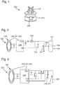
- Fig. 1 to 12 show an inventive laboratory automation system 10.
- the laboratory automation system 10 comprises an inventive laboratory sample distribution system 100.
- the laboratory sample distribution system 100 comprises an inventive laboratory system 200.
- the laboratory system 200 comprises a sample container carrier 210.
- the sample container carrier 210 is adapted to carry a laboratory sample container 130 and comprises a removal detector 220.
- the removal detector 220 is adapted to interact with the laboratory sample container 130 to detect a removal of the carried laboratory sample container 130 from the sample container carrier 210.
- the laboratory system 200 is adapted to determine based on the detected removal, that a before valid logic assignment of the sample container carrier 210 to the carried laboratory sample container 130 is invalid.
- the laboratory sample container 130 is designed as a tube and has an opening 131 at an, in particular upper, end, as shown in Fig. 2 and 8 to 12 . Furthermore, the laboratory sample container 130 contains a sample 139 in form of a liquid.
- the sample container carrier 210 comprises at least one holding element 219, as shown in Fig. 1 , 8 to 10 and 12 .
- the at least one holding element 219 is adapted to hold the laboratory sample container 130, in particular at a circumference of the laboratory sample container 130.
- the sample container carrier 130 comprises a holding region, in particular defined by the at least one holding element 219, for the laboratory sample container 130.
- the removal detector 220 is arranged in a bottom of the sample container carrier 210, in particular at an, in particular lower, end of the holding region.
- the removal detector 220 is adapted to interact with the laboratory sample container 130 by contact, in particular by contacting the laboratory sample container 130 at its circumference.
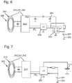
- the removal detector 220 comprises a switch 221, in particular a mechanical switch, as shown in Fig. 2 to 7 .
- the switch 221 is adapted to be depressed by the laboratory sample container 130, if present, and not depressed, if the laboratory sample container 130 is absent, in particular by a spring.
- the removal detector may be adapted to interact with the laboratory sample container contactless. Additionally or alternatively in alternative embodiments the removal detector may comprise an optical sensor, a capacitive sensor, a pressure sensor, a temperature sensor, and/or a shape memory alloy being adapted to interact with the laboratory sample container to detect a removal of the carried laboratory sample container from the sample container carrier.
- the sample container carrier 210 comprises a memory element 230.
- the memory element 230 is adapted to store information based on, that the logic assignment is valid, and information based on, that the logic assignment is invalid.
- the memory element may be adapted to store information based on the detected removal, in particular a time of or a time period since the detected removal.
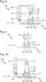
- the memory element 230 comprises a capacitor in Fig. 2 and 3 , a flip-flop in Fig. 4 and 6 , a microcontroller in Fig. 5 and 7 .
- the memory element has two states. A first state is, that the logic assignment is valid, and a second state is, that the logic assignment is invalid.
- the sample container carrier 210 comprises a transponder 240, in particular a RFID, NFC transponder, in particular comprising an antenna.
- the transponder 240 comprises a receiver 241 and a transmitter 242.
- the receiver 241 is adapted to receive information based on, that the logic assignment is valid and to store the information on the memory element 230. This may be denoted to arm the sample container carrier 210 or its memory element 230, respectively.
- the transmitter 242 is adapted to transmit information based on, that the logic assignment is valid. In alternative embodiments the transmitter may be adapted to transmit information based on the detected removal and/or information, that the logic assignment is invalid.
- the removal detector 220 is adapted to delete information based on, that the logic assignment is valid, in particular from the memory element 230, based on the detected removal.
- the removal detector 220 is adapted to store information based on, that the logic assignment is invalid, in particular on the memory element 230. If the valid information is deleted or the information is, that the logic assignment is invalid, respectively, the transmitter 242 does not transmit.
- the transponder 240 is adapted to receive an interrogation for the information, in particular by its receiver 241, and to transmit the information, in particular that the logic assignment is valid, in response to the received interrogation, in particular by its transmitter 242.
- the receiver 241 is adapted to collect energy, in particular from the received information and/or from the interrogation, and to supply the sample container carrier 210, in particular its memory element 230, with the collected energy.
- the sample container carrier 210 comprises an own power source 211, in particular a battery.
- the laboratory system 200 comprises a loading and assignment station 300, in particular comprising a gripper, as shown in Fig. 8 .
- the loading and assignment station 300 is adapted to load the laboratory sample container 130 on the sample container carrier 210 and to determine, that the logic assignment of the sample container carrier 210 to the loaded laboratory sample container 300 is valid.
- the laboratory system 200 comprises a barcode reader and assignment station 310, in particular comprising a camera.
- the barcode reader and assignment station 310 is adapted to read a barcode BC of the laboratory sample container 130 and to logically assign the read barcode BC to the sample container 210.
- the laboratory system comprises a transmitter station 320, in particular a RFID, NFC transmitter station, in particular comprising an antenna.
- the transmitter station 320 is adapted to transmit information, that the logic assignment is valid, to the sample container carrier 210. This may be denoted to arm the sample container carrier 210 or its memory element 230, respectively.
- the transmitter station 320 is adapted to transmit energy, in particular with the information, to the sample container carrier 210.
- the transmitter station 320 transmits the read barcode BC of the laboratory sample container 130 to the sample container 210. Thereby, information, that the logic assignment of the sample container carrier 210 to the loaded laboratory sample container 130 is valid, is transmitted to the sample container carrier 210.
- the loading and assignment station 300, the barcode reader and assignment station 310 and the transmitter station 320 are functionally coupled, in particular in signal connection with each other, as shown in Fig. 8 by a dotted line.
- sample container carrier 210 or its transponder 240 comprises a control circuit 243.
- the received barcode BC is stored by the control circuit 243.
- the memory element 230 comprising the capacitor in Fig. 2 is charged by power harvesting, in particular via an power harvesting output PW of the transponder 240 or its control circuit 243, respectively.
- the capacitor 230 is uncharged.
- the memory state can be read out by the transponder 240 or its control circuit 243, respectively, in particular via an digital input DI of the control circuit 243, with the next interrogation.
- the sample container carrier 210 comprises a time-delay-resistor 244, in particular in order to avoid a too fast recharge of the capacitor 230, in particular during the next interrogation. If the memory state is the second state, that the logic assignment is invalid, the stored barcode BC is deleted by the control circuit 243 and no response is transmitted. If the memory state is the first state, that the logic assignment is valid, the stored barcode BC is transmitted.
- the memory element 230 comprising the capacitor in Fig. 3 is charged by power harvesting, in particular triggered by an digital output DO of the control circuit 243.
- the capacitor 230 is uncharged.
- the memory state can be read out by the transponder 240 or its control circuit 243, respectively, with the next interrogation, wherein a recharge of the capacitor 230 can be avoided by not triggering the digital output DO.
- the memory element 230 comprising the flip-flop, in particular a RS flip-flop, in Fig. 4 is buffered by a capacitor 245 charged by power harvesting.
- the flip-flop 230 is set by the digital output DO.
- the flip-flop 230 is reset.
- the memory state can be read out by the transponder 240 or its control circuit 243, respectively, with the next interrogation, wherein a setting of the flip-flop 230 can be avoided by not triggering the digital output DO.
- the memory element 230 comprising the microcontroller in Fig. 5 is buffered by the capacitor 245 charged by power harvesting.
- the microcontroller 230 checks the removal detector 220 or a status of the removal detector 220, respectively, and stores it.
- the memory state can be read out by the transponder 240 or its control circuit 243, respectively, with the next interrogation, in particular by a bus connection in between the control circuit 243 and the microcontroller 230.
- the memory element 230 comprising the flip-flop, in particular a RS flip-flop, in Fig. 6 is buffered by the capacitor 245 charged by power harvesting.
- the flip-flop 230 is set by the digital output DO.
- a microcontroller 246 is supplied by power harvesting, in particular with the collected energy.
- the memory state can be read out by the transponder 240 or its control circuit 243, respectively, with the next interrogation, in particular by a bus connection in between the control circuit 243 and the flip-flop 230 via the microcontroller 246.
- the microcontroller 246 is adapted, in particular only adapted, for communication between the control circuit 243 and the flip-flop 230.
- the memory element 230 comprising the microcontroller in Fig. 7 is powered by the power source 211.
- the microcontroller 230 checks the removal detector 220 or a status of the removal detector 220, respectively, and stores it, in particular by a signal from a digital output to a digital input. When the laboratory sample container 130 is removed, the digital input detects this. The digital output may be set to low, what in particular may save energy.
- the memory state can be read out by the transponder 240 or its control circuit 243, respectively, with the next interrogation, in particular by a bus connection in between the control circuit 243 and the microcontroller 230.
- the sample container carrier 210 is adapted to determine based on the detected removal, that the before valid logic assignment of the sample container carrier 210 to the carried laboratory sample container 130 is invalid.
- the laboratory system 200 comprises a receiver station 330, in particular a RFID, NFC receiver station, in particular comprising an antenna, as shown in Fig. 10 .
- the receiver station 330 is adapted to receive information based on, that the logic assignment is valid, in particular the barcode BC of the laboratory sample container 130, from the sample container carrier 210.
- the receiver station may be adapted to receive information based on the detected removal and/or information, that the logic assignment is invalid.
- the receiver station 330 is adapted to transmit the interrogation and the sample container carrier 210 responds, if the logic assignment is still valid. If the valid information is deleted, the sample container carrier 210 does not respond and the receiver station 330 does not receive information. This enables the receiver station 330 to recognize, that the logic assignment is invalid.
- the receiver station 330 is adapted to transmit energy, in particular with the interrogation, to the sample container carrier 210.
- the laboratory automation system 10 comprises a number of analytical stations 20.
- the number of analytical stations 20 is adapted to analyze the sample 139.
- the laboratory automation system 200 is adapted to prevent analyzing, in particular by the number of analytical stations 20, and/or logically assigning an analytical result to the sample 139 contained by the carried laboratory sample container 130 based on the determined invalid logic assignment. In particular the sample container carrier 210 is rejected based on the determined invalid logic assignment.
- the laboratory automation system 10 is adapted to allow analyzing and/or logically assigning the analytical result to the sample 139 contained by the carried laboratory sample container 130 based on the valid logic assignment.
- receiver station 330 and the number of analytical stations 20 are functionally coupled, in particular in signal connection with each other, as shown in Fig. 10 by a dotted line.
- the logic assignment in particular the from the sample container carrier 210 transmitted and from the receiver station 330 received valid logic assignment in form of the barcode BC, allows or makes it possible to control and track the laboratory sample container 130 or the sample 139 contained by the laboratory sample container 139, respectively, over a workflow or a processing path, respectively.
- more than the two analytical stations 20 shown in Fig. 11 may be comprised in the laboratory automation system 10.
- the laboratory sample container 130 or its opening 131, respectively, is open for processing, in particular analyzing, the sample 139 contained by the laboratory sample container 130.
- sample container carrier 210 is adapted to move the carried, in particular open, laboratory sample container 130 in the laboratory sample distribution system 100, as shown in Fig. 8 to 11 , and/or in the laboratory automation system 10.
- the laboratory sample distribution system 100 comprises a transport plane 110, a number of drive elements 120 and a control device 125.
- the transport plane 110 is adapted to support the sample container carrier 210.
- the number of drive elements 120 is adapted to move the sample container carrier 210 on the transport plane 110.
- the control device 125 is configured to control the number of drive elements 120, such that the sample container carrier 210 moves on the transport plane 110 along a corresponding transport path.
- the laboratory automation system 10 comprises a number of pre-analytical stations and/or post-analytical stations.
- the loading and assignment station 300, the barcode reader and assignment station 310, the transmitter station 320, the receiver station 330, the number of analytical stations 20, the number of pre-analytical stations and the number of post-analytical stations are arranged adjacent to the laboratory sample distribution system 100, in particular to the transport plane 110.
- the laboratory sample distribution system 100 is adapted to move the sample container carrier 210 to the loading and assignment station 300, the barcode reader and assignment station 310, the transmitter station 320, the receiver station 330, the number of analytical stations 20, the number of pre-analytical stations and the number of post-analytical stations.
- control device 125 is configured to control the loading and assignment station 300, the barcode reader and assignment station 310, the transmitter station 320, the receiver station 330, the number of analytical stations 20, the number of pre-analytical stations and the number of post-analytical stations.
- sample container carrier 210 can be translationally moved in two dimensions x, y being perpendicular to each other on the transport plane 110.
- a sliding surface of the sample container carrier 210 is adapted to be in contact with the transport plane 110 and enables performing movements, in particular slides, of the sample container carrier 210 on the transport plane 110.
- the laboratory sample distribution system 100 comprises a plurality of sample container carriers 110. Self-evidently, more than the three sample container carriers 210 shown in Fig. 11 may be comprised in the laboratory sample distribution system 100.
- the control device 125 is configured to control the number of drive elements 120, such that the plurality of sample container carriers 210 moves on the transport plane 110 along corresponding, in particular individual, transport paths, simultaneously.
- the sample container carrier 210 comprises a magnetically active device 215, in particular in form of a permanent magnet, as shown in Fig. 12 .
- the number of drive elements 120 comprises a number of electro-magnetic actuators 121.
- the number of electro-magnetic actuators 121 is stationary arranged below the transport plane 110 and is adapted to move the sample container carrier 210 on the transport plane 110 by applying a magnetic drive force to the sample container carrier 210.
- the control device 125 is configured to control the number of electro-magnetic actuators 121, such that the sample container carrier 210 moves on the transport plane 110 along the corresponding transport path.
- the number of electro-magnetic actuators 121 is adapted to generate a magnetic field to move the sample container carrier 210 on the transport plane 110.
- the magnetically active device 215 is adapted to interact with the magnetic field generated by the number of electro-magnetic actuators 121, such that the magnetic drive force is applied to the sample container carrier 210.
- the number of electro-magnetic actuators 121 can be driven individually in order to generate the magnetic field.
- the number of electro-magnetic actuators 121 is implemented as solenoids having a solid ferromagnetic core.
- the electro-magnetic actuators 121 are quadratically arranged in a grid having rows and columns, in particular in a plane parallel to the transport plane 110. In each center of a quadrat formed by corresponding electro-magnetic actuators 121 no electro-magnetic actuator is arranged. In other words: in each second row in each second position there is no electro-magnetic actuator 121.
- the laboratory sample distribution system 100 comprises a number of Hall-sensors 140.
- the number of Hall-sensors 140 is arranged, such that a position of a respective sample container carrier 210 on the transport plane 110 can be detected.
- the control device 125 is functionally coupled to, in particular in signal connection with, the Hall-sensors 140 for detecting the position of the sample container carrier 210.
- the control device 125 is adapted to control the electro-magnetic actuators 121 in response to the detected position.
- the invention provides a laboratory system, which enables to ensure integrity of a logic assignment of an analytical result to a sample. Furthermore, the invention provides a laboratory sample distribution system comprising such a laboratory system and a laboratory automation system comprising such a laboratory system and/or such a laboratory sample distribution system.
Landscapes
- Physics & Mathematics (AREA)
- General Physics & Mathematics (AREA)
- Health & Medical Sciences (AREA)
- Chemical & Material Sciences (AREA)
- Immunology (AREA)
- Biochemistry (AREA)
- General Health & Medical Sciences (AREA)
- Analytical Chemistry (AREA)
- Life Sciences & Earth Sciences (AREA)
- Pathology (AREA)
- Engineering & Computer Science (AREA)
- Quality & Reliability (AREA)
- Condensed Matter Physics & Semiconductors (AREA)
- Clinical Laboratory Science (AREA)
- Chemical Kinetics & Catalysis (AREA)
- Automatic Analysis And Handling Materials Therefor (AREA)
- Non-Mechanical Conveyors (AREA)
Abstract
Description
- The invention relates to a laboratory system, a laboratory sample distribution system comprising such a laboratory system and a laboratory automation system comprising such a laboratory system and/or such a laboratory sample distribution system.
- Known laboratory automation systems typically comprise a number of analytical stations and a laboratory sample distribution in order to move samples contained by laboratory sample containers carried by sample container carriers to the number of analytical stations. Such a laboratory automation system is shown in document
WO 2013/064662 A1 . The laboratory automation system comprises a memory device being adapt to store matching pairs of a unique identification (ID) corresponding to a sample container carrier and a laboratory sample container ID being carried by the sample container carrier, making it possible to control and track laboratory sample containers over a processing path. - It is the object of the invention to provide a laboratory system, which enables to ensure integrity of a logic assignment of an analytical result to a sample. It is a further object of the invention to provide a laboratory sample distribution system comprising such a laboratory system and a laboratory automation system comprising such a laboratory system and/or such a laboratory sample distribution system.
- These objects are solved by a laboratory system according to
claim 1, a laboratory sample distribution system according to claim 13 and a laboratory automation system according to claim 15. Preferred embodiments are defined in the dependent claims. - The invention relates to a laboratory system for a laboratory automation system. The laboratory system comprises a sample container carrier. The sample container carrier is adapted to carry a laboratory sample container and comprises a removal detector. The removal detector is adapted to interact with the laboratory sample container to detect, in particular to automatically detect, a removal or an unloading, respectively, of the carried laboratory sample container from the sample container carrier. Furthermore, the laboratory system is adapted to determine, in particular to automatically determine, based on or in dependence of, respectively, the detected removal, that a before valid logic assignment of the sample container carrier to the carried laboratory sample container is invalid.
- In particular the before by the sample container carrier carried laboratory sample container may be unintentionally interchanged, in particular by failure or manipulation, with another laboratory sample container, for which the logic assignment may be invalid. Thereby, a logic assignment of an analytical result of another sample contained by the carried another laboratory sample container to a sample contained by the before carried laboratory sample container indirectly by use of the logic assignment of the sample container carrier to the before carried laboratory sample container may be wrong. So far it was possible, that this wrong logic assignment may have remained undetected.
- Now the removal detector of the sample container carrier enables to detect a possible interchange by detecting the removal. Since the laboratory sample container may be interchanged, it is determined based on the detected removal, that the before valid logic assignment of the sample container carrier to the carried laboratory sample container is invalid. Thereby, a risk of a wrong logic assignment of an analytical result to a sample is reduced or even eliminated. In other words: the laboratory system enables to ensure integrity of a logic assignment of an analytical result to a sample and thereby to a corresponding patient.
- In detail the laboratory sample container may be designed as a tube and/or may have an opening at an upper, top and/or face end. Furthermore, the laboratory sample container may be made of glass or transparent plastic or any other, in particular somewhat, solid material. Moreover, the laboratory sample container or its opening, respectively, may be closed by a closure or a cap. The closure may comprise rubber and/or plastic or may completely consist of rubber and/or plastic. Further, the closure may be embodied as a foil, in particular a flexible foil, or film or tape or as a lid, in particular as a rigid lid.
- Furthermore, the laboratory sample container may be adapted to contain a sample. The sample may be a blood sample, a serum sample, a plasma sample, a urine sample, a CFS sample, a body sample, a water sample or a chemical sample. In particular the sample may be a liquid. The laboratory sample container or its opening, respectively, may be open for processing, in particular analyzing, the sample, if present, contained by the laboratory sample container.
- Moreover, the laboratory sample container may comprise a, in particular unique, ID. The ID may be representative for the sample, if present, contained by the laboratory sample container. In particular the ID may comprise or be a barcode. The ID of the laboratory sample container may be denoted as container ID.
- However, it may be too complicated, in particular too time-consuming, or even impossible to directly use the laboratory sample container, in particular its container ID, if present, for identification of the sample in the laboratory automation system all the time and/or in each situation, in particular in a workflow of the laboratory automation system.
- Instead of container identification the sample container carrier, in particular an ID of the sample container carrier, may be directly used for identification of the sample, if present, contained by the carried laboratory sample container in the laboratory automation system.
- In particular the sample container carrier may be adapted to comprise a, in particular unique, ID. The ID may be representative for the sample container carrier and/or the carried laboratory sample container and/or the sample, if present, contained by the carried laboratory sample container. The ID of the sample container carrier may be denoted as carrier ID.
- The logic assignment may be an assignment of the carrier ID to the container ID. Further, the assignment may be denoted as link or association. Valid may be denoted as correct. Invalid may be denoted as incorrect.
- Furthermore, the sample container carrier does not have to comprise any means for identification of the, in particular carried, laboratory sample container and/or the sample, if present, contained by the laboratory sample container. In particular the sample container carrier does not have to comprise a reader for reading the container ID.
- Moreover, the sample container carrier may be adapted or embodied to carry only one or a single laboratory sample container. The sample container carrier may be denoted as single sample container carrier. Further, the sample container carrier may be adapted to move the carried, in particular open, laboratory sample container in a laboratory sample distribution system and/or in the laboratory automation system.
- In particular the sample container carrier may be adapted to determine based on the detected removal, that the before valid logic assignment of the sample container carrier to the carried laboratory sample container is invalid.
- The removal detector may be adapted to interact with the laboratory sample container contactless or by contact, in particular by contacting the laboratory sample container at an outside, in particular at a circumference, of the laboratory sample container. In particular the removal detector may be adapted to detect a presence of the laboratory sample container. The removal detector may be denoted as presence detector. Furthermore, the removal detector may be arranged in a bottom or a laboratory sample container adapter of the sample container carrier.
- According to an embodiment of the invention the removal detector comprises a switch, in particular a microswitch, an optical sensor, a capacitive sensor, a pressure sensor, a temperature sensor, and/or a shape memory alloy being adapted to interact with the laboratory sample container to detect, in particular to automatically detect, a removal of the carried laboratory sample container from the sample container carrier. In particular the switch may be a mechanical switch, which may be depressed by the laboratory sample container, if present, and not depressed, if the laboratory sample container is absent, in particular by a spring.
- According to an embodiment of the invention the sample container carrier comprises a memory element. The memory element is adapted to store, in particular to automatically store, information based on the detected removal, information based on, that the logic assignment is valid, and/or information based on, that the logic assignment is invalid. This may enable or allow, that information does not have to be transmitted on or at detection or determination, but may be transmitted at a later time. In particular the memory element may be a re-writable and/or non-volatile memory element. The memory element may be an electric memory element. In particular the memory element may comprise a capacitor, a flip-flop or a latch, respectively, a microcontroller and/or a semiconductor memory. The memory element may be have two, in particular stable, states and may be used to store state information. In particular a first state may be, that the logic assignment is valid, and a from the first different, second state may be, that the logic assignment is invalid. Information based on the detected removal may be a time of or a time period since the detected removal. The time or the time period may be compared with a time or a time period since the last, in particular intentional, removal of a laboratory sample container from the sample container carrier or since a, in particular intentional, loading of the laboratory sample container on the sample container carrier, in particular by the laboratory system or a control device of the laboratory system, respectively. Based on the comparison the laboratory system or its control device, if present, may determine, that the before valid logic assignment of the sample container carrier to the carried laboratory sample container is invalid. The control device may comprise or be an integrated circuit, a tablet computer, a smartphone or a computer. Information based on, that the logic assignment is valid, may be information about the laboratory sample container, in particular the container ID, if present, and/or the sample, if present, contained by the laboratory sample container. Based on the detected removal, the valid information may be deleted or changed, in particular such that the invalid information may be generated.
- According to an embodiment of the invention the sample container carrier comprises a receiver. The receiver is adapted to receive, in particular to automatically and/or wireless receive, information based on, that the logic assignment is valid, in particular from outside the sample container carrier, and to store the information on the memory element. In particular this may be denoted to arm the sample container carrier or its memory element, respectively. The receiver may be different from the removal detector. Additionally or alternatively the receiver may be an electric receiver and/or a wireless receiver, in particular a radio receiver, in particular comprising an antenna.
- According to an embodiment of the invention the sample container carrier comprises a transmitter. The transmitter is adapted to transmit, in particular to automatically and/or wireless transmit, information based on the detected removal, information based on, that the logic assignment is valid, and/or information, that the logic assignment is invalid, in particular to outside the sample container carrier. In particular the transmitter may be different from the removal detector. Additionally or alternatively the transmitter may be an electric transmitter and/or a wireless transmitter, in particular a radio transmitter, in particular comprising an antenna. Information may be such as described above in the context of the memory element. In particular if the valid information is deleted, the transmitter may be adapted not to transmit.
- According to an embodiment of the invention the sample container carrier comprises a transponder. The transponder comprises the transmitter and a receiver. Furthermore, the transponder is adapted to receive, in particular to automatically and/or wireless receive, an interrogation, in particular an interrogation signal or an interrogation wave, respectively, for the information, in particular by its receiver, and to transmit, in particular to automatically transmit, the information in response to the received interrogation, in particular by its transmitter. This may enable, that only the interrogated sample container carrier transmits. In particular the transponder may be different from the removal detector. Additionally or alternatively the transponder may be an electric transponder and/or a wireless transponder, in particular a radio transponder. The transmitter and the receiver may be combined, in particular they may be denoted as transceiver. The receiver may be embodied as described above. In particular the transponder may be embodied as a radio-frequency identification (RFID) label or tag.
- According to an embodiment of the invention the transponder is a near-field communication (NFC) transponder. This enables, that only the sample container carrier may be interrogated. In particular a communication range may be in the range from 1 centimeter (cm) to 10 cm, in particular from 2 cm to 8 cm, in particular from 3 cm to 6 cm, in particular 4 cm.
- According to an embodiment of the invention the receiver is adapted to collect, in particular to automatically collect, energy, in particular electrical energy and/or of the interrogation, and to supply, in particular to automatically supply, the sample container carrier, in particular its removal detector and/or its memory element, if present, with the collected energy. In particular the sample container carrier may be denoted as passive sample container carrier and/or power harvesting sample container carrier. In other words: the sample container carrier may be adapted to be only supplied by the collected energy. Further, in other words: the sample container carrier does not have to comprise an own power source, in particular an accumulator and/or a battery.
- According to an embodiment of the invention the laboratory system comprises a receiver station. The receiver station is adapted to receive, in particular to automatically and/or wireless receive, information based on the detected removal, information based on, that the logic assignment is valid, and/or information, that the logic assignment is invalid, from the sample container carrier. In particular the receiver station may be different from the sample container carrier. Additionally or alternatively the receiver station may be an electric receiver station and/or a wireless receiver station, in particular a radio receiver station, in particular comprising an antenna, in particular a RDIF receiver station and/or a NFC receiver station. In particular the receiver station may be adapted to transmit, in particular to automatically and/or wireless transmit, the interrogation. The receiver station may be denoted as reader station. Information may be such as described above in the context of the memory element. In particular if the valid information is deleted, the receiver station may not receive or not be able to read-out information. This enables or allows the receiver station to recognize, that the logic assignment is invalid.
- According to an embodiment of the invention the laboratory system comprises a transmitter station. The transmitter station is adapted to transmit, in particular to automatically and/or wireless transmit, information, that the logic assignment is valid, to the sample container carrier. In particular this may be denoted to arm the sample container carrier or its memory element, if present, respectively. Additionally or alternatively the transmitter station may be different from the sample container carrier. Furthermore, the transmitter station may be an electric transmitter station and/or a wireless transmitter station, in particular a radio transmitter station, in particular comprising an antenna, in particular a RDIF transmitter station and/or a NFC transmitter station. The transmitter station may be denoted as writer station. Information may be such as described above in the context of the memory element.
- According to an embodiment of the invention the laboratory system comprises a barcode reader and assignment station. The barcode reader and assignment station is adapted to read, in particular to automatically read, a barcode of the laboratory sample container and to logically assign, in particular to automatically assign, the read barcode to the sample container. In particular the barcode reader and assignment station may be adapted to transmit the read barcode to the sample container carrier. Additionally or alternatively the barcode reader and assignment station may be different from the sample container carrier. Furthermore, the barcode reader and assignment station may be an electric barcode reader and assignment station, in particular the barcode reader and assignment station may comprise a camera.
- According to an embodiment of the invention the laboratory system comprises a loading and assignment station. The loading and assignment station is adapted to load, in particular automatically load, the laboratory sample container on the sample container carrier and to determine, in particular to automatically determine, that the logic assignment of the sample container carrier to the loaded laboratory sample container is valid. In particular the loading and assignment station may be adapted to transmit information, that the logic assignment of the sample container carrier to the loaded laboratory sample container is valid, to the sample container carrier. Additionally or alternatively the loading and assignment station may be different from the sample container carrier. Furthermore, the loading and assignment station may be an electric loading and assignment station. Moreover, the loading and assignment station may be denoted as inserting and assignment station.
- The invention further relates to a laboratory sample distribution system for a laboratory automation system. The laboratory sample distribution system comprises a laboratory system as described above and a transport plane, a number of drive elements (e.g. 1 to 10000) and a, in particular the, control device. The transport plane is adapted to support the sample container carrier, in particular with the carried laboratory sample container. The number of drive elements is adapted to move, in particular to automatically move, the sample container carrier, in particular with the carried laboratory sample container, on the transport plane. The control device is configured to control, in particular to automatically control, the number of drive elements, such that the sample container carrier moves on the transport plane along a corresponding, in particular individual, transport path.
- By means of the laboratory system according to the invention, the advantages of the laboratory system according to the invention, as discussed above, may be made applicable for the laboratory sample distribution system.
- In particular the transport plane may be denoted as transport surface. To support the sample container carrier be denoted to carry the sample container carrier. The sample container carrier may be translationally moved on or over the transport plane. Furthermore, the sample container carrier may be adapted to move in two dimensions on the transport plane. Moreover, the sample container carrier may slide over the transport plane. In particular the laboratory sample distribution system may comprise a plurality of sample container carriers (e.g. 1 to 1000), in particular as described above. The number of drive elements may be a number of electric drive elements. The control device may be configured to control the number of drive elements, such that the plurality of sample container carriers moves on the transport plane along corresponding, in particular individual, transport paths simultaneously. Further, the control device may comprise or be an integrated circuit, a tablet computer, a smartphone or a computer.
- Furthermore, the receiver station, the transmitter station, the barcode reader and assignment station and/or the loading and assignment station, if present, may be arranged adjacent or directly next to the laboratory sample distribution system, in particular to the transport plane of the laboratory sample distribution system.
- According to an embodiment of the invention the sample container carrier comprises a magnetically active device. The number of drive elements comprises a number of electro-magnetic actuators. The number of electro-magnetic actuators is stationary arranged below the transport plane and is adapted to move, in particular to automatically move, the sample container carrier on the transport plane by applying a magnetic drive force to the sample container carrier. The control device is configured to control, in particular to automatically control, the number of electro-magnetic actuators, such that the sample container carrier moves on the transport plane along the corresponding transport path.
- In particular the number of electro-magnetic actuators may be adapted to generate a magnetic field to move the sample container carrier on the transport plane. The magnetically active device may be adapted to interact with the magnetic field generated by the number of electro-magnetic actuators, such that the magnetic drive force is applied to the sample container carrier. In particular the magnetically active device may be a permanent magnet or an electromagnet. Additionally or alternatively the magnetically active device may comprise a magnetically soft material. The number of electro-magnetic actuators may be a number of solenoids surrounding ferromagnetic cores. Furthermore, the number of electro-magnetic actuators may be driven or energized individually in order to generate or to provide the magnetic field. Moreover, the electro-magnetic actuators may be arranged in two dimensions, in particular in a grid having rows and columns, along which the electro-magnetic actuators are arranged. Further, the electro-magnetic actuators may be arranged in a plane parallel to the transport plane.
- Additionally or alternatively the number of drive elements may comprise at least one wheel and a drive motor to drive the wheel. The drive motor and the wheel may be adapted to move, in particular to automatically move, the sample container carrier on the transport plane. The control device may be configured to control, in particular to automatically control, the at least one wheel and/or the drive motor, such that the sample container carrier moves on the transport plane along the corresponding transport path. In particular the sample container carrier may comprise the at least one wheel and/or the at least one drive motor.
- The invention further relates to a laboratory automation system. The laboratory automation system comprises a number of analytical stations. The number of analytical stations is adapted to analyze, in particular to automatically analyze, a sample. Furthermore, the laboratory automation system comprises a laboratory system as described above and/or a laboratory sample distribution system as described above. The laboratory sample distribution system, if present, is adapted to move, in particular to automatically move, the sample container carrier to the number of analytical stations. The laboratory automation system or its control device, if present, is adapted to prevent, in particular to automatically prevent, analyzing and/or logically assigning an analytical result to the sample contained by the carried laboratory sample container based on the determined invalid logic assignment, in particular of the sample container carrier to the laboratory sample container.
- By means of the laboratory system and/or the laboratory sample distribution system according to the invention, the advantages of the laboratory system and/or the laboratory sample distribution system according to the invention, as discussed above, may be made applicable for the laboratory automation system.
- In other words: the laboratory automation system or its control device, if present, may be adapted to reject, in particular to automatically reject, the sample container carrier, the carried laboratory sample container and/or the sample contained by the laboratory sample container based on the determined invalid logic assignment. Additionally or alternatively, the laboratory automation system or its control device, if present, may be adapted to allow, in particular to automatically allow, analyzing and/or logically assigning the analytical result to the sample contained by the carried laboratory sample container based on the, in particular determined, valid logic assignment, in particular of the sample container carrier to the laboratory sample container.
- The number of analytical stations may be different from the sample container carrier. In particular the number of analytical stations may be adapted to use the sample or a part of the sample and a reagent to generate a measuring signal, the measuring signal indicating if and in which concentration, if any, an analyte is existing.
- Furthermore, the laboratory automation system may comprise a number of pre-analytical stations and/or post-analytical stations. The number of pre-analytical stations may be adapted to perform any kind of pre-processing of the sample, the laboratory sample container and/or the sample container carrier. The number of post-analytical stations may be adapted to perform any kind of post-processing of the sample, the laboratory sample container and/or the sample container carrier.
- The number of pre-analytical, analytical and/or post-analytical stations may comprise at least one of a decapping station, a recapping station, an aliquot station, a centrifugation station, an archiving station, a pipetting station, a sorting station, a tube type identification station, a sample quality determining station, an add-on buffer station, a liquid level detection station, a sealing/desealing station, a pushing station, a belt station, a conveying system station and/or a gripper station for moving the laboratory sample container to or from the sample container carrier.
- Moreover, the number of analytical, pre-analytical and/or post-analytical stations, if present, may be arranged adjacent or directly next to the laboratory sample distribution system, if present, in particular to the transport plane of the laboratory sample distribution system.
- In particular the laboratory sample distribution system, if present, may be adapted to move the sample container carrier to the number of pre-analytical stations, post-analytical stations, the receiver station, the transmitter station, the barcode reader and assignment station and/or the loading and assignment station, if present. In particular the laboratory sample distribution system may be adapted to move the sample container carrier in between the stations.
- In the following, an embodiment of the invention will be described in detail with reference to the drawings. Throughout the drawings, the same elements will be denoted by the same reference numerals.
- Fig. 1
- shows a perspective view of a sample container carrier of a laboratory system according to the invention of a laboratory sample distribution system according to the invention of a laboratory automation system according to the invention,
- Fig. 2
- shows a schematic diagram of the sample container carrier of
Fig. 1 comprising a memory element in form of a capacitor, - Fig. 3
- shows another schematic diagram of the sample container carrier of
Fig. 1 comprising a memory element in form of a capacitor, - Fig. 4
- shows another schematic diagram of the sample container carrier of
Fig. 1 comprising a memory element in form of a flip-flop, - Fig. 5
- shows another schematic diagram of the sample container carrier of
Fig. 1 comprising a memory element in form of a microcontroller, - Fig. 6
- shows another schematic diagram of the sample container carrier of
Fig. 1 comprising a memory element in form of a flip-flop, - Fig. 7
- shows another schematic diagram of the sample container carrier of
Fig. 1 comprising a memory element in form of a microcontroller, - Fig. 8
- shows a side view of a loading and assignment station, a barcode reader and assignment station and a transmitter station of the laboratory system according to the invention,
- Fig. 9
- shows a removal of a laboratory sample container from the sample container carrier of
Fig. 1 , - Fig. 10
- shows a side view of a receiver station of the laboratory system according to the invention and an analytical station of the laboratory automation system according to the invention,
- Fig. 11
- shows a perspective view of the laboratory sample distribution system according to the invention, and
- Fig. 12
- shows a side view of the sample container carrier of
Fig. 1 . -
Fig. 1 to 12 show an inventivelaboratory automation system 10. Thelaboratory automation system 10 comprises an inventive laboratorysample distribution system 100. The laboratorysample distribution system 100 comprises aninventive laboratory system 200. - The
laboratory system 200 comprises asample container carrier 210. Thesample container carrier 210 is adapted to carry alaboratory sample container 130 and comprises aremoval detector 220. Theremoval detector 220 is adapted to interact with thelaboratory sample container 130 to detect a removal of the carriedlaboratory sample container 130 from thesample container carrier 210. Furthermore, thelaboratory system 200 is adapted to determine based on the detected removal, that a before valid logic assignment of thesample container carrier 210 to the carriedlaboratory sample container 130 is invalid. - In the shown embodiment the
laboratory sample container 130 is designed as a tube and has anopening 131 at an, in particular upper, end, as shown inFig. 2 and8 to 12 . Furthermore, thelaboratory sample container 130 contains asample 139 in form of a liquid. - In detail the
sample container carrier 210 comprises at least one holdingelement 219, as shown inFig. 1 ,8 to 10 and12 . The at least one holdingelement 219 is adapted to hold thelaboratory sample container 130, in particular at a circumference of thelaboratory sample container 130. Moreover, thesample container carrier 130 comprises a holding region, in particular defined by the at least one holdingelement 219, for thelaboratory sample container 130. - The
removal detector 220 is arranged in a bottom of thesample container carrier 210, in particular at an, in particular lower, end of the holding region. - In the shown embodiment the
removal detector 220 is adapted to interact with thelaboratory sample container 130 by contact, in particular by contacting thelaboratory sample container 130 at its circumference. In detail theremoval detector 220 comprises aswitch 221, in particular a mechanical switch, as shown inFig. 2 to 7 . Theswitch 221 is adapted to be depressed by thelaboratory sample container 130, if present, and not depressed, if thelaboratory sample container 130 is absent, in particular by a spring. - In alternative embodiments the removal detector may be adapted to interact with the laboratory sample container contactless. Additionally or alternatively in alternative embodiments the removal detector may comprise an optical sensor, a capacitive sensor, a pressure sensor, a temperature sensor, and/or a shape memory alloy being adapted to interact with the laboratory sample container to detect a removal of the carried laboratory sample container from the sample container carrier.
- Further, the
sample container carrier 210 comprises amemory element 230. In the shown embodiment thememory element 230 is adapted to store information based on, that the logic assignment is valid, and information based on, that the logic assignment is invalid. In alternative embodiments the memory element may be adapted to store information based on the detected removal, in particular a time of or a time period since the detected removal. - In detail the
memory element 230 comprises a capacitor inFig. 2 and 3 , a flip-flop inFig. 4 and6 , a microcontroller inFig. 5 and7 . In particular the memory element has two states. A first state is, that the logic assignment is valid, and a second state is, that the logic assignment is invalid. - Furthermore, the
sample container carrier 210 comprises atransponder 240, in particular a RFID, NFC transponder, in particular comprising an antenna. Thetransponder 240 comprises a receiver 241 and a transmitter 242. - The receiver 241 is adapted to receive information based on, that the logic assignment is valid and to store the information on the
memory element 230. This may be denoted to arm thesample container carrier 210 or itsmemory element 230, respectively. - In the shown embodiment the transmitter 242 is adapted to transmit information based on, that the logic assignment is valid. In alternative embodiments the transmitter may be adapted to transmit information based on the detected removal and/or information, that the logic assignment is invalid.
- In detail the
removal detector 220 is adapted to delete information based on, that the logic assignment is valid, in particular from thememory element 230, based on the detected removal. In other words: theremoval detector 220 is adapted to store information based on, that the logic assignment is invalid, in particular on thememory element 230. If the valid information is deleted or the information is, that the logic assignment is invalid, respectively, the transmitter 242 does not transmit. - In particular the
transponder 240 is adapted to receive an interrogation for the information, in particular by its receiver 241, and to transmit the information, in particular that the logic assignment is valid, in response to the received interrogation, in particular by its transmitter 242. - Moreover, in
Fig. 2 to 6 the receiver 241 is adapted to collect energy, in particular from the received information and/or from the interrogation, and to supply thesample container carrier 210, in particular itsmemory element 230, with the collected energy. - In
Fig. 7 thesample container carrier 210 comprises anown power source 211, in particular a battery. - Further, the
laboratory system 200 comprises a loading andassignment station 300, in particular comprising a gripper, as shown inFig. 8 . The loading andassignment station 300 is adapted to load thelaboratory sample container 130 on thesample container carrier 210 and to determine, that the logic assignment of thesample container carrier 210 to the loadedlaboratory sample container 300 is valid. - Furthermore, the
laboratory system 200 comprises a barcode reader andassignment station 310, in particular comprising a camera. The barcode reader andassignment station 310 is adapted to read a barcode BC of thelaboratory sample container 130 and to logically assign the read barcode BC to thesample container 210. - Moreover, the laboratory system comprises a
transmitter station 320, in particular a RFID, NFC transmitter station, in particular comprising an antenna. Thetransmitter station 320 is adapted to transmit information, that the logic assignment is valid, to thesample container carrier 210. This may be denoted to arm thesample container carrier 210 or itsmemory element 230, respectively. In particular thetransmitter station 320 is adapted to transmit energy, in particular with the information, to thesample container carrier 210. - In the shown embodiment the
transmitter station 320 transmits the read barcode BC of thelaboratory sample container 130 to thesample container 210. Thereby, information, that the logic assignment of thesample container carrier 210 to the loadedlaboratory sample container 130 is valid, is transmitted to thesample container carrier 210. In particular the loading andassignment station 300, the barcode reader andassignment station 310 and thetransmitter station 320 are functionally coupled, in particular in signal connection with each other, as shown inFig. 8 by a dotted line. - In detail the
sample container carrier 210 or itstransponder 240, respectively, comprises acontrol circuit 243. The received barcode BC is stored by thecontrol circuit 243. - Further, the
memory element 230 comprising the capacitor inFig. 2 is charged by power harvesting, in particular via an power harvesting output PW of thetransponder 240 or itscontrol circuit 243, respectively. When thelaboratory sample container 130 is removed, as shown inFig. 9 , thecapacitor 230 is uncharged. The memory state can be read out by thetransponder 240 or itscontrol circuit 243, respectively, in particular via an digital input DI of thecontrol circuit 243, with the next interrogation. Furthermore, thesample container carrier 210 comprises a time-delay-resistor 244, in particular in order to avoid a too fast recharge of thecapacitor 230, in particular during the next interrogation. If the memory state is the second state, that the logic assignment is invalid, the stored barcode BC is deleted by thecontrol circuit 243 and no response is transmitted. If the memory state is the first state, that the logic assignment is valid, the stored barcode BC is transmitted. - The
memory element 230 comprising the capacitor inFig. 3 is charged by power harvesting, in particular triggered by an digital output DO of thecontrol circuit 243. When thelaboratory sample container 130 is removed, thecapacitor 230 is uncharged. The memory state can be read out by thetransponder 240 or itscontrol circuit 243, respectively, with the next interrogation, wherein a recharge of thecapacitor 230 can be avoided by not triggering the digital output DO. - The
memory element 230 comprising the flip-flop, in particular a RS flip-flop, inFig. 4 is buffered by acapacitor 245 charged by power harvesting. The flip-flop 230 is set by the digital output DO. When thelaboratory sample container 130 is removed, the flip-flop 230 is reset. The memory state can be read out by thetransponder 240 or itscontrol circuit 243, respectively, with the next interrogation, wherein a setting of the flip-flop 230 can be avoided by not triggering the digital output DO. - The
memory element 230 comprising the microcontroller inFig. 5 is buffered by thecapacitor 245 charged by power harvesting. Themicrocontroller 230 checks theremoval detector 220 or a status of theremoval detector 220, respectively, and stores it. The memory state can be read out by thetransponder 240 or itscontrol circuit 243, respectively, with the next interrogation, in particular by a bus connection in between thecontrol circuit 243 and themicrocontroller 230. - The
memory element 230 comprising the flip-flop, in particular a RS flip-flop, inFig. 6 is buffered by thecapacitor 245 charged by power harvesting. The flip-flop 230 is set by the digital output DO. When thelaboratory sample container 130 is removed, the flip-flop 230 is reset. Amicrocontroller 246 is supplied by power harvesting, in particular with the collected energy. The memory state can be read out by thetransponder 240 or itscontrol circuit 243, respectively, with the next interrogation, in particular by a bus connection in between thecontrol circuit 243 and the flip-flop 230 via themicrocontroller 246. In other words: themicrocontroller 246 is adapted, in particular only adapted, for communication between thecontrol circuit 243 and the flip-flop 230. - The
memory element 230 comprising the microcontroller inFig. 7 is powered by thepower source 211. Themicrocontroller 230 checks theremoval detector 220 or a status of theremoval detector 220, respectively, and stores it, in particular by a signal from a digital output to a digital input. When thelaboratory sample container 130 is removed, the digital input detects this. The digital output may be set to low, what in particular may save energy. The memory state can be read out by thetransponder 240 or itscontrol circuit 243, respectively, with the next interrogation, in particular by a bus connection in between thecontrol circuit 243 and themicrocontroller 230. - In other words: the
sample container carrier 210 is adapted to determine based on the detected removal, that the before valid logic assignment of thesample container carrier 210 to the carriedlaboratory sample container 130 is invalid. - Further, the
laboratory system 200 comprises areceiver station 330, in particular a RFID, NFC receiver station, in particular comprising an antenna, as shown inFig. 10 . In the shown embodiment thereceiver station 330 is adapted to receive information based on, that the logic assignment is valid, in particular the barcode BC of thelaboratory sample container 130, from thesample container carrier 210. In alternative embodiments the receiver station may be adapted to receive information based on the detected removal and/or information, that the logic assignment is invalid. - In detail the
receiver station 330 is adapted to transmit the interrogation and thesample container carrier 210 responds, if the logic assignment is still valid. If the valid information is deleted, thesample container carrier 210 does not respond and thereceiver station 330 does not receive information. This enables thereceiver station 330 to recognize, that the logic assignment is invalid. In particular thereceiver station 330 is adapted to transmit energy, in particular with the interrogation, to thesample container carrier 210. - Furthermore, the
laboratory automation system 10 comprises a number ofanalytical stations 20. The number ofanalytical stations 20 is adapted to analyze thesample 139. Thelaboratory automation system 200 is adapted to prevent analyzing, in particular by the number ofanalytical stations 20, and/or logically assigning an analytical result to thesample 139 contained by the carriedlaboratory sample container 130 based on the determined invalid logic assignment. In particular thesample container carrier 210 is rejected based on the determined invalid logic assignment. - Additionally, the
laboratory automation system 10 is adapted to allow analyzing and/or logically assigning the analytical result to thesample 139 contained by the carriedlaboratory sample container 130 based on the valid logic assignment. - In particular the
receiver station 330 and the number ofanalytical stations 20 are functionally coupled, in particular in signal connection with each other, as shown inFig. 10 by a dotted line. - The logic assignment, in particular the from the
sample container carrier 210 transmitted and from thereceiver station 330 received valid logic assignment in form of the barcode BC, allows or makes it possible to control and track thelaboratory sample container 130 or thesample 139 contained by thelaboratory sample container 139, respectively, over a workflow or a processing path, respectively. - Self-evidently, more than the two
analytical stations 20 shown inFig. 11 may be comprised in thelaboratory automation system 10. - The
laboratory sample container 130 or itsopening 131, respectively, is open for processing, in particular analyzing, thesample 139 contained by thelaboratory sample container 130. - Moreover, the
sample container carrier 210 is adapted to move the carried, in particular open,laboratory sample container 130 in the laboratorysample distribution system 100, as shown inFig. 8 to 11 , and/or in thelaboratory automation system 10. - The laboratory
sample distribution system 100 comprises atransport plane 110, a number ofdrive elements 120 and acontrol device 125. Thetransport plane 110 is adapted to support thesample container carrier 210. The number ofdrive elements 120 is adapted to move thesample container carrier 210 on thetransport plane 110. Thecontrol device 125 is configured to control the number ofdrive elements 120, such that thesample container carrier 210 moves on thetransport plane 110 along a corresponding transport path. - Further, the
laboratory automation system 10 comprises a number of pre-analytical stations and/or post-analytical stations. - The loading and
assignment station 300, the barcode reader andassignment station 310, thetransmitter station 320, thereceiver station 330, the number ofanalytical stations 20, the number of pre-analytical stations and the number of post-analytical stations are arranged adjacent to the laboratorysample distribution system 100, in particular to thetransport plane 110. - Furthermore, the laboratory
sample distribution system 100 is adapted to move thesample container carrier 210 to the loading andassignment station 300, the barcode reader andassignment station 310, thetransmitter station 320, thereceiver station 330, the number ofanalytical stations 20, the number of pre-analytical stations and the number of post-analytical stations. - Moreover, the
control device 125 is configured to control the loading andassignment station 300, the barcode reader andassignment station 310, thetransmitter station 320, thereceiver station 330, the number ofanalytical stations 20, the number of pre-analytical stations and the number of post-analytical stations. - In detail the
sample container carrier 210 can be translationally moved in two dimensions x, y being perpendicular to each other on thetransport plane 110. In the shown embodiment a sliding surface of thesample container carrier 210 is adapted to be in contact with thetransport plane 110 and enables performing movements, in particular slides, of thesample container carrier 210 on thetransport plane 110. In particular the laboratorysample distribution system 100 comprises a plurality ofsample container carriers 110. Self-evidently, more than the threesample container carriers 210 shown inFig. 11 may be comprised in the laboratorysample distribution system 100. Thecontrol device 125 is configured to control the number ofdrive elements 120, such that the plurality ofsample container carriers 210 moves on thetransport plane 110 along corresponding, in particular individual, transport paths, simultaneously. - In the shown embodiment the
sample container carrier 210 comprises a magneticallyactive device 215, in particular in form of a permanent magnet, as shown inFig. 12 . The number ofdrive elements 120 comprises a number of electro-magnetic actuators 121. The number of electro-magnetic actuators 121 is stationary arranged below thetransport plane 110 and is adapted to move thesample container carrier 210 on thetransport plane 110 by applying a magnetic drive force to thesample container carrier 210. Thecontrol device 125 is configured to control the number of electro-magnetic actuators 121, such that thesample container carrier 210 moves on thetransport plane 110 along the corresponding transport path. - In detail the number of electro-
magnetic actuators 121 is adapted to generate a magnetic field to move thesample container carrier 210 on thetransport plane 110. The magneticallyactive device 215 is adapted to interact with the magnetic field generated by the number of electro-magnetic actuators 121, such that the magnetic drive force is applied to thesample container carrier 210. Furthermore, the number of electro-magnetic actuators 121 can be driven individually in order to generate the magnetic field. In particular the number of electro-magnetic actuators 121 is implemented as solenoids having a solid ferromagnetic core. Moreover, the electro-magnetic actuators 121 are quadratically arranged in a grid having rows and columns, in particular in a plane parallel to thetransport plane 110. In each center of a quadrat formed by corresponding electro-magnetic actuators 121 no electro-magnetic actuator is arranged. In other words: in each second row in each second position there is no electro-magnetic actuator 121. - Further, the laboratory
sample distribution system 100 comprises a number of Hall-sensors 140. The number of Hall-sensors 140 is arranged, such that a position of a respectivesample container carrier 210 on thetransport plane 110 can be detected. Thecontrol device 125 is functionally coupled to, in particular in signal connection with, the Hall-sensors 140 for detecting the position of thesample container carrier 210. Thecontrol device 125 is adapted to control the electro-magnetic actuators 121 in response to the detected position. - As the shown and above discussed embodiments reveal, the invention provides a laboratory system, which enables to ensure integrity of a logic assignment of an analytical result to a sample. Furthermore, the invention provides a laboratory sample distribution system comprising such a laboratory system and a laboratory automation system comprising such a laboratory system and/or such a laboratory sample distribution system.
Claims (15)
- Laboratory system (200) for a laboratory automation system (10),- wherein the laboratory system (200) comprises a sample container carrier (210), wherein the sample container carrier (210) is adapted to carry a laboratory sample container (130) and comprises a removal detector (220), wherein the removal detector (220) is adapted to interact with the laboratory sample container (130) to detect a removal of the carried laboratory sample container (130) from the sample container carrier (210), and- wherein the laboratory system (200) is adapted to determine based on the detected removal, that a before valid logic assignment of the sample container carrier (210) to the carried laboratory sample container (130) is invalid.
- Laboratory system (200) according to claim 1, wherein the removal detector (220) comprises:- a switch (221), an optical sensor, a capacitive sensor, a pressure sensor, a temperature sensor, and/or a shape memory alloy being adapted to interact with the laboratory sample container (130) to detect a removal of the carried laboratory sample container (130) from the sample container carrier (210).
- Laboratory system (200) according to any one of the preceding claims,- wherein the sample container carrier (210) comprises a memory element (230), wherein the memory element (230) is adapted to store information based on the detected removal, information based on, that the logic assignment is valid, and/or information based on, that the logic assignment is invalid.
- Laboratory system (200) according to claim 3,- wherein the sample container carrier (210) comprises a receiver (241), wherein the receiver (241) is adapted to receive information based on, that the logic assignment is valid, and to store the information on the memory element (230).
- Laboratory system (200) according to any one of the preceding claims,- wherein the sample container carrier (200) comprises a transmitter (242), wherein the transmitter (242) is adapted to transmit information based on the detected removal, information based on, that the logic assignment is valid, and/or information, that the logic assignment is invalid.
- Laboratory system (200) according to claim 5,- wherein the sample container carrier (210) comprises a transponder (240), wherein the transponder (240) comprises the transmitter (242) and a receiver (241) and wherein the transponder (240) is adapted to receive an interrogation for the information and to transmit the information in response to the received interrogation.
- Laboratory system (200) according to claim 6,- wherein the transponder (240) is a near-field communication transponder.
- Laboratory system (200) according to any one of claims 4 to 7,- wherein the receiver (241) is adapted to collect energy and to supply the sample container carrier (210) with the collected energy.
- Laboratory system (200) according to any one of the preceding claims, comprising:- a receiver station (330), wherein the receiver station (330) is adapted to receive information based on the detected removal, information based on, that the logic assignment is valid, and/or information, that the logic assignment is invalid, from the sample container carrier (210).
- Laboratory system (200) according to any one of the preceding claims, comprising:- a transmitter station (320), wherein the transmitter station (320) is adapted to transmit information, that the logic assignment is valid, to the sample container carrier (210).
- Laboratory system (200) according to any one of the preceding claims, comprising:- a barcode reader and assignment station (310), wherein the barcode reader and assignment station (310) is adapted to read a barcode (BC) of the laboratory sample container (130) and to logically assign the read barcode (BC) to the sample container (210).
- Laboratory system (200) according to any one of the preceding claims, comprising:- a loading and assignment station (300), wherein the loading and assignment station (300) is adapted to load the laboratory sample container (130) on the sample container carrier (210) and to determine, that the logic assignment of the sample container carrier (210) to the loaded laboratory sample container (130) is valid.
- Laboratory sample distribution (100) system for a laboratory automation system (10), comprising:- a laboratory system (200) according to any one of the preceding claims,- a transport plane (110), wherein the transport plane (110) is adapted to support the sample container carrier (210),- a number of drive elements (120), wherein the number of drive elements (120) is adapted to move the sample container carrier (210) on the transport plane (110), and- a control device (125), wherein the control device is configured to control the number of drive elements (120), such that the sample container carrier (210) moves on the transport plane (110) along a corresponding transport path.
- Laboratory sample distribution (100) system according to claim 13,- wherein the sample container carrier (210) comprises a magnetically active device (215),- wherein the number of drive elements (120) comprises a number of electro-magnetic actuators (121), wherein the number of electro-magnetic actuators (121) is stationary arranged below the transport plane (110) and is adapted to move the sample container carrier (210) on the transport plane (110) by applying a magnetic drive force to the sample container carrier (210), and- wherein the control device (125) is configured to control the number of electro-magnetic actuators (121), such that the sample container carrier (210) moves on the transport plane (110) along the corresponding transport path.
- Laboratory automation system (10), comprising:- a number of analytical stations (20), wherein the number of analytical stations (20) is adapted to analyze a sample (139),- a laboratory system (200) according to any one of claims 1 to 12 and/or a laboratory sample distribution system (100) according to claim 13 or 14, wherein the laboratory sample distribution system (100) is adapted to move the sample container carrier (210) to the number of analytical stations (20),- wherein the laboratory automation system (10) is adapted to prevent analyzing and/or logically assigning an analytical result to the sample (139) contained by the carried laboratory sample container (130) based on the determined invalid logic assignment.
Priority Applications (4)
| Application Number | Priority Date | Filing Date | Title |
|---|---|---|---|
| EP18162202.8A EP3540443B1 (en) | 2018-03-16 | 2018-03-16 | Laboratory system, laboratory sample distribution system and laboratory automation system |
| JP2019033894A JP6814833B2 (en) | 2018-03-16 | 2019-02-27 | Laboratory system, laboratory sample distribution system, and laboratory automation system |
| US16/291,562 US11709171B2 (en) | 2018-03-16 | 2019-03-04 | Laboratory system, laboratory sample distribution system and laboratory automation system |
| CN201910203442.9A CN110275032B (en) | 2018-03-16 | 2019-03-18 | Laboratory system, laboratory sample distribution system and laboratory automation system |
Applications Claiming Priority (1)
| Application Number | Priority Date | Filing Date | Title |
|---|---|---|---|
| EP18162202.8A EP3540443B1 (en) | 2018-03-16 | 2018-03-16 | Laboratory system, laboratory sample distribution system and laboratory automation system |
Publications (2)
| Publication Number | Publication Date |
|---|---|
| EP3540443A1 true EP3540443A1 (en) | 2019-09-18 |
| EP3540443B1 EP3540443B1 (en) | 2023-08-30 |
Family
ID=61691309
Family Applications (1)
| Application Number | Title | Priority Date | Filing Date |
|---|---|---|---|
| EP18162202.8A Active EP3540443B1 (en) | 2018-03-16 | 2018-03-16 | Laboratory system, laboratory sample distribution system and laboratory automation system |
Country Status (4)
| Country | Link |
|---|---|
| US (1) | US11709171B2 (en) |
| EP (1) | EP3540443B1 (en) |
| JP (1) | JP6814833B2 (en) |
| CN (1) | CN110275032B (en) |
Families Citing this family (21)
| Publication number | Priority date | Publication date | Assignee | Title |
|---|---|---|---|---|
| EP3096146A1 (en) | 2015-05-22 | 2016-11-23 | Roche Diagniostics GmbH | Method of operating a laboratory sample distribution system, laboratory sample distribution system and laboratory automation system |
| EP3112874A1 (en) | 2015-07-02 | 2017-01-04 | Roche Diagnostics GmbH | Storage module, method of operating a laboratory automation system and laboratory automation system |
| EP3211428A1 (en) | 2016-02-26 | 2017-08-30 | Roche Diagnostics GmbH | Transport device unit for a laboratory sample distribution system |
| CN109196363A (en) | 2016-06-03 | 2019-01-11 | 豪夫迈·罗氏有限公司 | Laboratory sample distribution system and laboratory automation system |
| EP3255519B1 (en) | 2016-06-09 | 2019-02-20 | Roche Diagniostics GmbH | Laboratory sample distribution system and method of operating a laboratory sample distribution system |
| WO2018024885A1 (en) | 2016-08-04 | 2018-02-08 | EXCEPT de AND usROCHE DIAGNOSTICS GMBH | Laboratory sample distribution system and laboratory automation system |
| EP3357842B1 (en) | 2017-02-03 | 2022-03-23 | Roche Diagnostics GmbH | Laboratory automation system |
| EP3410123B1 (en) | 2017-06-02 | 2023-09-20 | Roche Diagnostics GmbH | Method of operating a laboratory sample distribution system, laboratory sample distribution system and laboratory automation system |
| EP3428653B1 (en) | 2017-07-13 | 2021-09-15 | Roche Diagnostics GmbH | Method of operating a laboratory sample distribution system, laboratory sample distribution system and laboratory automation system |
| EP3457144B1 (en) | 2017-09-13 | 2021-10-20 | Roche Diagnostics GmbH | Sample container carrier, laboratory sample distribution system and laboratory automation system |
| EP3456415B1 (en) | 2017-09-13 | 2021-10-20 | Roche Diagnostics GmbH | Sample container carrier, laboratory sample distribution system and laboratory automation system |
| EP3537159B1 (en) | 2018-03-07 | 2022-08-31 | Roche Diagnostics GmbH | Method of operating a laboratory sample distribution system, laboratory sample distribution system and laboratory automation system |
| EP3540443B1 (en) | 2018-03-16 | 2023-08-30 | Roche Diagnostics GmbH | Laboratory system, laboratory sample distribution system and laboratory automation system |
| EP3812044B1 (en) * | 2019-10-24 | 2021-11-17 | Roche Diagnostics GmbH | Sample container carrier with data carrier for an in-vitro diagnostics system |
| JP7236981B2 (en) * | 2019-10-28 | 2023-03-10 | 株式会社日立ハイテク | Transported object, container carrier and transport device |
| EP4139692A1 (en) * | 2020-04-24 | 2023-03-01 | Gen-Probe Incorporated | System and method for differential measurement of a fluid level in a sample receptacle |
| EP3925911B1 (en) | 2020-06-19 | 2023-05-24 | Roche Diagnostics GmbH | Laboratory sample distribution system and corresponding method of operation |
| EP3940388B1 (en) | 2020-07-15 | 2024-04-10 | Roche Diagnostics GmbH | Laboratory sample distribution system and method for operating the same |
| EP4001923B1 (en) | 2020-11-23 | 2024-06-05 | Roche Diagnostics GmbH | Laboratory sample distribution system and laboratory automation system |
| US11747356B2 (en) | 2020-12-21 | 2023-09-05 | Roche Diagnostics Operations, Inc. | Support element for a modular transport plane, modular transport plane, and laboratory distribution system |
| EP4102228A1 (en) * | 2021-06-11 | 2022-12-14 | F. Hoffmann-La Roche AG | Automated method for handling an in-vitro diagnostics container in an in-vitro diagnostics laboratory |
Citations (4)
| Publication number | Priority date | Publication date | Assignee | Title |
|---|---|---|---|---|
| EP2589968A1 (en) * | 2011-11-04 | 2013-05-08 | Roche Diagnostics GmbH | Laboratory sample distribution system, laboratory system and method of operating |
| US20150276782A1 (en) * | 2014-03-31 | 2015-10-01 | Roche Diagnostics Operations, Inc. | Sample distribution system and laboratory automation system |
| US20160077120A1 (en) * | 2014-09-12 | 2016-03-17 | Roche Diagnostics Operations, Inc. | Laboratory sample distribution system and laboratory automation system |
| EP3095739A1 (en) * | 2015-05-22 | 2016-11-23 | Roche Diagniostics GmbH | Method of operating a laboratory sample distribution system, laboratory sample distribution system and laboratory automation system |
Family Cites Families (291)
| Publication number | Priority date | Publication date | Assignee | Title |
|---|---|---|---|---|
| US3273727A (en) | 1966-09-20 | Load handling apparatus | ||
| US3653485A (en) | 1971-03-05 | 1972-04-04 | Transportation Technology | An air bearing conveyor |
| US3901656A (en) | 1972-08-24 | 1975-08-26 | American Monitor Corp | Apparatus and method for preparing and presenting serum chemistries for analyzation |
| DE2722865C2 (en) | 1977-05-20 | 1986-06-19 | Krupp Polysius Ag, 4720 Beckum | Pneumatic tube conveyor system for fine material samples |
| US4150666A (en) | 1977-06-27 | 1979-04-24 | Sherwood Medical Industries Inc. | Tube holder for blood collection tubes of different sizes |
| SU685591A1 (en) | 1977-08-01 | 1979-09-15 | Украинский Государственный Институт По Проектированию Металлургических Заводов | Tube mail despatch carrier |
| JPS56147209A (en) | 1980-04-16 | 1981-11-16 | Hitachi Kiden Kogyo Ltd | Automatic steering method for unattended carrying vehicle |
| US4595562A (en) | 1981-07-20 | 1986-06-17 | American Hospital Supply Corporation | Loading and transfer assembly for chemical analyzer |
| US4544068A (en) | 1983-08-16 | 1985-10-01 | The United States Of America As Represented By The Administrator Of The National Aeronautics And Space Administration | Laboratory glassware rack for seismic safety |
| JPS60223481A (en) | 1984-04-18 | 1985-11-07 | Nippon Telegr & Teleph Corp <Ntt> | magnetic levitation guide device |
| JPH0761814B2 (en) | 1984-09-10 | 1995-07-05 | 三菱化学株式会社 | Carrier |
| JPS6181323A (en) | 1984-09-27 | 1986-04-24 | Mitsubishi Chem Ind Ltd | Aligned object moving device |
| JPS6194925A (en) | 1984-10-12 | 1986-05-13 | Mitsubishi Chem Ind Ltd | Transport equipment |
| GB2165515A (en) | 1984-10-12 | 1986-04-16 | Mitsubishi Chem Ind | Conveyor |
| JPS61217434A (en) | 1985-03-20 | 1986-09-27 | Mitsubishi Chem Ind Ltd | Conveying device |
| JPS61174031A (en) | 1985-01-29 | 1986-08-05 | Youichi Oohira | Conveying device aimed at divergence, using linear induction motor type x-y actuator |
| JPS62100161A (en) | 1985-10-23 | 1987-05-09 | Shin Etsu Chem Co Ltd | Planar motor |
| US4771237A (en) | 1986-02-19 | 1988-09-13 | Panametrics | Method and apparatus for calibrating a displacement probe using a polynomial equation to generate a displacement look-up table |
| JPH0338704Y2 (en) | 1986-04-30 | 1991-08-15 | ||
| JPS6331918A (en) | 1986-07-16 | 1988-02-10 | フエコ・エンジニア−ド・システムズ・インコ−ポレ−テツド | Rotatable and retractable vessel holder and conveyor thereof |
| JPS6348169A (en) | 1986-08-14 | 1988-02-29 | Fuji Elelctrochem Co Ltd | Piezoelectric actuator |
| JPH0239554Y2 (en) | 1986-11-15 | 1990-10-23 | ||
| JPS63290101A (en) | 1987-05-22 | 1988-11-28 | Toshiba Corp | Linear motor type conveyor system |
| JPH01148966A (en) | 1987-12-04 | 1989-06-12 | Hitachi Kiden Kogyo Ltd | Sample transport device |
| JPH01266860A (en) | 1988-04-19 | 1989-10-24 | Yukitaka Furukawa | Test tube holding tool permitting cooling of the test tube |
| JP2585747B2 (en) | 1988-09-21 | 1997-02-26 | 株式会社ダイフク | Transfer equipment using linear motor |
| JPH02163637A (en) | 1988-12-16 | 1990-06-22 | Fuji Photo Film Co Ltd | Liquid chemical analyzing device |
| DE3909786A1 (en) | 1989-03-24 | 1990-09-27 | Schlafhorst & Co W | Apparatus for transporting cops and tubes between planes changing in the course of transport |
| DE4011797C2 (en) | 1989-06-10 | 1998-02-12 | Schlafhorst & Co W | Transport system for an automatic textile machine for the controlled guidance of pallets along specified transport routes |
| JPH03112393A (en) | 1989-09-21 | 1991-05-13 | Kao Corp | Carrier |
| US5457368A (en) | 1993-03-09 | 1995-10-10 | University Of Utah Research Foundation | Mechanical/electrical displacement transducer |
| JPH03192013A (en) | 1989-12-21 | 1991-08-21 | Toshiba Corp | Indication device |
| JP2973133B2 (en) | 1990-09-19 | 1999-11-08 | 株式会社日立製作所 | Sample sorting device for clinical test |
| CA2384523C (en) * | 1991-03-04 | 2007-01-09 | Bayer Corporation | Automated analyzer |
| EP0529157A1 (en) | 1991-08-22 | 1993-03-03 | Mitsubishi Jukogyo Kabushiki Kaisha | Alternating current magnetic levitation transport system |
| JPH0569350A (en) | 1991-09-11 | 1993-03-23 | Toshiba Corp | Orbital robotic equipment maintenance equipment |
| JP3047571B2 (en) | 1991-11-20 | 2000-05-29 | 株式会社日立製作所 | Clinical test equipment |
| JPH05180847A (en) | 1991-12-31 | 1993-07-23 | Hiranuma Sangyo Kk | Automatic cycler for analyzer |
| JPH06510233A (en) | 1992-06-29 | 1994-11-17 | デイド、ベーリング、インコーポレイテッド | sample tube carrier |
| US5641054A (en) | 1992-07-07 | 1997-06-24 | Ebara Corporation | Magnetic levitation conveyor apparatus |
| JPH0626808A (en) | 1992-07-09 | 1994-02-04 | Ebara Corp | Sensor target |
| EP0590222A1 (en) | 1992-09-30 | 1994-04-06 | STMicroelectronics S.r.l. | Magnetic position sensor |
| EP0601213A1 (en) | 1992-10-29 | 1994-06-15 | Hamilton Bonaduz AG | Transportdevice for goods |
| JPH06148198A (en) | 1992-11-05 | 1994-05-27 | Hitachi Ltd | Contamination preventing device for analyzing equipment |
| JPH06156730A (en) | 1992-11-13 | 1994-06-03 | Ebara Corp | Conveying device |
| JP3387951B2 (en) | 1993-01-19 | 2003-03-17 | 株式会社荏原製作所 | Substrate storage device |
| JPH07228345A (en) | 1994-02-14 | 1995-08-29 | Ebara Corp | Tunnel conveyer |
| JP2574126B2 (en) | 1994-02-28 | 1997-01-22 | 照明 伊藤 | Sample centrifugation method and apparatus |
| JPH07301637A (en) | 1994-04-29 | 1995-11-14 | Syst Sutatsuku:Kk | Testee conveyor device |
| US5636548A (en) | 1994-05-16 | 1997-06-10 | Tesoro Alaska Petroleum Company | Analog hall-effect liquid level detector and method |
| US5523131A (en) | 1994-11-01 | 1996-06-04 | Innovative Premiums Inc. | Self-propelled table novelty device |
| JP3423106B2 (en) * | 1995-05-02 | 2003-07-07 | 株式会社エスアールエル | Sample sorting apparatus and sample sorting method |
| IL118232A (en) | 1995-05-15 | 2001-07-24 | Smithkline Beecham Corp | Vial holder |
| US5925956A (en) | 1995-06-30 | 1999-07-20 | Nikon Corporation | Stage construction incorporating magnetically levitated movable stage |
| JPH0917848A (en) | 1995-06-30 | 1997-01-17 | Nikon Corp | Magnetically levitated stage |
| US5720377A (en) | 1995-07-14 | 1998-02-24 | Chiron Diagnostics Corporation | Magnetic conveyor system |
| US5735387A (en) | 1995-07-14 | 1998-04-07 | Chiron Diagnostics Corporation | Specimen rack handling system |
| EP0775650A1 (en) | 1995-11-24 | 1997-05-28 | André Dr. von Froreich | Conveyor system, especially for material carriers to be used in medical laboratories |
| US5788929A (en) | 1996-03-12 | 1998-08-04 | Nesti; Edmund D. | Sample temperature protection rack |
| ATE304458T1 (en) | 1997-05-02 | 2005-09-15 | Automation Tooling Syst | MODULAR CONVEYOR SYSTEM WITH MULTIPLE MOVING ELEMENTS WITH INDEPENDENT CONTROL |
| JPH1159901A (en) | 1997-08-11 | 1999-03-02 | Murata Mach Ltd | Carrier moving device |
| JP3444760B2 (en) * | 1997-09-11 | 2003-09-08 | 株式会社日立製作所 | Sample transport system |
| US6838051B2 (en) | 1999-05-03 | 2005-01-04 | Ljl Biosystems, Inc. | Integrated sample-processing system |
| US6141602A (en) | 1997-09-25 | 2000-10-31 | Hitachi, Ltd. | Specimen processing system |
| US5897090A (en) | 1997-11-13 | 1999-04-27 | Bayer Corporation | Puck for a sample tube |
| GB2331838A (en) | 1997-11-24 | 1999-06-02 | Coolbox | Portable,thermoelectric,temperature controlled receptacles. |
| JPH11264828A (en) | 1998-03-19 | 1999-09-28 | Hitachi Ltd | Sample transport system |
| JPH11304812A (en) | 1998-04-20 | 1999-11-05 | Hitachi Ltd | Sample processing system |
| DE19819813C2 (en) | 1998-05-04 | 2000-11-02 | Olympus Diagnostica Gmbh | Use of a laboratory primary sample distributor for archiving |
| JP3301965B2 (en) | 1998-05-19 | 2002-07-15 | アロカ株式会社 | Label reader |
| US6206176B1 (en) | 1998-05-20 | 2001-03-27 | Applied Komatsu Technology, Inc. | Substrate transfer shuttle having a magnetic drive |
| CA2273729A1 (en) | 1998-07-14 | 2000-01-14 | Bayer Corporation | Robotics for transporting containers and objects within an automated analytical instrument and service tool for servicing robotics |
| US6279728B1 (en) | 1998-07-20 | 2001-08-28 | Norbert G Jung | Electro-magnetic conveyor |
| JP3930977B2 (en) | 1998-07-31 | 2007-06-13 | 株式会社日立製作所 | Sample processing system |
| JP3668618B2 (en) | 1998-09-29 | 2005-07-06 | 株式会社日立製作所 | Automatic analyzer |
| JP2000105243A (en) | 1998-09-29 | 2000-04-11 | Hitachi Ltd | Rack transport device |
| EP0990908A1 (en) | 1998-09-30 | 2000-04-05 | F. Hoffmann-La Roche Ag | Automated analyser with means for monitoring pipetting procedures |
| EP0990909A1 (en) * | 1998-09-30 | 2000-04-05 | F. Hoffmann-La Roche Ag | Automated analyser with means for monitoring pipetting procedures |
| JP4136187B2 (en) | 1999-05-14 | 2008-08-20 | シスメックス株式会社 | Sample transfer device |
| US6062398A (en) | 1999-07-21 | 2000-05-16 | Thalmayr; Hermann | Insert for holding test tubes in a conveyor capsule of a pneumatic tube conveyor system |
| US6429016B1 (en) | 1999-10-01 | 2002-08-06 | Isis Pharmaceuticals, Inc. | System and method for sample positioning in a robotic system |
| US6343690B1 (en) | 1999-10-18 | 2002-02-05 | Coulter International Corp. | Specimen carrier for automated transport system and method and apparatus for identifying same |
| JP3424623B2 (en) | 1999-10-29 | 2003-07-07 | 日立エンジニアリング株式会社 | Sample sorting device |
| SG99342A1 (en) | 2000-02-01 | 2003-10-27 | Johnson & Johnson Vision Care | Apparatus and method for automated warehousing and for filling orders from multi-item inventories |
| JP2001240245A (en) | 2000-03-01 | 2001-09-04 | Auto Cs Engineering Co Ltd | Conveying system and conveying device by compressed air |
| EP1322421A2 (en) | 2000-09-29 | 2003-07-02 | Avantium International B.V. | Assembly of an integrated vessel transporter and at least one reaction vessel for transporting a chemical substance |
| DE10050085C1 (en) | 2000-10-10 | 2001-10-31 | Jochem Koetting | Container closure element e.g. for analysis or reaction tube, provided as sphere, sphere segment, section or layer with paramagnetic core |
| US6825041B2 (en) | 2001-03-16 | 2004-11-30 | Beckman Coulter, Inc. | Method and system for automated immunochemistry analysis |
| AUPR854301A0 (en) | 2001-10-29 | 2001-11-29 | Martin Gessner Pty Ltd | Conveying apparatus |
| US6571934B1 (en) | 2001-11-14 | 2003-06-03 | Dade Behring Inc. | Bi-directional magnetic sample rack conveying system |
| JP3527904B2 (en) | 2002-02-28 | 2004-05-17 | 照明 伊藤 | Test tube holder |
| EP1361441A1 (en) * | 2002-05-10 | 2003-11-12 | F. Hoffmann-La Roche Ag | Method and apparatus for transporting a plurality of test tubes in a measuring system |
| JP3890263B2 (en) * | 2002-06-21 | 2007-03-07 | 株式会社エスアールエル | Detected object sensing system and detected object insertion / extraction sensing system |
| DK1552266T3 (en) | 2002-09-26 | 2016-02-08 | Biopath Automation Llc | Apparatus and methods for automatic handling and embedding of tissue samples |
| JP3675791B2 (en) | 2002-11-01 | 2005-07-27 | 照明 伊藤 | Bar coding device |
| TWI249574B (en) | 2002-11-19 | 2006-02-21 | Sanyo Electric Co | Preserving device |
| JP3765788B2 (en) | 2002-11-29 | 2006-04-12 | 照明 伊藤 | Sample dispensing system |
| GB2402481A (en) | 2003-06-04 | 2004-12-08 | Genial Genetic Solutions Ltd | Multi-well rotatable analyser |
| US7648835B2 (en) | 2003-06-06 | 2010-01-19 | Micronics, Inc. | System and method for heating, cooling and heat cycling on microfluidic device |
| JP3910157B2 (en) | 2003-06-11 | 2007-04-25 | ファナック株式会社 | Robot equipment |
| JP4087302B2 (en) | 2003-07-10 | 2008-05-21 | 日本電子株式会社 | Inspection device |
| EP1650570B1 (en) * | 2003-07-17 | 2021-05-26 | LSI Medience Corporation | Apparatus for use in measuring a component contained in a sample comprising a measuring device and a cartridge |
| DE10340143A1 (en) | 2003-08-26 | 2005-03-31 | SSI Schäfer PEEM GmbH | Picking station and picking process |
| US20050079103A1 (en) | 2003-10-14 | 2005-04-14 | Merrit Jacobs | Moving evaporation control cover |
| US6971503B2 (en) | 2003-11-26 | 2005-12-06 | Cynthia Thompson | Conveyor belt cleaning apparatus |
| WO2005066559A2 (en) | 2004-01-08 | 2005-07-21 | Bernhard Sixt | Transport container for keeping frozen material chilled |
| US7078082B2 (en) | 2004-01-15 | 2006-07-18 | Sonoco Development, Inc. | Dual-functioning mechanism for startup during winding of web material and for splicing during unwinding |
| US7331474B2 (en) | 2004-03-05 | 2008-02-19 | Beckman Coulter, Inc. | Specimen-container rack for automated clinical instrument |
| US7850914B2 (en) | 2004-03-05 | 2010-12-14 | Beckman Coulter, Inc. | Specimen-transport module for a multi-instrument clinical workcell |
| US7028831B2 (en) | 2004-03-05 | 2006-04-18 | Beckman Coulter, Inc. | Magnetic specimen-transport system for automated clinical instrument |
| JP2005249740A (en) | 2004-03-08 | 2005-09-15 | Olympus Corp | Sample rack conveyer, and sample rack conveying method |
| US7382258B2 (en) | 2004-03-19 | 2008-06-03 | Applera Corporation | Sample carrier device incorporating radio frequency identification, and method |
| JP2007531105A (en) | 2004-03-27 | 2007-11-01 | マイクロロボット カンパニー リミテッド | Autonomous mobile robot navigation system and floor material providing absolute coordinates used in this navigation system |
| CN101907630B (en) * | 2004-04-07 | 2012-03-07 | 泰肯贸易股份公司 | Device and method for identifying, locating and tracking objects on laboratory equipment |
| JP3905094B2 (en) * | 2004-04-07 | 2007-04-18 | 株式会社アイディエス | Self-propelled specimen holder transport system |
| JP4098272B2 (en) | 2004-04-26 | 2008-06-11 | 株式会社アイディエス | Bar code reader for test tubes |
| US20060000296A1 (en) | 2004-07-02 | 2006-01-05 | Salter Jason P | Synchronization of sample and data collection |
| WO2006006730A1 (en) | 2004-07-15 | 2006-01-19 | Nikon Corporation | Planar motor equipment, stage equipment, exposure equipment and device manufacturing method |
| US7862579B2 (en) | 2004-07-28 | 2011-01-04 | Ethicon Endo-Surgery, Inc. | Electroactive polymer-based articulation mechanism for grasper |
| WO2006067974A1 (en) | 2004-12-20 | 2006-06-29 | Kyushu Institute Of Technology | Non-contact convey device by superconducting magnetic levitation |
| US7225915B2 (en) | 2005-04-05 | 2007-06-05 | Carol Lynn Kelly | Mountable cleaning apparatus for commercial conveyors |
| US20060246576A1 (en) | 2005-04-06 | 2006-11-02 | Affymetrix, Inc. | Fluidic system and method for processing biological microarrays in personal instrumentation |
| FR2888328B1 (en) | 2005-07-08 | 2013-09-20 | Horiba Abx Sas | AUTOMATED PROCESS FOR THE PREPARATION OF TOTAL BLOOD SAMPLING ANALYSIS AND AUTOMATED DEVICE FOR ITS IMPLEMENTATION |
| US7566168B2 (en) | 2005-08-19 | 2009-07-28 | Shake Awake Products, LLC | Apparatus and method for determining the amount of time until a desired temperature is reached |
| WO2007024540A1 (en) | 2005-08-25 | 2007-03-01 | Coldtrack, Llc | Hierarchical sample coding and storage system |
| US20070116611A1 (en) | 2005-11-14 | 2007-05-24 | Demarco Nicholas | Fraction collection system |
| JP4113891B2 (en) | 2005-12-20 | 2008-07-09 | ジェイ・エス・ケー株式会社 | Capacitance type detection device |
| CN201045617Y (en) | 2006-04-21 | 2008-04-09 | 北京赛科希德科技发展有限公司 | Test cup continuous conveyer for full-automatic cruor measurement |
| US7776270B2 (en) | 2006-04-25 | 2010-08-17 | Ecocap's S.R.L. | Resealer of test tubes for clinical analyses fed from ready-to-use containers of sealing tape |
| JP2007309675A (en) | 2006-05-16 | 2007-11-29 | Olympus Corp | Sample rack supply-and-recovery system |
| JP4586992B2 (en) | 2006-05-23 | 2010-11-24 | 株式会社ダイフク | Article processing equipment |
| JP2007322289A (en) | 2006-06-01 | 2007-12-13 | Olympus Corp | Conveyer |
| US7666366B2 (en) | 2006-07-10 | 2010-02-23 | Exxonmobil Chemical Patents Inc. | Internal loop reactor and Oxo process using same |
| DE102006032435A1 (en) | 2006-07-13 | 2008-01-17 | Sixt, Bernhard, Dr. | Transport container for keeping refrigerated frozen goods |
| JP2008032652A (en) | 2006-07-31 | 2008-02-14 | Olympus Corp | Automatic analysis apparatus |
| US7552617B2 (en) * | 2006-08-01 | 2009-06-30 | Brooks Rand Labs, LLC | Automated system for detection of chemical compounds |
| JP2008058202A (en) | 2006-08-31 | 2008-03-13 | Ids Co Ltd | Specimen transfer system |
| DE102006041695A1 (en) * | 2006-09-06 | 2008-03-27 | Leuze Electronic Gmbh + Co. Kg | Blood analysis executing system, has test tubes transported from conveying system into transport containers that contain transponder, where transport of containers with test tubes is controlled based on sample-specific information |
| JP4336360B2 (en) | 2006-09-20 | 2009-09-30 | 株式会社アイディエス | Sample pretreatment transport device |
| DE102007013237A1 (en) | 2007-03-15 | 2008-09-18 | Joint Analytical Systems Gmbh | storage system |
| US20080311550A1 (en) * | 2007-03-16 | 2008-12-18 | Michael Giambrone | Test materials movement monitoring system and method |
| DE102007014876B4 (en) | 2007-03-26 | 2010-04-08 | Kba-Metronic Aktiengesellschaft | transport system |
| CN102723843A (en) | 2007-04-16 | 2012-10-10 | 克瑞斯普兰股份有限公司 | Sorting system with linear synchronous motor drive |
| US7681466B2 (en) | 2007-05-01 | 2010-03-23 | Siemens Healthcare Diagnostics Inc. | Programmable random access sample handler for use within and automated laboratory system |
| JP3133890U (en) | 2007-05-16 | 2007-07-26 | 株式会社日立ハイテクノロジーズ | Sample processing system |
| DE102007025822A1 (en) | 2007-06-02 | 2008-12-18 | Lars Bergmann | Combinable surface element with a plurality of controllable transducer elements |
| EP2153295B1 (en) | 2007-06-06 | 2014-11-05 | Path | Chemical temperature control |
| CN103557331B (en) | 2007-06-19 | 2016-05-04 | 株式会社开滋 | Use the drive unit of shaft seal mechanism |
| US8556564B2 (en) | 2007-06-26 | 2013-10-15 | Siemens Healthcare Diagnostics Inc. | Mobile sample storage and retrieval unit for a laboratory automated sample handling worksystem |
| KR101307859B1 (en) | 2007-07-19 | 2013-09-12 | 삼성전자주식회사 | Bio-chemical analyzer and method for controlling inside temperatures thereof |
| JP2009036643A (en) | 2007-08-01 | 2009-02-19 | Astec Corp:Kk | Control device for test tube input pattern to rack |
| JP2009062188A (en) | 2007-09-10 | 2009-03-26 | Tsubakimoto Chain Co | Sorting device using linear guide motor type x-y actuator |
| US20090180931A1 (en) | 2007-09-17 | 2009-07-16 | Sequenom, Inc. | Integrated robotic sample transfer device |
| US20090128139A1 (en) | 2007-11-20 | 2009-05-21 | Drenth Joseph B | Magnet position locator |
| ITMI20072254A1 (en) | 2007-11-30 | 2009-06-01 | Dachi S R L | "PLANT FOR IDENTIFICATION, TRANSPORT AND AUTOMATIC ADDRESSING OF SAMPLES OF BIOLOGICAL MATERIAL" |
| ITMI20072255A1 (en) | 2007-11-30 | 2009-06-01 | Dachi S R L | "AUTOMATIC LOADING AND UNLOADING OF BIOLOGICAL MATERIAL TUBES IN A PNEUMATIC MAIL SYSTEM" |
| ITFI20070275A1 (en) | 2007-12-07 | 2009-06-08 | Diesse Diagnostica Senese Spa | "DEVICE AND METHOD OF MICROBIOLOGICAL ANALYSIS OF BIOLOGICAL SAMPLES" |
| JP4863983B2 (en) | 2007-12-13 | 2012-01-25 | 株式会社堀場製作所 | Test tube holder and sample suction device |
| JP5258306B2 (en) | 2008-01-16 | 2013-08-07 | 株式会社ブリヂストン | Belt monitoring system |
| AT506886A1 (en) | 2008-05-16 | 2009-12-15 | Tgw Mechanics Gmbh | METHOD AND STORAGE SYSTEM FOR CONSOLIDATING SHIPPING UNITS |
| JP5140497B2 (en) | 2008-06-17 | 2013-02-06 | ベックマン コールター, インコーポレイテッド | Analysis apparatus and analysis method |
| IT1398841B1 (en) * | 2008-07-10 | 2013-03-21 | Dachi S R L | APPARATUS OF AUTOMATIC MARKING OF CONTAINERS OF BIOLOGICAL SAMPLES |
| US20110172128A1 (en) | 2008-09-12 | 2011-07-14 | Anthony Davies | Multi-well device |
| US8459462B2 (en) | 2008-10-10 | 2013-06-11 | Quest Diagnostics Investments Incorporated | System and method for sorting specimen |
| US8035485B2 (en) * | 2008-11-20 | 2011-10-11 | Abbott Laboratories | System for tracking vessels in automated laboratory analyzers by radio frequency identification |
| US20100152895A1 (en) | 2008-12-05 | 2010-06-17 | Zhengshan Dai | Shock freezer and system for preparing samples for analysis using the same |
| US8616134B2 (en) | 2009-01-23 | 2013-12-31 | Magnemotion, Inc. | Transport system powered by short block linear synchronous motors |
| US8997589B2 (en) | 2009-01-27 | 2015-04-07 | Hitachi High-Technologies Corporation | Automatic analysis apparatus and automatic analysis method |
| CA2754560C (en) | 2009-03-03 | 2019-04-09 | Ats Automation Tooling Systems Inc. | Multi-mode and multi-pitch conveyor system |
| JP5275119B2 (en) | 2009-04-06 | 2013-08-28 | 日本電子株式会社 | Automatic analyzer |
| CN102461330A (en) | 2009-05-05 | 2012-05-16 | 赛普拉斯半导体公司 | Spill-over detection method and system |
| GB2473868A (en) | 2009-09-28 | 2011-03-30 | Invitrogen Dynal As | Apparatus and method of automated processing of biological samples |
| KR102052096B1 (en) | 2009-05-15 | 2019-12-04 | 바이오메리욱스, 인코포레이티드. | Automated microbial detection apparatus |
| JP5393255B2 (en) | 2009-05-22 | 2014-01-22 | 株式会社日立ハイテクノロジーズ | Sample transport system |
| BE1018828A3 (en) | 2009-07-16 | 2011-09-06 | Praet Peter Van | INTELLIGENT RACK FOR SPECIMEN TUBES AND METHOD OF LOADING THE TUBES INTO THE RACK. |
| JP5481122B2 (en) | 2009-07-28 | 2014-04-23 | 株式会社日立ハイテクノロジーズ | Centrifuge |
| JP5124540B2 (en) | 2009-07-29 | 2013-01-23 | 株式会社日立ハイテクノロジーズ | Article transport system, specimen processing system |
| US7939484B1 (en) | 2009-10-27 | 2011-05-10 | Clariant International, Ltd. | Method for reducing the adhesion forces between hard surfaces and subsequently occurring soil |
| ES2381540T3 (en) | 2009-11-26 | 2012-05-29 | Glp Systems Gmbh | Needle arranged on a branch of a transport band for laboratory samples in an analytical laboratory |
| JP5372732B2 (en) | 2009-12-28 | 2013-12-18 | シスメックス株式会社 | Sample analyzer and sample rack transport method |
| CN104597267B (en) | 2010-01-21 | 2016-11-23 | 希森美康株式会社 | Sample Analysis Device |
| EP2526034A1 (en) | 2010-01-21 | 2012-11-28 | Siemens Healthcare Diagnostics Inc. | Magnetic conveyor systems, apparatus and methods including moveable magnet |
| US8141695B2 (en) | 2010-01-29 | 2012-03-27 | Ecolab Usa Inc. | Clean conveyor sensing system |
| US8240460B1 (en) | 2010-02-18 | 2012-08-14 | Michael James Bleau | Apparatus for cleaning a conveyor belt |
| US9289770B2 (en) | 2010-02-27 | 2016-03-22 | Lear Lavi | RFID—specimen transport puck process features and process method to efficiently wand, rack, transport, track specimens in the laboratory |
| JP2011185628A (en) * | 2010-03-05 | 2011-09-22 | Sysmex Corp | Sample analyzer, method of obtaining sample identification information, and sample identification information obtaining apparatus |
| DE102010028769A1 (en) | 2010-05-07 | 2011-11-10 | Pvt Probenverteiltechnik Gmbh | System for transporting containers between different stations and container carriers |
| EP2386356A1 (en) * | 2010-05-12 | 2011-11-16 | ABB Technology AG | Sample remover container for a liquid with container tag |
| JP5331056B2 (en) * | 2010-05-19 | 2013-10-30 | 株式会社日立ハイテクノロジーズ | Automatic analyzer |
| US8915421B2 (en) | 2010-08-13 | 2014-12-23 | Lear Sirous Lavi | Transfer, link, bind, specimen tube barcode information to RFID specimen transport puck in a continuous moving binding process method |
| WO2012032503A1 (en) | 2010-09-07 | 2012-03-15 | University Of Limerick | A liquid droplet dispenser |
| JP5715378B2 (en) | 2010-10-28 | 2015-05-07 | シスメックス株式会社 | Sample processing system |
| EP2638404B1 (en) | 2010-11-12 | 2021-09-15 | Gen-Probe Incorporated | System and method for tracking items during a process |
| EP2458389A1 (en) * | 2010-11-24 | 2012-05-30 | F. Hoffmann-La Roche AG | Detection of incorrect placement of liquid containers |
| EP2673867B1 (en) | 2011-02-07 | 2021-03-10 | Sew-Eurodrive GmbH & Co. KG | Sortierer |
| IT1403938B1 (en) | 2011-02-16 | 2013-11-08 | Inpeco Ip Ltd Ora Inpeco Holding Ltd | INTERFACE SYSTEM BETWEEN A PNEUMATIC MAIL PLANT AND A SYSTEM OF FEEDING CONTAINERS OF BIOLOGICAL PRODUCTS TOWARDS A LABORATORY AUTOMATION PLANT. |
| US8624203B2 (en) | 2011-02-23 | 2014-01-07 | JLT & Associates, Inc. | Conveyor sterilization |
| US9547945B2 (en) | 2011-03-18 | 2017-01-17 | The Raymond Corporation | Integration of an autonomous industrial vehicle into an asset management system |
| EP2502675B1 (en) | 2011-03-25 | 2014-02-12 | Symbion Medical Systems Sàrl | Container holder and container carrier |
| EP2518514B1 (en) | 2011-04-29 | 2014-06-18 | F. Hoffmann-La Roche AG | A method for operating an automated sample workcell |
| JP6109156B2 (en) | 2011-05-13 | 2017-04-05 | ベックマン コールター, インコーポレイテッド | Systems and methods including laboratory product transport elements |
| ES2687448T3 (en) | 2011-05-13 | 2018-10-25 | Beckman Coulter, Inc. | Laboratory product transport element and path arrangement |
| US8920720B2 (en) | 2011-06-03 | 2014-12-30 | Rushabh Instruments, Inc. | Rotary tissue processor with configurable stations |
| KR101668925B1 (en) | 2011-06-07 | 2016-10-24 | 마그네모션, 인코포레이티드 | Versatile control of a linear synchronous motor propulsion system |
| WO2013019714A1 (en) * | 2011-07-29 | 2013-02-07 | The Trustees Of Columbia University In The City Of New York | Mems affinity sensor for continuous monitoring of analytes |
| CN103748472B (en) | 2011-09-05 | 2016-08-17 | 株式会社日立高新技术 | Automatic analysis device |
| US10012664B2 (en) | 2011-09-25 | 2018-07-03 | Theranos Ip Company, Llc | Systems and methods for fluid and component handling |
| EP2589967A1 (en) | 2011-11-04 | 2013-05-08 | Roche Diagnostics GmbH | Laboratory sample distribution system and corresponding method of operation |
| EP2589966A1 (en) | 2011-11-04 | 2013-05-08 | Roche Diagnostics GmbH | Laboratory sample distribution system and corresponding method of operation |
| BR112014011044A2 (en) | 2011-11-07 | 2017-04-25 | Beckman Coulter Inc | magnetic damping for specimen transport system |
| DE102011118977A1 (en) | 2011-11-19 | 2013-05-23 | Robert Bosch Gmbh | conveyor |
| US9211543B2 (en) | 2011-12-28 | 2015-12-15 | Hitachi High-Technologies Corporation | Holder for transferring test tube |
| DE102011090044A1 (en) | 2011-12-28 | 2013-07-04 | Siemens Healthcare Diagnostics Products Gmbh | Transport system and method of operation |
| DE102012200951A1 (en) | 2012-01-24 | 2013-07-25 | Robert Bosch Gmbh | Transport device with articulated conveyor element |
| EP2629100B1 (en) | 2012-02-15 | 2016-09-14 | GLP systems GmbH | Conveying system for material samples, in particular medical samples |
| JP2013172009A (en) | 2012-02-21 | 2013-09-02 | Hitachi Ltd | Flow soldering device and solder liquid surface adjustment method |
| WO2013125959A1 (en) * | 2012-02-24 | 2013-08-29 | Instrunor As | System, apparatuses and devices for pretreating cells |
| US9664431B2 (en) | 2012-03-12 | 2017-05-30 | The World Egg Bank, Inc | Cryogenic sample holder |
| JP2013190400A (en) | 2012-03-15 | 2013-09-26 | Hitachi High-Technologies Corp | Autoanalyzer |
| JP2015512527A (en) | 2012-04-04 | 2015-04-27 | シーメンス・ヘルスケア・ダイアグノスティックス・インコーポレーテッドSiemens Healthcare Diagnostics Inc. | Method for processing priority samples holding a FIFO processing queue |
| JP6177886B2 (en) | 2012-05-11 | 2017-08-09 | シーメンス・ヘルスケア・ダイアグノスティックス・インコーポレーテッドSiemens Healthcare Diagnostics Inc. | Method and system for transporting sample tubes |
| JP6199378B2 (en) | 2012-05-22 | 2017-09-20 | シーメンス・ヘルスケア・ダイアグノスティックス・インコーポレーテッドSiemens Healthcare Diagnostics Inc. | Linear random access queue |
| JP6177895B2 (en) | 2012-05-24 | 2017-08-09 | シーメンス・ヘルスケア・ダイアグノスティックス・インコーポレーテッドSiemens Healthcare Diagnostics Inc. | Non-contact optical encoding scheme for intelligent automation pack |
| CA2882339C (en) | 2012-08-20 | 2020-08-18 | Siemens Healthcare Diagnostics Inc. | Ascertaining specimen container characteristics while in transit |
| US10254299B2 (en) | 2012-10-11 | 2019-04-09 | Siemens Healthcare Diagnostics Inc. | Multiple slot place and pick carrier |
| US10001499B2 (en) | 2012-10-11 | 2018-06-19 | Siemens Healthcare Diagnostics Inc. | Modular workcells for lab automation |
| US10668622B2 (en) | 2012-10-11 | 2020-06-02 | Siemens Healthcare Diagnostics Inc. | Automation maintenance carrier |
| CA2890131C (en) | 2012-11-01 | 2020-12-29 | Siemens Healthcare Diagnostics Inc. | Multiple carrier and sleeve tray |
| CA2903013C (en) | 2013-03-08 | 2021-05-11 | Siemens Healthcare Diagnostics Inc. | Tube characterization station |
| US10459410B2 (en) * | 2013-03-15 | 2019-10-29 | Shazi Iqbal | Automatic tracking of a specimen holder moved from one specimen rack to another |
| JP5898119B2 (en) * | 2013-03-28 | 2016-04-06 | シスメックス株式会社 | Analysis equipment |
| JP5829643B2 (en) * | 2013-03-29 | 2015-12-09 | シスメックス株式会社 | Analysis equipment |
| CH708820A1 (en) | 2013-11-07 | 2015-05-15 | Tecan Trading Ag | Inkubationskassette. |
| EP2887071B1 (en) | 2013-12-19 | 2018-12-05 | F. Hoffmann-La Roche AG | Storage and supply of vessel holders |
| NO340313B1 (en) | 2014-01-08 | 2017-03-27 | Jakob Hatteland Logistics As | Remote controlled vehicle for picking up storage containers from a storage system, storage system for storage of containers and method for replacing a power source |
| DE102014202838B3 (en) | 2014-02-17 | 2014-11-06 | Roche Pvt Gmbh | Transport device, sample distribution system and laboratory automation system |
| DE102014202843B3 (en) | 2014-02-17 | 2014-11-06 | Roche Pvt Gmbh | Transport device, sample distribution system and laboratory automation system |
| US10493457B2 (en) | 2014-03-28 | 2019-12-03 | Brooks Automation, Inc. | Sample storage and retrieval system |
| EP2927163B1 (en) | 2014-03-31 | 2018-02-28 | Roche Diagnostics GmbH | Vertical conveyor, sample distribution system and laboratory automation system |
| EP2927695B1 (en) | 2014-03-31 | 2018-08-22 | Roche Diagniostics GmbH | Sample distribution system and laboratory automation system |
| EP2927167B1 (en) | 2014-03-31 | 2018-04-18 | F. Hoffmann-La Roche AG | Dispatch device, sample distribution system and laboratory automation system |
| EP2927168A1 (en) | 2014-03-31 | 2015-10-07 | Roche Diagniostics GmbH | Transport device, sample distribution system and laboratory automation system |
| CN105095927B (en) | 2014-05-12 | 2017-11-07 | 深圳市太和物联信息技术有限公司 | A kind of realize loads container with loading RFID device and method that thing is associated |
| EP2957914B1 (en) | 2014-06-17 | 2018-01-03 | Roche Diagnostics GmbH | Laboratory sample distribution system and laboratory automation system |
| EP2977765A1 (en) | 2014-07-23 | 2016-01-27 | Roche Diagniostics GmbH | Sample container carrier, laboratory sample distribution system and laboratory automation system |
| EP2977842A1 (en) | 2014-07-23 | 2016-01-27 | F. Hoffmann-La Roche AG | Laboratory sample distribution system and laboratory automation system |
| EP2977766A1 (en) | 2014-07-24 | 2016-01-27 | Roche Diagniostics GmbH | Laboratory sample distribution system and laboratory automation system |
| EP2988134A1 (en) | 2014-08-21 | 2016-02-24 | Roche Diagniostics GmbH | Sample container carrier for a laboratory sample distribution system, laboratory sample distribution system and laboratory automation system |
| EP2995381A1 (en) | 2014-09-09 | 2016-03-16 | Roche Diagniostics GmbH | Set of sample container carriers for a laboratory sample distribution system, laboratory sample distribution system and laboratory automation system |
| EP2995580A1 (en) | 2014-09-09 | 2016-03-16 | Roche Diagniostics GmbH | Laboratory sample distribution system and laboratory automation system |
| EP2995960B1 (en) | 2014-09-09 | 2020-07-15 | Roche Diagniostics GmbH | Laboratory sample distribution system and method for calibrating magnetic sensors |
| EP2995958A1 (en) | 2014-09-15 | 2016-03-16 | Roche Diagniostics GmbH | Method of operating a laboratory sample distribution system, laboratory sample distribution system and laboratory automation system |
| EP3006943B1 (en) | 2014-10-07 | 2020-04-22 | Roche Diagniostics GmbH | Module for a laboratory sample distribution system, laboratory sample distribution system and laboratory automation system |
| EP3016116A1 (en) | 2014-11-03 | 2016-05-04 | Roche Diagniostics GmbH | Printed circuit board arrangement, coil for a laboratory sample distribution system, laboratory sample distribution system and laboratory automation system |
| US10185811B2 (en) | 2014-11-06 | 2019-01-22 | Empire Technology Development Llc | Pill removal detection from pill package |
| EP3056907B1 (en) | 2015-02-11 | 2020-03-18 | F. Hoffmann-La Roche AG | Method and device for handling test tubes in a laboratory automation system |
| EP3070479B1 (en) | 2015-03-16 | 2019-07-03 | Roche Diagniostics GmbH | Transport carrier, laboratory cargo distribution system and laboratory automation system |
| JP6660937B2 (en) * | 2015-03-18 | 2020-03-11 | 株式会社日立ハイテクノロジーズ | Inspection device |
| EP3073270B1 (en) | 2015-03-23 | 2019-05-29 | Roche Diagniostics GmbH | Laboratory sample distribution system and laboratory automation system |
| EP3096146A1 (en) | 2015-05-22 | 2016-11-23 | Roche Diagniostics GmbH | Method of operating a laboratory sample distribution system, laboratory sample distribution system and laboratory automation system |
| EP3096145B1 (en) | 2015-05-22 | 2019-09-04 | Roche Diagniostics GmbH | Method of operating a laboratory automation system and laboratory automation system |
| EP3112874A1 (en) | 2015-07-02 | 2017-01-04 | Roche Diagnostics GmbH | Storage module, method of operating a laboratory automation system and laboratory automation system |
| EP3121603A1 (en) | 2015-07-22 | 2017-01-25 | Roche Diagnostics GmbH | Sample container carrier, laboratory sample distribution system and laboratory automation system |
| EP3139175B1 (en) | 2015-09-01 | 2021-12-15 | Roche Diagnostics GmbH | Laboratory cargo distribution system, laboratory automation system and method of operating a laboratory cargo distribution system |
| EP3153866A1 (en) | 2015-10-06 | 2017-04-12 | Roche Diagnostics GmbH | Method of determining a handover position and laboratory automation system |
| EP3153867B1 (en) | 2015-10-06 | 2018-11-14 | Roche Diagniostics GmbH | Method of configuring a laboratory automation system, laboratory sample distribution system and laboratory automation system |
| EP3156352B1 (en) | 2015-10-13 | 2019-02-27 | Roche Diagniostics GmbH | Laboratory sample distribution system and laboratory automation system |
| EP3156353B1 (en) | 2015-10-14 | 2019-04-03 | Roche Diagniostics GmbH | Method of rotating a sample container carrier, laboratory sample distribution system and laboratory automation system |
| EP3211427A1 (en) | 2016-02-25 | 2017-08-30 | Roche Diagnostics GmbH | Sample container carrier |
| EP3211426A1 (en) | 2016-02-25 | 2017-08-30 | Roche Diagnostics GmbH | Sample container carrier |
| EP3211429A1 (en) | 2016-02-26 | 2017-08-30 | Roche Diagnostics GmbH | Transport device having a tiled driving surface |
| EP3211428A1 (en) | 2016-02-26 | 2017-08-30 | Roche Diagnostics GmbH | Transport device unit for a laboratory sample distribution system |
| EP3211430A1 (en) | 2016-02-26 | 2017-08-30 | Roche Diagnostics GmbH | Transport device with base plate modules |
| EP3211431B1 (en) | 2016-02-26 | 2022-10-12 | Roche Diagnostics GmbH | Transport device for a laboratory sample distribution system comprising a plurality of actuator modules mounted in a grid pattern |
| EP3214449A1 (en) * | 2016-03-03 | 2017-09-06 | Roche Diagnostics GmbH | Sample container carrier, laboratory sample distribution system and laboratory automation system |
| CN109196363A (en) | 2016-06-03 | 2019-01-11 | 豪夫迈·罗氏有限公司 | Laboratory sample distribution system and laboratory automation system |
| EP3255519B1 (en) | 2016-06-09 | 2019-02-20 | Roche Diagniostics GmbH | Laboratory sample distribution system and method of operating a laboratory sample distribution system |
| EP3260867A1 (en) | 2016-06-21 | 2017-12-27 | Roche Diagnostics GmbH | Method of setting a handover position and laboratory automation system |
| EP3330717B1 (en) | 2016-12-01 | 2022-04-06 | Roche Diagnostics GmbH | Laboratory sample distribution system and laboratory automation system |
| EP3343232B1 (en) | 2016-12-29 | 2021-09-15 | Roche Diagnostics GmbH | Laboratory sample distribution system and laboratory automation system |
| EP3351940A1 (en) | 2017-01-24 | 2018-07-25 | Roche Diagnostics GmbH | Laboratory with sample distribution in underfloor chamber |
| EP3355064A1 (en) | 2017-01-25 | 2018-08-01 | Roche Diagnostics GmbH | Laboratory sample distribution system and laboratory automation system |
| EP3355065B1 (en) | 2017-01-31 | 2021-08-18 | Roche Diagnostics GmbH | Laboratory sample distribution system and laboratory automation system |
| EP3357842B1 (en) | 2017-02-03 | 2022-03-23 | Roche Diagnostics GmbH | Laboratory automation system |
| EP3410123B1 (en) | 2017-06-02 | 2023-09-20 | Roche Diagnostics GmbH | Method of operating a laboratory sample distribution system, laboratory sample distribution system and laboratory automation system |
| EP3428653B1 (en) | 2017-07-13 | 2021-09-15 | Roche Diagnostics GmbH | Method of operating a laboratory sample distribution system, laboratory sample distribution system and laboratory automation system |
| EP3457144B1 (en) | 2017-09-13 | 2021-10-20 | Roche Diagnostics GmbH | Sample container carrier, laboratory sample distribution system and laboratory automation system |
| EP3456415B1 (en) | 2017-09-13 | 2021-10-20 | Roche Diagnostics GmbH | Sample container carrier, laboratory sample distribution system and laboratory automation system |
| EP3460482B1 (en) | 2017-09-25 | 2022-08-31 | Roche Diagnostics GmbH | Method of handling a laboratory sample container, laboratory apparatus and laboratory automation system |
| EP3467513A1 (en) | 2017-10-04 | 2019-04-10 | Roche Diagnostics GmbH | Detector for a laboratory liquid distribution system, detector system for a laboratory liquid distribution system, laboratory liquid distribution system, laboratory automation system and use of a detector |
| EP3540443B1 (en) | 2018-03-16 | 2023-08-30 | Roche Diagnostics GmbH | Laboratory system, laboratory sample distribution system and laboratory automation system |
-
2018
- 2018-03-16 EP EP18162202.8A patent/EP3540443B1/en active Active
-
2019
- 2019-02-27 JP JP2019033894A patent/JP6814833B2/en active Active
- 2019-03-04 US US16/291,562 patent/US11709171B2/en active Active
- 2019-03-18 CN CN201910203442.9A patent/CN110275032B/en active Active
Patent Citations (5)
| Publication number | Priority date | Publication date | Assignee | Title |
|---|---|---|---|---|
| EP2589968A1 (en) * | 2011-11-04 | 2013-05-08 | Roche Diagnostics GmbH | Laboratory sample distribution system, laboratory system and method of operating |
| WO2013064662A1 (en) | 2011-11-04 | 2013-05-10 | Roche Diagnostics Gmbh | Laboratory sample distribution system, laboratory system and method of operating |
| US20150276782A1 (en) * | 2014-03-31 | 2015-10-01 | Roche Diagnostics Operations, Inc. | Sample distribution system and laboratory automation system |
| US20160077120A1 (en) * | 2014-09-12 | 2016-03-17 | Roche Diagnostics Operations, Inc. | Laboratory sample distribution system and laboratory automation system |
| EP3095739A1 (en) * | 2015-05-22 | 2016-11-23 | Roche Diagniostics GmbH | Method of operating a laboratory sample distribution system, laboratory sample distribution system and laboratory automation system |
Also Published As
| Publication number | Publication date |
|---|---|
| JP6814833B2 (en) | 2021-01-20 |
| CN110275032A (en) | 2019-09-24 |
| EP3540443B1 (en) | 2023-08-30 |
| CN110275032B (en) | 2023-08-22 |
| US20190285660A1 (en) | 2019-09-19 |
| US11709171B2 (en) | 2023-07-25 |
| JP2019158875A (en) | 2019-09-19 |
Similar Documents
| Publication | Publication Date | Title |
|---|---|---|
| EP3540443B1 (en) | Laboratory system, laboratory sample distribution system and laboratory automation system | |
| US11204361B2 (en) | Laboratory automation system | |
| US20090129990A1 (en) | Rack for sample containers for clinical analyzer | |
| US9567167B2 (en) | Laboratory sample distribution system and laboratory automation system | |
| JP7018746B2 (en) | Laboratory sample distribution system and laboratory automation system | |
| US8283176B2 (en) | Method of pre-treatment and staining of a biological sample and device for support of a biological sample and methods of using such device | |
| US9489610B2 (en) | Orientation identification label, reagent container carrier structure, analyzer device and reader module | |
| EP3460482B1 (en) | Method of handling a laboratory sample container, laboratory apparatus and laboratory automation system | |
| KR102138397B1 (en) | Mount device utilizing patterned features for rack orientation detection | |
| WO2009090043A1 (en) | A method and system to localise and identify at least one of a plurality of test tubes | |
| US20190101468A1 (en) | Detector for a laboratory liquid distribution system, detector system for a laboratory liquid distribution system, laboratory liquid distribution system, laboratory automation system and use of a detector | |
| US7688207B2 (en) | System for tracking vessels in automated laboratory analyzers by radio frequency identification | |
| JP3890277B2 (en) | Specimen instruction information creation system | |
| JP2015118091A (en) | Storage and supply for vessel holder | |
| CN111186620B (en) | A sampling processing device and method | |
| EP2362812B1 (en) | Laboratory sample carrier tray and tracking method | |
| EP3567372A1 (en) | Handling system for a tube carrier | |
| CN111209762B (en) | Information identification device, system and identification method | |
| EP3330713A1 (en) | Laboratory handling system and laboratory automation system | |
| JP2017173064A (en) | Automatic analyzer |
Legal Events
| Date | Code | Title | Description |
|---|---|---|---|
| PUAI | Public reference made under article 153(3) epc to a published international application that has entered the european phase |
Free format text: ORIGINAL CODE: 0009012 |
|
| STAA | Information on the status of an ep patent application or granted ep patent |
Free format text: STATUS: THE APPLICATION HAS BEEN PUBLISHED |
|
| AK | Designated contracting states |
Kind code of ref document: A1 Designated state(s): AL AT BE BG CH CY CZ DE DK EE ES FI FR GB GR HR HU IE IS IT LI LT LU LV MC MK MT NL NO PL PT RO RS SE SI SK SM TR |
|
| AX | Request for extension of the european patent |
Extension state: BA ME |
|
| STAA | Information on the status of an ep patent application or granted ep patent |
Free format text: STATUS: REQUEST FOR EXAMINATION WAS MADE |
|
| 17P | Request for examination filed |
Effective date: 20200316 |
|
| RBV | Designated contracting states (corrected) |
Designated state(s): AL AT BE BG CH CY CZ DE DK EE ES FI FR GB GR HR HU IE IS IT LI LT LU LV MC MK MT NL NO PL PT RO RS SE SI SK SM TR |
|
| STAA | Information on the status of an ep patent application or granted ep patent |
Free format text: STATUS: EXAMINATION IS IN PROGRESS |
|
| 17Q | First examination report despatched |
Effective date: 20210618 |
|
| GRAP | Despatch of communication of intention to grant a patent |
Free format text: ORIGINAL CODE: EPIDOSNIGR1 |
|
| STAA | Information on the status of an ep patent application or granted ep patent |
Free format text: STATUS: GRANT OF PATENT IS INTENDED |
|
| RIC1 | Information provided on ipc code assigned before grant |
Ipc: B65G 54/02 20060101ALI20230315BHEP Ipc: B01L 9/06 20060101ALI20230315BHEP Ipc: B01L 3/00 20060101ALI20230315BHEP Ipc: G01N 35/04 20060101AFI20230315BHEP |
|
| INTG | Intention to grant announced |
Effective date: 20230330 |
|
| GRAS | Grant fee paid |
Free format text: ORIGINAL CODE: EPIDOSNIGR3 |
|
| GRAA | (expected) grant |
Free format text: ORIGINAL CODE: 0009210 |
|
| STAA | Information on the status of an ep patent application or granted ep patent |
Free format text: STATUS: THE PATENT HAS BEEN GRANTED |
|
| AK | Designated contracting states |
Kind code of ref document: B1 Designated state(s): AL AT BE BG CH CY CZ DE DK EE ES FI FR GB GR HR HU IE IS IT LI LT LU LV MC MK MT NL NO PL PT RO RS SE SI SK SM TR |
|
| REG | Reference to a national code |
Ref country code: GB Ref legal event code: FG4D |
|
| REG | Reference to a national code |
Ref country code: CH Ref legal event code: EP |
|
| REG | Reference to a national code |
Ref country code: DE Ref legal event code: R096 Ref document number: 602018056273 Country of ref document: DE |
|
| REG | Reference to a national code |
Ref country code: IE Ref legal event code: FG4D |
|
| REG | Reference to a national code |
Ref country code: LT Ref legal event code: MG9D |
|
| REG | Reference to a national code |
Ref country code: NL Ref legal event code: MP Effective date: 20230830 |
|
| REG | Reference to a national code |
Ref country code: AT Ref legal event code: MK05 Ref document number: 1606098 Country of ref document: AT Kind code of ref document: T Effective date: 20230830 |
|
| PG25 | Lapsed in a contracting state [announced via postgrant information from national office to epo] |
Ref country code: GR Free format text: LAPSE BECAUSE OF FAILURE TO SUBMIT A TRANSLATION OF THE DESCRIPTION OR TO PAY THE FEE WITHIN THE PRESCRIBED TIME-LIMIT Effective date: 20231201 |
|
| PG25 | Lapsed in a contracting state [announced via postgrant information from national office to epo] |
Ref country code: IS Free format text: LAPSE BECAUSE OF FAILURE TO SUBMIT A TRANSLATION OF THE DESCRIPTION OR TO PAY THE FEE WITHIN THE PRESCRIBED TIME-LIMIT Effective date: 20231230 |
|
| PG25 | Lapsed in a contracting state [announced via postgrant information from national office to epo] |
Ref country code: SE Free format text: LAPSE BECAUSE OF FAILURE TO SUBMIT A TRANSLATION OF THE DESCRIPTION OR TO PAY THE FEE WITHIN THE PRESCRIBED TIME-LIMIT Effective date: 20230830 Ref country code: RS Free format text: LAPSE BECAUSE OF FAILURE TO SUBMIT A TRANSLATION OF THE DESCRIPTION OR TO PAY THE FEE WITHIN THE PRESCRIBED TIME-LIMIT Effective date: 20230830 Ref country code: NO Free format text: LAPSE BECAUSE OF FAILURE TO SUBMIT A TRANSLATION OF THE DESCRIPTION OR TO PAY THE FEE WITHIN THE PRESCRIBED TIME-LIMIT Effective date: 20231130 Ref country code: LV Free format text: LAPSE BECAUSE OF FAILURE TO SUBMIT A TRANSLATION OF THE DESCRIPTION OR TO PAY THE FEE WITHIN THE PRESCRIBED TIME-LIMIT Effective date: 20230830 Ref country code: LT Free format text: LAPSE BECAUSE OF FAILURE TO SUBMIT A TRANSLATION OF THE DESCRIPTION OR TO PAY THE FEE WITHIN THE PRESCRIBED TIME-LIMIT Effective date: 20230830 Ref country code: IS Free format text: LAPSE BECAUSE OF FAILURE TO SUBMIT A TRANSLATION OF THE DESCRIPTION OR TO PAY THE FEE WITHIN THE PRESCRIBED TIME-LIMIT Effective date: 20231230 Ref country code: HR Free format text: LAPSE BECAUSE OF FAILURE TO SUBMIT A TRANSLATION OF THE DESCRIPTION OR TO PAY THE FEE WITHIN THE PRESCRIBED TIME-LIMIT Effective date: 20230830 Ref country code: GR Free format text: LAPSE BECAUSE OF FAILURE TO SUBMIT A TRANSLATION OF THE DESCRIPTION OR TO PAY THE FEE WITHIN THE PRESCRIBED TIME-LIMIT Effective date: 20231201 Ref country code: FI Free format text: LAPSE BECAUSE OF FAILURE TO SUBMIT A TRANSLATION OF THE DESCRIPTION OR TO PAY THE FEE WITHIN THE PRESCRIBED TIME-LIMIT Effective date: 20230830 Ref country code: AT Free format text: LAPSE BECAUSE OF FAILURE TO SUBMIT A TRANSLATION OF THE DESCRIPTION OR TO PAY THE FEE WITHIN THE PRESCRIBED TIME-LIMIT Effective date: 20230830 |
|
| PG25 | Lapsed in a contracting state [announced via postgrant information from national office to epo] |
Ref country code: PL Free format text: LAPSE BECAUSE OF FAILURE TO SUBMIT A TRANSLATION OF THE DESCRIPTION OR TO PAY THE FEE WITHIN THE PRESCRIBED TIME-LIMIT Effective date: 20230830 Ref country code: NL Free format text: LAPSE BECAUSE OF FAILURE TO SUBMIT A TRANSLATION OF THE DESCRIPTION OR TO PAY THE FEE WITHIN THE PRESCRIBED TIME-LIMIT Effective date: 20230830 |
|
| PG25 | Lapsed in a contracting state [announced via postgrant information from national office to epo] |
Ref country code: ES Free format text: LAPSE BECAUSE OF FAILURE TO SUBMIT A TRANSLATION OF THE DESCRIPTION OR TO PAY THE FEE WITHIN THE PRESCRIBED TIME-LIMIT Effective date: 20230830 |
|
| PG25 | Lapsed in a contracting state [announced via postgrant information from national office to epo] |
Ref country code: SM Free format text: LAPSE BECAUSE OF FAILURE TO SUBMIT A TRANSLATION OF THE DESCRIPTION OR TO PAY THE FEE WITHIN THE PRESCRIBED TIME-LIMIT Effective date: 20230830 Ref country code: RO Free format text: LAPSE BECAUSE OF FAILURE TO SUBMIT A TRANSLATION OF THE DESCRIPTION OR TO PAY THE FEE WITHIN THE PRESCRIBED TIME-LIMIT Effective date: 20230830 Ref country code: ES Free format text: LAPSE BECAUSE OF FAILURE TO SUBMIT A TRANSLATION OF THE DESCRIPTION OR TO PAY THE FEE WITHIN THE PRESCRIBED TIME-LIMIT Effective date: 20230830 Ref country code: EE Free format text: LAPSE BECAUSE OF FAILURE TO SUBMIT A TRANSLATION OF THE DESCRIPTION OR TO PAY THE FEE WITHIN THE PRESCRIBED TIME-LIMIT Effective date: 20230830 Ref country code: DK Free format text: LAPSE BECAUSE OF FAILURE TO SUBMIT A TRANSLATION OF THE DESCRIPTION OR TO PAY THE FEE WITHIN THE PRESCRIBED TIME-LIMIT Effective date: 20230830 Ref country code: CZ Free format text: LAPSE BECAUSE OF FAILURE TO SUBMIT A TRANSLATION OF THE DESCRIPTION OR TO PAY THE FEE WITHIN THE PRESCRIBED TIME-LIMIT Effective date: 20230830 Ref country code: PT Free format text: LAPSE BECAUSE OF FAILURE TO SUBMIT A TRANSLATION OF THE DESCRIPTION OR TO PAY THE FEE WITHIN THE PRESCRIBED TIME-LIMIT Effective date: 20240102 Ref country code: SK Free format text: LAPSE BECAUSE OF FAILURE TO SUBMIT A TRANSLATION OF THE DESCRIPTION OR TO PAY THE FEE WITHIN THE PRESCRIBED TIME-LIMIT Effective date: 20230830 |
|
| REG | Reference to a national code |
Ref country code: DE Ref legal event code: R097 Ref document number: 602018056273 Country of ref document: DE |
|
| PLBE | No opposition filed within time limit |
Free format text: ORIGINAL CODE: 0009261 |
|
| STAA | Information on the status of an ep patent application or granted ep patent |
Free format text: STATUS: NO OPPOSITION FILED WITHIN TIME LIMIT |
|
| PG25 | Lapsed in a contracting state [announced via postgrant information from national office to epo] |
Ref country code: SI Free format text: LAPSE BECAUSE OF FAILURE TO SUBMIT A TRANSLATION OF THE DESCRIPTION OR TO PAY THE FEE WITHIN THE PRESCRIBED TIME-LIMIT Effective date: 20230830 |
|
| 26N | No opposition filed |
Effective date: 20240603 |
|
| REG | Reference to a national code |
Ref country code: CH Ref legal event code: PL |
|
| PG25 | Lapsed in a contracting state [announced via postgrant information from national office to epo] |
Ref country code: BG Free format text: LAPSE BECAUSE OF FAILURE TO SUBMIT A TRANSLATION OF THE DESCRIPTION OR TO PAY THE FEE WITHIN THE PRESCRIBED TIME-LIMIT Effective date: 20230830 |
|
| PG25 | Lapsed in a contracting state [announced via postgrant information from national office to epo] |
Ref country code: LU Free format text: LAPSE BECAUSE OF NON-PAYMENT OF DUE FEES Effective date: 20240316 |
|
| PG25 | Lapsed in a contracting state [announced via postgrant information from national office to epo] |
Ref country code: MC Free format text: LAPSE BECAUSE OF FAILURE TO SUBMIT A TRANSLATION OF THE DESCRIPTION OR TO PAY THE FEE WITHIN THE PRESCRIBED TIME-LIMIT Effective date: 20230830 |
|
| PG25 | Lapsed in a contracting state [announced via postgrant information from national office to epo] |
Ref country code: MC Free format text: LAPSE BECAUSE OF FAILURE TO SUBMIT A TRANSLATION OF THE DESCRIPTION OR TO PAY THE FEE WITHIN THE PRESCRIBED TIME-LIMIT Effective date: 20230830 Ref country code: LU Free format text: LAPSE BECAUSE OF NON-PAYMENT OF DUE FEES Effective date: 20240316 Ref country code: BG Free format text: LAPSE BECAUSE OF FAILURE TO SUBMIT A TRANSLATION OF THE DESCRIPTION OR TO PAY THE FEE WITHIN THE PRESCRIBED TIME-LIMIT Effective date: 20230830 |
|
| REG | Reference to a national code |
Ref country code: BE Ref legal event code: MM Effective date: 20240331 |
|
| PG25 | Lapsed in a contracting state [announced via postgrant information from national office to epo] |
Ref country code: BE Free format text: LAPSE BECAUSE OF NON-PAYMENT OF DUE FEES Effective date: 20240331 |
|
| PG25 | Lapsed in a contracting state [announced via postgrant information from national office to epo] |
Ref country code: IE Free format text: LAPSE BECAUSE OF NON-PAYMENT OF DUE FEES Effective date: 20240316 |
|
| PG25 | Lapsed in a contracting state [announced via postgrant information from national office to epo] |
Ref country code: IE Free format text: LAPSE BECAUSE OF NON-PAYMENT OF DUE FEES Effective date: 20240316 Ref country code: BE Free format text: LAPSE BECAUSE OF NON-PAYMENT OF DUE FEES Effective date: 20240331 Ref country code: CH Free format text: LAPSE BECAUSE OF NON-PAYMENT OF DUE FEES Effective date: 20240331 |
|
| PG25 | Lapsed in a contracting state [announced via postgrant information from national office to epo] |
Ref country code: CY Free format text: LAPSE BECAUSE OF FAILURE TO SUBMIT A TRANSLATION OF THE DESCRIPTION OR TO PAY THE FEE WITHIN THE PRESCRIBED TIME-LIMIT; INVALID AB INITIO Effective date: 20180316 |
|
| PG25 | Lapsed in a contracting state [announced via postgrant information from national office to epo] |
Ref country code: HU Free format text: LAPSE BECAUSE OF FAILURE TO SUBMIT A TRANSLATION OF THE DESCRIPTION OR TO PAY THE FEE WITHIN THE PRESCRIBED TIME-LIMIT; INVALID AB INITIO Effective date: 20180316 |
|
| PG25 | Lapsed in a contracting state [announced via postgrant information from national office to epo] |
Ref country code: TR Free format text: LAPSE BECAUSE OF FAILURE TO SUBMIT A TRANSLATION OF THE DESCRIPTION OR TO PAY THE FEE WITHIN THE PRESCRIBED TIME-LIMIT Effective date: 20230830 |
|
| PGFP | Annual fee paid to national office [announced via postgrant information from national office to epo] |
Ref country code: GB Payment date: 20260220 Year of fee payment: 9 |
|
| PGFP | Annual fee paid to national office [announced via postgrant information from national office to epo] |
Ref country code: DE Payment date: 20260219 Year of fee payment: 9 |
|
| PGFP | Annual fee paid to national office [announced via postgrant information from national office to epo] |
Ref country code: IT Payment date: 20260219 Year of fee payment: 9 |
|
| PGFP | Annual fee paid to national office [announced via postgrant information from national office to epo] |
Ref country code: FR Payment date: 20260219 Year of fee payment: 9 |