EP3540146B1 - Mechanical locking of floor panels with vertical folding - Google Patents
Mechanical locking of floor panels with vertical folding Download PDFInfo
- Publication number
- EP3540146B1 EP3540146B1 EP18209535.6A EP18209535A EP3540146B1 EP 3540146 B1 EP3540146 B1 EP 3540146B1 EP 18209535 A EP18209535 A EP 18209535A EP 3540146 B1 EP3540146 B1 EP 3540146B1
- Authority
- EP
- European Patent Office
- Prior art keywords
- locking
- tongue
- panel
- edge
- edges
- Prior art date
- Legal status (The legal status is an assumption and is not a legal conclusion. Google has not performed a legal analysis and makes no representation as to the accuracy of the status listed.)
- Active
Links
- 239000000463 material Substances 0.000 claims description 42
- 210000002105 tongue Anatomy 0.000 description 288
- 238000009434 installation Methods 0.000 description 77
- 238000006073 displacement reaction Methods 0.000 description 64
- 238000000926 separation method Methods 0.000 description 40
- 238000000034 method Methods 0.000 description 19
- 239000011162 core material Substances 0.000 description 14
- 238000009408 flooring Methods 0.000 description 12
- 238000003825 pressing Methods 0.000 description 9
- 238000004519 manufacturing process Methods 0.000 description 8
- 239000004033 plastic Substances 0.000 description 8
- 239000001993 wax Substances 0.000 description 8
- 229920002522 Wood fibre Polymers 0.000 description 7
- 238000013461 design Methods 0.000 description 7
- 239000000835 fiber Substances 0.000 description 7
- 239000000126 substance Substances 0.000 description 7
- 239000010410 layer Substances 0.000 description 6
- 238000003754 machining Methods 0.000 description 6
- 239000002023 wood Substances 0.000 description 6
- 238000005452 bending Methods 0.000 description 5
- 239000011230 binding agent Substances 0.000 description 4
- 238000005516 engineering process Methods 0.000 description 4
- 230000002349 favourable effect Effects 0.000 description 4
- 239000003365 glass fiber Substances 0.000 description 4
- 238000004026 adhesive bonding Methods 0.000 description 3
- 239000003000 extruded plastic Substances 0.000 description 3
- 238000005470 impregnation Methods 0.000 description 3
- 238000001746 injection moulding Methods 0.000 description 3
- 239000007787 solid Substances 0.000 description 3
- 238000007514 turning Methods 0.000 description 3
- ISWSIDIOOBJBQZ-UHFFFAOYSA-N Phenol Chemical compound OC1=CC=CC=C1 ISWSIDIOOBJBQZ-UHFFFAOYSA-N 0.000 description 2
- 239000011248 coating agent Substances 0.000 description 2
- 238000000576 coating method Methods 0.000 description 2
- 238000000227 grinding Methods 0.000 description 2
- -1 impregnation Substances 0.000 description 2
- 238000003780 insertion Methods 0.000 description 2
- 230000037431 insertion Effects 0.000 description 2
- 238000005304 joining Methods 0.000 description 2
- 238000005259 measurement Methods 0.000 description 2
- 239000002184 metal Substances 0.000 description 2
- 239000002245 particle Substances 0.000 description 2
- 239000011120 plywood Substances 0.000 description 2
- 238000004080 punching Methods 0.000 description 2
- 229920005989 resin Polymers 0.000 description 2
- 239000011347 resin Substances 0.000 description 2
- 238000007790 scraping Methods 0.000 description 2
- 238000012360 testing method Methods 0.000 description 2
- 229920001187 thermosetting polymer Polymers 0.000 description 2
- 235000018185 Betula X alpestris Nutrition 0.000 description 1
- 235000018212 Betula X uliginosa Nutrition 0.000 description 1
- OKTJSMMVPCPJKN-UHFFFAOYSA-N Carbon Chemical compound [C] OKTJSMMVPCPJKN-UHFFFAOYSA-N 0.000 description 1
- 229920000271 Kevlar® Polymers 0.000 description 1
- 229920000877 Melamine resin Polymers 0.000 description 1
- 239000004677 Nylon Substances 0.000 description 1
- 229920002531 Rubberwood Polymers 0.000 description 1
- XSQUKJJJFZCRTK-UHFFFAOYSA-N Urea Chemical compound NC(N)=O XSQUKJJJFZCRTK-UHFFFAOYSA-N 0.000 description 1
- 229920005822 acrylic binder Polymers 0.000 description 1
- 239000004202 carbamide Substances 0.000 description 1
- 229910052799 carbon Inorganic materials 0.000 description 1
- 230000002301 combined effect Effects 0.000 description 1
- 230000006835 compression Effects 0.000 description 1
- 238000007906 compression Methods 0.000 description 1
- 229920001971 elastomer Polymers 0.000 description 1
- 238000001125 extrusion Methods 0.000 description 1
- 238000007667 floating Methods 0.000 description 1
- 239000003292 glue Substances 0.000 description 1
- 239000004761 kevlar Substances 0.000 description 1
- 210000003127 knee Anatomy 0.000 description 1
- 210000000629 knee joint Anatomy 0.000 description 1
- JDSHMPZPIAZGSV-UHFFFAOYSA-N melamine Chemical compound NC1=NC(N)=NC(N)=N1 JDSHMPZPIAZGSV-UHFFFAOYSA-N 0.000 description 1
- 239000004200 microcrystalline wax Substances 0.000 description 1
- 235000019808 microcrystalline wax Nutrition 0.000 description 1
- 229920001778 nylon Polymers 0.000 description 1
- 238000004806 packaging method and process Methods 0.000 description 1
- 239000012188 paraffin wax Substances 0.000 description 1
- 239000002861 polymer material Substances 0.000 description 1
- 239000005060 rubber Substances 0.000 description 1
- 239000004575 stone Substances 0.000 description 1
- 239000002344 surface layer Substances 0.000 description 1
- 239000012815 thermoplastic material Substances 0.000 description 1
Images


Classifications
-
- E—FIXED CONSTRUCTIONS
- E04—BUILDING
- E04F—FINISHING WORK ON BUILDINGS, e.g. STAIRS, FLOORS
- E04F15/00—Flooring
- E04F15/02—Flooring or floor layers composed of a number of similar elements
-
- E—FIXED CONSTRUCTIONS
- E04—BUILDING
- E04F—FINISHING WORK ON BUILDINGS, e.g. STAIRS, FLOORS
- E04F15/00—Flooring
- E04F15/02—Flooring or floor layers composed of a number of similar elements
- E04F15/02038—Flooring or floor layers composed of a number of similar elements characterised by tongue and groove connections between neighbouring flooring elements
-
- E—FIXED CONSTRUCTIONS
- E04—BUILDING
- E04F—FINISHING WORK ON BUILDINGS, e.g. STAIRS, FLOORS
- E04F15/00—Flooring
- E04F15/02—Flooring or floor layers composed of a number of similar elements
- E04F15/04—Flooring or floor layers composed of a number of similar elements only of wood or with a top layer of wood, e.g. with wooden or metal connecting members
-
- E—FIXED CONSTRUCTIONS
- E04—BUILDING
- E04F—FINISHING WORK ON BUILDINGS, e.g. STAIRS, FLOORS
- E04F2201/00—Joining sheets or plates or panels
- E04F2201/01—Joining sheets, plates or panels with edges in abutting relationship
- E04F2201/0138—Joining sheets, plates or panels with edges in abutting relationship by moving the sheets, plates or panels perpendicular to the main plane
-
- E—FIXED CONSTRUCTIONS
- E04—BUILDING
- E04F—FINISHING WORK ON BUILDINGS, e.g. STAIRS, FLOORS
- E04F2201/00—Joining sheets or plates or panels
- E04F2201/01—Joining sheets, plates or panels with edges in abutting relationship
- E04F2201/0153—Joining sheets, plates or panels with edges in abutting relationship by rotating the sheets, plates or panels around an axis which is parallel to the abutting edges, possibly combined with a sliding movement
-
- E—FIXED CONSTRUCTIONS
- E04—BUILDING
- E04F—FINISHING WORK ON BUILDINGS, e.g. STAIRS, FLOORS
- E04F2201/00—Joining sheets or plates or panels
- E04F2201/01—Joining sheets, plates or panels with edges in abutting relationship
- E04F2201/0169—Joining sheets, plates or panels with edges in abutting relationship by rotating the sheets, plates or panels around an axis which is perpendicular to the abutting edges and parallel to the main plane, possibly combined with a sliding movement
- E04F2201/0176—Joining sheets, plates or panels with edges in abutting relationship by rotating the sheets, plates or panels around an axis which is perpendicular to the abutting edges and parallel to the main plane, possibly combined with a sliding movement with snap action of the edge connectors
-
- E—FIXED CONSTRUCTIONS
- E04—BUILDING
- E04F—FINISHING WORK ON BUILDINGS, e.g. STAIRS, FLOORS
- E04F2201/00—Joining sheets or plates or panels
- E04F2201/02—Non-undercut connections, e.g. tongue and groove connections
-
- E—FIXED CONSTRUCTIONS
- E04—BUILDING
- E04F—FINISHING WORK ON BUILDINGS, e.g. STAIRS, FLOORS
- E04F2201/00—Joining sheets or plates or panels
- E04F2201/05—Separate connectors or inserts, e.g. pegs, pins, keys or strips
- E04F2201/0523—Separate tongues; Interlocking keys, e.g. joining mouldings of circular, square or rectangular shape
- E04F2201/0535—Separate tongues; Interlocking keys, e.g. joining mouldings of circular, square or rectangular shape adapted for snap locking
-
- E—FIXED CONSTRUCTIONS
- E04—BUILDING
- E04F—FINISHING WORK ON BUILDINGS, e.g. STAIRS, FLOORS
- E04F2201/00—Joining sheets or plates or panels
- E04F2201/05—Separate connectors or inserts, e.g. pegs, pins, keys or strips
- E04F2201/0523—Separate tongues; Interlocking keys, e.g. joining mouldings of circular, square or rectangular shape
- E04F2201/0547—Separate tongues; Interlocking keys, e.g. joining mouldings of circular, square or rectangular shape adapted to be moved perpendicular to the joint edge
-
- E—FIXED CONSTRUCTIONS
- E04—BUILDING
- E04F—FINISHING WORK ON BUILDINGS, e.g. STAIRS, FLOORS
- E04F2201/00—Joining sheets or plates or panels
- E04F2201/05—Separate connectors or inserts, e.g. pegs, pins, keys or strips
- E04F2201/0523—Separate tongues; Interlocking keys, e.g. joining mouldings of circular, square or rectangular shape
- E04F2201/0564—Separate tongues; Interlocking keys, e.g. joining mouldings of circular, square or rectangular shape depending on the use of specific materials
- E04F2201/0576—Separate tongues; Interlocking keys, e.g. joining mouldings of circular, square or rectangular shape depending on the use of specific materials of metal
-
- E—FIXED CONSTRUCTIONS
- E04—BUILDING
- E04F—FINISHING WORK ON BUILDINGS, e.g. STAIRS, FLOORS
- E04F2201/00—Joining sheets or plates or panels
- E04F2201/05—Separate connectors or inserts, e.g. pegs, pins, keys or strips
- E04F2201/0523—Separate tongues; Interlocking keys, e.g. joining mouldings of circular, square or rectangular shape
- E04F2201/0564—Separate tongues; Interlocking keys, e.g. joining mouldings of circular, square or rectangular shape depending on the use of specific materials
- E04F2201/0588—Separate tongues; Interlocking keys, e.g. joining mouldings of circular, square or rectangular shape depending on the use of specific materials of organic plastics with or without reinforcements or filling materials
Definitions
- the invention generally relates to the field of floor panels with mechanical locking systems with a flexible and displaceable tongue allowing easy installation.
- the invention provides new improved locking systems and installation methods.
- the invention concerns a mechanical locking system for rectangular floor panels with long and short edges. It should be emphasized that long and short edges are only used to simplify the description.
- the panels could also be square.
- the invention is as well applicable to building panels in general. More particularly the invention relates to the type of mechanically locking systems which allow that all four edges of a panel could be locked to other panels by a single angling action preferably comprising a flexible or partly flexible tongue and/or displaceable tongue and/or a flexible locking strip in order to facilitate the installation of building panels.
- a floor panel of this type is presented in WO2006/043893 , which discloses a floor panel with a locking system comprising a locking element cooperating with a locking groove, for horizontal locking, and a flexible tongue cooperating with a tongue groove, for locking in a vertical direction.
- the flexible tongue bends in the horizontal plane during connection of the floor panels and makes it possible to install the panels by vertical folding or solely by vertical movement.
- vertical folding is meant a connection of three panels where a first and second panel are in a connected state and where a single angling action of a new panel referred to as the "folding panel", connects two perpendicular edges of the new panel, at the same time, to the first and second panel.
- Such a connection takes place for example when a long edge of the first panel in a first row is already connected to a long edge of a second panel in a second row.
- the new folding panel is then connected by angling to the long edge of the first panel in the first row.
- This specific type of angling action which also connects the short edge of the new folding panel and second panel, is referred to as "vertical folding".
- the short edges are gradually folded together and locked from one edge part to the other as scissors when the panel is angled down to the subfloor. It is also possible to connect two panels by lowering a whole panel solely by vertical movement against another panel.
- vertical locking A first row in a flooring system, which is designed to be locked with vertical folding, is often connected with a vertical locking where one short edge is pressed down vertically towards an another short edge. The other rows are connected with vertical folding. It is also possible to install a complete floor by connecting a row with vertical locking. The whole row is than connected to a previous installed row by angling.
- WO2003/016654 discloses locking system comprising a tongue with a flexible tab.
- the tongue is extending and bending essentially in a vertical direction and the tip of the tab cooperates with a tongue groove for vertical locking.
- the invention aims to solve separation problems in flooring which is intended to be installed with vertical folding or vertical locking.
- front face the visible surface of the installed floor panel
- rear face the opposite side of the floor panel, facing the sub floor
- joint edge The edge between the front and rear face.
- horizontal plane is meant a plane, which extends parallel to the outer part of the surface layer. Immediately juxtaposed upper parts of two adjacent joint edges of two joined floor panels together define a “vertical plane” perpendicular to the horizontal plane.
- joint or "locking system” are meant co acting connecting means, which connect the floor panels vertically and/or horizontally.
- mechanical locking system is meant that joining can take place without glue. Mechanical locking systems can in many cases also be combined with gluing.
- integrated with means formed in one piece with the panel or factory connected to the panel.
- a “flexible tongue” is meant a separate tongue which has a length direction along the joint edges and which is forming a part of the vertical locking system and could be displaced at least partly horizontally during locking.
- the whole tongue could for example be bendable or it could have flexible and resilient parts that can be bend to a locked position or that could bend and spring back to its initial position.
- angling is meant a connection that occurs by a turning motion, during which an angular change occurs between two parts that are being connected, or disconnected.
- angling relates to connection of two floor panels, the angular motion takes place with the upper parts of joint edges at least partly being in contact with each other, during at least part of the motion.
- an “angling locking system” is meant a mechanical locking system which could be connected vertically and horizontally with angling comprising a tongue and a groove that locks two adjacent edges in a vertical direction and a locking strip with a locking element in one edge of a panel called “strip panel” that cooperates with a locking groove on another edge of a panel called “groove panel” and locks the edges in a horizontal direction.
- the locking element and the locking groove have generally rounded guiding surfaces that guide the locking element into the locking groove and locking surfaces that locks and prevents horizontal separation between the edges.
- installation angle is meant the generally used angel between two panels which are in the initial stage of an angling installation when one panel is in an upwardly angled position and pressed with its upper edge against the upper edge of another panel laying flat on the sub floor.
- the installation angle is generally about 25 degrees and in this position there is only two contact points between the strip panel and the groove panel. In very special cases, where there may be more than two contact points between the connectors, the installation angle is higher than 25 degrees.
- three point contact angle is meant the angle between two floor panels during angling when there are at least three contact points between parts of the locking system.
- contact angle is meant the angle of the folding panel when the short edge of one panel is brought in the initial contact with the part of the flexible tongue which is intended to be displaced horizontally and which is active in the vertical locking at the short edges.
- guiding angle is meant the angle between two floor panels during angling when guiding surfaces of the locking element on the locking strip and/or on the locking groove are in contact with each other or with the upper part of the locking element or the lower part of the locking groove respectively. Guiding surfaces are often rounded or bevelled parts that during angling press the upper edges of the panels towards each other and facilitate the insertion of the locking element into the locking groove. Most locking systems on the market have a guiding angle of about 5 degrees With “locking angle” is meant the angle between two floor panels at a final stage of an angling action when the active locking surfaces on the locking element and the locking groove are in an initial contact with each other. Most locking systems have locking angles of about 3 degrees or lover.
- friction angle is meant the angle when a friction along long edges increase considerably during angling from an installation angle due to the fact that more than two contact points are active in an angling locking system and counteracts displacement along the long edges.
- tongue pressure is meant the pressure in N when a tongue is in a predetermined position.
- maximum tongue pressure is meant the pressure of the tongue when it is in the inner position during vertical folding and with “tongue pre tension” is meant the tongue pressure in locked position when the tongue presses against a part of the tongue groove.
- the present invention aims at a set of floor panels or a floating flooring with a mechanical locking system which will improve installation of floor panel installed with vertical folding and which will counteract or prevent separation of the short edges during installation.
- the main objective of examples is to solve the separation problem between the short edges by, contrary to the present technology, increasing the friction between the long edges, when the long edges are in an angled position and prior to their final locked position.
- the increased friction between the long edges could counteract or even prevent displacement along the joint of the long edges during the vertical folding when the flexible tongue is pressing the floor panels away from each other and it could counteract or even completely prevent separation of the short edges during such installation.
- Examples are based on a second understanding that the combined function of the long edge locking system and the short edge locking system is essential in a floor, which is designed to be installed with vertical folding.
- Long and short edge locking systems should be adapted to each other in order to provide a simple, easy and reliable installation.
- Useful areas for the invention are floor panels of any shape and material e.g. laminate; especially panels with surface materials contain thermosetting resins, wood, HDF, veneer or stone.
- Examples comprises according a first principle floor panels with long edges having a locking system that at an angle, larger than used by the present known technology, counteracts displacement along the joint when panels are connected with vertical folding.
- the example provides for a set of essentially identical floor panels each comprising long and short edges and provided with first and second connectors integrated with the floor panels.
- the connectors are configured to connect adjacent edges.
- the first connector comprises a locking strip with an upwardly directed locking element at an edge of one floor panel and a downwardly open locking groove at an adjacent edge of another floor panel for connecting the adjacent edges horizontally in a direction perpendicular to the adjacent edges.
- the second connector comprises a tongue at an edge of one floor panel, extending horizontally perpendicular to the edge and a horizontally open tongue groove in an adjacent edge of another floor panel for connecting the adjacent edges in vertical direction.
- the connectors at the long edges are configured to be locked with angling and the connectors at the short edge are configured to be locked with vertical folding.
- a long edge of a new panel in a second row is configured to be connected to a long edge of a first panel in a first row by angling.
- a short edge of the new panel and a short edge of a second panel in a second row are configured to be connected with the same angle motion.
- the connectors of the long edges have at least three separate contact points or contact surfaces between adjacent parts of the connectors when the new panel is pressed with its upper edge against the upper edge of the first panel at an angle against the principal plane of at least 10 degrees.
- the floor panel according to the first principle an example is provided with long edges which at an angling angle of 10 degrees have three contact points, a considerable friction between long edges will be created and this friction will counteract or prevent displacement of the short edges caused by the pressure of the tongue during the vertical folding.
- the advantage is that the flexible tongue could be formed and positioned on the short edge with an initial contact point which is located close to the long edge, for example at a distance of about 15 mm from the long edge, and this will allow a vertical locking over a substantial length of the short edge.
- Improved installation function could be obtained in some embodiments if the three point contact angle is greater than 10 degrees, preferably 15 degrees or higher. In other embodiments, more than 18 or even more than 20 degrees are required to obtain an easy installation.
- the position and shape of a preferably flexible tongue at the short edge and the locking system on the long edges are such that the friction along the long edges will increase when the panel is angled downwards from an installation angle to a contact angle when the flexible tongue due to the vertical folding action will come into initial contact with the adjacent short edge and when further angling will cause a first flexible edge of the flexible tongue to be displaced horizontally and to create a horizontal separation pressure of the short edges.
- the example provides for a set of essentially identical floor panels each comprising long and short edges and provided with first and second connectors integrated with the floor panels.
- the connectors are configured to connect adjacent edges.
- the first connector comprises a locking strip with an upwardly directed locking element at an edge of one floor panel and a downwardly open locking groove at an adjacent edge of another floor panel for connecting the adjacent edges horizontally in a direction perpendicular to the adjacent edges.
- the second connector comprises a tongue at an edge of one floor panel, extending horizontally perpendicular to the edge and a horizontally open tongue groove in an adjacent edge of another floor panel for connecting the adjacent edges in vertical direction.
- the connectors at the long edges are configured to be locked with angling and the connectors at the short edge are configured to be locked with vertical folding.
- a long edge of a new panel in a second row is configured to be connected to a long edge of a first panel in a first row by angling.
- a short edge of the new panel and a short edge of a second panel in a second row are configured to be connected with the same angle motion.
- the tongue at the short edges is made of a separate material, connected to a connection groove and has a flexible part with an edge section located closest to the long edge of the first panel. The edge section is configured to be displaced horizontally during the folding and to cooperate with the tongue groove of an adjacent short edge for locking the floor panels together in a vertical direction.
- the first and second connectors on the long edges are configured such that a friction force along the long edges is lower in an installation angle than in a contact angle when the panels are pressed against each other with the same pressure force and with the upper joint edges in contact.
- the installation angle is 25 degrees and the contact angle is a lower angle corresponding to an initial contact between the edge section and the adjacent short edge.
- the increased friction between the long edges at the contact angle could be obtained in many alternative ways for example by increasing the pressure between contact points and/or by increasing the size of contact surfaces at the contact points between the first and second connections and/or by increasing the contact points from 2 to 3 or from 3 to 4.
- a locking system is provided on the long edges with friction means such that the friction will be high along the long edges in an angled position when there are only two contact points between the connectors on the long edges.
- An example of this third principle provides for a set of essentially identical floor panels each comprising long and short edges and provided with first and second connectors integrated with the floor panels.
- the connectors are configured to connect adjacent edges.
- the first connector comprises a locking strip with an upwardly directed locking element at an edge of one floor panel and a downwardly open locking groove at an adjacent edge of another floor panel for connecting the adjacent edges horizontally in a direction perpendicular to the adjacent edges.
- the second connector comprises a tongue at an edge of one floor panel, extending horizontally perpendicular to the edge and a horizontally open tongue groove in an adjacent edge of another floor panel for connecting the adjacent edges in vertical direction.
- the connectors at the long edges are configured to be locked with angling and the connectors at the short edge are configured to be locked with vertical folding.
- a long edge of a new panel in a second row is configured to be connected to a long edge of a first panel in a first row by angling.
- a short edge of the new panel and a short edge of a second panel in a second row are configured to be connected with the same angle motion.
- the tongue at the short edges is made of a separate material, connected to a connection groove and has a flexible part which is configured to be displaced horizontally during the folding and to cooperate with the tongue groove of an adjacent short edge for locking the floor panels together in a vertical direction.
- the first and second connectors on the long edges comprise friction means configured to increase friction along the long edges when the panels are in an angle where there are only two contact points between the first and second connectors.
- the friction means could or could not be active at lower angles when there are three or more contact points in the locking system.
- the third principle offer the advantages that friction along the long edges could be high even at a high angle for example at the installation angle and this could be used in connection with an installation method where an edge of the flexible tongue is compressed by the displacement of the long edge during an initial stage of the vertical folding as shown in figures 4b and 4c .
- the friction means will prevent or counteract displacement along the long edges and separation of the short edges during vertical folding.
- Such friction means could comprise mechanically formed devices as for example small protrusions formed by rotating tools or pressure wheels on parts of the locking system for example on the tongue and/or on the locking strip. They could also comprise chemicals or small particles, which are applied in the locking system in order to increase friction along the long edges.
- a flooring system with a locking system on the long and short edges where the floor panels could be locked with vertical folding and where the position, shape and material properties of a preferably flexible tongue on the short edge is combined with a long edge locking system comprising connectors which allow that a floor panel cut to a length of 20 cm could be connected to an other panel in the same row with vertical folding and that the friction between the long edges will prevent separation of the short edges.
- a set of essentially identical floor panels each comprising long and short edges and provided with first and second connectors integrated with the floor panels.
- the connectors are configured to connect adjacent edges.
- the first connector comprises a locking strip with an upwardly directed locking element at an edge of one floor panel and a downwardly open locking groove at an adjacent edge of another floor panel for connecting the adjacent edges horizontally in a direction perpendicular to the adjacent edges.
- the second connector comprises a tongue at an edge of one floor panel, extending horizontally perpendicular to the edge and a horizontally open tongue groove in an adjacent edge of another floor panel for connecting the adjacent edges in vertical direction.
- the connectors at the long edges are configured to be locked with angling and the connectors at the short edge are configured to be locked with vertical folding.
- a long edge of a new panel in a second row is configured to be connected to a long edge of a first panel in a first row by angling.
- a short edge of the new panel and a short edge of a second panel in a second row are configured to be connected with the same angle motion.
- the tongue at the short edges is made of a separate material, connected to a connection groove and has a flexible part which is configured to be displaced horizontally during the folding and to cooperate with the tongue groove of an adjacent short edge for locking the floor panels together in a vertical direction.
- the connectors on long and short edges are configured such that the second and new panel, whereby one of said panels, cut to a length of about 20 cm, is not displaced away from the other panel when said panels are in a contact position at an installation angle and during the vertical folding.
- the fourth principle offer the advantages that floor panels with such a locking system could be installed with high precision and that separation of short edges will not take place even when panels are cut to small pieces and installed as a first or a last panels in a row. A separation of some 0,01 mm could be sufficient to create problems and undesired gaps, which could be visible in a floor surface or where moisture could penetrate into the joint.
- the second object is to provide an installation method to connect floor panels with vertical folding.
- the panels have an angling locking system on the long edges and a vertical folding system on the short edges for locking the panels vertically and horizontally, whereby a first and a second panel are laying flat on a sub floor with the long edges connected to each other, characterized in that the method comprises the steps of
- This installation method allows that floor panels will be maintained in an angled up position by for example the upper part of a locking element and the lower part of a locking groove. This will facilitate installation since the installer could change hand position from bring a panel into an installation angle and than to a position suitable to press down the short edge section of this panel towards the sub floor.
- the advantage is that the combined actions of pressing together upper edges in an angle, pressing the panel sideways to avoid separation of short edges and folding down the panel to the floor, could be avoided and replaced by three separate and independent actions.
- a third objective is to provide new locking system or combinations of locking systems that could be used on long and/or short edges and that are especially designed to reduce separation problems. These locking systems could of course be used separately to connect any type of floorboards or building panels on short and/or long edges.
- a flexible tongue that comprises two flexible parts, an inner flexible part which is located in an inner part of a displacement groove and an outer flexible part located at the outer part of the displacement groove and that locks into a tongue groove of an adjacent edge of another panel.
- the inner part is preferably more flexible than the outer part and could preferably be displaced to a grater extent than the outer more rigid part that locks the panels vertically.
- a short edge locking system with a preferably flexible tongue is combined with a compact tongue lock system that could be locked with angling.
- a locking system is cost effective and the geometry is favourable and could be used to design a locking system that creates considerable friction along the long edge during angling.
- Such a tongue lock could replace the long edge locking system with a protruding strip in all principles and methods described above.
- This embodiment has a first connector which comprises a tongue with an upwardly directed locking element at an upper part of the tongue at an edge of one floor panel and a second connector comprising a downwardly extending locking groove located in an undercut tongue groove at an adjacent edge of another floor panel for connecting the adjacent edges horizontally and vertically.
- the connectors at the long edges are even in this embodiment configured to be locked with angling and the connectors at the short edge are configured to be locked with vertical folding.
- the connectors of the long edges have at least three separate contact points or contact surfaces between adjacent parts of the connectors when the new panel is pressed with its upper edge against the upper edge of the first panel at an angle against the principal plane of at least 10 degrees.
- a short edge locking system with a preferably flexible tongue which counteracts or prevents displacement of the long edges during vertical folding.
- the locking system comprises, as described before, a strip with a locking element and a separate flexible tongue in a strip panel, a tongue groove and a locking groove in the folding panel.
- the locking surface of the locking groove is essential vertical and parallel with the vertical plane VP and has preferably a height, which is at least 0,1 time the floor thickness.
- the locking system is preferably designed such that the locking element with its upper part of the locking surface is in contact with the lower part of the locking surface of the locking groove in a locking angle when there are no contacts between the fold panel and the flexible tongue.
- the essentially vertical locking surface will prevent separation when the tongue during further angling is in contact with the fold panel.
- a part of the locking surfaces are in a preferred embodiment located on a protrusion and in a cavity.
- examples also comprises one piece locking systems on the short edges where parts of the locking system, such as for example the tongue and/or the strip and/or the locking element, are flexible and preferably comprise wood fibre based material, for example HDF, and which could be locked by vertical folding, provided that such locking systems create a separation force during locking.
- a separate wood fibre based material could also be fixed connected to the panel edge by for example gluing, and it could be machined to a locking system in the same way as the one piece system described above.
- the invention is useful in all types of floorings. It is however especially suitable for short panels for example 40 - 120 cm where the friction along the long edges is low, for wide panels with a width of more than 20 cm since the flexible tongue is long and will create an extensive tongue pressure, and for panels with for example a core of HDF, compact laminate or plastic materials and similar where the friction is low due to very smooth and low friction surfaces in the locking system.
- the invention is also useful in thin panels, for example with a thickness of 6-9 mm, more preferably thinner 8 mm and thinner and especially is such panels with compact locking systems on long edges, for example with locking strips shorter than 6 mm, since such floor panels and such locking system will have small contact surfaces with low friction.
- a first advantage consists in that installation could be made in a simple way and no sideway pressure has to be applied during installation in order to prevent floorboards to separate at the short edges.
- a second advantage is that the risk of edge separation, which could cause cracks in the locking system during folding, is reduced considerably.
- a third advantage is that locking systems could be formed with more rigid and stronger tongues that could lock the panels vertically with higher strength and a substantial tongue pre tension. Such tongues with substantial maximal tongue pressure and pre tension pressure in locked position will create high separation forces during the vertical folding.
- a fourth advantage is that the flexible tongue could be positioned close to the long edge and a reliable locking function could be obtained in spite of the fact that such flexible tongue will create a separation pressure at a rather high contact angle.
- a measurement of the initial contact friction and the installation friction should be made according to the following principles.
- the contact angle of a new floor board and a first floor board should be measured when a first edge section of the flexible tongue, which is active in the vertical locking, is in a first contact with the short edge during the initial stage of the vertical folding action.
- the contact friction along the long edge of a 200 mm sample should be measured at this contact angle when the panels are pressed against each other with a normal installation pressure of 10 N.
- the installation friction should be measured according to the same method at an installation angle of 25 degrees.
- the contact friction should be at least about 50% higher than the installation pressure.
- Friction means comprising mechanical devices such as protrusions, brushed fibres, scraped edge and similar in a locking system are easy to detect. Chemicals are more difficult.
- Another method should be used to measure increased friction due to friction means if it is not clear and obvious that mechanical devices, chemicals, impregnation, coating, separate materials etc. have been used in order to increase friction between floorboards in an installation angle.
- a new locking system with essentially the same design as the original sample should be produced from the same original floor panels and core material. The friction should be measured at the same installation angle and pressure and the friction between the two samples, the original sample and the new sample, should be compared. This testing method assumes of course that the whole core does not contain friction-increasing materials.
- the contact angle is defined as the angle of the new panel when an edge is in initial contact with the part of the flexible tongue, which is intended to be displaced, and is active in the vertical locking.
- a prior art floor panel 1, 1' provided with a mechanical locking system and a displaceable tongue is described with reference to Figs 1a-1d .
- Figure 1a illustrates schematically a cross-section of a joint between a short edge joint edge 4a of a panel 1 and an opposite short edge joint edge 4b of a second panel 1'.
- the front faces of the panels are essentially positioned in a common horizontal plane HP, and the upper parts 21, 41 of the joint edges 4a, 4b abut against each other in a vertical plane VP.
- the mechanical locking system provides locking of the panels relative to each other in the vertical direction D1 as well as the horizontal direction D2.
- the edges of the floor panel have in a manner known per se a locking strip 6 with a locking element 8 in one joint edge, hereafter referred to as the "strip panel” which cooperates with a locking groove 14 in the other joint edge, hereafter referred to as the "fold panel”, and provides the horizontal locking.
- the prior art mechanical locking system comprises a separate flexible tongue 30 fixed into a displacement groove 40 formed in one of the joint edges.
- the flexible tongue 30 has a groove portion P1, which is located in the displacement groove 40 and a projecting portion P2 projecting outside the displacement groove 40.
- the projecting portion P2 of the flexible tongue 30 in one of the joint edges cooperates with a tongue groove 20 formed in the other joint edge.
- the flexible tongue 30 has a protruding part P2 with a rounded outer part 31 and a sliding surface 32, which in this embodiment if formed like a bevel. It has upper 33 and lower 35 tongue displacement surfaces and an inner part 34.
- the displacement groove 40 has an upper 42 and a lower 46 opening, which in this embodiment are rounded, a bottom 44 and upper 43 and lower 45 groove displacement surfaces, which preferably are essentially parallel with the horizontal plane HP.
- the tongue groove 20 has a tongue-locking surface 22, which cooperates with the flexible tongue 30 and locks the joint edges in a vertical direction D1.
- the fold panel 1' has a vertical locking surface 24, which is closer to the rear face 62 than the tongue groove 20.
- the vertical locking surface 24 cooperates with the strip 6 and locks the joint edges in another vertical direction.
- the fold panel has in this embodiment a sliding surface 23 which cooperated during locking with the sliding surface 32 of the flexible tongue 30.
- the flexible tongue could be wedge shaped and could be locked in the tongue groove with pre tension which will press the folding panel l'against the strip panel. Such an embodiment will give a very strong high quality joint.
- Figure 3a shows a cross section A-A of a panel according to figure 3b seen from above.
- the flexible tongue 30 has a length L along the joint edge, a width W parallel to the horizontal plane and perpendicular to the length L and a thickness T in the vertical direction D1.
- the sum of the largest groove portion P1 and the largest protruding part P2 is the total width TW.
- the flexible tongue has also in this embodiment a middle section MS and two edge sections ES adjacent to the middle section.
- the size of the protruding part P2 and the groove portion P1 varies in this embodiment along the length L and the tongue is spaced from the two corner sections 9a and 9b.
- the flexible tongue 30 has on one of the edge sections a friction connection 36 which could be shaped for instance as a local small vertical protrusion. This friction connection keeps the flexible tongue in the displacement groove 40 during installation, or during production, packaging and transport, if the flexible tongue is integrated with the floor panel at the factory.
- Figure 2a and 2b shows the position of the flexible tongue 30 after the first displacement towards the bottom 44 of the displacement groove 40.
- the displacement is caused essentially by bending of the flexible tongue 30 in its length direction L parallel to the width W. This feature is essential for this prior art.
- Embodiments that are on the market have a maximum tongue pressure of about 20 N.
- the fold panel could be disconnected with a needle shaped tool, which could be inserted from the corner section 9b into the tongue groove 20 and press the flexible tongue back into the displacement groove 40.
- the fold panel could than be angled up while the strip panel is still on the sub floor.
- the panels could also be disconnected in the traditional way.
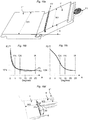
- Figure 4a shows one embodiment of a vertical folding.
- a first panel 1" in a first row R1 is connected to a second 1 panel in a second row R2.
- a new panel 1' is moved with its long edge 5a towards the long edge 5b of first panel 1" at a normal installation angle of about 25-30 degrees, pressed to the adjacent edge and connected with its long edge 5a to the long edge 5b of the first panel with angling.
- This angling action also connects the short edge 4b of the new pane 1' with the short edge 4a of the second panel 1.
- the fold panel 1' is locked to the strip panel 1 with a combined vertical and turning motion along the vertical plane VP.
- the protruding part P2 has a rounded and or angled folding part P2'which during folding cooperates with the sliding surface 23 of the folding panel 1'.
- the combined effect of a folding part P2', and a sliding surface 32 of the tongue which during the folding cooperates with the sliding surface 23 of the fold panel 1' facilitates the first displacement of the flexible tongue 30.
- An essential feature of this embodiment is the position of the projecting portion P2, which is spaced from the corner section 9a and 9b. The spacing is at least 10 % of the length of the joint edge, in this case the visible short edge 4a.
- Figure 4b-c show an embodiment of the set of floor panels with a displaceable tongue and an alternative installation method.
- the length of the tongue is of more than 90% of the width WS of front face of the panel, in other preferred embodiments the length of the tongue is preferably in the range from 75% to substantially the same as the width WS of front face.
- the length of the tongue is about the total width of the panel minus the width of the locking system of the adjacent edges of the panel.
- a small bevel may be provided at the ends of the outer edge, but the straight part of the tongue at the outer edge has preferably a length substantially equal to the length of the tongue or desirable more than 90%.
- the new panel 1' is in angled position with an upper part of the joint edge in contact with the first panel 1" in the first row.
- the short edges 4a and 4b are spaced from each other.
- the new panel 1' is then displaced sideways towards the second panel 1 until the short edges 4a, 4b are essentially in contact and a part of the flexible tongue 15 is pressed into the displacement groove 40 as can be seen in the figure 4b .
- the new panel 1' is then folded down towards the second panel 1. Since the displacement of the new panel 1' presses only an edge section of the flexible tongue 30 into the displacement groove 40, vertical folding will be possible to make with less resistance. Installation could be made with a displaceable tongue that has a straight outer edge.
- a tongue could comprise of plastic material and could be produced with for example injection moulding. With this production method a wide variety of complex three-dimensional shapes could be produced at low cost and the flexible tongues may easily be connected to each other to form tongue blanks.
- a tongue could also be made of an extruded or machined plastic or metal section, which could be further shaped with for example punching to form a flexible tongue. The drawback with extrusion, besides the additional productions steps, is that it is hard to reinforce the tongue, e.g. by fibres.
- polymer materials such as PA (nylon), POM, PC, PP, PET or PE or similar having the properties described above in the different embodiments.
- These plastic materials could, when injection moulding is used, be reinforced with for instance glass fibre, Kevlar fibre, carbon fibre or talk or chalk.
- a preferred material is glass fibre, preferably extra long, reinforced PP or POM.
- Figures 5a - 5e shows embodiments of flexible tongues 30, which could be used to lock short edges.
- Figure 5a shows a separate tongue 30 on the folding panel with a flexible snap tab extending upwards.
- Figure 5b shows a separate tongue 30 on the strip panel with a flexible snap tab extending downwards.
- Figure 5c shows a separate tongue with a flexible snap tab inside a displacement groove 40. The snap tab could extend upwards or downwards and could be on the strip panel or on the folding panel according to the same principles as shown in figures 5a and b.
- Figure 5 d shows a flexible tongue comprising protrusions, as shown in figure 6a and these protrusions could be located in the displacement groove 40 or extend from the vertical plane into the tongue groove 20.
- Figure 5e shows that the tongue 30 could be formed in one piece with the panel and locking could be obtained due to compression of fibres or parts of the panel material and/or bending of the strip 6.
- Figure 6a-c shows embodiments of the tongue 30. They are all configured to be inserted in a groove in a floor panel.
- Figure 6a shows a flexible tongue 30 with flexible protrusions 16.
- Figure 6b shows a bow shaped tongue 30 and figure 6c shows a tongue 30 with a flexible snap tab 17.
- a flexible tongue similar to the embodiment shown in figures 1-4 , 5d 6a and 6b could for example also be produced from a wood fibre based material, for example HDF, solid wood or plywood with several layers. Extremely strong and flexible tongues could be made of HDF especially if the design is such that flexibility is obtained essentially parallel with the fibre orientations of the HDF fibres.
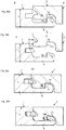
- Figure 7a-d shows in 4 steps installation with vertical folding and problems related to such installation.
- an embodiment is shown with the flexible tongue 30 on the strip panel.
- the tongue could be on the folding panel.
- a new panel 1' is moved in an installation angle with its long edge 5a towards the long edge of a first panel 1" until the upper edges are in contact.
- the new panel is thereafter displaced sideway until the short edge 4b is in contact with a short edge of an adjacent second panel in the same row, as shown in figure 7a .
- the new panel 1' is than angled down to a contact angle when an edge part 30' of the flexible tongue 30 is in a first initial contact with the short edge of the new panel as shown in figure 7b .
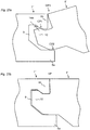
- Figures 8a-8d show in detail the separation problems caused by the flexible tongue 30.
- the panels 1, 1' are according to figure 8a in a contact angle with the sliding surfaces 23, 32 of the folding panel 1' and the flexible tongue in contact.
- Figure 8b and 8c shows that the flexibility of the tongue will create a separation pressure SP which could separate the panels 1, 1' from each other and create a gap G if the panels are not pressed together by the installer.
- Figure 8d shows the panels in locked position with a permanent gap G. In this case the locking strip 6 is bended and the locking element 8 is only partly in the locking groove 14. In the worst case there will be cracks in the locking element 8 and the panels will not be locked horizontally at the short edges.
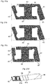
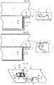
- Figures 9a - 9o shows 3 types of angling locking systems, which are used in large quantities in traditional floorings locked with angling.
- Figures 9a-c show the floor panels in an installation angle A of 25 degrees. In this position there are only two contact points CP3 and CP2 or CP3, CP4 between the first and second connectors. There is always an upper contact point CP3 or contact surface at the upper joint edges and a second lower contact point or contact surface CP4, CP2 on the lower part of the tongue or somewhere between the inner lower part of the tongue 10 and the locking groove 14. The displacement friction along the joint edges is in this position very low especially in HDF based floorings with smooth surfaces.
- Figures 9d-f shows further angling to an angle of 15 degrees and figures 9g-l shows an angle of 10 degrees. In these positions there are still only two contact points and the friction remains low.
- Figures 9j-l shows the position at an angle of 5 degrees, which in these embodiments is the friction angle.
- Figures 9j and 9k show that the locking systems are in a locking angle where the locking surfaces 51,52 are partly in contact.
- Figure 9l shows a locking system in a guiding angle with the guiding surfaces 11,12 in contact.
- Figure 9j shows that this locking system has 4 contact points, two upper contact points at the upper joint edges CP3 and at the upper part of the tongue CP1 and two lower contact points at the lower part of the tongue CP2 and between the locking surfaces CP4.
- Figure 9k shows two upper CP1, CP3 and one lower contact point CP4.
- Figure 9l is similar to figure 9j but one lower contact point is between the guiding surfaces 11, 12.
- the displacement friction along the joint edges will in these positions increase considerably especially if there is a tight fit between the contact points or contact surfaces and/or if the contact surfaces are of a considerable size.
- Pre tension could increase the friction further and a displacement along the long edges in connection with vertical folding could be counteracted and in most cases completely eliminated even in small pieces of floor panels.
- Such locking systems are however not suitable on the long side in a vertical folding system where the contact angle is higher than 5- 8 degrees, especially if they are produced with a normal fit between the connectors, since they will not prevent displacement along the long edges and separation of the short edges.
- Figure 10a shows an embodiment according to the first object.
- a locking system could preferably be used on the long edges in a vertical folding system with a contact angle A of about 10 degrees and lower. It will also be possible to use such a system in locking systems with a higher contact angle since such system will prevent displacement already at 10 degrees when most fold down locking systems create the highest displacement pressure.
- Figure 10a show the position of panel 1' at an angle of 15 degrees when only two points CP3, CP2 are in contact. The panel 1' is in a friction angle position of 12 degrees with three contact points CP3, CP2, CP4'. This position is characterized by the fact that there is only one contact point CP2 on the tongue and that the guiding surfaces 11,12 are in contact.
- the ideal position is preferably an embodiment with a contact angle equal or lower than the friction angle and the guiding angle.
- Such embodiment could for example have a friction and guiding angle of about 10 degrees and a contact angle of about 8-9 degrees.
- the locking could be made in an extremely simple way and only a downward pressure on the new panel has to be applied when the panel is positioned at a guiding angle.
- Figure 10c show that the locking system is configured with a high angle between the locking surfaces and that fibres during the final stage of angling, shown by the position l'a, must be compressed at top edges CP4 and at locking surfaces CP4 in order to allow locking.
- This configuration gives several advantages.
- the friction will increase and be at a high level when the separation force is at the highest level.
- the floor panels will be maintained in an angled up position by the locking element and the locking groove, as shown in figure 10b independently or in combination with a contact between the short edge of the folding panel and an edge section of the flexible tongue. The friction will prevent the short edge to slide away from the flexible tongue. This will facilitate installation since the installer could change the hand position from bringing the panel into the installation angle to a vertical pressing action at the short edge.
- the example therefore provides a vertical locking system with a long edge angling system that allows one panel to stay in an angled position against another panel with upper joint edges in contact. It also provides a locking system where there is an increasing pressure between the upper joint edges and the locking element and/or between the tongue and the groove in an final stage of angling when the a part of the locking groove 14 is in contact with the locking element 8.
- Figures 11a-11c show that the same principles could be used to form a locking system with an even higher friction angle A of for example 15 degrees as shown in figure 11a .
- the locking element 8 has been made higher and it extends in this preferred embodiment vertically LH from the lowest point of the locking strip 6 about 0,2 times the floor thickness T.
- the tongue has a lower part 54, which is essentially parallel with the horizontal plane HP and which extends from the vertical plane VP preferably along a distance TD of about 0,1 times the floor thickness T.
- Figure 12a shows a long edge locking system 1", 1' and a short edge locking system 1,1' in an installed flooring system which is intended to be locked with vertical folding or vertical locking.
- the long edges have a locking system that is possible to lock with angling.
- the short edges have a locking system that is possible to lock with vertical locking or vertical folding
- Figure 12b shows the position of the sliding surface 23 of for example a new panel 1' seen from a second panel 1 towards the new panel 1' when the new panel 1' is moved vertically downwards. This locking could be used to for example connect the first row.
- the sliding surface 23 is in a plane which is located in the lower part of the panel 1'
- Figure 12c shows the position of sliding surface 32, the tip 31 of the flexible tongue and the sliding surface 23 when the first 1", and the second panel 1 are laying flat on the floor.
- Figures 12b and 12c show that position of the flexible tongue in the length direction of the short edge is not important in a vertical locking where the whole panel is moved vertically downwards.
- Figure 13a shows an embodiment of the same locking system as in figures 12 during vertical folding
- the edge of a flexible tongue 30 is in this embodiment positioned at a distance FD from the long edge of the first panel 1"
- Figure 13b shows vertical folding of a corner section CS and the position of the new panel 1' when it is close to a contact angle. Due to the bevelled sliding surfaces 23, 32 there is not yet any contact between the folding panel 1' and the flexible tongue 30.
- Figure 13c shows the contact angle, which in this embodiment is 10 degrees.
- the sliding surfaces 32,23 overlap each other at an initial contact point CP5.
- Figure 14a and 14b shows the position of the flexible tongue 30 in two embodiments.
- the flexible tongue 30 is in these embodiments bendable in the length direction horizontally.
- the edge of the flexible tongue is in the figure 14a located in a position FD1 close the long edge 5b, for example about 15 mm from the edge.
- Such a locking system will in a laminate floor with a normal thickness have a contact angle of about 10 degrees.
- the contact angle could be lower if the edge of the tongue will be positioned at a distance FD2 further away from the long edge 5b as shown in figure 14b . In this case locking systems with a lower contact angle could be used.
- Such an embodiment could be sufficient in thick and stable floor panels or narrow floor panels.
- FIGS 14c and 14d show the flexible tongue in an essentially contact position when a first part of the flexible tongue 30 has been bended horizontally and pressed horizontally inwards into the displacement groove. It is obvious that the separation pressure will increase when a larger part of the tongue is bended and pressed horizontally sideways during the folding action.
- Figures 15a-c show friction means 53,53' which in this embodiment are formed as small local protrusions on the upper part of the locking strip 6 on the strip panel 1 and on the lower part of the tongue or on the groove panel 1'.
- Such protrusions could be formed on other surfaces in the locking system and they will prevent displacement at high angles for example when there are only two contact points as shown in figure 15a .
- the friction means could also comprise any type of materials or chemicals such as small hard particles, rubber, binders and similar materials that are applied in the locking system.
- Preferred materials are soft waxes such as Microcrystalline waxes or paraffin based waxes which could be applied on one or several surfaces in the locking system, for example on the tongue and or the tongue groove, on the strip, on the locking element and/or in the locking groove, on one or both guiding surfaces etc. and they could increase the initial friction between especially HDF surfaces.
- soft waxes such as Microcrystalline waxes or paraffin based waxes which could be applied on one or several surfaces in the locking system, for example on the tongue and or the tongue groove, on the strip, on the locking element and/or in the locking groove, on one or both guiding surfaces etc. and they could increase the initial friction between especially HDF surfaces.
- a plywood core different layers and fibre structure could be used to form a tongue 10 and a strip 6 such that high friction is obtained during angling.
- the above mentioned friction means could be combined.
- Local small protrusions, rough surfaces, oriented fibre structures etc. could for example be combined with wax or chemicals
- Figures 16a-d show methods
- a sample of a groove panel 1' with a width W2 of about 200 mm is pressed with a pressure force F1 of 10 N at an angle A against a strip panel 1", which is fixed and has a with W1 exceeding 200 mm.
- the pressure force F1 is applied on the groove panel 1'with a wheel which rotates with low friction.
- the displacement friction is defined as the maximal force F2 which is required to displace the groove panel 1'along the joint.
- the curve Fa in Figure 16b shows measurements made on a sample of a 8 mm laminated panel with a surface of printed paper impregnated with thermosetting resins and with a HDF core. Friction should be measured from an installation angle and gradually at lower angles.
- the displacement friction of this sample is at an installation angle IA about 10 N and almost the same at a contact angle CA of 10 degrees.
- the friction angle FA is in this sample about 5 degrees.
- Many HDF based locking systems on the market have a displacement friction below 10 N at the installation angle.
- the friction could be as low as 5 N.
- the long edges will in such locking system only contribute marginally to counteract displacement of the short edges during the initial stage of the vertical folding since the friction angle is lower than the contact angle.
- the curve Fb shows a special locking system where the friction, due to the geometry of the locking system, at an installation angle is higher than at a lower angle.
- the embodiment is based on the principle that friction should be increased at the contact angle compared to a installation angle or any other angle between the installation angle and the contact angle where the friction force is at the lowest level.
- a preferred embodiment is that the friction at the contact angle exceeds 15 N and still more, preferable 20 N.
- a preferred embodiment is also a vertical locking system with a flexible tongue that creates a tongue pressure of more than 20 N, even more than 30 N There are locking systems on the market that show rather high friction at high angles.
- Such locking systems are not possible to angle down from an installation angle to a contact angle or a guiding angle in a normal way with a pressure F1 of 10 N, which corresponds to a 60 N pressure force applied to a floor panel of 120 cm during installation and they are a type of locking systems where angling must be combined with very hard pressure or a snap action in an angled position.
- Such locking systems are not used in vertical folding systems. They are not favourable in an vertical folding system since they will only marginally, in some specific applications, improve installation compared to the traditionally used installation with angling short and long edges, snapping short and long edges or angling long edges and snapping short edges.
- Figure 16c shows a more favourable locking system where the friction angle FA is about 15 degrees and the contact angle CA 10 degrees.
- the friction angle FA is higher than the contact angle CA and the friction between the long edges has increased considerably at the contact angle CA compared to the installation angle IA.
- Figure 16d shows how two samples 1, 1' with a width W3 of 200 mm are installed and according to the forth principle, such an installation should not cause a separation of the short edges when the folding panel is pressed to the sub floor, exclusively vertically and without any sideways pressure towards the short edge.
- the test could also be made with one full size panel 1 and one panel 1' cut to a length of about 20 cm.
- Such locking system with a long edge friction that prevents displacement of such small floor pieces, will allow an easy installation, not only of the ordinary floor panels but also of all the cut to size floor panels close to the wall.
- Figure 17a-c show how the locking system in figure 11 could be adjusted in order to create a friction with initially three contact points CP3, CP1 and CP4.
- the friction is mainly obtained by the pressure between the locking element 8/locking groove 14 and the upper part of the tongue 10/ tongue-groove 9.
- the tongue has in this embodiment a lower part 54 which is essentially parallel with the horizontal plane HP and which extends from the vertical plane preferably along a shorter distance TD than in figure 11 and which is less than 0,1 times the floor thickness T.
- Figure 18a-18c show that the locking system in figure 11 could also be adjusted in order to create a friction with initially three other contact points CP3, CP1 and CP3.
- the friction is mainly obtained by the pressure between the upper and lower parts of the tongue 10/tongue groove 9.
- the tongue has in this embodiment a lower part 54 which is essentially parallel with the horizontal plane HP and which extends from the vertical plane preferably along a the same distance TD as in figure 11 .
- the height LH of the locking element is however lower.
- Friction means 53 are shown in the form of wax, on the lower part on the tongue 10.
- the wax should preferably be rather soft and it should preferably be possible to deform during the angling. This soft wax will prevent initial displacement along the joint. Such wax could be applied in all locking system and it would prevent displacement especially against surfaces made of HDF.
- Figure 17 and 18 show that a lot of combinations of friction angles and friction points could be obtained if the dimensions of the tongue 10, groove 9, strip 6 locking element 8 and the locking groove 14 are adjusted.
- Figure 19a shows an embodiment with a friction angle of 20 degrees where the friction is obtained with only two contact points CP1 and CP2 between the upper and lower parts of the tongue 10/ tongue-groove 9.
- the tongue has in this embodiment also a lower part 54, which is essentially parallel with the horizontal plane HP, and which extends from the vertical plane along a distance TD of more than 0,2 times the floor thickness T.
- the tongue has in this embodiment a space 55 between the lower part of the tongue and the tongue groove which facilitates the locking and allows that the guiding surfaces 11,12 are overlapping at a high angle of for example 15 degrees as shown in figure 19b .
- Figure 20a-c show that it is possible to design a locking system with three contact points CP3, CP1 and CP2 at an installation angle of 25 degrees as shown in figure 20a .
- the locking element has been made even higher (LH) than in the previous embodiments and the groove panel 1' has a protrusion 56 between the tongue 10 and the tongue groove 9.
- the upper portion of the tongue has an angle against the horizontal plane and this facilitates machining with large rotating tools of the tongue groove 9.
- a simple vertical locking on the short edge does not give any major improvement over the present technology if it is not combined with a well functioning long edge locking system with superior guiding and locking properties that allow a connection of long and short edges with a simple angling action.
- the only action, which is than required to lock the panels, is a vertical pressing on the folding panel close to the short edges.
- an installation method of three panels is provided, where the first 1'' and the second panel 1 is laying flat on the sub floor with the long edges connected to each other as for example shown in figure 7a .
- the method comprises the steps of
- This installation method allows that floor panels will be maintained in an angled up position by for example the guiding surfaces 11,12 as shown in figure 10 .
- This will facilitate installation since the installer could change hand position from a first position where the panel is brought into an installation angle of 25 degrees, pressed towards the edge of the already installed first panel 1" and preferably angle down slightly to the friction and guiding angle.
- the installer can then move his hands to a second position suitable to press down preferably both short edge section of panel towards the sub floor.
- the guiding surfaces will guide the locking element into the locking groove and the tongue in the tongue groove.
- the friction between long edges will prevent displacement.
- FIGS 21a - c show a flexible tongue 30 with an inner 62 and an outer 61 flexible part.
- Flexible tongues as shown in figures 5a- 5c suffers from the following disadvantages
- Figure 21b shows that an extruded tongue made of for example plastic or metal could be equalized by for example machining or grinding. This will improve production tolerances considerably to a level similar to injection moulding or even better. Displacement, locking function and locking strength could be improved considerably.
- the lower contact surface 64 and/or the locking surface 65 has been equalized prior to the insertion into the displacement groove 40.
- a part of the flexible tongue, preferably the outer flexible part 61 could be equalized when the tongue is or has been connected to the edge. This could be obtained in a separate production step or in line when the locking system is formed.
- the flexible tongue could be designed such that it bends horizontally in the length direction during vertical folding.
- Such bending will be facilitated and separation forces will be reduced if a tongue section 68 at an edge as shown in figure 21d is removed.
- Such tongue section could also be removed from the inner resilient part 67 and the tongue will bend in the length direction with less resistance and facilitate the vertical folding.
- Such forming with a cut of part at an edge section could be made in all types of extruded tongues especially in such tongues that have a limited flexibility, for example the embodiment with only one outer resilient or flexible part as shown in figures 5a, 5b and 6c .
- the flexible tongue could also be designed according to the hinge principle with a rigid protrusion and a flexible knee joint such that it does not bend horizontally during locking. Such embodiment could give a strong locking.
- aspects comprise also a separate extruded flexible tongue designed to be used for vertical locking of floorboard characterized in that such a tongue has been equalized preferably on an upper 63 and/or lower 64 contact surface and/or on a locking surface 65.
- a tongue and the above described tongue with a removed edge section could also have a shape similar to the shapes shown in figures 5a-5c where the flexible tongue comprises only an inner or an outer flexible snap tab.
- Machining, grinding and similar production steps will generally create a surface that differs from the extruded virgin surface. This could in most cases be detected in a microscope. Such machining could also be used to increase or decrease friction between the tongue and the displacement groove.
- Figures 22a-22c shows vertical folding or vertical locking.
- One panel 1' is moved preferably along the vertical plane VP towards another panel 1.
- the inner flexible part 62 will be bended vertically when an edge section of the folding panel 1' comes in contact with an outer part of the flexible tongue 30, preferably the outer flexible part 61, and the flexible tongue will be displaced inwardly into the displacement groove 40 where it is connected preferably with a friction connection. Gradually even this outer flexible part 61 will start to bend as shown in figure 22b .
- both the inner 62 and the outer parts 62 will snap back towards its initial positions and the flexible tongue will be displace in the displacement groove 40 towards the tongue groove 20.
- the locking surface 65 of the flexible tongue 30 will lock against a part of a tongue groove 20.
- connection between the tongue and the displacement groove could be made with a small play allowing easy displacement and some tilting of the tongue during locking.
- the outer flexible part 61 is preferably during locking mainly displaced horizontally with a minor turning around the upper knee 70.
- the lower contact surface 65 could be made with an angle, which is preferably less than 10 degrees against the horizontal plane and this will increase the locking strength.
- Figure 23a show a tongue lock system, which could be locked with angling.
- the new panel 1' has a first connector comprising a tongue 10 with a locking element 8a at the upper part.
- the first panel 1" has an undercut tongue groove 9 with an upper 6b and lower 6b lip and a locking groove 14a formed in the upper lip 6b and extending downwards towards the lower lip 6a.
- the first and second connectors lock the panels vertically and horizontally.
- the lower lip 6a extends preferably beyond the vertical plane VP and has preferably a horizontal contact surface, which is in contact with a lower part of the tongue 10.
- the locking system could for example be designed such that it has three contact points CP1,2,3 at an angle exceeding 15 degrees as shown in figure 23a .
- the tongue lock could be used as an alternative to the strip lock systems in all embodiments described above.
- a tongue lock on long edges could be combined with a hook system on the short edges, which preferably only locks horizontally as shown in figure 24d .
- Figure 24a shows a locking system with a double tongue 10, 10' and two corresponding tongue grooves 9,9'which could be used to lock the long edges with angling, snapping or even vertical locking if the tongues and the strip is adjusted to allow a vertical snap action.
- Such system could have more than four contact points and the friction along the joint could be considerable.
- Figure 24b shows a locking system with a separate strip 6' which also could be used to lock the long edges in the same way as the embodiment in figure 24a .
- a strip could comprise a material or a surface that has more favourable friction properties than the core material.
- Figure 24c shows a locking system with a separate tongue 10' that could be flexible or rigid and that could be connected to the strip panel 1" or the folding panel 1' on long and/or short edges in order to improve friction properties or to save material.
- Figure 24d shows a hook system, which only locks horizontally.
- Figure 24e show an embodiment of a locking system with a flexible tongue 30 made in one piece with the core, in accordance with the invention.
- An undercut groove 71 which is formed behind the flexible tongue 30, could increase the flexibility of the tongue.
- Such a groove could be formed, preferably by a scraping tool, when the short edges are machined.
- scraping or broaching technology could be used to form advanced shapes similar to extruded plastic sections especially in fibre-based material such as HDF but even in solid wood and plastic materials.
- the flexible tongue 30 could also be formed with large rotating tools on the folding panel 1' with an outer part that extend upwards.
- the locking system could also have two flexible tongues - one on each edge.
- Wood fibres in the flexible tongue could be impregnated and/or coated with for example a binder 70 in order to increase the strength and flexibility. Impregnation could be made prior or after the forming of the tongue or the edge.
- the whole edge or parts of the locking system for example the tongue groove 20, the locking element 8 or the locking groove 14 could also be impregnated and/or coated.
- the undercut groove could be filled with flexible materials in order to improve strength and flexibility. Vertical folding could be facilitated if the strip 6 and/or the locking element 8 could flex during the vertical folding. Wax in the locking system will facilitate locking.
- a essentially vertical groove 73, above the strip in the folding panel 1' or a cavity 72 in the strip 6 adjacent to the locking element 8 in the strip panel1 1 will increase the flexibility of the locking further system and allow parts to be more flexible.
- Parts 78 of the lower side of the strip and/or balancing layer could be removed and this could increase the flexibility of the strip and allow easier bending towards the sub floor.
- the folding panel could have a protrusion 74 and preferably also locking surfaces of the type as described in figure 27c .
- the flexible tongue could also be formed from a separate material, which is fixed connected to the panel by for example gluing, friction or snapping.
- Such separate material could for example be a rather local edge portion 77 that could be connected to the edge prior to the final machining.
- the undercut groove 71 could also be preformed before the separate material 77 is connected to the edge of the panel. Such a connection could be made on individual panel edges or to a panel board that is thereafter cut to individual floor panels.
- the separate material 75, 76 could also be connected to the edge of the strip panel 1 and/or the folding panel 1' such that it comprises a major parts of the locking system.
- Such separate material could in a wood floor preferably be glued to the upper top layer and the lower balancing layer.
- Separate materials could comprise of for example solid wood which is preferably hard and flexible such as rubber wood or birch, wood impregnated with binders, for example acrylic binders, plastic materials, compact laminate made of wood fibre material and phenol which also could comprise glass fibre, HDF or HDF reinforced by binders, HDF with essentially a vertical fibre orientation, materials with several layers comprising wood fibres and/or plastic materials and/or glass fibre. Such materials could be used separately or in combinations.
- the locking system could of course also be made according to the principles described above without the undercut groove 71, for example according to the embodiment described in figure 5e if appropriate materials and joint configurations are used to allow the required flexibility.
- a lot of chemicals could be used to impregnate or to coat parts or the whole locking systems such as melamine, urea, phenol, thermoplastic materials such as PP or PUR. Such chemicals could be cured with for example heat, microwave, UV or similar with or without pressure.
- the flexible tongue 70 could in a standard HDF material flex a few tenths of a millimetre and this could be sufficient to obtain a vertical locking especially in a laminate floor. Impregnation and/or coating could increase this flexibility considerably
- a preferred embodiment comprising a short edge locking system is provided that could be locked with vertical folding or vertical locking, characterized in that the locking system comprises an edge with a strip 6, a locking element 8, a flexible tongue 30 extending downwards and formed in one piece with a panel core or in a separate material which iud connected in a fixed manner to the core.
- the flexible tongue 30 comprises an undercut groove 70 formed behind the tongue.
- Figures 25a-c shows how the highest three point contact angle could be correctly determined in a locking system mainly made in a wood fibre based core material.
- a locking system mainly made in a wood fibre based core material.
- a sample with a width W2 and length of about 100 mm is angled down from an installation angle with top edges in contact until a resistance occurs from the contact between the locking groove and the locking element. The sample should in this position, which is the highest three point contact angle, be able to maintain it's up angled position and it should not fall down to the sub-floor due to the weight of the sample.
- Such a locking system has a design, which is characterized in that the three points are the upper edges CP3, the upper part of the tongue and the groove CP1 and the locking element/locking groove CP4.
- a locking system could however have a design as showed in figures 25b ,c where the three contact points are the upper and lower parts of the tongue together with top edges (CP1, CP2, CP3).
- Some of such locking systems will however not stand up in an up angled position. In such systems a cross section of a joint should be analysed in a microscope. If lose fibres makes it difficult to define a three point contact angle, friction should be measured as described in figure 16 . Increased friction is an indication that an additional contact point is active in the locking system.
- Figures 26a-26d shows an embodiment of a locking system at the short edges that counteracts or prevents displacement of the long edges during vertical folding.
- Figure 26a show a cross section B-B of a short side locking system close to the edge part where the folding starts, as shown in figure 4a .
- This locking system as described before in connection to for example the figures 1-3 , 5 , and 8 , comprises a strip 6 with a locking element 8 and a separate flexible tongue 30 in a strip panel 1, a tongue groove 20 and a locking groove 14 in the folding panel 1'.
- the locking surfaces are essential vertical and parallel with the vertical plane VP.
- this locking system could be designed such that the locking element 8 with its upper part of the locking surface 8a is in contact with the lower part of the locking surface 14a of the locking groove 14 as shown in figure 26a , when there are no contacts between the fold panel 1' and the flexible tongue 30.
- This could be accomplished due to the fact that there is no tongue part close to the long edge or that the tongue is bow shaped and has no protruding part that is in contact with the folding panel 1'.
- Figure 26b shows a cross cut at C-C in figure 4a .
- the locking surfaces 8a,14a will prevent separation when the tongue 30 is in contact with the fold panel provided that they are essentially and preferably completely vertical and that they extend vertically along a considerable distance so that they could prevent displacement at a angle of preferably 10 degrees or higher, even in an embodiment where the flexible tongue 30 is positioned close to the long edge.
- the locking surfaces should preferably have a height H which is at least 0,1 or even more than 0,15 time the floor thickness T. Vertical locking surfaces could also be made with a height H of about 0,2*T or more.
- Figure 26d shows that the function could be equivalent if only the locking surface 14a of the locking groove 14 meets the requirements above.
- the function could also be the same if the locking groove 14b is for example bow shaped towards the outer edge, provided that there are at least two parts which are located vertically along a vertical plane and that the distance is about 0,1*T.
- Figure 27a shows an embodiment where the locking element 8 and the locking groove 14 on the short edge is used to prevent separation. It is an advantage if the edge 8a of the locking element 8 is located close to the long edge 5b of the first panel 1" since this edge will grip into the locking groove of the new panel at a rather high angle and the flexible tongue could be positioned such that it locks close to the long edge.
- the flexible tongue 30 is in this embodiment an extruded section with a cut of edge section 68 that facilitates horizontal displacement during folding. High and vertical locking surfaces on the short edges are especially suitable in locking systems with a flexible tongue comprising an extruded plastic section and especially if such a section has only one outer flexible snap tab that due to limited flexibility causes a considerable separation pressure.
- Figure 27 shows that the flexible tongue 30 could be moved even further towards the long edge 5b and prevent displacement along the long edge at an even higher angle if a compact tongue lock system is used on the long edges since such a locking system does not comprise a strip 6a protruding far beyond the vertical plane VP.
- Figure 27c show a locking system with a preferably extruded and flexible tongue 30 and essentially vertical locking surfaces between the locking element 8 on the strip 6 and the locking groove 14 in the folding panel 1'.
- the folding panel 1' comprises a protrusion 74 adjacent to the locking surface of the locking groove 14 that is received in a adjacent cavity 72 on the strip 6 and preferably an essentially horizontal lower contact surface 24 that locks vertically against an adjacent strip contact surface 6'.
- This configuration is very suitable in flooring with a HDF core since the cavity is formed in the lower part of the core where the density is high. The cavity will only to a limited extent decrease the strength of the locking system.
- the height H of the vertical locking surfaces is preferably at least 0,1*T.
- the design of the locking system is preferably such that the locking element 8 is located below a horizontal plane H2 that comprises the lower part of the displacement groove 40 and the locking groove 14 is located under a horizontal plane H1 that comprises the inner part and lowest part of the tongue groove 20.
Priority Applications (2)
| Application Number | Priority Date | Filing Date | Title |
|---|---|---|---|
| EP21192158.0A EP3971368A1 (en) | 2006-11-15 | 2007-10-25 | Mechanical locking of floor panels with vertical folding |
| PL18209535T PL3540146T3 (pl) | 2006-11-15 | 2007-10-25 | Mechaniczne blokowanie paneli podłogowych ze składaniem w pionie |
Applications Claiming Priority (5)
| Application Number | Priority Date | Filing Date | Title |
|---|---|---|---|
| US85896806P | 2006-11-15 | 2006-11-15 | |
| SE0602429A SE532607C2 (sv) | 2006-11-15 | 2006-11-15 | Mekanisk låsning av golvpaneler med vertikal vikning |
| EP07835365A EP2082103B1 (en) | 2006-11-15 | 2007-10-25 | An installation method to connect floor panels in rows by vertical folding |
| PCT/SE2007/050781 WO2008060232A1 (en) | 2006-11-15 | 2007-10-25 | Mechanical locking of floor panels with vertical folding |
| EP12196884.6A EP2570565B1 (en) | 2006-11-15 | 2007-10-25 | Mechanical locking of floor panels with vertical folding |
Related Parent Applications (2)
| Application Number | Title | Priority Date | Filing Date |
|---|---|---|---|
| EP12196884.6A Division EP2570565B1 (en) | 2006-11-15 | 2007-10-25 | Mechanical locking of floor panels with vertical folding |
| EP07835365A Division EP2082103B1 (en) | 2006-11-15 | 2007-10-25 | An installation method to connect floor panels in rows by vertical folding |
Related Child Applications (1)
| Application Number | Title | Priority Date | Filing Date |
|---|---|---|---|
| EP21192158.0A Division EP3971368A1 (en) | 2006-11-15 | 2007-10-25 | Mechanical locking of floor panels with vertical folding |
Publications (2)
| Publication Number | Publication Date |
|---|---|
| EP3540146A1 EP3540146A1 (en) | 2019-09-18 |
| EP3540146B1 true EP3540146B1 (en) | 2021-08-25 |
Family
ID=39401945
Family Applications (3)
| Application Number | Title | Priority Date | Filing Date |
|---|---|---|---|
| EP12196884.6A Active EP2570565B1 (en) | 2006-11-15 | 2007-10-25 | Mechanical locking of floor panels with vertical folding |
| EP07835365A Active EP2082103B1 (en) | 2006-11-15 | 2007-10-25 | An installation method to connect floor panels in rows by vertical folding |
| EP18209535.6A Active EP3540146B1 (en) | 2006-11-15 | 2007-10-25 | Mechanical locking of floor panels with vertical folding |
Family Applications Before (2)
| Application Number | Title | Priority Date | Filing Date |
|---|---|---|---|
| EP12196884.6A Active EP2570565B1 (en) | 2006-11-15 | 2007-10-25 | Mechanical locking of floor panels with vertical folding |
| EP07835365A Active EP2082103B1 (en) | 2006-11-15 | 2007-10-25 | An installation method to connect floor panels in rows by vertical folding |
Country Status (5)
| Country | Link |
|---|---|
| EP (3) | EP2570565B1 (pl) |
| KR (1) | KR101468444B1 (pl) |
| CA (1) | CA2669105C (pl) |
| PL (2) | PL2082103T3 (pl) |
| WO (1) | WO2008060232A1 (pl) |
Families Citing this family (45)
| Publication number | Priority date | Publication date | Assignee | Title |
|---|---|---|---|---|
| JP4472355B2 (ja) | 2002-04-03 | 2010-06-02 | ベーリンゲ、イノベイション、アクチボラグ | フロアボード用機械式係止システム |
| US7841144B2 (en) | 2005-03-30 | 2010-11-30 | Valinge Innovation Ab | Mechanical locking system for panels and method of installing same |
| SE533410C2 (sv) | 2006-07-11 | 2010-09-14 | Vaelinge Innovation Ab | Golvpaneler med mekaniska låssystem med en flexibel och förskjutbar tunga samt tunga därför |
| US8689512B2 (en) | 2006-11-15 | 2014-04-08 | Valinge Innovation Ab | Mechanical locking of floor panels with vertical folding |
| US11725394B2 (en) | 2006-11-15 | 2023-08-15 | Välinge Innovation AB | Mechanical locking of floor panels with vertical folding |
| SE531111C2 (sv) | 2006-12-08 | 2008-12-23 | Vaelinge Innovation Ab | Mekanisk låsning av golvpaneler |
| EP3483357A1 (en) | 2007-11-07 | 2019-05-15 | Välinge Innovation AB | Set of floor panels comprising a mechanical locking system for vertical snap folding |
| US8353140B2 (en) | 2007-11-07 | 2013-01-15 | Valinge Innovation Ab | Mechanical locking of floor panels with vertical snap folding |
| EP3597837B8 (en) | 2008-01-31 | 2021-08-04 | Välinge Innovation AB | Method to produce a mechanical locking of building panels |
| US8505257B2 (en) | 2008-01-31 | 2013-08-13 | Valinge Innovation Ab | Mechanical locking of floor panels |
| WO2009139687A1 (en) | 2008-05-15 | 2009-11-19 | Välinge Innovation AB | Floor panels with a mechanical locking system activated by a magnetic field and a method to install the panels |
| SE532679C2 (sv) * | 2008-10-27 | 2010-03-16 | Micael Johansson | Förfarande för lagning och en anordning för genomförande därav |
| US8713886B2 (en) | 2009-01-30 | 2014-05-06 | Valinge Innovation Ab | Mechanical lockings of floor panels and a tongue blank |
| DE102009040114A1 (de) | 2009-03-03 | 2010-09-16 | Fritz Egger Gmbh & Co. | Paneel zur Bildung eines Belags und Verfahren zur Herstellung eines solchen Paneels |
| BE1018728A3 (nl) | 2009-04-22 | 2011-07-05 | Flooring Ind Ltd Sarl | Vloerpaneel. |
| NL2003019C2 (nl) | 2009-06-12 | 2010-12-15 | 4Sight Innovation Bv | Vloerpaneel en vloerbedekking bestaande uit meerdere van dergelijke vloerpanelen. |
| CN102695838B (zh) | 2010-01-12 | 2016-01-20 | 瓦林格创新股份有限公司 | 地板镶板的机械锁定系统 |
| EP3524754B1 (en) | 2010-01-14 | 2020-10-28 | Unilin, BV | Floor panel assembly |
| CN102725464B (zh) | 2010-02-04 | 2015-01-07 | 瓦林格创新股份有限公司 | 用于地板镶板的机械锁定系统及其榫舌 |
| DE102010012572B3 (de) * | 2010-03-23 | 2011-07-14 | Fritz Egger Gmbh & Co. Og | System von wenigstens zwei Paneelen |
| BR112012025923B1 (pt) | 2010-04-15 | 2019-08-27 | Spanolux N V Div Balterio | montagem do painel de piso, painel de piso e elemento de trava |
| BE1019331A5 (nl) | 2010-05-10 | 2012-06-05 | Flooring Ind Ltd Sarl | Vloerpaneel en werkwijzen voor het vervaardigen van vloerpanelen. |
| DE102010021436A1 (de) * | 2010-05-25 | 2011-12-01 | Hamberger Industriewerke Gmbh | Verbindung für zwei Paneele |
| UA109938C2 (uk) | 2011-05-06 | 2015-10-26 | Механічна фіксуюча система для будівельних панелей | |
| UA114715C2 (uk) | 2011-07-05 | 2017-07-25 | Сералок Інновейшн Аб | Механічна фіксація панелей настилу підлоги до язичка з нанесеним шаром клею |
| US9725912B2 (en) | 2011-07-11 | 2017-08-08 | Ceraloc Innovation Ab | Mechanical locking system for floor panels |
| EP3567185B1 (en) * | 2011-07-11 | 2023-06-14 | Ceraloc Innovation AB | Mechanical locking system for floor panels |
| US8650826B2 (en) | 2011-07-19 | 2014-02-18 | Valinge Flooring Technology Ab | Mechanical locking system for floor panels |
| US8769905B2 (en) | 2011-08-15 | 2014-07-08 | Valinge Flooring Technology Ab | Mechanical locking system for floor panels |
| US8857126B2 (en) | 2011-08-15 | 2014-10-14 | Valinge Flooring Technology Ab | Mechanical locking system for floor panels |
| US8763340B2 (en) | 2011-08-15 | 2014-07-01 | Valinge Flooring Technology Ab | Mechanical locking system for floor panels |
| MY175339A (en) * | 2011-08-29 | 2020-06-19 | Valinge Flooring Tech Ab | Mechanical locking system for floor panels |
| EP2570564A3 (en) * | 2011-09-16 | 2014-08-20 | Spanolux N.V. Div. Balterio | An apparatus and a method for assembling panels and locking elements |
| CN104160101B (zh) | 2012-02-07 | 2017-06-23 | 地板工业有限公司 | 用于形成地板覆层的地板镶板,由这种地板镶板形成的地板覆层以及制造这种地板镶板的方法 |
| US8596013B2 (en) | 2012-04-04 | 2013-12-03 | Valinge Innovation Ab | Building panel with a mechanical locking system |
| US9216541B2 (en) | 2012-04-04 | 2015-12-22 | Valinge Innovation Ab | Method for producing a mechanical locking system for building panels |
| CA2892212C (en) | 2012-11-22 | 2020-06-30 | Valinge Flooring Technology Ab | Mechanical locking system for floor panels |
| PL3613919T3 (pl) | 2013-06-27 | 2023-01-30 | Välinge Innovation AB | Panel budowlany z mechanicznym układem blokującym |
| CN110453881B (zh) | 2014-05-14 | 2021-07-13 | 瓦林格创新股份有限公司 | 具有机械锁定系统的建筑面板 |
| US10246883B2 (en) | 2014-05-14 | 2019-04-02 | Valinge Innovation Ab | Building panel with a mechanical locking system |
| EP3224427B1 (en) | 2014-11-27 | 2019-09-11 | Välinge Innovation AB | Set of essentially idencial floor panels with mechanical locking system |
| SI3031998T1 (en) * | 2014-12-08 | 2018-04-30 | Innovations4Flooring Holding N.V. | Panel with hook-up locking system |
| KR101627469B1 (ko) | 2015-10-08 | 2016-06-07 | (주)동주산업 | 상판 분리형 마루판의 제조방법 및 이에 의해 제조된 상판 분리형 마루판 |
| NL2018781B1 (en) | 2017-04-26 | 2018-11-05 | Innovations4Flooring Holding N V | Panel and covering |
| US11060302B2 (en) | 2019-01-10 | 2021-07-13 | Valinge Innovation Ab | Unlocking system for panels |
Family Cites Families (16)
| Publication number | Priority date | Publication date | Assignee | Title |
|---|---|---|---|---|
| JPH0657926A (ja) * | 1992-08-06 | 1994-03-01 | Eidai Co Ltd | 遮音床板 |
| BE1010487A6 (nl) * | 1996-06-11 | 1998-10-06 | Unilin Beheer Bv | Vloerbekleding bestaande uit harde vloerpanelen en werkwijze voor het vervaardigen van dergelijke vloerpanelen. |
| EP1190149B1 (de) * | 1999-06-30 | 2004-01-21 | Akzenta Paneele + Profile GmbH | Paneel sowie befestigungssystem für paneele |
| DE10001076C1 (de) * | 2000-01-13 | 2001-10-04 | Huelsta Werke Huels Kg | Paneelelement |
| DE20112474U1 (de) * | 2001-07-28 | 2002-12-19 | Kaindl Wals M | Paneel, beispielsweise für Fußboden-, Wand- und/oder Deckenverkleidungen |
| DE20122778U1 (de) | 2001-08-10 | 2007-10-25 | Akzenta Paneele + Profile Gmbh | Paneel sowie Befestigungssystem für Paneele |
| DE10214972A1 (de) * | 2002-04-04 | 2003-10-30 | Akzenta Paneele & Profile Gmbh | Paneel sowie Verriegelungssystem für Paneele |
| DE50311595D1 (de) * | 2002-04-05 | 2009-07-30 | Tilo Gmbh | Fussbodendielen |
| EP1497510B2 (en) * | 2002-04-22 | 2008-12-24 | Välinge Innovation AB | Flooring |
| DE10231921A1 (de) * | 2002-06-28 | 2004-01-22 | E.F.P. Floor Products Fussböden GmbH | Paneel eines Fußbodensystems, insbesondere eines Laminatfußbodens |
| PL191233B1 (pl) * | 2002-12-31 | 2006-04-28 | Barlinek Sa | Panel podłogowy |
| SE526691C2 (sv) * | 2003-03-18 | 2005-10-25 | Pergo Europ Ab | Panelfog med friktionshöjande medel vid långsidans vridfog |
| US7841144B2 (en) * | 2005-03-30 | 2010-11-30 | Valinge Innovation Ab | Mechanical locking system for panels and method of installing same |
| DK1650375T4 (da) * | 2004-10-22 | 2011-02-28 | Vaelinge Innovation Ab | Sæt af gulvpaneler |
| DE102004054368A1 (de) * | 2004-11-10 | 2006-05-11 | Kaindl Flooring Gmbh | Verkleidungspaneel |
| SE533410C2 (sv) * | 2006-07-11 | 2010-09-14 | Vaelinge Innovation Ab | Golvpaneler med mekaniska låssystem med en flexibel och förskjutbar tunga samt tunga därför |
-
2007
- 2007-10-25 KR KR1020097012416A patent/KR101468444B1/ko active IP Right Grant
- 2007-10-25 EP EP12196884.6A patent/EP2570565B1/en active Active
- 2007-10-25 EP EP07835365A patent/EP2082103B1/en active Active
- 2007-10-25 CA CA2669105A patent/CA2669105C/en active Active
- 2007-10-25 PL PL07835365T patent/PL2082103T3/pl unknown
- 2007-10-25 PL PL12196884T patent/PL2570565T3/pl unknown
- 2007-10-25 WO PCT/SE2007/050781 patent/WO2008060232A1/en active Application Filing
- 2007-10-25 EP EP18209535.6A patent/EP3540146B1/en active Active
Also Published As
| Publication number | Publication date |
|---|---|
| KR101468444B1 (ko) | 2014-12-03 |
| EP2570565A3 (en) | 2016-11-16 |
| WO2008060232A1 (en) | 2008-05-22 |
| EP2082103B1 (en) | 2012-12-19 |
| EP3540146A1 (en) | 2019-09-18 |
| EP2570565B1 (en) | 2018-12-05 |
| PL2082103T3 (pl) | 2013-05-31 |
| EP2082103A4 (en) | 2011-05-11 |
| CA2669105C (en) | 2016-10-25 |
| EP2570565A2 (en) | 2013-03-20 |
| EP2082103A1 (en) | 2009-07-29 |
| PL2570565T3 (pl) | 2019-05-31 |
| CA2669105A1 (en) | 2008-05-22 |
| KR20090089428A (ko) | 2009-08-21 |
Similar Documents
| Publication | Publication Date | Title |
|---|---|---|
| EP3540146B1 (en) | Mechanical locking of floor panels with vertical folding | |
| US11053691B2 (en) | Mechanical locking of floor panels with vertical folding | |
| US20230220680A1 (en) | Mechanical locking of floor panels with vertical snap folding | |
| US11519183B2 (en) | Mechanical locking of floor panels with vertical snap folding | |
| US11725394B2 (en) | Mechanical locking of floor panels with vertical folding | |
| EP3971368A1 (en) | Mechanical locking of floor panels with vertical folding | |
| US11131099B2 (en) | Mechanical locking of floor panels |
Legal Events
| Date | Code | Title | Description |
|---|---|---|---|
| PUAI | Public reference made under article 153(3) epc to a published international application that has entered the european phase |
Free format text: ORIGINAL CODE: 0009012 |
|
| STAA | Information on the status of an ep patent application or granted ep patent |
Free format text: STATUS: THE APPLICATION HAS BEEN PUBLISHED |
|
| AC | Divisional application: reference to earlier application |
Ref document number: 2570565 Country of ref document: EP Kind code of ref document: P Ref document number: 2082103 Country of ref document: EP Kind code of ref document: P |
|
| AK | Designated contracting states |
Kind code of ref document: A1 Designated state(s): AT BE BG CH CY CZ DE DK EE ES FI FR GB GR HU IE IS IT LI LT LU LV MC MT NL PL PT RO SE SI SK TR |
|
| STAA | Information on the status of an ep patent application or granted ep patent |
Free format text: STATUS: REQUEST FOR EXAMINATION WAS MADE |
|
| 17P | Request for examination filed |
Effective date: 20200317 |
|
| RBV | Designated contracting states (corrected) |
Designated state(s): AT BE BG CH CY CZ DE DK EE ES FI FR GB GR HU IE IS IT LI LT LU LV MC MT NL PL PT RO SE SI SK TR |
|
| GRAP | Despatch of communication of intention to grant a patent |
Free format text: ORIGINAL CODE: EPIDOSNIGR1 |
|
| STAA | Information on the status of an ep patent application or granted ep patent |
Free format text: STATUS: GRANT OF PATENT IS INTENDED |
|
| INTG | Intention to grant announced |
Effective date: 20210310 |
|
| RIN1 | Information on inventor provided before grant (corrected) |
Inventor name: PERVAN, DARKO |
|
| RAP3 | Party data changed (applicant data changed or rights of an application transferred) |
Owner name: VAELINGE INNOVATION AB |
|
| GRAS | Grant fee paid |
Free format text: ORIGINAL CODE: EPIDOSNIGR3 |
|
| GRAA | (expected) grant |
Free format text: ORIGINAL CODE: 0009210 |
|
| STAA | Information on the status of an ep patent application or granted ep patent |
Free format text: STATUS: THE PATENT HAS BEEN GRANTED |
|
| AC | Divisional application: reference to earlier application |
Ref document number: 2082103 Country of ref document: EP Kind code of ref document: P Ref document number: 2570565 Country of ref document: EP Kind code of ref document: P |
|
| AK | Designated contracting states |
Kind code of ref document: B1 Designated state(s): AT BE BG CH CY CZ DE DK EE ES FI FR GB GR HU IE IS IT LI LT LU LV MC MT NL PL PT RO SE SI SK TR |
|
| REG | Reference to a national code |
Ref country code: CH Ref legal event code: EP |
|
| REG | Reference to a national code |
Ref country code: DE Ref legal event code: R096 Ref document number: 602007061278 Country of ref document: DE |
|
| REG | Reference to a national code |
Ref country code: IE Ref legal event code: FG4D Ref country code: AT Ref legal event code: REF Ref document number: 1423936 Country of ref document: AT Kind code of ref document: T Effective date: 20210915 |
|
| REG | Reference to a national code |
Ref country code: LT Ref legal event code: MG9D |
|
| REG | Reference to a national code |
Ref country code: NL Ref legal event code: MP Effective date: 20210825 |
|
| REG | Reference to a national code |
Ref country code: AT Ref legal event code: MK05 Ref document number: 1423936 Country of ref document: AT Kind code of ref document: T Effective date: 20210825 |
|
| PG25 | Lapsed in a contracting state [announced via postgrant information from national office to epo] |
Ref country code: ES Free format text: LAPSE BECAUSE OF FAILURE TO SUBMIT A TRANSLATION OF THE DESCRIPTION OR TO PAY THE FEE WITHIN THE PRESCRIBED TIME-LIMIT Effective date: 20210825 Ref country code: FI Free format text: LAPSE BECAUSE OF FAILURE TO SUBMIT A TRANSLATION OF THE DESCRIPTION OR TO PAY THE FEE WITHIN THE PRESCRIBED TIME-LIMIT Effective date: 20210825 Ref country code: SE Free format text: LAPSE BECAUSE OF FAILURE TO SUBMIT A TRANSLATION OF THE DESCRIPTION OR TO PAY THE FEE WITHIN THE PRESCRIBED TIME-LIMIT Effective date: 20210825 Ref country code: PT Free format text: LAPSE BECAUSE OF FAILURE TO SUBMIT A TRANSLATION OF THE DESCRIPTION OR TO PAY THE FEE WITHIN THE PRESCRIBED TIME-LIMIT Effective date: 20211227 Ref country code: BG Free format text: LAPSE BECAUSE OF FAILURE TO SUBMIT A TRANSLATION OF THE DESCRIPTION OR TO PAY THE FEE WITHIN THE PRESCRIBED TIME-LIMIT Effective date: 20211125 Ref country code: AT Free format text: LAPSE BECAUSE OF FAILURE TO SUBMIT A TRANSLATION OF THE DESCRIPTION OR TO PAY THE FEE WITHIN THE PRESCRIBED TIME-LIMIT Effective date: 20210825 Ref country code: LT Free format text: LAPSE BECAUSE OF FAILURE TO SUBMIT A TRANSLATION OF THE DESCRIPTION OR TO PAY THE FEE WITHIN THE PRESCRIBED TIME-LIMIT Effective date: 20210825 |
|
| PG25 | Lapsed in a contracting state [announced via postgrant information from national office to epo] |
Ref country code: LV Free format text: LAPSE BECAUSE OF FAILURE TO SUBMIT A TRANSLATION OF THE DESCRIPTION OR TO PAY THE FEE WITHIN THE PRESCRIBED TIME-LIMIT Effective date: 20210825 Ref country code: GR Free format text: LAPSE BECAUSE OF FAILURE TO SUBMIT A TRANSLATION OF THE DESCRIPTION OR TO PAY THE FEE WITHIN THE PRESCRIBED TIME-LIMIT Effective date: 20211126 |
|
| PG25 | Lapsed in a contracting state [announced via postgrant information from national office to epo] |
Ref country code: NL Free format text: LAPSE BECAUSE OF FAILURE TO SUBMIT A TRANSLATION OF THE DESCRIPTION OR TO PAY THE FEE WITHIN THE PRESCRIBED TIME-LIMIT Effective date: 20210825 |
|
| PG25 | Lapsed in a contracting state [announced via postgrant information from national office to epo] |
Ref country code: DK Free format text: LAPSE BECAUSE OF FAILURE TO SUBMIT A TRANSLATION OF THE DESCRIPTION OR TO PAY THE FEE WITHIN THE PRESCRIBED TIME-LIMIT Effective date: 20210825 |
|
| REG | Reference to a national code |
Ref country code: DE Ref legal event code: R097 Ref document number: 602007061278 Country of ref document: DE |
|
| PG25 | Lapsed in a contracting state [announced via postgrant information from national office to epo] |
Ref country code: SK Free format text: LAPSE BECAUSE OF FAILURE TO SUBMIT A TRANSLATION OF THE DESCRIPTION OR TO PAY THE FEE WITHIN THE PRESCRIBED TIME-LIMIT Effective date: 20210825 Ref country code: RO Free format text: LAPSE BECAUSE OF FAILURE TO SUBMIT A TRANSLATION OF THE DESCRIPTION OR TO PAY THE FEE WITHIN THE PRESCRIBED TIME-LIMIT Effective date: 20210825 Ref country code: EE Free format text: LAPSE BECAUSE OF FAILURE TO SUBMIT A TRANSLATION OF THE DESCRIPTION OR TO PAY THE FEE WITHIN THE PRESCRIBED TIME-LIMIT Effective date: 20210825 Ref country code: CZ Free format text: LAPSE BECAUSE OF FAILURE TO SUBMIT A TRANSLATION OF THE DESCRIPTION OR TO PAY THE FEE WITHIN THE PRESCRIBED TIME-LIMIT Effective date: 20210825 |
|
| PG25 | Lapsed in a contracting state [announced via postgrant information from national office to epo] |
Ref country code: MC Free format text: LAPSE BECAUSE OF FAILURE TO SUBMIT A TRANSLATION OF THE DESCRIPTION OR TO PAY THE FEE WITHIN THE PRESCRIBED TIME-LIMIT Effective date: 20210825 |
|
| PLBE | No opposition filed within time limit |
Free format text: ORIGINAL CODE: 0009261 |
|
| STAA | Information on the status of an ep patent application or granted ep patent |
Free format text: STATUS: NO OPPOSITION FILED WITHIN TIME LIMIT |
|
| PG25 | Lapsed in a contracting state [announced via postgrant information from national office to epo] |
Ref country code: LU Free format text: LAPSE BECAUSE OF NON-PAYMENT OF DUE FEES Effective date: 20211025 Ref country code: IT Free format text: LAPSE BECAUSE OF FAILURE TO SUBMIT A TRANSLATION OF THE DESCRIPTION OR TO PAY THE FEE WITHIN THE PRESCRIBED TIME-LIMIT Effective date: 20210825 |
|
| 26N | No opposition filed |
Effective date: 20220527 |
|
| PG25 | Lapsed in a contracting state [announced via postgrant information from national office to epo] |
Ref country code: SI Free format text: LAPSE BECAUSE OF FAILURE TO SUBMIT A TRANSLATION OF THE DESCRIPTION OR TO PAY THE FEE WITHIN THE PRESCRIBED TIME-LIMIT Effective date: 20210825 |
|
| PG25 | Lapsed in a contracting state [announced via postgrant information from national office to epo] |
Ref country code: IE Free format text: LAPSE BECAUSE OF NON-PAYMENT OF DUE FEES Effective date: 20211025 |
|
| PG25 | Lapsed in a contracting state [announced via postgrant information from national office to epo] |
Ref country code: CY Free format text: LAPSE BECAUSE OF FAILURE TO SUBMIT A TRANSLATION OF THE DESCRIPTION OR TO PAY THE FEE WITHIN THE PRESCRIBED TIME-LIMIT Effective date: 20210825 |
|
| P01 | Opt-out of the competence of the unified patent court (upc) registered |
Effective date: 20230522 |
|
| PG25 | Lapsed in a contracting state [announced via postgrant information from national office to epo] |
Ref country code: HU Free format text: LAPSE BECAUSE OF FAILURE TO SUBMIT A TRANSLATION OF THE DESCRIPTION OR TO PAY THE FEE WITHIN THE PRESCRIBED TIME-LIMIT; INVALID AB INITIO Effective date: 20071025 |
|
| PGFP | Annual fee paid to national office [announced via postgrant information from national office to epo] |
Ref country code: TR Payment date: 20230928 Year of fee payment: 17 Ref country code: GB Payment date: 20230920 Year of fee payment: 17 |
|
| PGFP | Annual fee paid to national office [announced via postgrant information from national office to epo] |
Ref country code: PL Payment date: 20230921 Year of fee payment: 17 Ref country code: FR Payment date: 20230920 Year of fee payment: 17 Ref country code: BE Payment date: 20230920 Year of fee payment: 17 |
|
| PGFP | Annual fee paid to national office [announced via postgrant information from national office to epo] |
Ref country code: DE Payment date: 20230920 Year of fee payment: 17 Ref country code: CH Payment date: 20231102 Year of fee payment: 17 |