EP3539842A1 - System zur longitudinalen und transversalen befestigung einer balise in einem dreischienengleis - Google Patents
System zur longitudinalen und transversalen befestigung einer balise in einem dreischienengleis Download PDFInfo
- Publication number
- EP3539842A1 EP3539842A1 EP18162161.6A EP18162161A EP3539842A1 EP 3539842 A1 EP3539842 A1 EP 3539842A1 EP 18162161 A EP18162161 A EP 18162161A EP 3539842 A1 EP3539842 A1 EP 3539842A1
- Authority
- EP
- European Patent Office
- Prior art keywords
- balise
- track
- mounting plate
- rail
- eurobalise
- Prior art date
- Legal status (The legal status is an assumption and is not a legal conclusion. Google has not performed a legal analysis and makes no representation as to the accuracy of the status listed.)
- Granted
Links
Images

Classifications
-
- B—PERFORMING OPERATIONS; TRANSPORTING
- B61—RAILWAYS
- B61L—GUIDING RAILWAY TRAFFIC; ENSURING THE SAFETY OF RAILWAY TRAFFIC
- B61L3/00—Devices along the route for controlling devices on the vehicle or train, e.g. to release brake or to operate a warning signal
- B61L3/02—Devices along the route for controlling devices on the vehicle or train, e.g. to release brake or to operate a warning signal at selected places along the route, e.g. intermittent control simultaneous mechanical and electrical control
- B61L3/08—Devices along the route for controlling devices on the vehicle or train, e.g. to release brake or to operate a warning signal at selected places along the route, e.g. intermittent control simultaneous mechanical and electrical control controlling electrically
- B61L3/12—Devices along the route for controlling devices on the vehicle or train, e.g. to release brake or to operate a warning signal at selected places along the route, e.g. intermittent control simultaneous mechanical and electrical control controlling electrically using magnetic or electrostatic induction; using radio waves
- B61L3/126—Constructional details
-
- B—PERFORMING OPERATIONS; TRANSPORTING
- B61—RAILWAYS
- B61L—GUIDING RAILWAY TRAFFIC; ENSURING THE SAFETY OF RAILWAY TRAFFIC
- B61L3/00—Devices along the route for controlling devices on the vehicle or train, e.g. to release brake or to operate a warning signal
- B61L3/02—Devices along the route for controlling devices on the vehicle or train, e.g. to release brake or to operate a warning signal at selected places along the route, e.g. intermittent control simultaneous mechanical and electrical control
- B61L3/08—Devices along the route for controlling devices on the vehicle or train, e.g. to release brake or to operate a warning signal at selected places along the route, e.g. intermittent control simultaneous mechanical and electrical control controlling electrically
- B61L3/12—Devices along the route for controlling devices on the vehicle or train, e.g. to release brake or to operate a warning signal at selected places along the route, e.g. intermittent control simultaneous mechanical and electrical control controlling electrically using magnetic or electrostatic induction; using radio waves
- B61L3/121—Devices along the route for controlling devices on the vehicle or train, e.g. to release brake or to operate a warning signal at selected places along the route, e.g. intermittent control simultaneous mechanical and electrical control controlling electrically using magnetic or electrostatic induction; using radio waves using magnetic induction
Definitions
- the present invention relates to a system for longitudinally and transversely mounting a balise in a three-rail track.
- the Swiss Federal Railways introduced low-speed stations using Euro-Balises in early 2017.
- Euro balises, or simply balises are tracked transponders operated in accordance with the European Train Control System (ETCS) standard for data exchange with a rail vehicle passing over the balise with corresponding ETCS-compliant vehicle equipment, such as e.g. ETCS antenna, telepowering system, vehicle computer (onboard unit OBU).
- ETCS European Train Control System
- the balise which is essentially parallelepiped-shaped and therefore has a substantially rectangular shape in plan view, is arranged on transverse beams, which are arranged perpendicular to the course of the rails, also arranged transversely to the track (transversal).
- the Euro-Balise can be used in a three-rail track, it must therefore be mounted longitudinally to the track and about 40 mm offset from the center (longitudinal arrangement). Despite the transfer from the center, the required metal-free space is still slightly injured, but tests and field work have shown that the longitudinal installation of the balise does not affect its functionality.
- the Euro-Balise In low-speed driving, eg due to construction site operation, the Euro-Balise must be easy / fast, safe and be mounted / dismountable anywhere on the track and may leave after their removal, for example, after completion of construction, no traces of installation, so explicitly no holes in or welds on the thresholds. At low speeds, it is also usus to place replacement rails in the track. If these replacement rails are too close to the Eurobalise, the transmission of the balis telegrams to the vehicle may be impaired due to the introduced susceptibilities (electrical as well as magnetic). Therefore, it is necessary, the track workers again and again to point out this fact, which sometimes succeeds with more and sometimes with less success.
- the present invention is therefore an object of the invention to provide a system for attaching a balise in a three-rail track, which is simple in assembly, disassembled without interference and at the same time allows the installation of the balise longitudinally and transversely to the track while helping the metal-free space to be held to display around the balise.
- the mounting plate also facilitates the correct assembly and disassembly of the balise in the desired orientation, because the receiving points are arranged so that the balise can be attached transversely or longitudinally to the track.
- a particularly advantageous embodiment of the invention results when the mounting plate is designed in the form of the capital letter H, wherein the two vertical legs of the H can be arranged in the direction of the course of the transverse struts.
- the horizontally extending connecting web of H for the mounting plate for receiving the balise is "reserved".
- the attachment of the mounting plate to the crossbars can be done outside this range.
- the length of the two legs of the H can define a space around the balise, which has to remain metal-free to ensure proper functioning of the balise. In this way, it is intuitively recognizable to track workers, for example, that replacement rails stored in the track must not cover the two legs of the mounting plate.
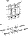
- FIG. 1 shows a schematic view of a section of a three-rail track 2.
- This three-rail track 2 comprises two outer rails 4, 6 for the realization of the standard gauge and an inner floor rail 8, which is used together with the outer floor rail 4 for the realization of the meter gauge.
- a Eurobalise 10 is additionally arranged longitudinally, which, when crossing a rail vehicle equipped with ETCS equipment, transmits data unidirectionally from the Eurobalise 10 to the rail vehicle or also exchanges it bidirectionally.
- two transverse struts 12 are provided, which are fastened to the rail feet of the two outer rails 4, 6.
- a mounting plate 14 is fixed by screwing, on which then the Eurobalise 10 is mounted.
- FIG. 2 shows a schematic representation of a view of the cross braces 12 and the mounting plate 14 with built Eurobalise 10 as shown in FIG. 1 for the situation in the three-rail track 2 is shown.
- the mounting plate 14 has an H-shape (see FIG. 7 ), of which only the two vertical legs 14a, 14b of the H can be seen here.
- the horizontal leg 14c is here covered by the Eurobalise 10, which is mounted on this.
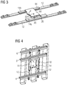
- FIGS. 4 to 6 now show towards the FIGS. 1 to 3 a changed only to the effect that the Eurobalise 10 is arranged only transverse to the three-rail track 2.
- FIGS. 4 and 6 As a result, a small part of the horizontal leg 14c can now also be seen, since in this installation position it is no longer completely covered by the Eurobalise 10.
- FIG. 7 shows in detail the mounting plate 14, which may be made of a GRP material, for example.
- the threaded bushing pair 26 serves to mount the Eurobalise 10 across the track; Accordingly, the threaded bushing pair 28 is used for mounting along the track.
- the length of the legs 14a and 14b is dimensioned so that hereby a metal-free to be left room around the Eurobalise 10 around can be defined.
Landscapes
- Engineering & Computer Science (AREA)
- Mechanical Engineering (AREA)
- Train Traffic Observation, Control, And Security (AREA)
Abstract
Description
- Die vorliegende Erfindung bezieht sich auf ein System zur longitudinalen und transversalen Befestigung einer Balise in einem Dreischienengleis.
- Für Normalspur- und Vierschienengleise sowie Normalspurgleise mit Führungsschienen haben die Schweizerischen Bundesbahnen Anfang 2017 Langsamfahrstellen mittels Euro-Balisen eingeführt. Euro-Balisen oder auch einfach Balisen genannt sind nach dem ETCS-Standard (European Train Control System) betriebene gleisseitig angeordnete Transponder für einen Datenaustausch mit einem die Balise überfahrenden Schienenfahrzeug mit entsprechender ETCS-konformer Fahrzeugausrüstung, wie z.B. ETCS-Antenne, Telepowering-System, Fahrzeugrechner (Onboard Unit OBU). Die Balise, die im wesentlichen quaderförmig ist und daher in der Aufsicht eine im wesentlichen rechteckige Form aufweist, wird dabei auf Querträgern, die senkrecht zum Verlauf der Schienen angeordnet sind, ebenfals quer zum Gleis angegeordnet (transversal).
- In der Schweiz sind aber beispielsweise etwa 20 km des Normalspurnetzes mit einem Dreischienengleis für Normal- und Meterspur ausgestattet. Beispielhaft können hierfür die Strecken Chur-Domat/Ems, Niederbipp-Oberbipp, Luzern-Kriens-Mattenhof, Zollikofen-Worblaufen-Deisswil sowie diverse Industriegleise genannt werden. Bei diesem Dreischienengleis ist es nicht möglich, die Balise transversal zu montieren. Einerseits ist der Schienenfuss des mittleren Gleises im Weg und andererseits wird der zum ordnungsgemässen Funkbetrieb der Balise gemäss ETCS-Standard geforderte metallfreie Raum deutlich verletzt.
- Damit die Euro-Balise in einem Dreischienengleis eingesetzt werden kann, muss sie daher längs zum Gleis und etwa 40 mm aus der Mitte heraus versetzt montiert werden (longitudinale Anordnung). Dabei wird der geforderte metallfreie Raum trotz der Versetzung aus der Mitte heraus immer noch leicht verletzt, aber Versuche und Einsätze im Feld haben gezeigt, dass die Längsmontage der Balise ihre Funktionstüchtigkeit nicht beeinträchtigt.
- Im Normalbetrieb werden daher heutzutage longitudinal verlegte Euro-Balisen an einem Signalstandort (nahe Signal) folgendermassen montiert:
Bei Holz- und Betonschwellen werden die Balisenbestigungslöcher in die Schwelle gebohrt, während bei Metallschwellen eine spezielle Montageplatte auf die Schwelle geschweisst wird. Dabei sind folglich Bohr- und Schweissarbeiten zu verrichten, was sehr zeitaufwändig und teuer ist. - Bei Langsamfahrstellen, z.B. infolge Baustellenbetriebs, muss die Euro-Balise einfach, schnell, sicher und überall auf der Strecke montierbar/demontierbar sein und darf nach ihrer Entfernung, beispielsweise nach Abschluss der Bauarbeiten, keine Montagespuren hinterlassen, also explizit keine Bohrlöcher in oder Schweissnähte auf den Schwellen. Bei Langsamfahrstellen ist es zudem usus, Ersatzschienen im Gleis abzulegen. Liegen diese Ersatzschienen zu nahe an der Eurobalise, kann die Übertragung der Balisentelegramme zum Fahrzeug aufgrund der eingebrachten Suszeptibilitäten (elektrisch wie magnetisch) beeinträchtigt werden. Daher ist es erforderlich, die Gleisarbeiter immer wieder auf diesen Umstand hinzuweisen, was mal mit mehr und mal mit weniger Erfolg gelingt.
- Am Übergang von Dreischienengleisen zur Normalspur kann es zudem vorkommen, dass die Eurobalisen einmal längs und am anderen Ende einmal quer montiert werden müssen. Auch hierfür gibt es momentan noch keine einfach einsetzbare Lösung.
- Der vorliegenden Erfindung liegt daher die Aufgabe zugrunde, ein System zur Befestigung einer Balise in einem Dreischienengleis anzugeben, das in der Montage einfach ist, rückwirkungsfrei demontierbar ist und zugleich die Montage der Balise längs und quer zum Gleis ermöglicht und dabei hilft den metallfrei zu haltenden Raum um die Balise herum anzuzeigen.
- Diese Aufgabe wird erfindungsgemäss durch ein System zur Befestigung einer Balise in einem Dreischiengleis gelöst, umfassend:
- a) zwei in einem Abstand voneinander angeordnete Querstreben, die jeweils an den Schienenfüssen der äusseren Schienen befestigt sind;
- b) eine Montageplatte für die Balise, die an den beiden Querstreben befestigt ist und Aufnahmepunkte für die Befestigung der Balisen aufweist; und
- c) eine auf der Montageplatte angeordnete in Aufsicht im wesentlichen rechteckige Balise, wobei die Balise aufgrund der vorhandenen Aufnahmepunkte quer oder längs zum Verlauf der Stockschienen ausgerichtet montierbar ist.
- Auf diese Weise wird ein System bereitgestellt, dass sich durch die Montage an den Schienenfüssen leicht befestigen und wieder lösen lässt. Die Montageplatte erleichert ebenfalls die korrekte Montage und Demontage der Balise in der gewünschten Ausrichtung, weil die Aufnahmepunkte so angeordnet sind, dass die Balise quer oder längs zum Gleis befestigt werden kann.
- Eine besonders vorteilhafte Ausgestaltung der Erfindung ergibt sich, wenn die Montageplatte in Form des Grossbuchstabens H ausgestaltet ist, wobei die beiden senkrechten Schenkel des H in Richtung des Verlaufs der Querstreben anordenbar sind. Somit wird der waagrecht verlaufende Verbindungssteg des H für die Montageplatte zur Aufnahme der Balise "reserviert". Die Befestigung der Montageplatte an den Querstreben kann so ausserhalb dieses Bereichs erfolgen.
- In einer vorteilhaften Weiterbildung der Erfindung kann die Länge der beiden Schenkel des H einen Raum um die Balise herum definieren, der zur Gewährleistung einer ordnungsgemässen Funktion der Balise metallfrei zu bleiben hat. Auf diese Weise ist beispielsweise für Gleisarbeiter intuitiv erkennbar, dass im Gleis abgelegte Ersatzschienen die beiden Schenkel der Montageplatte nicht bedecken dürfen.
- Weitere vorteilhafte Ausgestaltungen der vorliegenden Erfindung sind den übrigen Unteransprüchen zu entnehmen.
- Vorteilhafte Ausführungsbeispiele der vorliegenden Erfindung werden nachfolgend mit Bezug auf die anhängenden Zeichnung näher erläutert. Dabei zeigen:
- Figur 1
- in schematischer Darstellung einen Ausschnitt aus einem Dreischienengleis mit längs montierter Eurobalise;
- Figur 2
- in schematischer Darstellung eine Ansicht von Querstreben und Montageplatte mit verbauter Eurobalise wie in
Figur 1 im Gleis verbaut; - Figur 3
- die Ansicht von
Figur 2 mit zusätzlich montiertem Abschirmblech für die Eurobalise; - Figur 4
- in schematischer Darstellung einen Ausschnitt aus einem Dreischienengleis mit quer montierter Eurobalise;
- Figur 5
- in schematischer Darstellung eine Ansicht von Querstreben und Montageplatte mit verbauter Eurobalise wie in
Figur 4 im Gleis verbaut; - Figur 6
- die Ansicht von
Figur 5 mit zusätzlich montiertem Abschirmblech für die Eurobalise; und - Figur 7
- in schematischer Ansicht die Montageplatte, wie sie in den
Figuren 1 bis 6 zur Befestigung der Eurobalise eingesetzt worden ist. -
Figur 1 zeigt in schematischer Ansicht einen Ausschnitt aus einem Dreischienengleis 2. Dieses Dreischienengleis 2 umfasst zwei äussere Schienen 4, 6 zur Realisierung der Normalspur sowie eine innere Stockschiene 8, die zusammen mit der äusseren Stockschiene 4 zur Realisierung der Meterspur genutzt wird. Im Dreischienengleis 2 ist zudem eine Eurobalise 10 längsangeordnet, die bei Überfahrt eines Schienenfahrzeugs, welches mit ETCS-Equipment ausgerüstet ist, Daten unidirektional von der Eurobalise 10 zum Schienenfahrzeug funkt oder auch bidirektional austauscht. Zur Anordnung der Eurobalise 10 sind zwei Querstreben 12 vorgesehen, die an den Schienenfüssen der beiden äusseren Schienen 4, 6 befestigt sind. Auf den Querstreben 12 ist eine Montageplatte 14 durch Verschrauben befestigt, auf der dann die Eurobalise 10 montiert ist. -
Figur 2 zeigt in schematischer Darstellung eine Ansicht der Querstreben 12 und der Montageplatte 14 mit verbauter Eurobalise 10 wie dies inFigur 1 für die Situation im Dreischienengleis 2 dargestellt ist. Gut erkennbar sind Befestigungsmittel 16, mit denen die Querstreben 12 im Unterflureinbau an den Schienenfüssen fixiert werden, ohne dass Löcher in die Schienenfüsse gebohrt werden müssen. Die Montageplatte 14 weist eine H-Form auf (sieheFigur 7 ), von der hier nur die beiden senkrechten Schenkel 14a, 14b des H zu sehen sind. Der waagrechte Schenkel 14c ist hier von der Eurobalise 10 verdeckt, die auf diesem montiert ist. DieFigur 3 zeigt exakt dieselbe Situation mit der einzigen Änderung, dass hier noch ein Abdeckblech 18 auf der Eurobalise 10 befestigt ist, um die Eurobalise 10 aus dem Betrieb zu nehmen (Funkdaten werden abgeschirmt und erreichen daher die Fahrzeugantenne nicht). Gut erkennbar sind auch Schrauben 20 und 22, mit denen die Montageplatte 14 auf den Querstreben 12 und die Eurobalise 10 auf der Montageplatte befestigt werden. - Die
Figuren 4 bis 6 zeigen nun gegenüber denFiguren 1 bis 3 eine nur dahingehend geänderte Situation, dass die Eurobalise 10 nur quer zum Dreischienengleis 2 angeordnet ist. In denFiguren 4 und6 ist folglich nun auch ein kleiner Teil des waagrechten Schenkels 14c erkennbar, da dieser bei dieser Einbaulage nun nicht mehr ganz von der Eurobalise 10 überdeckt ist. - Die
Figur 7 zeigt im Detail die Montageplatte 14, die beispielsweise aus einem GFK-Material hergestellt sein kann. Schön erkennbar sind hier Bohrungen 24 für die Befestigung an den Querstreben sowie Gewindebuchsenpaare 26, 28. Das Gewindebuchsenpaar 26 dient dabei zur Montage der Eurobalise 10 quer zum Gleis; entsprechend dient das Gewindebuchsenpaar 28 zur Montage längs zum Gleis. Die Länge der Schenkel 14a und 14b ist dabei so bemessen, dass hiermit ein metallfrei zu bleibender Raum um die Eurobalise 10 herum definiert werden kann.
Claims (3)
- System zur Befestigung einer Balise (10) in einem Dreischienengleis, respektive Gleis (2) zwischen zwei äusseren Schienen (4, 6), umfassend:a) zwei in einem Abstand voneinander angeordnete Querstreben (12), die jeweils an den Schienenfüssen der äusseren Schienen (4, 6) befestigt sind;b) eine Montageplatte (14) für die Balise (10), die an den Querstreben (12) befestigt ist und Aufnahmepunkte (26, 28) für die Befestigung der Balise (10) aufweist; undc) eine auf der Montageplatte (10) angeordnete in Aufsicht im wesentlichen rechteckige Balise (10), wobei die Balise (10) aufgrund der vorhandenen Aufnahmepunkte (26, 28) quer oder längs zum Verlauf der Stockschienen (4, 6) ausgerichtet montierbar ist.
- System nach Anspruch 1,
dadurch gekennzeichnet, dass
die Montageplatte (14) in Form des Grossbuchstaben H ausgestaltet ist, wobei die beiden senkrechten Schenkel (14a, 14b) des H in Richtung des Verlaufs der Querstreben (12) anordenbar sind. - System nach Anspruch 1 oder 2,
dadurch gekennzeichnet, dass
die Länge der beiden senkrechten Schenkel (14a, 14b) des H einen Raum um die Balise (10) herum definieren, der zur Gewährleistung einer ordnungsgemässen Funktion der Balise (10) metallfrei zu bleiben hat.
Priority Applications (1)
| Application Number | Priority Date | Filing Date | Title |
|---|---|---|---|
| EP18162161.6A EP3539842B1 (de) | 2018-03-16 | 2018-03-16 | System zur longitudinalen und transversalen befestigung einer balise in einem dreischienengleis |
Applications Claiming Priority (1)
| Application Number | Priority Date | Filing Date | Title |
|---|---|---|---|
| EP18162161.6A EP3539842B1 (de) | 2018-03-16 | 2018-03-16 | System zur longitudinalen und transversalen befestigung einer balise in einem dreischienengleis |
Publications (3)
| Publication Number | Publication Date |
|---|---|
| EP3539842A1 true EP3539842A1 (de) | 2019-09-18 |
| EP3539842C0 EP3539842C0 (de) | 2024-08-28 |
| EP3539842B1 EP3539842B1 (de) | 2024-08-28 |
Family
ID=61800272
Family Applications (1)
| Application Number | Title | Priority Date | Filing Date |
|---|---|---|---|
| EP18162161.6A Active EP3539842B1 (de) | 2018-03-16 | 2018-03-16 | System zur longitudinalen und transversalen befestigung einer balise in einem dreischienengleis |
Country Status (1)
| Country | Link |
|---|---|
| EP (1) | EP3539842B1 (de) |
Citations (4)
| Publication number | Priority date | Publication date | Assignee | Title |
|---|---|---|---|---|
| JP2002331935A (ja) * | 2001-05-10 | 2002-11-19 | East Japan Railway Co | 地上子取付金具 |
| JP2008001259A (ja) * | 2006-06-23 | 2008-01-10 | West Japan Railway Co | 可搬型ats地上子 |
| KR20130093315A (ko) * | 2012-02-14 | 2013-08-22 | (주) 주은산업 | 열차신호제어용 발리스 고정장치 |
| KR20140072317A (ko) * | 2012-11-30 | 2014-06-13 | 한국철도공사 | 원터치식 발리스 취부대 |
-
2018
- 2018-03-16 EP EP18162161.6A patent/EP3539842B1/de active Active
Patent Citations (4)
| Publication number | Priority date | Publication date | Assignee | Title |
|---|---|---|---|---|
| JP2002331935A (ja) * | 2001-05-10 | 2002-11-19 | East Japan Railway Co | 地上子取付金具 |
| JP2008001259A (ja) * | 2006-06-23 | 2008-01-10 | West Japan Railway Co | 可搬型ats地上子 |
| KR20130093315A (ko) * | 2012-02-14 | 2013-08-22 | (주) 주은산업 | 열차신호제어용 발리스 고정장치 |
| KR20140072317A (ko) * | 2012-11-30 | 2014-06-13 | 한국철도공사 | 원터치식 발리스 취부대 |
Also Published As
| Publication number | Publication date |
|---|---|
| EP3539842C0 (de) | 2024-08-28 |
| EP3539842B1 (de) | 2024-08-28 |
Similar Documents
| Publication | Publication Date | Title |
|---|---|---|
| DE3928277C1 (de) | ||
| DE19841936C2 (de) | Fahrweg für Hochbahnen | |
| EP1121573B1 (de) | Gleiswaage | |
| DE60312357T2 (de) | Erhöhter Umleitungsabschnitt für ein Eisenbahngleis | |
| WO2008138761A1 (de) | Vorrichtung und verfahren zur zugbeeinflussung an einem bahnübergang | |
| EP3539842B1 (de) | System zur longitudinalen und transversalen befestigung einer balise in einem dreischienengleis | |
| DE202007004297U1 (de) | Schienenfußklammer-Set mit schwingungsdämpfenden Stabilisatoren zum Befestigen von Impulsgebern | |
| DE20308265U1 (de) | Fahrweg für Magnetschwebefahrzeuge | |
| EP3369861B1 (de) | Vorrichtung zur anordnung einer zugsicherungskomponente in einem gleisbereich | |
| DE19817597C1 (de) | Schienenbefestigung an einer Schwelle für unterschiedliche Spursysteme | |
| DE102017122770A1 (de) | Eindeckung für Bahngeleise | |
| DE102012216620A1 (de) | Verfahren und Vorrichtung zum Einrichten, Aktualisieren und Überwachen besonderer Gleisabschnitte | |
| DE202010008526U1 (de) | Betonschwelle | |
| DE10124842B4 (de) | Stählerne Eisenbahnbrücke sowie Aufnahmesystem für Schienen | |
| DE19962519C1 (de) | Halterung für einen Verschlusskasten | |
| DE19924967C1 (de) | Verfahren zum Auflösen gestörter Bahnhofseinfahrten auf Strecken mit Zentralblock | |
| DE10107116A1 (de) | Ausrichteinrichtung und Verfahren zum Ausrichten und Einstellen der Soll-Einbaulage eines vormontierten Gleisrostes in ein schotterloses Oberbausystem in Trogbauweise | |
| EP0856608A1 (de) | Modulare Hohlschwelle für ein Weichenstellsystem | |
| EP1346899A1 (de) | Weichenstellsystem | |
| AT337426B (de) | Anordnung zum verbinden von plattenelementen | |
| DE4416437C1 (de) | Schienenbefestigung | |
| DE2854769A1 (de) | Einschienenhaengebahnaufhaengung fuer den berg- und tunnelbau | |
| DE626118C (de) | Verfahren zur Auswechselung eines Eisenbahnoberbaues, insbesondere zwecks Einbaues von staerkeren Schienen | |
| DE102015009205A1 (de) | Schwelle zur Messung von Radaufstandskräften | |
| DE202005005550U1 (de) | Freitragende und montagefähige Signalhalterung für Gleisanlagen |
Legal Events
| Date | Code | Title | Description |
|---|---|---|---|
| PUAI | Public reference made under article 153(3) epc to a published international application that has entered the european phase |
Free format text: ORIGINAL CODE: 0009012 |
|
| STAA | Information on the status of an ep patent application or granted ep patent |
Free format text: STATUS: THE APPLICATION HAS BEEN PUBLISHED |
|
| AK | Designated contracting states |
Kind code of ref document: A1 Designated state(s): AL AT BE BG CH CY CZ DE DK EE ES FI FR GB GR HR HU IE IS IT LI LT LU LV MC MK MT NL NO PL PT RO RS SE SI SK SM TR |
|
| AX | Request for extension of the european patent |
Extension state: BA ME |
|
| STAA | Information on the status of an ep patent application or granted ep patent |
Free format text: STATUS: REQUEST FOR EXAMINATION WAS MADE |
|
| 17P | Request for examination filed |
Effective date: 20200305 |
|
| RBV | Designated contracting states (corrected) |
Designated state(s): AL AT BE BG CH CY CZ DE DK EE ES FI FR GB GR HR HU IE IS IT LI LT LU LV MC MK MT NL NO PL PT RO RS SE SI SK SM TR |
|
| RAP1 | Party data changed (applicant data changed or rights of an application transferred) |
Owner name: SIEMENS MOBILITY AG |
|
| STAA | Information on the status of an ep patent application or granted ep patent |
Free format text: STATUS: EXAMINATION IS IN PROGRESS |
|
| 17Q | First examination report despatched |
Effective date: 20210922 |
|
| GRAP | Despatch of communication of intention to grant a patent |
Free format text: ORIGINAL CODE: EPIDOSNIGR1 |
|
| STAA | Information on the status of an ep patent application or granted ep patent |
Free format text: STATUS: GRANT OF PATENT IS INTENDED |
|
| INTG | Intention to grant announced |
Effective date: 20240513 |
|
| GRAS | Grant fee paid |
Free format text: ORIGINAL CODE: EPIDOSNIGR3 |
|
| GRAA | (expected) grant |
Free format text: ORIGINAL CODE: 0009210 |
|
| STAA | Information on the status of an ep patent application or granted ep patent |
Free format text: STATUS: THE PATENT HAS BEEN GRANTED |
|
| AK | Designated contracting states |
Kind code of ref document: B1 Designated state(s): AL AT BE BG CH CY CZ DE DK EE ES FI FR GB GR HR HU IE IS IT LI LT LU LV MC MK MT NL NO PL PT RO RS SE SI SK SM TR |
|
| REG | Reference to a national code |
Ref country code: GB Ref legal event code: FG4D Free format text: NOT ENGLISH |
|
| REG | Reference to a national code |
Ref country code: CH Ref legal event code: EP |
|
| REG | Reference to a national code |
Ref country code: DE Ref legal event code: R096 Ref document number: 502018015050 Country of ref document: DE |
|
| REG | Reference to a national code |
Ref country code: IE Ref legal event code: FG4D Free format text: LANGUAGE OF EP DOCUMENT: GERMAN |
|
| U01 | Request for unitary effect filed |
Effective date: 20240828 |
|
| U07 | Unitary effect registered |
Designated state(s): AT BE BG DE DK EE FI FR IT LT LU LV MT NL PT RO SE SI Effective date: 20240903 |
|
| PG25 | Lapsed in a contracting state [announced via postgrant information from national office to epo] |
Ref country code: NO Free format text: LAPSE BECAUSE OF FAILURE TO SUBMIT A TRANSLATION OF THE DESCRIPTION OR TO PAY THE FEE WITHIN THE PRESCRIBED TIME-LIMIT Effective date: 20241128 |
|
| PG25 | Lapsed in a contracting state [announced via postgrant information from national office to epo] |
Ref country code: GR Free format text: LAPSE BECAUSE OF FAILURE TO SUBMIT A TRANSLATION OF THE DESCRIPTION OR TO PAY THE FEE WITHIN THE PRESCRIBED TIME-LIMIT Effective date: 20241129 Ref country code: PL Free format text: LAPSE BECAUSE OF FAILURE TO SUBMIT A TRANSLATION OF THE DESCRIPTION OR TO PAY THE FEE WITHIN THE PRESCRIBED TIME-LIMIT Effective date: 20240828 |
|
| PG25 | Lapsed in a contracting state [announced via postgrant information from national office to epo] |
Ref country code: IS Free format text: LAPSE BECAUSE OF FAILURE TO SUBMIT A TRANSLATION OF THE DESCRIPTION OR TO PAY THE FEE WITHIN THE PRESCRIBED TIME-LIMIT Effective date: 20241228 |
|
| PG25 | Lapsed in a contracting state [announced via postgrant information from national office to epo] |
Ref country code: HR Free format text: LAPSE BECAUSE OF FAILURE TO SUBMIT A TRANSLATION OF THE DESCRIPTION OR TO PAY THE FEE WITHIN THE PRESCRIBED TIME-LIMIT Effective date: 20240828 |
|
| PG25 | Lapsed in a contracting state [announced via postgrant information from national office to epo] |
Ref country code: RS Free format text: LAPSE BECAUSE OF FAILURE TO SUBMIT A TRANSLATION OF THE DESCRIPTION OR TO PAY THE FEE WITHIN THE PRESCRIBED TIME-LIMIT Effective date: 20241128 Ref country code: ES Free format text: LAPSE BECAUSE OF FAILURE TO SUBMIT A TRANSLATION OF THE DESCRIPTION OR TO PAY THE FEE WITHIN THE PRESCRIBED TIME-LIMIT Effective date: 20240828 |
|
| PG25 | Lapsed in a contracting state [announced via postgrant information from national office to epo] |
Ref country code: RS Free format text: LAPSE BECAUSE OF FAILURE TO SUBMIT A TRANSLATION OF THE DESCRIPTION OR TO PAY THE FEE WITHIN THE PRESCRIBED TIME-LIMIT Effective date: 20241128 Ref country code: PL Free format text: LAPSE BECAUSE OF FAILURE TO SUBMIT A TRANSLATION OF THE DESCRIPTION OR TO PAY THE FEE WITHIN THE PRESCRIBED TIME-LIMIT Effective date: 20240828 Ref country code: NO Free format text: LAPSE BECAUSE OF FAILURE TO SUBMIT A TRANSLATION OF THE DESCRIPTION OR TO PAY THE FEE WITHIN THE PRESCRIBED TIME-LIMIT Effective date: 20241128 Ref country code: IS Free format text: LAPSE BECAUSE OF FAILURE TO SUBMIT A TRANSLATION OF THE DESCRIPTION OR TO PAY THE FEE WITHIN THE PRESCRIBED TIME-LIMIT Effective date: 20241228 Ref country code: HR Free format text: LAPSE BECAUSE OF FAILURE TO SUBMIT A TRANSLATION OF THE DESCRIPTION OR TO PAY THE FEE WITHIN THE PRESCRIBED TIME-LIMIT Effective date: 20240828 Ref country code: GR Free format text: LAPSE BECAUSE OF FAILURE TO SUBMIT A TRANSLATION OF THE DESCRIPTION OR TO PAY THE FEE WITHIN THE PRESCRIBED TIME-LIMIT Effective date: 20241129 Ref country code: ES Free format text: LAPSE BECAUSE OF FAILURE TO SUBMIT A TRANSLATION OF THE DESCRIPTION OR TO PAY THE FEE WITHIN THE PRESCRIBED TIME-LIMIT Effective date: 20240828 |
|
| PG25 | Lapsed in a contracting state [announced via postgrant information from national office to epo] |
Ref country code: SM Free format text: LAPSE BECAUSE OF FAILURE TO SUBMIT A TRANSLATION OF THE DESCRIPTION OR TO PAY THE FEE WITHIN THE PRESCRIBED TIME-LIMIT Effective date: 20240828 |
|
| U20 | Renewal fee for the european patent with unitary effect paid |
Year of fee payment: 8 Effective date: 20250320 |
|
| PG25 | Lapsed in a contracting state [announced via postgrant information from national office to epo] |
Ref country code: CZ Free format text: LAPSE BECAUSE OF FAILURE TO SUBMIT A TRANSLATION OF THE DESCRIPTION OR TO PAY THE FEE WITHIN THE PRESCRIBED TIME-LIMIT Effective date: 20240828 |
|
| PG25 | Lapsed in a contracting state [announced via postgrant information from national office to epo] |
Ref country code: SK Free format text: LAPSE BECAUSE OF FAILURE TO SUBMIT A TRANSLATION OF THE DESCRIPTION OR TO PAY THE FEE WITHIN THE PRESCRIBED TIME-LIMIT Effective date: 20240828 |
|
| PLBE | No opposition filed within time limit |
Free format text: ORIGINAL CODE: 0009261 |
|
| STAA | Information on the status of an ep patent application or granted ep patent |
Free format text: STATUS: NO OPPOSITION FILED WITHIN TIME LIMIT |
|
| PGFP | Annual fee paid to national office [announced via postgrant information from national office to epo] |
Ref country code: CH Payment date: 20250611 Year of fee payment: 8 |
|
| 26N | No opposition filed |
Effective date: 20250530 |
|
| PG25 | Lapsed in a contracting state [announced via postgrant information from national office to epo] |
Ref country code: MC Free format text: LAPSE BECAUSE OF FAILURE TO SUBMIT A TRANSLATION OF THE DESCRIPTION OR TO PAY THE FEE WITHIN THE PRESCRIBED TIME-LIMIT Effective date: 20240828 |
|
| GBPC | Gb: european patent ceased through non-payment of renewal fee |
Effective date: 20250316 |
|
| PG25 | Lapsed in a contracting state [announced via postgrant information from national office to epo] |
Ref country code: GB Free format text: LAPSE BECAUSE OF NON-PAYMENT OF DUE FEES Effective date: 20250316 |
|
| PG25 | Lapsed in a contracting state [announced via postgrant information from national office to epo] |
Ref country code: IE Free format text: LAPSE BECAUSE OF NON-PAYMENT OF DUE FEES Effective date: 20250316 |
|
| U20 | Renewal fee for the european patent with unitary effect paid |
Year of fee payment: 9 Effective date: 20260320 |