EP3539675A1 - Dispositif d'application d'un produit fluide dont le débit de dosage dépend de la vitesse d'un orifice de sortie dudit produit fluide - Google Patents
Dispositif d'application d'un produit fluide dont le débit de dosage dépend de la vitesse d'un orifice de sortie dudit produit fluide Download PDFInfo
- Publication number
- EP3539675A1 EP3539675A1 EP19162989.8A EP19162989A EP3539675A1 EP 3539675 A1 EP3539675 A1 EP 3539675A1 EP 19162989 A EP19162989 A EP 19162989A EP 3539675 A1 EP3539675 A1 EP 3539675A1
- Authority
- EP
- European Patent Office
- Prior art keywords
- applicator
- fluid product
- speed
- outlet orifice
- measuring device
- Prior art date
- Legal status (The legal status is an assumption and is not a legal conclusion. Google has not performed a legal analysis and makes no representation as to the accuracy of the status listed.)
- Granted
Links
Images


Classifications
-
- B—PERFORMING OPERATIONS; TRANSPORTING
- B05—SPRAYING OR ATOMISING IN GENERAL; APPLYING FLUENT MATERIALS TO SURFACES, IN GENERAL
- B05B—SPRAYING APPARATUS; ATOMISING APPARATUS; NOZZLES
- B05B12/00—Arrangements for controlling delivery; Arrangements for controlling the spray area
- B05B12/08—Arrangements for controlling delivery; Arrangements for controlling the spray area responsive to condition of liquid or other fluent material to be discharged, of ambient medium or of target ; responsive to condition of spray devices or of supply means, e.g. pipes, pumps or their drive means
- B05B12/085—Arrangements for controlling delivery; Arrangements for controlling the spray area responsive to condition of liquid or other fluent material to be discharged, of ambient medium or of target ; responsive to condition of spray devices or of supply means, e.g. pipes, pumps or their drive means responsive to flow or pressure of liquid or other fluent material to be discharged
-
- B—PERFORMING OPERATIONS; TRANSPORTING
- B05—SPRAYING OR ATOMISING IN GENERAL; APPLYING FLUENT MATERIALS TO SURFACES, IN GENERAL
- B05B—SPRAYING APPARATUS; ATOMISING APPARATUS; NOZZLES
- B05B12/00—Arrangements for controlling delivery; Arrangements for controlling the spray area
- B05B12/08—Arrangements for controlling delivery; Arrangements for controlling the spray area responsive to condition of liquid or other fluent material to be discharged, of ambient medium or of target ; responsive to condition of spray devices or of supply means, e.g. pipes, pumps or their drive means
- B05B12/12—Arrangements for controlling delivery; Arrangements for controlling the spray area responsive to condition of liquid or other fluent material to be discharged, of ambient medium or of target ; responsive to condition of spray devices or of supply means, e.g. pipes, pumps or their drive means responsive to conditions of ambient medium or target, e.g. humidity, temperature position or movement of the target relative to the spray apparatus
- B05B12/126—Arrangements for controlling delivery; Arrangements for controlling the spray area responsive to condition of liquid or other fluent material to be discharged, of ambient medium or of target ; responsive to condition of spray devices or of supply means, e.g. pipes, pumps or their drive means responsive to conditions of ambient medium or target, e.g. humidity, temperature position or movement of the target relative to the spray apparatus responsive to target velocity, e.g. to relative velocity between spray apparatus and target
-
- B—PERFORMING OPERATIONS; TRANSPORTING
- B05—SPRAYING OR ATOMISING IN GENERAL; APPLYING FLUENT MATERIALS TO SURFACES, IN GENERAL
- B05C—APPARATUS FOR APPLYING FLUENT MATERIALS TO SURFACES, IN GENERAL
- B05C5/00—Apparatus in which liquid or other fluent material is projected, poured or allowed to flow on to the surface of the work
- B05C5/02—Apparatus in which liquid or other fluent material is projected, poured or allowed to flow on to the surface of the work the liquid or other fluent material being discharged through an outlet orifice by pressure, e.g. from an outlet device in contact or almost in contact, with the work
- B05C5/0208—Apparatus in which liquid or other fluent material is projected, poured or allowed to flow on to the surface of the work the liquid or other fluent material being discharged through an outlet orifice by pressure, e.g. from an outlet device in contact or almost in contact, with the work for applying liquid or other fluent material to separate articles
-
- B—PERFORMING OPERATIONS; TRANSPORTING
- B05—SPRAYING OR ATOMISING IN GENERAL; APPLYING FLUENT MATERIALS TO SURFACES, IN GENERAL
- B05B—SPRAYING APPARATUS; ATOMISING APPARATUS; NOZZLES
- B05B12/00—Arrangements for controlling delivery; Arrangements for controlling the spray area
- B05B12/02—Arrangements for controlling delivery; Arrangements for controlling the spray area for controlling time, or sequence, of delivery
-
- B—PERFORMING OPERATIONS; TRANSPORTING
- B05—SPRAYING OR ATOMISING IN GENERAL; APPLYING FLUENT MATERIALS TO SURFACES, IN GENERAL
- B05B—SPRAYING APPARATUS; ATOMISING APPARATUS; NOZZLES
- B05B13/00—Machines or plants for applying liquids or other fluent materials to surfaces of objects or other work by spraying, not covered by groups B05B1/00 - B05B11/00
- B05B13/02—Means for supporting work; Arrangement or mounting of spray heads; Adaptation or arrangement of means for feeding work
- B05B13/04—Means for supporting work; Arrangement or mounting of spray heads; Adaptation or arrangement of means for feeding work the spray heads being moved during spraying operation
- B05B13/0431—Means for supporting work; Arrangement or mounting of spray heads; Adaptation or arrangement of means for feeding work the spray heads being moved during spraying operation with spray heads moved by robots or articulated arms, e.g. for applying liquid or other fluent material to three-dimensional [3D] surfaces
-
- B—PERFORMING OPERATIONS; TRANSPORTING
- B05—SPRAYING OR ATOMISING IN GENERAL; APPLYING FLUENT MATERIALS TO SURFACES, IN GENERAL
- B05B—SPRAYING APPARATUS; ATOMISING APPARATUS; NOZZLES
- B05B13/00—Machines or plants for applying liquids or other fluent materials to surfaces of objects or other work by spraying, not covered by groups B05B1/00 - B05B11/00
- B05B13/02—Means for supporting work; Arrangement or mounting of spray heads; Adaptation or arrangement of means for feeding work
- B05B13/04—Means for supporting work; Arrangement or mounting of spray heads; Adaptation or arrangement of means for feeding work the spray heads being moved during spraying operation
- B05B13/0447—Installation or apparatus for applying liquid or other fluent material to conveyed separate articles
-
- B—PERFORMING OPERATIONS; TRANSPORTING
- B05—SPRAYING OR ATOMISING IN GENERAL; APPLYING FLUENT MATERIALS TO SURFACES, IN GENERAL
- B05B—SPRAYING APPARATUS; ATOMISING APPARATUS; NOZZLES
- B05B13/00—Machines or plants for applying liquids or other fluent materials to surfaces of objects or other work by spraying, not covered by groups B05B1/00 - B05B11/00
- B05B13/02—Means for supporting work; Arrangement or mounting of spray heads; Adaptation or arrangement of means for feeding work
- B05B13/04—Means for supporting work; Arrangement or mounting of spray heads; Adaptation or arrangement of means for feeding work the spray heads being moved during spraying operation
- B05B13/0447—Installation or apparatus for applying liquid or other fluent material to conveyed separate articles
- B05B13/0457—Installation or apparatus for applying liquid or other fluent material to conveyed separate articles specially designed for applying liquid or other fluent material to three-dimensional [3D] surfaces of the work, e.g. by using several moving spray heads
-
- B—PERFORMING OPERATIONS; TRANSPORTING
- B05—SPRAYING OR ATOMISING IN GENERAL; APPLYING FLUENT MATERIALS TO SURFACES, IN GENERAL
- B05C—APPARATUS FOR APPLYING FLUENT MATERIALS TO SURFACES, IN GENERAL
- B05C11/00—Component parts, details or accessories not specifically provided for in groups B05C1/00 - B05C9/00
- B05C11/10—Storage, supply or control of liquid or other fluent material; Recovery of excess liquid or other fluent material
-
- B—PERFORMING OPERATIONS; TRANSPORTING
- B05—SPRAYING OR ATOMISING IN GENERAL; APPLYING FLUENT MATERIALS TO SURFACES, IN GENERAL
- B05C—APPARATUS FOR APPLYING FLUENT MATERIALS TO SURFACES, IN GENERAL
- B05C11/00—Component parts, details or accessories not specifically provided for in groups B05C1/00 - B05C9/00
- B05C11/10—Storage, supply or control of liquid or other fluent material; Recovery of excess liquid or other fluent material
- B05C11/1002—Means for controlling supply, i.e. flow or pressure, of liquid or other fluent material to the applying apparatus, e.g. valves
-
- B—PERFORMING OPERATIONS; TRANSPORTING
- B05—SPRAYING OR ATOMISING IN GENERAL; APPLYING FLUENT MATERIALS TO SURFACES, IN GENERAL
- B05C—APPARATUS FOR APPLYING FLUENT MATERIALS TO SURFACES, IN GENERAL
- B05C11/00—Component parts, details or accessories not specifically provided for in groups B05C1/00 - B05C9/00
- B05C11/10—Storage, supply or control of liquid or other fluent material; Recovery of excess liquid or other fluent material
- B05C11/1002—Means for controlling supply, i.e. flow or pressure, of liquid or other fluent material to the applying apparatus, e.g. valves
- B05C11/1015—Means for controlling supply, i.e. flow or pressure, of liquid or other fluent material to the applying apparatus, e.g. valves responsive to a conditions of ambient medium or target, e.g. humidity, temperature ; responsive to position or movement of the coating head relative to the target
- B05C11/1023—Means for controlling supply, i.e. flow or pressure, of liquid or other fluent material to the applying apparatus, e.g. valves responsive to a conditions of ambient medium or target, e.g. humidity, temperature ; responsive to position or movement of the coating head relative to the target responsive to velocity of target, e.g. to web advancement rate
-
- B—PERFORMING OPERATIONS; TRANSPORTING
- B05—SPRAYING OR ATOMISING IN GENERAL; APPLYING FLUENT MATERIALS TO SURFACES, IN GENERAL
- B05C—APPARATUS FOR APPLYING FLUENT MATERIALS TO SURFACES, IN GENERAL
- B05C5/00—Apparatus in which liquid or other fluent material is projected, poured or allowed to flow on to the surface of the work
- B05C5/002—Apparatus in which liquid or other fluent material is projected, poured or allowed to flow on to the surface of the work the work consisting of separate articles
-
- B—PERFORMING OPERATIONS; TRANSPORTING
- B05—SPRAYING OR ATOMISING IN GENERAL; APPLYING FLUENT MATERIALS TO SURFACES, IN GENERAL
- B05C—APPARATUS FOR APPLYING FLUENT MATERIALS TO SURFACES, IN GENERAL
- B05C5/00—Apparatus in which liquid or other fluent material is projected, poured or allowed to flow on to the surface of the work
- B05C5/02—Apparatus in which liquid or other fluent material is projected, poured or allowed to flow on to the surface of the work the liquid or other fluent material being discharged through an outlet orifice by pressure, e.g. from an outlet device in contact or almost in contact, with the work
- B05C5/0208—Apparatus in which liquid or other fluent material is projected, poured or allowed to flow on to the surface of the work the liquid or other fluent material being discharged through an outlet orifice by pressure, e.g. from an outlet device in contact or almost in contact, with the work for applying liquid or other fluent material to separate articles
- B05C5/0212—Apparatus in which liquid or other fluent material is projected, poured or allowed to flow on to the surface of the work the liquid or other fluent material being discharged through an outlet orifice by pressure, e.g. from an outlet device in contact or almost in contact, with the work for applying liquid or other fluent material to separate articles only at particular parts of the articles
- B05C5/0216—Apparatus in which liquid or other fluent material is projected, poured or allowed to flow on to the surface of the work the liquid or other fluent material being discharged through an outlet orifice by pressure, e.g. from an outlet device in contact or almost in contact, with the work for applying liquid or other fluent material to separate articles only at particular parts of the articles by relative movement of article and outlet according to a predetermined path
-
- B—PERFORMING OPERATIONS; TRANSPORTING
- B25—HAND TOOLS; PORTABLE POWER-DRIVEN TOOLS; MANIPULATORS
- B25J—MANIPULATORS; CHAMBERS PROVIDED WITH MANIPULATION DEVICES
- B25J11/00—Manipulators not otherwise provided for
- B25J11/0075—Manipulators for painting or coating
-
- B—PERFORMING OPERATIONS; TRANSPORTING
- B25—HAND TOOLS; PORTABLE POWER-DRIVEN TOOLS; MANIPULATORS
- B25J—MANIPULATORS; CHAMBERS PROVIDED WITH MANIPULATION DEVICES
- B25J13/00—Controls for manipulators
- B25J13/08—Controls for manipulators by means of sensing devices, e.g. viewing or touching devices
- B25J13/088—Controls for manipulators by means of sensing devices, e.g. viewing or touching devices with position, velocity or acceleration sensors
-
- B—PERFORMING OPERATIONS; TRANSPORTING
- B25—HAND TOOLS; PORTABLE POWER-DRIVEN TOOLS; MANIPULATORS
- B25J—MANIPULATORS; CHAMBERS PROVIDED WITH MANIPULATION DEVICES
- B25J15/00—Gripping heads and other end effectors
- B25J15/0019—End effectors other than grippers
-
- B—PERFORMING OPERATIONS; TRANSPORTING
- B25—HAND TOOLS; PORTABLE POWER-DRIVEN TOOLS; MANIPULATORS
- B25J—MANIPULATORS; CHAMBERS PROVIDED WITH MANIPULATION DEVICES
- B25J19/00—Accessories fitted to manipulators, e.g. for monitoring, for viewing; Safety devices combined with or specially adapted for use in connection with manipulators
- B25J19/02—Sensing devices
-
- B—PERFORMING OPERATIONS; TRANSPORTING
- B25—HAND TOOLS; PORTABLE POWER-DRIVEN TOOLS; MANIPULATORS
- B25J—MANIPULATORS; CHAMBERS PROVIDED WITH MANIPULATION DEVICES
- B25J9/00—Program-controlled manipulators
- B25J9/0093—Program-controlled manipulators co-operating with conveyor means
-
- G—PHYSICS
- G01—MEASURING; TESTING
- G01D—MEASURING NOT SPECIALLY ADAPTED FOR A SPECIFIC VARIABLE; ARRANGEMENTS FOR MEASURING TWO OR MORE VARIABLES NOT COVERED IN A SINGLE OTHER SUBCLASS; TARIFF METERING APPARATUS; MEASURING OR TESTING NOT OTHERWISE PROVIDED FOR
- G01D21/00—Measuring or testing not otherwise provided for
- G01D21/02—Measuring two or more variables by means not covered by a single other subclass
-
- B—PERFORMING OPERATIONS; TRANSPORTING
- B05—SPRAYING OR ATOMISING IN GENERAL; APPLYING FLUENT MATERIALS TO SURFACES, IN GENERAL
- B05B—SPRAYING APPARATUS; ATOMISING APPARATUS; NOZZLES
- B05B13/00—Machines or plants for applying liquids or other fluent materials to surfaces of objects or other work by spraying, not covered by groups B05B1/00 - B05B11/00
- B05B13/02—Means for supporting work; Arrangement or mounting of spray heads; Adaptation or arrangement of means for feeding work
- B05B13/0221—Means for supporting work; Arrangement or mounting of spray heads; Adaptation or arrangement of means for feeding work characterised by the means for moving or conveying the objects or other work, e.g. conveyor belts
- B05B13/0271—Means for supporting work; Arrangement or mounting of spray heads; Adaptation or arrangement of means for feeding work characterised by the means for moving or conveying the objects or other work, e.g. conveyor belts the object or work standing still during the spraying operation
Definitions
- fluid product is meant here and hereinafter a product which has a viscosity of between 1 mPa.s and 2 kPa.s, this viscosity being for example measured using a Brookfield Plan Cone viscometer in normal conditions of temperature and pressure. This term thus encompasses the products in the liquid state, perfectly deformable and low viscosity, but also the products generally called “pasty", more viscous than liquids and having an intermediate state between the liquid state and the solid state .
- the invention also relates to an applicator robot comprising such an application device, and a method for applying a fluid product to a substrate by means of such an application device.
- Application devices of the aforementioned type are known. They are generally used to apply fluid surfaces such as glue beads or paint to surfaces, in particular when it is necessary to precisely control the flow rate of the fluid product at the outlet of the application device.
- these application devices are mounted on robotic articulated arms controlled by control bays so as to move the application members of these application devices relative to the surfaces to be covered.
- control bays are most often arranged next to said articulated arms, and each application device has its own control cabinet disposed next to the control bay of the articulated arm on which the application device is mounted.
- the objective sought with the use of this type of application device is to distribute the fluid in the most homogeneous manner possible on the surface to be coated.
- a complication occurs on the other hand when the tool tip speed varies, for example when the direction of displacement of the applicator member changes following the arrival of the applicator member at the end of the surface to be covered.
- the dosing rate must be modified in proportion to the tip tool speed so as to continue to locally apply a quantity of product; in particular, the metering flow must be decreased as the displacement of the outlet orifice slows and increases as the displacement of the outlet orifice accelerates.
- An object of the invention is thus to allow the homogeneous application of a fluid product on a surface to be covered, whatever the speed of displacement of the outlet orifice of the fluid product relative to said surface and whatever the device used to move said outlet port.
- the subject of the invention is an application device of the aforementioned type, in which the application device also comprises a speed measuring device. adapted to determine a measured speed of the outlet orifice relative to an inertial reference frame, and the control module is configured to determine the control setpoint as a function of said measured speed.
- the invention also relates to an applicator robot for applying a fluid product to a substrate, the robot comprising a frame, an articulated arm formed of a plurality of segments articulated to each other, a wrist mounted to a end of the articulated arm, and an application device as defined above, the applicator member is mounted at a distal end of the wrist.
- the installation 2 represented on the Figure 1 is intended for the application of a fluid product on substrates 4.
- the fluid product is typically constituted by a high viscosity product, that is to say whose viscosity is greater than 3000 mPa.s.
- high viscosity products are typically elastomeric or epoxy sealants or adhesives.
- the fluid product has a viscosity of between 3000 and 300000 Pa.s.
- the substrates 4 are constituted by preformed plates, typically by stamped sheet metal plates.
- the installation 2 comprises, in known manner, a system 6 for moving the substrates 4 and an applicator robot 8 for applying the fluid product to the substrates 4.
- the displacement system 6 is configured to move the substrates 4 inside the installation 2 by immobilizing each substrate 4 relative to the floor 10 of the installation 2, for a predetermined duration, in a field of action of the robot applicator 8.
- the displacement system 6 is constituted by a drive belt carrying the substrates 4.
- the applicator robot 8 comprises a multiaxis robot 12, a control rack 14 for controlling the robot 12, an application device 16 for applying the fluid product to the substrates 4, a control cabinet 18 for controlling the device 12, and a supply system 19 for supplying the application device 16 with the fluid product.
- the multiaxis robot 12 comprises, in known manner, a frame (not shown) fixed relative to the floor 10, an articulated arm 20 formed of a plurality of segments 22 articulated to each other, and a wrist 24 mounted at one end of the arm articulated 20.
- the wrist 24 includes a proximal end (not shown) by which it is connected to one of the segments 22 of the arm 20, and a distal end (not shown) opposite the proximal end.
- the multiaxis robot 12 also comprises a plurality of motors (not shown), mounted at the interface between the segments 22 of the arm 20 and with the wrist 24, to cause said segments 22 and said wrist 24 to rotate relative to one another. .
- Control bay 14 comprises electrical circuits (not shown) for determining a control setpoint of each motor of robot 12 and supplying this control setpoint to each motor concerned.
- the application device 16 comprises an applicator member 30 for shaping the fluid product for application to the substrate.
- the applicator member 30 comprises an outlet orifice 32 for the outlet of the fluid product from the application device 16, this outlet orifice 32 typically being constituted by a nozzle.
- the applicator device 16 also comprises a speed measuring device 34, an adjusting member 36 able to adjust a metering flow rate of the fluid product through the outlet orifice 32, and a control module 38 for determining a set point. controlling the flow rate of the adjusting member 36 and supplying said control setpoint to the adjusting member 36.
- Each accelerometer 40 and each gyroscope 42 is typically constituted by an inertial electromechanical microsystem.
- the accelerometers 40, the gyroscope 42 and the magnetometer 44 are typically integrated in a common electronic card (not shown).
- the entire speed measuring device 34 is at a distance from the outlet port 32 of less than 15 cm. Thus, the movements measured by the speed measuring device 34 are very close to the movements of the outlet orifice 32.
- the speed measuring device 34 is, as shown, mounted on the applicator member 30.
- the speed measuring device 34 is configured to transmit the measured speed to the control module 38.
- the control member 36 is able to define the metering flow of the fluid product through the outlet orifice 32, said metering flow being a function of the flow control setpoint supplied by the control module 38.
- the adjusting member 36 is typically constituted by a pump supplying the applicator member 30, the flow rate of the fluid product at the outlet of said pump constituting the dosing flow rate.
- the adjusting member 36 is constituted by a single or double-acting pump comprising a chamber and a piston (not shown), the speed of movement of the piston in the chamber determining the dosing flow.
- the adjusting member 36 is constituted by an axial piston pump whose rotational speed determines the dosing flow.
- the adjusting member 36 is at a distance from the outlet orifice 32 of less than 15 cm.
- the control module 38 is configured to determine the flow control setpoint as a function of the measured speed, and to adapt this setpoint so that the ratio between the flow rate of the fluid product and the measured speed of the outlet orifice 32 is substantially constant.
- control module 38 is adapted to receive from the measuring device 34 the measured speed, and to deduce from this measured speed the control command in flow.
- control module 38 is typically embodied in the form of programmable logic components and / or dedicated integrated circuits included in the application device 16.
- the entire control module 38 is at a distance from the speed measuring device 34 less than 5 cm and at a distance from the adjusting member 36 less than 10 cm.
- the exchanges of information between the control module 38 and each of the speed measuring device 34 and the adjustment member 36 are almost identical. instantaneous, which allows a very high reactivity of the adjusting member 36 following the variations in speed of the outlet orifice determined by the measuring device 34.
- the applicator member 30, the speed measuring device 34, the adjustment member 36 and the control module 38 are all integrated in the same casing 46 mounted on the wrist 24 of the articulated arm. 20.
- the application device 16 is not mounted on the wrist 24: for example, the adjusting member 36 is mounted on the segment 22 of the articulated arm 20 closest to the wrist 24 .
- the applicator member 30 is preferably always mounted at the distal end of the wrist 24.
- the supply system 19 comprises a tank 50 containing the fluid product, and a fluid transfer system 52 for transferring the fluid contained in the tank 50 to an inlet 54 ( Figure 2 ) of the adjusting member 36.
- the fluid transfer system 52 is adapted to supply the fluid product to the application device 16 at a pressure greater than 1.1 times the atmospheric pressure.
- the fluid transfer system 52 comprises an elevator group 56 for pumping the fluid product into the tank 50, and a pipe 58 fluidly connecting an outlet (not shown) of the elevator group 56 to the inlet 54 of the organ adjustment 36.
- a process 100 for applying the fluid product by means of the installation 2 will now be described, with reference to the Figure 3 .
- a first step 110 the facility 2 and the substrates 4 are provided.
- This step 110 is followed by an initialization step 120.
- This step 120 includes a first substep in which the elevator group 56 is activated. The latter then begins to pump the product into the tank 50 and to push it back into line 58.
- Step 120 also comprises a second substep, substantially simultaneous with the first substep, during which the measuring device 34 is activated. From this substep, the measuring device 34 continuously measures the speed of the outlet port 32.
- a substrate 4 is provided by the displacement system 6 in the scope of action of the applicator robot 8, and then immobilized in said perimeter of action.
- the control bay 14 then controls, during a step 140, the displacement of the articulated arm 20 so as to place the outlet orifice 32 of the application device 16 facing a surface to be coated on the substrate 4 at a distance suitable for applying the fluid product to said surface.
- the applicator robot 8 initiates the application of the fluid product on the substrate 4.
- step 150 the outlet orifice 32 is moved by the robot 12, relative to the floor 10, at a first speed, following the surface to be covered, and a setpoint is communicated by the control cabinet 18 to the application device 16 for the application of the fluid product.
- Step 150 comprises a first substep 152 in which the first speed is measured by the measuring device 34.
- control module 38 determines a first control setpoint of the adjustment member 36 according to said first speed and communicates this first control setpoint to the adjustment member 36 when a substep 156.
- This control setpoint is received by the adjustment member 36 during a substep 158, after which the adjustment member 36 adjusts the dosing flow rate at a first rate during a substep 159.
- This first rate is such that the ratio of said first rate to the first rate is equal to a predetermined constant.
- the fluid product is then applied with a metering flow equal to the first flow rate throughout the rest of step 150.
- the robot 12 modifies the speed of displacement of the outlet orifice 32 relative to the floor 10. This change of speed typically consists of a slowdown occurring during a change in the direction of movement of the the outlet port 32.
- Step 160 is thus followed by a step 170 of continuing the application of the fluid product on the substrate 4 at a modified speed.
- the outlet orifice 32 is moved by the robot 12, relative to the floor 10, at the modified speed, following the surface to be covered, and a setpoint is communicated by the control cabinet 18 to the application device 16 for the application of the fluid product.
- Step 170 comprises a first substep 172 in which the modified speed is measured by the measuring device 34.
- control module 38 determines a new control setpoint of the adjustment member 36 according to said modified speed and communicates this new command setpoint to the adjustment member 36 when a sub-step 176.
- This new control setpoint is received by the adjusting member 36 during a sub-step 178, after which the adjusting member 36 adjusts, during a sub-step 179, the dosing flow to a new debit.
- This new flow rate is such that the ratio of said new flow rate to the modified speed is equal to said predetermined constant.
- the fluid product is then applied with a dosing rate equal to the new flow rate throughout the rest of step 170. This results in an application of the fluid product which is homogeneous with the application previously made.
- the robot 12 again modifies the speed of displacement of the outlet orifice 32.
- This change of speed typically consists of an acceleration following the change of the direction of movement of the orifice of output 32 occurred during steps 160 and 170.
- Step 180 is thus followed by a new step 190 of continuing the application of the fluid product on the substrate 4 at a modified speed.
- This step 190 is identical to step 170.
- Steps 160, 170, 180 and 190 are repeated with each change in the direction of movement of the outlet port 32.
- the substrate 4 is discharged by the displacement system 6 outside the scope of action of the applicator robot 8 during a step 200.
- Steps 130 to 200 are then repeated until all the substrates 4 have been processed by the applicator robot 8.
- the applicator robot 8 is suitable for applying a single fluid product at a time.
- the applicator robot 8 is adapted for the application of several fluid products simultaneously.
- the applicator robot 8 comprises, in addition to the supply system 19, at least one other supply system, one per fluid product, for supplying the application device 16 with each of these fluid products.
- the application device 16 then comprises an adjustment member 36 for each fluid product, the control module 38 being configured to produce for each of these adjustment members a control command function of the speed measured by the speed measuring device 34.
Landscapes
- Engineering & Computer Science (AREA)
- Robotics (AREA)
- Mechanical Engineering (AREA)
- Human Computer Interaction (AREA)
- Coating Apparatus (AREA)
- Physics & Mathematics (AREA)
- General Physics & Mathematics (AREA)
- Application Of Or Painting With Fluid Materials (AREA)
- Spray Control Apparatus (AREA)
- Manipulator (AREA)
- Feeding, Discharge, Calcimining, Fusing, And Gas-Generation Devices (AREA)
Abstract
Description
- La présente invention concerne un dispositif d'application pour l'application d'au moins un produit fluide sur un substrat, le dispositif d'application étant du type comprenant :
- un organe d'application, pour la mise en forme du ou de chaque produit fluide en vue de son application sur le substrat, l'organe d'application présentant un orifice de sortie du ou des produit(s) fluide(s) hors du dispositif d'application,
- pour au moins un produit fluide, un organe de réglage apte à régler un débit de dosage du produit fluide à travers l'orifice de sortie en fonction d'une consigne de commande dudit organe de réglage, et
- un module de commande pour déterminer la consigne de commande et la fournir à l'organe de réglage.
- Par « produit fluide », on comprend ici et dans la suite un produit qui a une viscosité comprise entre 1 mPa.s et 2 kPa.s, cette viscosité étant par exemple mesurée à l'aide d'un viscosimètre Brookfield Plan Cone dans des conditions normales de température et de pression. Cette expression regroupe ainsi les produits à l'état liquide, parfaitement déformables et à faible viscosité, mais également les produits généralement qualifiés de « pâteux », plus visqueux que les liquides et présentant un état intermédiaire entre l'état liquide et l'état solide.
- L'invention concerne également un robot applicateur comprenant un tel dispositif d'application, et un procédé d'application d'un produit fluide sur un substrat au moyen d'un tel dispositif d'application.
- Des dispositifs d'application du type précité sont connus. Ils sont généralement utilisés pour appliquer sur des surfaces des produits fluides tels que des cordons de colle ou de la peinture, en particulier lorsqu'il est nécessaire de maîtriser précisément le débit du produit fluide en sortie du dispositif d'application. A cet effet, ces dispositifs d'application sont montés sur des bras articulés robotisés pilotés par des baies de contrôle de sorte à déplacer les organes d'application de ces dispositifs d'application relativement aux surfaces à recouvrir. Ces baies de contrôle sont le plus souvent disposées à côté desdits bras articulés, et chaque dispositif d'application dispose de sa propre armoire de commande disposée à côté de la baie de contrôle du bras articulé sur lequel le dispositif d'application est monté.
- Généralement, l'objectif recherché avec l'emploi de ce type de dispositif d'application est de répartir le produit fluide de la manière la plus homogène possible sur la surface à recouvrir.
- Cet objectif est atteignable aisément lorsque la vitesse de l'orifice de sortie, également appelée « vitesse pointe outil », est constante : pour obtenir une répartition homogène du produit fluide sur la surface à recouvrir, il suffit en effet dans ce cas de maintenir un débit de dosage sensiblement constant, ce que l'on sait réaliser sans difficulté.
- Une complication survient en revanche lorsque la vitesse pointe outil varie, par exemple lorsque la direction de déplacement de l'organe d'application change suite à l'arrivée de l'organe d'application en extrémité de la surface à recouvrir. Dans ce cas, le débit de dosage doit être modifié proportionnellement à la vitesse pointe outil de sorte à continuer d'appliquer localement une quantité constate de produit ; en particulier, le débit de dosage doit être diminué lorsque le déplacement de l'orifice de sortie ralentit et augmenté lorsque le déplacement de l'orifice de sortie accélère.
- Pour que le débit de dosage puisse ainsi être ajusté en fonction de la vitesse pointe outil, cette vitesse pointe outil doit être connue du module de commande. A cet effet, il a été développé des bras robotisés adaptés pour communiquer aux armoires de commande des dispositifs d'application montés dessus une estimation de la vitesse pointe outil basée sur les instructions de déplacement communiquées par la baie de contrôle au bras articulé. Cette solution est toutefois insatisfaisante sur plusieurs points :
- elle pose des problèmes de compatibilité entre les bras robotisés et les dispositifs d'application,
- elle ne permet pas l'ajustement du débit de dosage en fonction de la vitesse pointe outil lorsque le dispositif d'application est monté sur un bras robotisé d'ancienne génération ne disposant pas de la fonction précitée, et
- le délai induit par le traitement des informations de vitesse au niveau de l'armoire de commande du dispositif d'application puis la transmission de la consigne de commande à l'organe de réglage entraîne généralement un retard dans la correction du débit de dosage qui rend cette correction inadaptée.
- Un objectif de l'invention est ainsi de permettre l'application homogène d'un produit fluide sur une surface à recouvrir, quelle que soit la vitesse de déplacement de l'orifice de sortie du produit fluide relativement à ladite surface et quel que soit le dispositif employé pour déplacer ledit orifice de sortie.
- A cet effet, l'invention a pour objet un dispositif d'application du type précité, dans lequel le dispositif d'application comprend également un dispositif de mesure de vitesse apte à déterminer une vitesse mesurée de l'orifice de sortie relativement à un référentiel inertiel, et le module de commande est configuré pour déterminer la consigne de commande en fonction de ladite vitesse mesurée.
- Selon des modes de réalisation particuliers de l'invention, le dispositif d'application présente également l'une ou plusieurs des caractéristiques suivantes, prise(s) isolément ou suivant toute(s) combinaison(s) techniquement possible(s) :
- la consigne de commande est adaptée pour que le rapport entre le débit de dosage du produit fluide et la vitesse mesurée de l'orifice de sortie soit sensiblement constant,
- le dispositif de mesure de vitesse comprend au moins un accéléromètre,
- le dispositif de mesure de vitesse comprend au moins un gyroscope,
- le dispositif de mesure de vitesse comprend un magnétomètre,
- le dispositif de mesure de vitesse est à une distance de l'orifice de sortie inférieure à 15 cm,
- le module de commande est à une distance du dispositif de mesure de vitesse inférieure à 5 cm,
- le module de commande est à une distance de l'organe de réglage inférieure à 10 cm,
- l'organe de réglage est à une distance de l'orifice de sortie inférieure à 15 cm ; et
- le produit fluide a une viscosité comprise entre 3000 et 300000 mPa.s.
- L'invention a également pour objet un robot applicateur pour l'application d'un produit fluide sur un substrat, le robot comprenant un bâti, un bras articulé formé d'une pluralité de segments articulés les uns aux autres, un poignet monté à une extrémité du bras articulé, et un dispositif d'application tel que défini ci-dessus dont l'organe d'application est monté à une extrémité distale du poignet.
- Selon des modes de réalisation particuliers de l'invention, le dispositif d'application présente également l'une ou plusieurs des caractéristiques suivantes, prise(s) isolément ou suivant toute(s) combinaison(s) techniquement possible(s) :
- le module de commande est monté sur le poignet ou sur le segment le plus proche du poignet,
- le dispositif de mesure de vitesse est monté sur l'organe d'application ; et
- la vitesse mesurée est constituée par la vitesse de l'orifice de sortie relativement au bâti.
- L'invention a encore pour objet un procédé d'application d'un produit fluide sur un substrat, comprenant les étapes successives suivantes :
- fourniture d'un dispositif d'application tel que décrit plus haut,
- dosage du produit fluide à travers l'orifice de sortie à un premier débit de dosage, l'orifice de sortie se déplaçant à une première vitesse,
- changement de vitesse de l'orifice de sortie, et
- dosage du produit fluide à travers l'orifice de sortie à un deuxième débit de dosage différent du premier débit de dosage.
- D'autres caractéristiques et avantages de l'invention apparaîtront à la lecture de la description qui va suivre, donnée uniquement à titre d'exemple et faite en se référant aux dessins annexés, dans lesquels :
- la
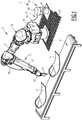
Figure 1 est une vue en perspective d'une installation d'application d'un produit fluide sur un substrat comprenant un robot applicateur selon l'invention, - la
Figure 2 est une vue schématique d'un dispositif d'application du robot applicateur de laFigure 1 , et - les
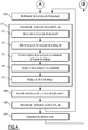
Figures 3 et4 sont des diagrammes en blocs illustrant un procédé mis en oeuvre par l'installation d'application de laFigure 1 . - L'installation 2 représentée sur la
Figure 1 est destinée à l'application d'un produit fluide sur des substrats 4. - Le produit fluide est typiquement constitué par un produit à haute viscosité, c'est-à-dire dont la viscosité est supérieure à 3000 mPa.s. Des exemples de tels produits à haute viscosité sont typiquement des mastics ou des colles élastomères ou epoxy. Avantageusement, le produit fluide a une viscosité comprise entre 3000 et 300000 Pa.s.
- Les substrats 4 sont ici constitués par des plaques préformées, typiquement par des plaques de tôle embouties.
- A cet effet, l'installation 2 comprend, de façon connue, un système 6 de déplacement des substrats 4 et un robot applicateur 8 pour l'application du produit fluide sur les substrats 4.
- Le système de déplacement 6 est configuré pour déplacer les substrats 4 à l'intérieur de l'installation 2 en immobilisant chaque substrat 4 relativement au plancher 10 de l'installation 2, pendant une durée prédéterminée, dans un périmètre d'action du robot applicateur 8.
- Dans l'exemple représenté, le système de déplacement 6 est constitué par un tapis d'entraînement portant les substrats 4.
- Le robot applicateur 8 comprend un robot multiaxe 12, une baie de contrôle 14 pour la commande du robot 12, un dispositif d'application 16 pour l'application du produit fluide sur les substrats 4, une armoire de commande 18 pour la commande du dispositif d'application 12, et un système d'alimentation 19 pour l'alimentation du dispositif d'application 16 avec le produit fluide.
- Le robot multiaxe 12 comprend, de manière connue, un bâti (non représenté) fixe relativement au plancher 10, un bras articulé 20 formé d'une pluralité de segments 22 articulés les uns aux autres, et un poignet 24 monté à une extrémité du bras articulé 20.
- Le poignet 24 comprend une extrémité proximale (non représentée) par laquelle il est relié à l'un des segments 22 du bras 20, et une extrémité distale (non représentée) opposée à l'extrémité proximale.
- Le robot multiaxe 12 comprend également une pluralité de moteurs (non représentés), montés à l'interface entre les segments 22 du bras 20 et avec le poignet 24, pour entraîner la rotation desdits segments 22 et dudit poignet 24 les uns par rapport aux autres.
- La baie de contrôle 14 comprend des circuits électriques (non représentés) pour déterminer une consigne de commande de chaque moteur du robot 12 et fournir cette consigne de commande à chaque moteur concerné.
- En référence à la
Figure 2 , le dispositif d'application 16 comprend un organe d'application 30 destiné à la mise en forme du produit fluide en vue de son application sur le substrat. A cet effet, l'organe d'application 30 comprend un orifice de sortie 32 pour la sortie du produit fluide hors du dispositif d'application 16, cet orifice de sortie 32 étant typiquement constitué par une buse. - Le dispositif d'application 16 comprend également un dispositif de mesure de vitesse 34, un organe de réglage 36 apte à régler un débit de dosage du produit fluide à travers l'orifice de sortie 32, et un module de commande 38 pour déterminer une consigne de commande en débit de l'organe de réglage 36 et fournir cette consigne de commande à l'organe de réglage 36.
- Le dispositif de mesure de vitesse 34 est apte à déterminer une vitesse mesurée de l'orifice de sortie 32 relativement à un référentiel inertiel, en particulier relativement au plancher 10 de l'installation 2. A cet effet, le dispositif de mesure de vitesse 34 est typiquement constitué par une centrale à inertie comprenant :
- trois accéléromètres 40, chacun apte à mesurer une accélération selon une direction propre orthogonale à la direction de mesure d'accélération de chaque autre accéléromètre 40,
- un gyroscope 42, apte à mesurer une vitesse angulaire autour de chacun de trois axes de rotation orthogonaux les uns aux autres, et
- un magnétomètre 44 apte à mesurer les trois composantes d'un champ magnétique au niveau dudit magnétomètre 44.
- Chaque accéléromètre 40 et chaque gyroscope 42 est typiquement constitué par un microsystème électromécanique inertiel.
- Les accéléromètres 40, le gyroscope 42 et le magnétomètre 44 sont typiquement intégrés dans une carte électronique commune (non représentée).
- L'intégralité du dispositif de mesure de vitesse 34 est à une distance de l'orifice de sortie 32 inférieure à 15 cm. Ainsi, les mouvements mesurés par le dispositif de mesure de vitesse 34 sont très proches des mouvements de l'orifice de sortie 32.
- A cet effet, le dispositif de mesure de vitesse 34 est, comme représenté, monté sur l'organe d'application 30.
- Le dispositif de mesure de vitesse 34 est configuré pour transmettre la vitesse mesurée au module de commande 38.
- L'organe de réglage 36 est apte à définir le débit de dosage du produit fluide à travers l'orifice de sortie 32, ledit débit de dosage étant fonction de la consigne de commande en débit fournie par le module de commande 38. A cet effet, l'organe de réglage 36 est typiquement constitué par une pompe alimentant l'organe d'application 30, le débit du produit fluide en sortie de ladite pompe constituant le débit de dosage.
- Par exemple, l'organe de réglage 36 est constitué par une pompe à simple ou double effet comprenant une chambre et un piston (non représentés), la vitesse de déplacement du piston dans la chambre déterminant le débit de dosage. En variante, l'organe de réglage 36 est constitué par une pompe à pistons axiaux dont la vitesse de rotation détermine le débit de dosage.
- L'organe de réglage 36 est à une distance de l'orifice de sortie 32 inférieure à 15cm. Ainsi, les variations du débit de sortie de la pompe se répercutent de manière presque instantanée sur le débit de dosage.
- Le module de commande 38 est configuré pour déterminer la consigne de commande en débit en fonction de la vitesse mesurée, et pour adapter cette consigne de sorte que le rapport entre le débit de dosage du produit fluide et la vitesse mesurée de l'orifice de sortie 32 soit sensiblement constant.
- A cet effet, le module de commande 38 est adapté pour recevoir du dispositif de mesure 34 la vitesse mesurée, et pour déduire de cette vitesse mesurée la consigne de commande en débit. Pour ce faire, le module de commande 38 est typiquement réalisé sous forme de composants logiques programmables et/ou de circuits intégrés dédiés inclus dans le dispositif d'application 16.
- L'intégralité du module de commande 38 est à une distance du dispositif de mesure de vitesse 34 inférieure à 5cm et à une distance de l'organe de réglage 36 inférieure à 10cm. Ainsi, les échanges d'informations entre le module de commande 38 et chacun des dispositif de mesure de vitesse 34 et organe de réglage 36 sont presque instantanés, ce qui permet une très grande réactivité de l'organe de réglage 36 suite aux variations de vitesse de l'orifice de sortie déterminées par le dispositif de mesure 34.
- Dans l'exemple représenté, l'organe d'application 30, le dispositif de mesure de vitesse 34, l'organe de réglage 36 et le module de commande 38 sont tous intégrés à un même boîtier 46 monté sur le poignet 24 du bras articulé 20. En variante, au moins une partie du dispositif d'application 16 n'est pas montée sur le poignet 24 : par exemple, l'organe de réglage 36 est monté sur le segment 22 du bras articulé 20 le plus proche du poignet 24.
- Quel que soit le montage du dispositif d'application 16, l'organe d'application 30 est de préférence toujours monté à l'extrémité distale du poignet 24.
- De retour à la
Figure 1 , le système d'alimentation 19 comprend une cuve 50 contenant le produit fluide, et un système de transfert fluidique 52 pour transférer le produit fluide contenu dans la cuve 50 à une entrée 54 (Figure 2 ) de l'organe de réglage 36. - Le système de transfert fluidique 52 est adapté pour fournir le produit fluide au dispositif d'application 16 à une pression supérieure à 1,1 fois la pression atmosphérique. A cet effet, le système de transfert fluidique 52 comprend un groupe élévateur 56 pour pomper le produit fluide dans la cuve 50, et une conduite 58 reliant fluidiquement une sortie (non représentée) du groupe élévateur 56 à l'entrée 54 de l'organe de réglage 36.
- Un procédé 100 d'application du produit fluide au moyen de l'installation 2 va maintenant être décrit, en référence à la
Figure 3 . - Tout d'abord, au cours d'une première étape 110, l'installation 2 et les substrats 4 sont fournis.
- Cette étape 110 est suivie d'une étape 120 d'initialisation.
- Cette étape 120 comprend une première sous-étape lors de laquelle le groupe élévateur 56 est activé. Celui-ci se met alors à pomper le produit dans la cuve 50 et à le refouler dans la conduite 58.
- L'étape 120 comprend également une deuxième sous-étape, sensiblement simultanée avec la première sous-étape, lors de laquelle le dispositif de mesure 34 est activé. A compter de cette sous-étape, le dispositif de mesure 34 mesure continûment la vitesse de l'orifice de sortie 32.
- Ensuite, lors d'une étape 130, un substrat 4 est apporté par le système de déplacement 6 dans le périmètre d'action du robot applicateur 8, puis immobilisé dans ledit périmètre d'action.
- La baie de contrôle 14 commande alors, lors d'une étape 140, le déplacement du bras articulé 20 de façon à venir placer l'orifice de sortie 32 du dispositif d'application 16 en vis-à-vis d'une surface à recouvrir du substrat 4, à une distance adaptée pour l'application du produit fluide sur ladite surface.
- Puis, lors d'une étape 150, le robot applicateur 8 amorce l'application du produit fluide sur le substrat 4.
- Tout au long de cette étape 150, l'orifice de sortie 32 est déplacé par le robot 12, relativement au plancher 10, à une première vitesse, en suivant la surface à recouvrir, et une consigne est communiquée par l'armoire de commande 18 au dispositif d'application 16 pour l'application du produit fluide.
- L'étape 150 comprend une première sous-étape 152 lors de laquelle la première vitesse est mesurée par le dispositif de mesure 34.
- Ensuite, lors d'une sous-étape 154, le module de commande 38 détermine une première consigne de commande de l'organe de réglage 36 fonction de ladite première vitesse et communique cette première consigne de commande à l'organe de réglage 36 lors d'une sous-étape 156.
- Cette consigne de commande est reçue par l'organe de réglage 36 lors d'une sous-étape 158, suite à laquelle l'organe de réglage 36 règle le débit de dosage à un premier débit lors d'une sous-étape 159. Ce premier débit est tel que le rapport dudit premier débit sur la première vitesse est égal à une constante prédéterminée.
- Le produit fluide est ensuite appliqué avec un débit de dosage égal au premier débit pendant toute la suite de l'étape 150.
- Puis, lors d'une étape 160, le robot 12 modifie la vitesse de déplacement de l'orifice de sortie 32 relativement au plancher 10. Ce changement de vitesse consiste typiquement en un ralentissement survenant lors d'un changement de la direction de déplacement de l'orifice de sortie 32.
- L'étape 160 est ainsi suivie d'une étape 170 de poursuite de l'application du produit fluide sur le substrat 4 à une vitesse modifiée.
- Tout au long de cette étape 170, l'orifice de sortie 32 est déplacé par le robot 12, relativement au plancher 10, à la vitesse modifiée, en suivant la surface à recouvrir, et une consigne est communiquée par l'armoire de commande 18 au dispositif d'application 16 pour l'application du produit fluide.
- L'étape 170 comprend une première sous-étape 172 lors de laquelle la vitesse modifiée est mesurée par le dispositif de mesure 34.
- Ensuite, lors d'une sous-étape 174, le module de commande 38 détermine une nouvelle consigne de commande de l'organe de réglage 36 fonction de ladite vitesse modifiée et communique cette nouvelle consigne de commande à l'organe de réglage 36 lors d'une sous-étape 176.
- Cette nouvelle consigne de commande est reçue par l'organe de réglage 36 lors d'une sous-étape 178, suite à laquelle l'organe de réglage 36 règle, lors d'une sous-étape 179, le débit de dosage à un nouveau débit. Ce nouveau débit est tel que le rapport dudit nouveau débit sur la vitesse modifiée est égal à ladite constante prédéterminée.
- Le produit fluide est ensuite appliqué avec un débit de dosage égal au nouveau débit pendant toute la suite de l'étape 170. Il en résulte une application du produit fluide qui est homogène avec l'application précédemment réalisée.
- Puis, lors d'une étape 180, le robot 12 modifie à nouveau la vitesse de déplacement de l'orifice de sortie 32. Ce changement de vitesse consiste typiquement en une accélération faisant suite au changement de la direction de déplacement de l'orifice de sortie 32 survenu lors des étapes 160 et 170.
- L'étape 180 est ainsi suivie d'une nouvelle étape 190 de poursuite de l'application du produit fluide sur le substrat 4 à une vitesse modifiée. Cette étape 190 est identique à l'étape 170.
- Les étapes 160, 170, 180 et 190 sont répétées à chaque changement de la direction de déplacement de l'orifice de sortie 32.
- Finalement, une fois l'intégralité de la surface à recouvrir recouverte avec du produit fluide, le substrat 4 est évacué par le système de déplacement 6 hors du périmètre d'action du robot applicateur 8 lors d'une étape 200.
- Les étapes 130 à 200 sont ensuite répétées jusqu'à ce que tous les substrats 4 aient été traités par le robot applicateur 8.
- Grâce à l'invention décrite ci-dessus, il est ainsi possible d'appliquer un produit fluide sur une surface à recouvrir de manière homogène, indépendamment de la vitesse de déplacement de l'orifice de sortie du produit fluide relativement à ladite surface et indépendamment des moyens employés pour déplacer ledit orifice de sortie.
- Cette solution est ainsi polyvalente. Elle est en outre économique, puisqu'elle permet la réutilisation de robots multiaxes non équipés d'un module de communication de la vitesse pointe outil estimée.
- Dans l'exemple décrit ci-dessus, le robot applicateur 8 est adapté pour l'application d'un seul produit fluide à la fois. En variante (non représentée), le robot applicateur 8 est adapté pour l'application de plusieurs produits fluides simultanément. Dans ce cas, le robot applicateur 8 comprend, outre le système d'alimentation 19, au moins un autre système d'alimentation, un par produit fluide, pour alimenter le dispositif d'application 16 avec chacun de ces produits fluides. En outre, le dispositif d'application 16 comprend alors un organe de réglage 36 pour chaque produit fluide, le module de commande 38 étant configuré pour produire pour chacun de ces organes de réglage une consigne de commande fonction de la vitesse mesurée par le dispositif de mesure de vitesse 34.
Claims (15)
- Dispositif d'application (16) pour l'application d'au moins un produit fluide sur un substrat (4), le dispositif d'application (16) comprenant :- un organe d'application (30), pour la mise en forme du ou de chaque produit fluide en vue de son application sur le substrat (4), l'organe d'application (30) présentant un orifice (32) de sortie du ou des produit(s) fluide(s) hors du dispositif d'application (16),- pour au moins un produit fluide, un organe de réglage (36) apte à régler un débit de dosage du produit fluide à travers l'orifice de sortie (32) en fonction d'une consigne de commande dudit organe de réglage (36), et- un module de commande (38) pour déterminer la consigne de commande et la fournir à l'organe de réglage (36),caractérisé en ce que le dispositif d'application (16) comprend également un dispositif de mesure de vitesse (34) apte à déterminer une vitesse mesurée de l'orifice de sortie (32) relativement à un référentiel inertiel, et en ce que le module de commande (38) est configuré pour déterminer la consigne de commande en fonction de ladite vitesse mesurée.
- Dispositif d'application (16) selon la revendication 1, dans lequel la consigne de commande est adaptée pour que le rapport entre le débit de dosage du produit fluide et la vitesse mesurée de l'orifice de sortie soit sensiblement constant.
- Dispositif d'application (16) selon la revendication 1 ou 2, dans lequel le dispositif de mesure de vitesse (34) comprend au moins un accéléromètre (40).
- Dispositif d'application (16) selon l'une quelconque des revendications précédentes, dans lequel le dispositif de mesure de vitesse (34) comprend au moins un gyroscope (42).
- Dispositif d'application (16) selon l'une quelconque des revendications précédentes, dans lequel le dispositif de mesure de vitesse (34) comprend un magnétomètre (44).
- Dispositif d'application (16) selon l'une quelconque des revendications précédentes, dans lequel le dispositif de mesure de vitesse (34) est à une distance de l'orifice de sortie (32) inférieure à 15 cm.
- Dispositif d'application (16) selon l'une quelconque des revendications précédentes, dans lequel le module de commande (38) est à une distance du dispositif de mesure de vitesse (34) inférieure à 5 cm.
- Dispositif d'application (16) selon l'une quelconque des revendications précédentes, dans lequel le module de commande (38) est à une distance de l'organe de réglage (36) inférieure à 10 cm.
- Dispositif d'application (16) selon l'une quelconque des revendications précédentes, dans lequel l'organe de réglage (36) est à une distance de l'orifice de sortie (32) inférieure à 15 cm.
- Dispositif d'application (16) selon l'une quelconque des revendications précédentes, dans lequel le produit fluide a une viscosité comprise entre 3000 et 300000 mPa.s.
- Robot applicateur (8) pour l'application d'un produit fluide sur un substrat (4), le robot applicateur (8) comprenant un bâti, un bras articulé (20) formé d'une pluralité de segments (22) articulés les uns aux autres, un poignet (24) monté à une extrémité du bras articulé (20), et un dispositif d'application (16) selon l'une quelconque des revendications précédentes dont l'organe d'application (30) est monté à une extrémité distale du poignet (24).
- Robot applicateur (8) selon la revendication 11, dans lequel le module de commande (38) est monté sur le poignet (24) ou sur le segment (22) le plus proche du poignet (24).
- Robot applicateur (8) selon la revendication 11 ou 12, dans lequel le dispositif de mesure de vitesse (34) est monté sur l'organe d'application (30).
- Robot applicateur (8) selon l'une quelconque des revendications 11 à 13, dans lequel la vitesse mesurée est constituée par la vitesse de l'orifice de sortie (32) relativement au bâti.
- Procédé (100) d'application d'un produit fluide sur un substrat (4), caractérisé en ce qu'il comprend les étapes successives suivantes :- fourniture (110) d'un dispositif d'application (16) selon l'une quelconque des revendications 1 à 10,- dosage (159) du produit fluide à travers l'orifice de sortie (32) à un premier débit de dosage, l'orifice de sortie (32) se déplaçant à une première vitesse,- changement (160) de vitesse de l'orifice de sortie (32), et- dosage (179) du produit fluide à travers l'orifice de sortie (32) à un deuxième débit de dosage différent du premier débit de dosage.
Applications Claiming Priority (1)
| Application Number | Priority Date | Filing Date | Title |
|---|---|---|---|
| FR1852232A FR3078900B1 (fr) | 2018-03-15 | 2018-03-15 | Dispositif d'application d'un produit fluide dont le debit de dosage depend de la vitesse d'un orifice de sortie dudit produit fluide |
Publications (2)
| Publication Number | Publication Date |
|---|---|
| EP3539675A1 true EP3539675A1 (fr) | 2019-09-18 |
| EP3539675B1 EP3539675B1 (fr) | 2021-10-13 |
Family
ID=62816699
Family Applications (1)
| Application Number | Title | Priority Date | Filing Date |
|---|---|---|---|
| EP19162989.8A Active EP3539675B1 (fr) | 2018-03-15 | 2019-03-14 | Dispositif d'application d'un produit fluide dont le débit de dosage dépend de la vitesse d'un orifice de sortie dudit produit fluide |
Country Status (7)
| Country | Link |
|---|---|
| US (1) | US20190283062A1 (fr) |
| EP (1) | EP3539675B1 (fr) |
| JP (1) | JP7432992B2 (fr) |
| KR (1) | KR102659282B1 (fr) |
| CN (1) | CN110270471B (fr) |
| ES (1) | ES2898873T3 (fr) |
| FR (1) | FR3078900B1 (fr) |
Cited By (3)
| Publication number | Priority date | Publication date | Assignee | Title |
|---|---|---|---|---|
| CN111729791A (zh) * | 2020-07-06 | 2020-10-02 | 深圳市巨豪自动化设备有限公司 | 一种机器人自动化喷涂线 |
| CN113477465A (zh) * | 2021-07-02 | 2021-10-08 | 广东嘉尚新能源科技有限公司 | 一种可均匀出胶并对余胶进行清理的软包锂电芯侧边封胶装置 |
| US20230270079A1 (en) * | 2020-07-17 | 2023-08-31 | Desvac | Method and apparatus for delivering fluid droplets onto an open and stationary tray |
Families Citing this family (5)
| Publication number | Priority date | Publication date | Assignee | Title |
|---|---|---|---|---|
| WO2020150469A1 (fr) * | 2019-01-18 | 2020-07-23 | Wagner Spray Tech Corporation | Commande intelligente de système de pulvérisation |
| US11513602B2 (en) | 2019-09-10 | 2022-11-29 | Wagner Spray Tech Corporation | Gesture control of a fluid application system |
| DE102020000412A1 (de) * | 2020-01-24 | 2021-07-29 | bdtronic GmbH | Dosiervorrichtung sowie Verfahren zur dosierten Abgabe eines Mediums |
| CN112620002A (zh) * | 2020-11-10 | 2021-04-09 | 江华飞信达科技有限公司 | 全自动点胶生产线 |
| CN113477466B (zh) * | 2021-08-12 | 2022-03-22 | 绍兴欧柏斯光电科技有限公司 | 一种晶片点胶装置以及工艺 |
Citations (5)
| Publication number | Priority date | Publication date | Assignee | Title |
|---|---|---|---|---|
| US4013037A (en) * | 1975-03-27 | 1977-03-22 | Airprint Systems, Inc. | Apparatus for controllably applying liquids to a moving surface |
| US5054650A (en) * | 1986-10-30 | 1991-10-08 | Nordson Corporation | Method of compensating for changes in the flow characteristics of a dispensed fluid to maintain the volume of dispensed fluid at a setpoint |
| US20050048196A1 (en) * | 2003-08-26 | 2005-03-03 | Akihiro Yanagita | Control and system for dispensing fluid material |
| US8886980B2 (en) * | 2010-03-29 | 2014-11-11 | Qualcomm Incorporated | Power efficient way of operating motion sensors |
| US20160052296A1 (en) * | 2013-02-25 | 2016-02-25 | John Grimes | Automated Paint Application System and Related Method |
Family Cites Families (24)
| Publication number | Priority date | Publication date | Assignee | Title |
|---|---|---|---|---|
| JPS6051911A (ja) * | 1983-08-31 | 1985-03-23 | Hitachi Ltd | ロボツト制御装置 |
| JPH01184061A (ja) * | 1988-01-14 | 1989-07-21 | Nissan Motor Co Ltd | 粘性材料塗布装置 |
| US6361600B1 (en) * | 1998-08-04 | 2002-03-26 | Tokyo Electron Limited | Film forming apparatus and film forming method |
| JP2000271888A (ja) * | 1999-03-25 | 2000-10-03 | Fanuc Ltd | ロボット制御装置 |
| ES2264892B1 (es) * | 2005-07-04 | 2007-12-16 | Index Servicios De Ingenieria, S.L. | Sistema automatico de aplicacion de un fluido solidificable. |
| JP4879070B2 (ja) * | 2007-03-30 | 2012-02-15 | 富士フイルム株式会社 | 塗布装置、及び塗布方法 |
| WO2009115201A2 (fr) * | 2008-03-20 | 2009-09-24 | Dürr Systems GmbH | Robot de peinture et procédé d'utilisation correspondant |
| DE102008015834A1 (de) * | 2008-03-27 | 2009-10-01 | Inos Automationssoftware Gmbh | Verfahren und Vorrichtung zum automatischen Einbringen oder Auftragen von zähflüssigem Material |
| CN101352854B (zh) * | 2008-07-17 | 2011-01-26 | 上海交通大学 | 遥操作平面冗余度机械臂自主避障智能单元、系统及方法 |
| US8442766B2 (en) * | 2008-10-02 | 2013-05-14 | Certusview Technologies, Llc | Marking apparatus having enhanced features for underground facility marking operations, and associated methods and systems |
| US20100300355A1 (en) * | 2009-06-01 | 2010-12-02 | Moser Baer India Limited | Printing material profiles onto substrates |
| CA2771286C (fr) * | 2009-08-11 | 2016-08-30 | Certusview Technologies, Llc | Localisation d'un equipement en liaison avec un dispositif de communication mobile et/ou portatif ou, encore, muni d'un tel dispositif |
| DE102012006370A1 (de) | 2012-03-29 | 2013-10-02 | Heidelberger Druckmaschinen Aktiengesellschaft | System zum Bedrucken eines Objekts |
| US20140238296A1 (en) * | 2013-02-25 | 2014-08-28 | John F. Grimes | Automated Paint Application System |
| JP6267141B2 (ja) * | 2014-06-04 | 2018-01-24 | 東京エレクトロン株式会社 | 液塗布方法、液塗布装置、及びコンピュータ読み取り可能な記録媒体 |
| EP2962766B1 (fr) * | 2014-06-30 | 2016-11-23 | ABB Schweiz AG | Système et procédé de détermination de temps morts relatifs aux composants pour l'application par pulvérisation robotisée de fluides visqueux |
| FI126677B (en) * | 2014-07-17 | 2017-03-31 | Johannes Vähänen | INJECTOR, REMOTE CONTROL TOOL AND METHOD OF CONTROL INJECTION DIRECTION OF INJECTOR |
| US9505017B2 (en) * | 2014-08-04 | 2016-11-29 | GM Global Technology Operations LLC | Rotary paint atomizer system and method of monitoring a rotary paint atomizer |
| JP6642054B2 (ja) * | 2015-03-19 | 2020-02-05 | 株式会社デンソーウェーブ | ロボット操作装置、及びロボット操作プログラム |
| JP2016215111A (ja) * | 2015-05-19 | 2016-12-22 | アズビル株式会社 | 塗布装置、塗布制御装置および塗布制御方法 |
| CN110624717A (zh) * | 2015-06-01 | 2019-12-31 | 深圳市大疆创新科技有限公司 | 具有液体流量和转速的反馈的喷洒系统 |
| JP6830206B2 (ja) * | 2016-06-13 | 2021-02-17 | パナソニックIpマネジメント株式会社 | 機器制御システム、情報処理装置および機器制御方法 |
| TWI598286B (zh) * | 2016-06-29 | 2017-09-11 | 立錡科技股份有限公司 | 流體配送器、流體配送控制裝置以及流體配送異常監控裝置 |
| CN106426084B (zh) * | 2016-10-14 | 2018-09-04 | 广州励丰文化科技股份有限公司 | 一种远程媒体与超声波测距结合的机械臂控制台及方法 |
-
2018
- 2018-03-15 FR FR1852232A patent/FR3078900B1/fr active Active
-
2019
- 2019-03-13 KR KR1020190028640A patent/KR102659282B1/ko active Active
- 2019-03-13 US US16/352,289 patent/US20190283062A1/en not_active Abandoned
- 2019-03-14 EP EP19162989.8A patent/EP3539675B1/fr active Active
- 2019-03-14 JP JP2019046861A patent/JP7432992B2/ja active Active
- 2019-03-14 ES ES19162989T patent/ES2898873T3/es active Active
- 2019-03-15 CN CN201910197993.9A patent/CN110270471B/zh active Active
Patent Citations (5)
| Publication number | Priority date | Publication date | Assignee | Title |
|---|---|---|---|---|
| US4013037A (en) * | 1975-03-27 | 1977-03-22 | Airprint Systems, Inc. | Apparatus for controllably applying liquids to a moving surface |
| US5054650A (en) * | 1986-10-30 | 1991-10-08 | Nordson Corporation | Method of compensating for changes in the flow characteristics of a dispensed fluid to maintain the volume of dispensed fluid at a setpoint |
| US20050048196A1 (en) * | 2003-08-26 | 2005-03-03 | Akihiro Yanagita | Control and system for dispensing fluid material |
| US8886980B2 (en) * | 2010-03-29 | 2014-11-11 | Qualcomm Incorporated | Power efficient way of operating motion sensors |
| US20160052296A1 (en) * | 2013-02-25 | 2016-02-25 | John Grimes | Automated Paint Application System and Related Method |
Cited By (4)
| Publication number | Priority date | Publication date | Assignee | Title |
|---|---|---|---|---|
| CN111729791A (zh) * | 2020-07-06 | 2020-10-02 | 深圳市巨豪自动化设备有限公司 | 一种机器人自动化喷涂线 |
| US20230270079A1 (en) * | 2020-07-17 | 2023-08-31 | Desvac | Method and apparatus for delivering fluid droplets onto an open and stationary tray |
| CN113477465A (zh) * | 2021-07-02 | 2021-10-08 | 广东嘉尚新能源科技有限公司 | 一种可均匀出胶并对余胶进行清理的软包锂电芯侧边封胶装置 |
| CN113477465B (zh) * | 2021-07-02 | 2022-05-20 | 广东嘉尚新能源科技有限公司 | 一种可均匀出胶并对余胶进行清理的软包锂电芯侧边封胶装置 |
Also Published As
| Publication number | Publication date |
|---|---|
| EP3539675B1 (fr) | 2021-10-13 |
| CN110270471A (zh) | 2019-09-24 |
| CN110270471B (zh) | 2022-06-28 |
| KR20190109268A (ko) | 2019-09-25 |
| FR3078900A1 (fr) | 2019-09-20 |
| JP2019155360A (ja) | 2019-09-19 |
| KR102659282B1 (ko) | 2024-04-22 |
| ES2898873T3 (es) | 2022-03-09 |
| US20190283062A1 (en) | 2019-09-19 |
| FR3078900B1 (fr) | 2020-09-18 |
| JP7432992B2 (ja) | 2024-02-19 |
Similar Documents
| Publication | Publication Date | Title |
|---|---|---|
| EP3539675B1 (fr) | Dispositif d'application d'un produit fluide dont le débit de dosage dépend de la vitesse d'un orifice de sortie dudit produit fluide | |
| US10814344B1 (en) | Fluid dispense pump with drip prevention mechanism and method for controlling same | |
| EP2139604B1 (fr) | Organe de pulverisation, dispositif de projection comportant un tel organe, installation de projection et methode de nettoyage d'un tel organe | |
| EP0746422B1 (fr) | Dispositif d'application d'un produit liquide | |
| EP0292354B1 (fr) | Installation de projection de produit de revêtement, à pompe | |
| EP1303359A1 (fr) | Procede et station de changement de produit dans une installation de projection de produit de revetement | |
| JP2012524864A (ja) | ポンプ | |
| EP2429716A1 (fr) | Projecteur et organe de pulverisation de produit de revetement et procede de projection mettant en oeuvre un tel projecteur | |
| EP2355934B1 (fr) | Projecteur de produit de revetement et procede pour reapprovisionner un tel projecteur en produit de revetement | |
| JP2008253927A (ja) | 間欠塗布方法及び間欠塗布装置 | |
| WO2016140095A1 (fr) | Procédé et dispositif d'application de graisse | |
| WO2002032586A1 (fr) | Dispositif et procede d'alimentation de projecteurs et installation de projection equipee d'un tel dispositif | |
| EP3953290A1 (fr) | Dispositif de remplissage de recipients | |
| KR20190038242A (ko) | 기판의 도포 방법 및 기판의 도포 장치 | |
| EP3612321A1 (fr) | Dispositif comprenant une pompe à pistons axiaux pour l'application d'un produit fluide sur un substrat | |
| CN107899895A (zh) | 电子加工用胶液离心脱泡装置 | |
| JP4320813B2 (ja) | 転がり軸受への潤滑油塗布方法及び潤滑油塗布装置 | |
| KR20120081942A (ko) | 약액 토출 밸브 및 약액 공급 시스템 | |
| EP4292717B1 (fr) | Installation d'application de produit de revêtement et procédé de commande d'une telle installation | |
| WO1997041965A1 (fr) | Dispositif de pulverisation du type biphasique pour un produit fluide ou pateux | |
| JP3205975U (ja) | 塗布装置 | |
| EP4478399A1 (fr) | Procédé d'alimentation en fluide de traitement et dispositif de traitement de substrat | |
| JPH11276972A (ja) | レジストコーティング装置 | |
| KR19990085144A (ko) | 에치엠디에스 공급장비 | |
| JPH0826849B2 (ja) | サツクバツクバルブ |
Legal Events
| Date | Code | Title | Description |
|---|---|---|---|
| PUAI | Public reference made under article 153(3) epc to a published international application that has entered the european phase |
Free format text: ORIGINAL CODE: 0009012 |
|
| STAA | Information on the status of an ep patent application or granted ep patent |
Free format text: STATUS: THE APPLICATION HAS BEEN PUBLISHED |
|
| AK | Designated contracting states |
Kind code of ref document: A1 Designated state(s): AL AT BE BG CH CY CZ DE DK EE ES FI FR GB GR HR HU IE IS IT LI LT LU LV MC MK MT NL NO PL PT RO RS SE SI SK SM TR |
|
| AX | Request for extension of the european patent |
Extension state: BA ME |
|
| STAA | Information on the status of an ep patent application or granted ep patent |
Free format text: STATUS: REQUEST FOR EXAMINATION WAS MADE |
|
| 17P | Request for examination filed |
Effective date: 20200227 |
|
| RBV | Designated contracting states (corrected) |
Designated state(s): AL AT BE BG CH CY CZ DE DK EE ES FI FR GB GR HR HU IE IS IT LI LT LU LV MC MK MT NL NO PL PT RO RS SE SI SK SM TR |
|
| STAA | Information on the status of an ep patent application or granted ep patent |
Free format text: STATUS: EXAMINATION IS IN PROGRESS |
|
| 17Q | First examination report despatched |
Effective date: 20201002 |
|
| GRAP | Despatch of communication of intention to grant a patent |
Free format text: ORIGINAL CODE: EPIDOSNIGR1 |
|
| STAA | Information on the status of an ep patent application or granted ep patent |
Free format text: STATUS: GRANT OF PATENT IS INTENDED |
|
| RIC1 | Information provided on ipc code assigned before grant |
Ipc: B05B 13/04 20060101AFI20210420BHEP Ipc: B05C 5/02 20060101ALI20210420BHEP Ipc: B25J 9/08 20060101ALI20210420BHEP Ipc: B25J 9/00 20060101ALI20210420BHEP Ipc: B05C 11/10 20060101ALI20210420BHEP Ipc: B25J 11/00 20060101ALI20210420BHEP Ipc: B25J 13/08 20060101ALI20210420BHEP Ipc: B05B 13/02 20060101ALN20210420BHEP |
|
| INTG | Intention to grant announced |
Effective date: 20210510 |
|
| GRAS | Grant fee paid |
Free format text: ORIGINAL CODE: EPIDOSNIGR3 |
|
| GRAA | (expected) grant |
Free format text: ORIGINAL CODE: 0009210 |
|
| STAA | Information on the status of an ep patent application or granted ep patent |
Free format text: STATUS: THE PATENT HAS BEEN GRANTED |
|
| AK | Designated contracting states |
Kind code of ref document: B1 Designated state(s): AL AT BE BG CH CY CZ DE DK EE ES FI FR GB GR HR HU IE IS IT LI LT LU LV MC MK MT NL NO PL PT RO RS SE SI SK SM TR |
|
| REG | Reference to a national code |
Ref country code: GB Ref legal event code: FG4D Free format text: NOT ENGLISH |
|
| REG | Reference to a national code |
Ref country code: CH Ref legal event code: EP |
|
| REG | Reference to a national code |
Ref country code: DE Ref legal event code: R096 Ref document number: 602019008250 Country of ref document: DE |
|
| REG | Reference to a national code |
Ref country code: IE Ref legal event code: FG4D Free format text: LANGUAGE OF EP DOCUMENT: FRENCH |
|
| REG | Reference to a national code |
Ref country code: AT Ref legal event code: REF Ref document number: 1437785 Country of ref document: AT Kind code of ref document: T Effective date: 20211115 |
|
| REG | Reference to a national code |
Ref country code: LT Ref legal event code: MG9D |
|
| REG | Reference to a national code |
Ref country code: NL Ref legal event code: MP Effective date: 20211013 |
|
| REG | Reference to a national code |
Ref country code: ES Ref legal event code: FG2A Ref document number: 2898873 Country of ref document: ES Kind code of ref document: T3 Effective date: 20220309 |
|
| REG | Reference to a national code |
Ref country code: AT Ref legal event code: MK05 Ref document number: 1437785 Country of ref document: AT Kind code of ref document: T Effective date: 20211013 |
|
| PG25 | Lapsed in a contracting state [announced via postgrant information from national office to epo] |
Ref country code: RS Free format text: LAPSE BECAUSE OF FAILURE TO SUBMIT A TRANSLATION OF THE DESCRIPTION OR TO PAY THE FEE WITHIN THE PRESCRIBED TIME-LIMIT Effective date: 20211013 Ref country code: LT Free format text: LAPSE BECAUSE OF FAILURE TO SUBMIT A TRANSLATION OF THE DESCRIPTION OR TO PAY THE FEE WITHIN THE PRESCRIBED TIME-LIMIT Effective date: 20211013 Ref country code: FI Free format text: LAPSE BECAUSE OF FAILURE TO SUBMIT A TRANSLATION OF THE DESCRIPTION OR TO PAY THE FEE WITHIN THE PRESCRIBED TIME-LIMIT Effective date: 20211013 Ref country code: BG Free format text: LAPSE BECAUSE OF FAILURE TO SUBMIT A TRANSLATION OF THE DESCRIPTION OR TO PAY THE FEE WITHIN THE PRESCRIBED TIME-LIMIT Effective date: 20220113 Ref country code: AT Free format text: LAPSE BECAUSE OF FAILURE TO SUBMIT A TRANSLATION OF THE DESCRIPTION OR TO PAY THE FEE WITHIN THE PRESCRIBED TIME-LIMIT Effective date: 20211013 |
|
| PG25 | Lapsed in a contracting state [announced via postgrant information from national office to epo] |
Ref country code: IS Free format text: LAPSE BECAUSE OF FAILURE TO SUBMIT A TRANSLATION OF THE DESCRIPTION OR TO PAY THE FEE WITHIN THE PRESCRIBED TIME-LIMIT Effective date: 20220213 Ref country code: SE Free format text: LAPSE BECAUSE OF FAILURE TO SUBMIT A TRANSLATION OF THE DESCRIPTION OR TO PAY THE FEE WITHIN THE PRESCRIBED TIME-LIMIT Effective date: 20211013 Ref country code: PT Free format text: LAPSE BECAUSE OF FAILURE TO SUBMIT A TRANSLATION OF THE DESCRIPTION OR TO PAY THE FEE WITHIN THE PRESCRIBED TIME-LIMIT Effective date: 20220214 Ref country code: PL Free format text: LAPSE BECAUSE OF FAILURE TO SUBMIT A TRANSLATION OF THE DESCRIPTION OR TO PAY THE FEE WITHIN THE PRESCRIBED TIME-LIMIT Effective date: 20211013 Ref country code: NO Free format text: LAPSE BECAUSE OF FAILURE TO SUBMIT A TRANSLATION OF THE DESCRIPTION OR TO PAY THE FEE WITHIN THE PRESCRIBED TIME-LIMIT Effective date: 20220113 Ref country code: NL Free format text: LAPSE BECAUSE OF FAILURE TO SUBMIT A TRANSLATION OF THE DESCRIPTION OR TO PAY THE FEE WITHIN THE PRESCRIBED TIME-LIMIT Effective date: 20211013 Ref country code: LV Free format text: LAPSE BECAUSE OF FAILURE TO SUBMIT A TRANSLATION OF THE DESCRIPTION OR TO PAY THE FEE WITHIN THE PRESCRIBED TIME-LIMIT Effective date: 20211013 Ref country code: HR Free format text: LAPSE BECAUSE OF FAILURE TO SUBMIT A TRANSLATION OF THE DESCRIPTION OR TO PAY THE FEE WITHIN THE PRESCRIBED TIME-LIMIT Effective date: 20211013 Ref country code: GR Free format text: LAPSE BECAUSE OF FAILURE TO SUBMIT A TRANSLATION OF THE DESCRIPTION OR TO PAY THE FEE WITHIN THE PRESCRIBED TIME-LIMIT Effective date: 20220114 |
|
| REG | Reference to a national code |
Ref country code: DE Ref legal event code: R097 Ref document number: 602019008250 Country of ref document: DE |
|
| PG25 | Lapsed in a contracting state [announced via postgrant information from national office to epo] |
Ref country code: SM Free format text: LAPSE BECAUSE OF FAILURE TO SUBMIT A TRANSLATION OF THE DESCRIPTION OR TO PAY THE FEE WITHIN THE PRESCRIBED TIME-LIMIT Effective date: 20211013 Ref country code: SK Free format text: LAPSE BECAUSE OF FAILURE TO SUBMIT A TRANSLATION OF THE DESCRIPTION OR TO PAY THE FEE WITHIN THE PRESCRIBED TIME-LIMIT Effective date: 20211013 Ref country code: RO Free format text: LAPSE BECAUSE OF FAILURE TO SUBMIT A TRANSLATION OF THE DESCRIPTION OR TO PAY THE FEE WITHIN THE PRESCRIBED TIME-LIMIT Effective date: 20211013 Ref country code: EE Free format text: LAPSE BECAUSE OF FAILURE TO SUBMIT A TRANSLATION OF THE DESCRIPTION OR TO PAY THE FEE WITHIN THE PRESCRIBED TIME-LIMIT Effective date: 20211013 Ref country code: DK Free format text: LAPSE BECAUSE OF FAILURE TO SUBMIT A TRANSLATION OF THE DESCRIPTION OR TO PAY THE FEE WITHIN THE PRESCRIBED TIME-LIMIT Effective date: 20211013 Ref country code: CZ Free format text: LAPSE BECAUSE OF FAILURE TO SUBMIT A TRANSLATION OF THE DESCRIPTION OR TO PAY THE FEE WITHIN THE PRESCRIBED TIME-LIMIT Effective date: 20211013 |
|
| PLBE | No opposition filed within time limit |
Free format text: ORIGINAL CODE: 0009261 |
|
| STAA | Information on the status of an ep patent application or granted ep patent |
Free format text: STATUS: NO OPPOSITION FILED WITHIN TIME LIMIT |
|
| 26N | No opposition filed |
Effective date: 20220714 |
|
| PG25 | Lapsed in a contracting state [announced via postgrant information from national office to epo] |
Ref country code: MC Free format text: LAPSE BECAUSE OF FAILURE TO SUBMIT A TRANSLATION OF THE DESCRIPTION OR TO PAY THE FEE WITHIN THE PRESCRIBED TIME-LIMIT Effective date: 20211013 Ref country code: AL Free format text: LAPSE BECAUSE OF FAILURE TO SUBMIT A TRANSLATION OF THE DESCRIPTION OR TO PAY THE FEE WITHIN THE PRESCRIBED TIME-LIMIT Effective date: 20211013 |
|
| PG25 | Lapsed in a contracting state [announced via postgrant information from national office to epo] |
Ref country code: SI Free format text: LAPSE BECAUSE OF FAILURE TO SUBMIT A TRANSLATION OF THE DESCRIPTION OR TO PAY THE FEE WITHIN THE PRESCRIBED TIME-LIMIT Effective date: 20211013 |
|
| REG | Reference to a national code |
Ref country code: BE Ref legal event code: MM Effective date: 20220331 |
|
| PG25 | Lapsed in a contracting state [announced via postgrant information from national office to epo] |
Ref country code: LU Free format text: LAPSE BECAUSE OF NON-PAYMENT OF DUE FEES Effective date: 20220314 Ref country code: IE Free format text: LAPSE BECAUSE OF NON-PAYMENT OF DUE FEES Effective date: 20220314 |
|
| PG25 | Lapsed in a contracting state [announced via postgrant information from national office to epo] |
Ref country code: BE Free format text: LAPSE BECAUSE OF NON-PAYMENT OF DUE FEES Effective date: 20220331 |
|
| PG25 | Lapsed in a contracting state [announced via postgrant information from national office to epo] |
Ref country code: MK Free format text: LAPSE BECAUSE OF FAILURE TO SUBMIT A TRANSLATION OF THE DESCRIPTION OR TO PAY THE FEE WITHIN THE PRESCRIBED TIME-LIMIT Effective date: 20211013 Ref country code: CY Free format text: LAPSE BECAUSE OF FAILURE TO SUBMIT A TRANSLATION OF THE DESCRIPTION OR TO PAY THE FEE WITHIN THE PRESCRIBED TIME-LIMIT Effective date: 20211013 |
|
| PG25 | Lapsed in a contracting state [announced via postgrant information from national office to epo] |
Ref country code: HU Free format text: LAPSE BECAUSE OF FAILURE TO SUBMIT A TRANSLATION OF THE DESCRIPTION OR TO PAY THE FEE WITHIN THE PRESCRIBED TIME-LIMIT; INVALID AB INITIO Effective date: 20190314 |
|
| PG25 | Lapsed in a contracting state [announced via postgrant information from national office to epo] |
Ref country code: MT Free format text: LAPSE BECAUSE OF FAILURE TO SUBMIT A TRANSLATION OF THE DESCRIPTION OR TO PAY THE FEE WITHIN THE PRESCRIBED TIME-LIMIT Effective date: 20211013 |
|
| PGFP | Annual fee paid to national office [announced via postgrant information from national office to epo] |
Ref country code: IT Payment date: 20250310 Year of fee payment: 7 Ref country code: GB Payment date: 20250324 Year of fee payment: 7 |
|
| PGFP | Annual fee paid to national office [announced via postgrant information from national office to epo] |
Ref country code: TR Payment date: 20250306 Year of fee payment: 7 |
|
| PGFP | Annual fee paid to national office [announced via postgrant information from national office to epo] |
Ref country code: ES Payment date: 20250410 Year of fee payment: 7 |
|
| PGFP | Annual fee paid to national office [announced via postgrant information from national office to epo] |
Ref country code: CH Payment date: 20250401 Year of fee payment: 7 |
|
| REG | Reference to a national code |
Ref country code: CH Ref legal event code: R18 Free format text: ST27 STATUS EVENT CODE: U-0-0-R10-R18 (AS PROVIDED BY THE NATIONAL OFFICE) Effective date: 20260106 |
|
| PGFP | Annual fee paid to national office [announced via postgrant information from national office to epo] |
Ref country code: DE Payment date: 20260313 Year of fee payment: 8 |
|
| PGFP | Annual fee paid to national office [announced via postgrant information from national office to epo] |
Ref country code: FR Payment date: 20260330 Year of fee payment: 8 |