EP3533979A1 - Abgasreinigungsvorrichtung für verbrennungsmotor - Google Patents
Abgasreinigungsvorrichtung für verbrennungsmotor Download PDFInfo
- Publication number
- EP3533979A1 EP3533979A1 EP19160372.9A EP19160372A EP3533979A1 EP 3533979 A1 EP3533979 A1 EP 3533979A1 EP 19160372 A EP19160372 A EP 19160372A EP 3533979 A1 EP3533979 A1 EP 3533979A1
- Authority
- EP
- European Patent Office
- Prior art keywords
- scr catalyst
- exhaust gas
- reducing agent
- addition valve
- deterioration
- Prior art date
- Legal status (The legal status is an assumption and is not a legal conclusion. Google has not performed a legal analysis and makes no representation as to the accuracy of the status listed.)
- Withdrawn
Links
Images



Classifications
-
- F—MECHANICAL ENGINEERING; LIGHTING; HEATING; WEAPONS; BLASTING
- F01—MACHINES OR ENGINES IN GENERAL; ENGINE PLANTS IN GENERAL; STEAM ENGINES
- F01N—GAS-FLOW SILENCERS OR EXHAUST APPARATUS FOR MACHINES OR ENGINES IN GENERAL; GAS-FLOW SILENCERS OR EXHAUST APPARATUS FOR INTERNAL-COMBUSTION ENGINES
- F01N3/00—Exhaust or silencing apparatus having means for purifying, rendering innocuous, or otherwise treating exhaust
- F01N3/08—Exhaust or silencing apparatus having means for purifying, rendering innocuous, or otherwise treating exhaust for rendering innocuous
- F01N3/10—Exhaust or silencing apparatus having means for purifying, rendering innocuous, or otherwise treating exhaust for rendering innocuous by thermal or catalytic conversion of noxious components of exhaust
- F01N3/18—Exhaust or silencing apparatus having means for purifying, rendering innocuous, or otherwise treating exhaust for rendering innocuous by thermal or catalytic conversion of noxious components of exhaust characterised by methods of operation; Control
- F01N3/20—Exhaust or silencing apparatus having means for purifying, rendering innocuous, or otherwise treating exhaust for rendering innocuous by thermal or catalytic conversion of noxious components of exhaust characterised by methods of operation; Control specially adapted for catalytic conversion
- F01N3/206—Adding periodically or continuously substances to exhaust gases for promoting purification, e.g. catalytic material in liquid form, NOx reducing agents
- F01N3/208—Control of selective catalytic reduction [SCR], e.g. by adjusting the dosing of reducing agent
-
- B—PERFORMING OPERATIONS; TRANSPORTING
- B01—PHYSICAL OR CHEMICAL PROCESSES OR APPARATUS IN GENERAL
- B01D—SEPARATION
- B01D53/00—Separation of gases or vapours; Recovering vapours of volatile solvents from gases; Chemical or biological purification of waste gases, e.g. engine exhaust gases, smoke, fumes, flue gases, aerosols
- B01D53/34—Chemical or biological purification of waste gases
- B01D53/92—Chemical or biological purification of waste gases of engine exhaust gases
- B01D53/94—Chemical or biological purification of waste gases of engine exhaust gases by catalytic processes
- B01D53/9404—Removing only nitrogen compounds
- B01D53/9409—Nitrogen oxides
- B01D53/9431—Processes characterised by a specific device
-
- B—PERFORMING OPERATIONS; TRANSPORTING
- B01—PHYSICAL OR CHEMICAL PROCESSES OR APPARATUS IN GENERAL
- B01D—SEPARATION
- B01D53/00—Separation of gases or vapours; Recovering vapours of volatile solvents from gases; Chemical or biological purification of waste gases, e.g. engine exhaust gases, smoke, fumes, flue gases, aerosols
- B01D53/34—Chemical or biological purification of waste gases
- B01D53/92—Chemical or biological purification of waste gases of engine exhaust gases
- B01D53/94—Chemical or biological purification of waste gases of engine exhaust gases by catalytic processes
- B01D53/9495—Controlling the catalytic process
-
- F—MECHANICAL ENGINEERING; LIGHTING; HEATING; WEAPONS; BLASTING
- F01—MACHINES OR ENGINES IN GENERAL; ENGINE PLANTS IN GENERAL; STEAM ENGINES
- F01N—GAS-FLOW SILENCERS OR EXHAUST APPARATUS FOR MACHINES OR ENGINES IN GENERAL; GAS-FLOW SILENCERS OR EXHAUST APPARATUS FOR INTERNAL-COMBUSTION ENGINES
- F01N11/00—Monitoring or diagnostic devices for exhaust-gas treatment apparatus
- F01N11/002—Monitoring or diagnostic devices for exhaust-gas treatment apparatus the diagnostic devices measuring or estimating temperature or pressure in, or downstream of the exhaust apparatus
-
- F—MECHANICAL ENGINEERING; LIGHTING; HEATING; WEAPONS; BLASTING
- F01—MACHINES OR ENGINES IN GENERAL; ENGINE PLANTS IN GENERAL; STEAM ENGINES
- F01N—GAS-FLOW SILENCERS OR EXHAUST APPARATUS FOR MACHINES OR ENGINES IN GENERAL; GAS-FLOW SILENCERS OR EXHAUST APPARATUS FOR INTERNAL-COMBUSTION ENGINES
- F01N13/00—Exhaust or silencing apparatus characterised by constructional features
- F01N13/009—Exhaust or silencing apparatus characterised by constructional features having two or more separate purifying devices arranged in series
-
- F—MECHANICAL ENGINEERING; LIGHTING; HEATING; WEAPONS; BLASTING
- F01—MACHINES OR ENGINES IN GENERAL; ENGINE PLANTS IN GENERAL; STEAM ENGINES
- F01N—GAS-FLOW SILENCERS OR EXHAUST APPARATUS FOR MACHINES OR ENGINES IN GENERAL; GAS-FLOW SILENCERS OR EXHAUST APPARATUS FOR INTERNAL-COMBUSTION ENGINES
- F01N3/00—Exhaust or silencing apparatus having means for purifying, rendering innocuous, or otherwise treating exhaust
- F01N3/08—Exhaust or silencing apparatus having means for purifying, rendering innocuous, or otherwise treating exhaust for rendering innocuous
- F01N3/10—Exhaust or silencing apparatus having means for purifying, rendering innocuous, or otherwise treating exhaust for rendering innocuous by thermal or catalytic conversion of noxious components of exhaust
- F01N3/103—Oxidation catalysts for HC and CO only
-
- F—MECHANICAL ENGINEERING; LIGHTING; HEATING; WEAPONS; BLASTING
- F01—MACHINES OR ENGINES IN GENERAL; ENGINE PLANTS IN GENERAL; STEAM ENGINES
- F01N—GAS-FLOW SILENCERS OR EXHAUST APPARATUS FOR MACHINES OR ENGINES IN GENERAL; GAS-FLOW SILENCERS OR EXHAUST APPARATUS FOR INTERNAL-COMBUSTION ENGINES
- F01N3/00—Exhaust or silencing apparatus having means for purifying, rendering innocuous, or otherwise treating exhaust
- F01N3/08—Exhaust or silencing apparatus having means for purifying, rendering innocuous, or otherwise treating exhaust for rendering innocuous
- F01N3/10—Exhaust or silencing apparatus having means for purifying, rendering innocuous, or otherwise treating exhaust for rendering innocuous by thermal or catalytic conversion of noxious components of exhaust
- F01N3/105—General auxiliary catalysts, e.g. upstream or downstream of the main catalyst
- F01N3/106—Auxiliary oxidation catalysts
-
- F—MECHANICAL ENGINEERING; LIGHTING; HEATING; WEAPONS; BLASTING
- F01—MACHINES OR ENGINES IN GENERAL; ENGINE PLANTS IN GENERAL; STEAM ENGINES
- F01N—GAS-FLOW SILENCERS OR EXHAUST APPARATUS FOR MACHINES OR ENGINES IN GENERAL; GAS-FLOW SILENCERS OR EXHAUST APPARATUS FOR INTERNAL-COMBUSTION ENGINES
- F01N3/00—Exhaust or silencing apparatus having means for purifying, rendering innocuous, or otherwise treating exhaust
- F01N3/08—Exhaust or silencing apparatus having means for purifying, rendering innocuous, or otherwise treating exhaust for rendering innocuous
- F01N3/10—Exhaust or silencing apparatus having means for purifying, rendering innocuous, or otherwise treating exhaust for rendering innocuous by thermal or catalytic conversion of noxious components of exhaust
- F01N3/18—Exhaust or silencing apparatus having means for purifying, rendering innocuous, or otherwise treating exhaust for rendering innocuous by thermal or catalytic conversion of noxious components of exhaust characterised by methods of operation; Control
- F01N3/20—Exhaust or silencing apparatus having means for purifying, rendering innocuous, or otherwise treating exhaust for rendering innocuous by thermal or catalytic conversion of noxious components of exhaust characterised by methods of operation; Control specially adapted for catalytic conversion
- F01N3/2006—Periodically heating or cooling catalytic reactors, e.g. at cold starting or overheating
-
- F—MECHANICAL ENGINEERING; LIGHTING; HEATING; WEAPONS; BLASTING
- F01—MACHINES OR ENGINES IN GENERAL; ENGINE PLANTS IN GENERAL; STEAM ENGINES
- F01N—GAS-FLOW SILENCERS OR EXHAUST APPARATUS FOR MACHINES OR ENGINES IN GENERAL; GAS-FLOW SILENCERS OR EXHAUST APPARATUS FOR INTERNAL-COMBUSTION ENGINES
- F01N3/00—Exhaust or silencing apparatus having means for purifying, rendering innocuous, or otherwise treating exhaust
- F01N3/08—Exhaust or silencing apparatus having means for purifying, rendering innocuous, or otherwise treating exhaust for rendering innocuous
- F01N3/10—Exhaust or silencing apparatus having means for purifying, rendering innocuous, or otherwise treating exhaust for rendering innocuous by thermal or catalytic conversion of noxious components of exhaust
- F01N3/18—Exhaust or silencing apparatus having means for purifying, rendering innocuous, or otherwise treating exhaust for rendering innocuous by thermal or catalytic conversion of noxious components of exhaust characterised by methods of operation; Control
- F01N3/20—Exhaust or silencing apparatus having means for purifying, rendering innocuous, or otherwise treating exhaust for rendering innocuous by thermal or catalytic conversion of noxious components of exhaust characterised by methods of operation; Control specially adapted for catalytic conversion
- F01N3/2006—Periodically heating or cooling catalytic reactors, e.g. at cold starting or overheating
- F01N3/2033—Periodically heating or cooling catalytic reactors, e.g. at cold starting or overheating using a fuel burner or introducing fuel into exhaust duct
-
- F—MECHANICAL ENGINEERING; LIGHTING; HEATING; WEAPONS; BLASTING
- F01—MACHINES OR ENGINES IN GENERAL; ENGINE PLANTS IN GENERAL; STEAM ENGINES
- F01N—GAS-FLOW SILENCERS OR EXHAUST APPARATUS FOR MACHINES OR ENGINES IN GENERAL; GAS-FLOW SILENCERS OR EXHAUST APPARATUS FOR INTERNAL-COMBUSTION ENGINES
- F01N3/00—Exhaust or silencing apparatus having means for purifying, rendering innocuous, or otherwise treating exhaust
- F01N3/08—Exhaust or silencing apparatus having means for purifying, rendering innocuous, or otherwise treating exhaust for rendering innocuous
- F01N3/10—Exhaust or silencing apparatus having means for purifying, rendering innocuous, or otherwise treating exhaust for rendering innocuous by thermal or catalytic conversion of noxious components of exhaust
- F01N3/18—Exhaust or silencing apparatus having means for purifying, rendering innocuous, or otherwise treating exhaust for rendering innocuous by thermal or catalytic conversion of noxious components of exhaust characterised by methods of operation; Control
- F01N3/20—Exhaust or silencing apparatus having means for purifying, rendering innocuous, or otherwise treating exhaust for rendering innocuous by thermal or catalytic conversion of noxious components of exhaust characterised by methods of operation; Control specially adapted for catalytic conversion
- F01N3/206—Adding periodically or continuously substances to exhaust gases for promoting purification, e.g. catalytic material in liquid form, NOx reducing agents
- F01N3/2066—Selective catalytic reduction [SCR]
-
- F—MECHANICAL ENGINEERING; LIGHTING; HEATING; WEAPONS; BLASTING
- F01—MACHINES OR ENGINES IN GENERAL; ENGINE PLANTS IN GENERAL; STEAM ENGINES
- F01N—GAS-FLOW SILENCERS OR EXHAUST APPARATUS FOR MACHINES OR ENGINES IN GENERAL; GAS-FLOW SILENCERS OR EXHAUST APPARATUS FOR INTERNAL-COMBUSTION ENGINES
- F01N3/00—Exhaust or silencing apparatus having means for purifying, rendering innocuous, or otherwise treating exhaust
- F01N3/08—Exhaust or silencing apparatus having means for purifying, rendering innocuous, or otherwise treating exhaust for rendering innocuous
- F01N3/10—Exhaust or silencing apparatus having means for purifying, rendering innocuous, or otherwise treating exhaust for rendering innocuous by thermal or catalytic conversion of noxious components of exhaust
- F01N3/24—Exhaust or silencing apparatus having means for purifying, rendering innocuous, or otherwise treating exhaust for rendering innocuous by thermal or catalytic conversion of noxious components of exhaust characterised by constructional aspects of converting apparatus
- F01N3/28—Construction of catalytic reactors
-
- F—MECHANICAL ENGINEERING; LIGHTING; HEATING; WEAPONS; BLASTING
- F01—MACHINES OR ENGINES IN GENERAL; ENGINE PLANTS IN GENERAL; STEAM ENGINES
- F01N—GAS-FLOW SILENCERS OR EXHAUST APPARATUS FOR MACHINES OR ENGINES IN GENERAL; GAS-FLOW SILENCERS OR EXHAUST APPARATUS FOR INTERNAL-COMBUSTION ENGINES
- F01N3/00—Exhaust or silencing apparatus having means for purifying, rendering innocuous, or otherwise treating exhaust
- F01N3/08—Exhaust or silencing apparatus having means for purifying, rendering innocuous, or otherwise treating exhaust for rendering innocuous
- F01N3/10—Exhaust or silencing apparatus having means for purifying, rendering innocuous, or otherwise treating exhaust for rendering innocuous by thermal or catalytic conversion of noxious components of exhaust
- F01N3/24—Exhaust or silencing apparatus having means for purifying, rendering innocuous, or otherwise treating exhaust for rendering innocuous by thermal or catalytic conversion of noxious components of exhaust characterised by constructional aspects of converting apparatus
- F01N3/36—Arrangements for supply of additional fuel
-
- F—MECHANICAL ENGINEERING; LIGHTING; HEATING; WEAPONS; BLASTING
- F01—MACHINES OR ENGINES IN GENERAL; ENGINE PLANTS IN GENERAL; STEAM ENGINES
- F01N—GAS-FLOW SILENCERS OR EXHAUST APPARATUS FOR MACHINES OR ENGINES IN GENERAL; GAS-FLOW SILENCERS OR EXHAUST APPARATUS FOR INTERNAL-COMBUSTION ENGINES
- F01N9/00—Electrical control of exhaust gas treating apparatus
-
- F—MECHANICAL ENGINEERING; LIGHTING; HEATING; WEAPONS; BLASTING
- F01—MACHINES OR ENGINES IN GENERAL; ENGINE PLANTS IN GENERAL; STEAM ENGINES
- F01N—GAS-FLOW SILENCERS OR EXHAUST APPARATUS FOR MACHINES OR ENGINES IN GENERAL; GAS-FLOW SILENCERS OR EXHAUST APPARATUS FOR INTERNAL-COMBUSTION ENGINES
- F01N2550/00—Monitoring or diagnosing the deterioration of exhaust systems
-
- F—MECHANICAL ENGINEERING; LIGHTING; HEATING; WEAPONS; BLASTING
- F01—MACHINES OR ENGINES IN GENERAL; ENGINE PLANTS IN GENERAL; STEAM ENGINES
- F01N—GAS-FLOW SILENCERS OR EXHAUST APPARATUS FOR MACHINES OR ENGINES IN GENERAL; GAS-FLOW SILENCERS OR EXHAUST APPARATUS FOR INTERNAL-COMBUSTION ENGINES
- F01N2550/00—Monitoring or diagnosing the deterioration of exhaust systems
- F01N2550/02—Catalytic activity of catalytic converters
-
- F—MECHANICAL ENGINEERING; LIGHTING; HEATING; WEAPONS; BLASTING
- F01—MACHINES OR ENGINES IN GENERAL; ENGINE PLANTS IN GENERAL; STEAM ENGINES
- F01N—GAS-FLOW SILENCERS OR EXHAUST APPARATUS FOR MACHINES OR ENGINES IN GENERAL; GAS-FLOW SILENCERS OR EXHAUST APPARATUS FOR INTERNAL-COMBUSTION ENGINES
- F01N2560/00—Exhaust systems with means for detecting or measuring exhaust gas components or characteristics
- F01N2560/02—Exhaust systems with means for detecting or measuring exhaust gas components or characteristics the means being an exhaust gas sensor
- F01N2560/025—Exhaust systems with means for detecting or measuring exhaust gas components or characteristics the means being an exhaust gas sensor for measuring or detecting O2, e.g. lambda sensors
-
- F—MECHANICAL ENGINEERING; LIGHTING; HEATING; WEAPONS; BLASTING
- F01—MACHINES OR ENGINES IN GENERAL; ENGINE PLANTS IN GENERAL; STEAM ENGINES
- F01N—GAS-FLOW SILENCERS OR EXHAUST APPARATUS FOR MACHINES OR ENGINES IN GENERAL; GAS-FLOW SILENCERS OR EXHAUST APPARATUS FOR INTERNAL-COMBUSTION ENGINES
- F01N2560/00—Exhaust systems with means for detecting or measuring exhaust gas components or characteristics
- F01N2560/02—Exhaust systems with means for detecting or measuring exhaust gas components or characteristics the means being an exhaust gas sensor
- F01N2560/026—Exhaust systems with means for detecting or measuring exhaust gas components or characteristics the means being an exhaust gas sensor for measuring or detecting NOx
-
- F—MECHANICAL ENGINEERING; LIGHTING; HEATING; WEAPONS; BLASTING
- F01—MACHINES OR ENGINES IN GENERAL; ENGINE PLANTS IN GENERAL; STEAM ENGINES
- F01N—GAS-FLOW SILENCERS OR EXHAUST APPARATUS FOR MACHINES OR ENGINES IN GENERAL; GAS-FLOW SILENCERS OR EXHAUST APPARATUS FOR INTERNAL-COMBUSTION ENGINES
- F01N2560/00—Exhaust systems with means for detecting or measuring exhaust gas components or characteristics
- F01N2560/06—Exhaust systems with means for detecting or measuring exhaust gas components or characteristics the means being a temperature sensor
-
- F—MECHANICAL ENGINEERING; LIGHTING; HEATING; WEAPONS; BLASTING
- F01—MACHINES OR ENGINES IN GENERAL; ENGINE PLANTS IN GENERAL; STEAM ENGINES
- F01N—GAS-FLOW SILENCERS OR EXHAUST APPARATUS FOR MACHINES OR ENGINES IN GENERAL; GAS-FLOW SILENCERS OR EXHAUST APPARATUS FOR INTERNAL-COMBUSTION ENGINES
- F01N2560/00—Exhaust systems with means for detecting or measuring exhaust gas components or characteristics
- F01N2560/14—Exhaust systems with means for detecting or measuring exhaust gas components or characteristics having more than one sensor of one kind
-
- F—MECHANICAL ENGINEERING; LIGHTING; HEATING; WEAPONS; BLASTING
- F01—MACHINES OR ENGINES IN GENERAL; ENGINE PLANTS IN GENERAL; STEAM ENGINES
- F01N—GAS-FLOW SILENCERS OR EXHAUST APPARATUS FOR MACHINES OR ENGINES IN GENERAL; GAS-FLOW SILENCERS OR EXHAUST APPARATUS FOR INTERNAL-COMBUSTION ENGINES
- F01N2570/00—Exhaust treating apparatus eliminating, absorbing or adsorbing specific elements or compounds
- F01N2570/14—Nitrogen oxides
-
- F—MECHANICAL ENGINEERING; LIGHTING; HEATING; WEAPONS; BLASTING
- F01—MACHINES OR ENGINES IN GENERAL; ENGINE PLANTS IN GENERAL; STEAM ENGINES
- F01N—GAS-FLOW SILENCERS OR EXHAUST APPARATUS FOR MACHINES OR ENGINES IN GENERAL; GAS-FLOW SILENCERS OR EXHAUST APPARATUS FOR INTERNAL-COMBUSTION ENGINES
- F01N2610/00—Adding substances to exhaust gases
- F01N2610/02—Adding substances to exhaust gases the substance being ammonia or urea
-
- F—MECHANICAL ENGINEERING; LIGHTING; HEATING; WEAPONS; BLASTING
- F01—MACHINES OR ENGINES IN GENERAL; ENGINE PLANTS IN GENERAL; STEAM ENGINES
- F01N—GAS-FLOW SILENCERS OR EXHAUST APPARATUS FOR MACHINES OR ENGINES IN GENERAL; GAS-FLOW SILENCERS OR EXHAUST APPARATUS FOR INTERNAL-COMBUSTION ENGINES
- F01N2610/00—Adding substances to exhaust gases
- F01N2610/03—Adding substances to exhaust gases the substance being hydrocarbons, e.g. engine fuel
-
- F—MECHANICAL ENGINEERING; LIGHTING; HEATING; WEAPONS; BLASTING
- F01—MACHINES OR ENGINES IN GENERAL; ENGINE PLANTS IN GENERAL; STEAM ENGINES
- F01N—GAS-FLOW SILENCERS OR EXHAUST APPARATUS FOR MACHINES OR ENGINES IN GENERAL; GAS-FLOW SILENCERS OR EXHAUST APPARATUS FOR INTERNAL-COMBUSTION ENGINES
- F01N2610/00—Adding substances to exhaust gases
- F01N2610/04—Adding substances to exhaust gases the substance being hydrogen
-
- F—MECHANICAL ENGINEERING; LIGHTING; HEATING; WEAPONS; BLASTING
- F01—MACHINES OR ENGINES IN GENERAL; ENGINE PLANTS IN GENERAL; STEAM ENGINES
- F01N—GAS-FLOW SILENCERS OR EXHAUST APPARATUS FOR MACHINES OR ENGINES IN GENERAL; GAS-FLOW SILENCERS OR EXHAUST APPARATUS FOR INTERNAL-COMBUSTION ENGINES
- F01N2610/00—Adding substances to exhaust gases
- F01N2610/14—Arrangements for the supply of substances, e.g. conduits
- F01N2610/1453—Sprayers or atomisers; Arrangement thereof in the exhaust apparatus
-
- F—MECHANICAL ENGINEERING; LIGHTING; HEATING; WEAPONS; BLASTING
- F01—MACHINES OR ENGINES IN GENERAL; ENGINE PLANTS IN GENERAL; STEAM ENGINES
- F01N—GAS-FLOW SILENCERS OR EXHAUST APPARATUS FOR MACHINES OR ENGINES IN GENERAL; GAS-FLOW SILENCERS OR EXHAUST APPARATUS FOR INTERNAL-COMBUSTION ENGINES
- F01N2610/00—Adding substances to exhaust gases
- F01N2610/14—Arrangements for the supply of substances, e.g. conduits
- F01N2610/1453—Sprayers or atomisers; Arrangement thereof in the exhaust apparatus
- F01N2610/146—Control thereof, e.g. control of injectors or injection valves
-
- F—MECHANICAL ENGINEERING; LIGHTING; HEATING; WEAPONS; BLASTING
- F01—MACHINES OR ENGINES IN GENERAL; ENGINE PLANTS IN GENERAL; STEAM ENGINES
- F01N—GAS-FLOW SILENCERS OR EXHAUST APPARATUS FOR MACHINES OR ENGINES IN GENERAL; GAS-FLOW SILENCERS OR EXHAUST APPARATUS FOR INTERNAL-COMBUSTION ENGINES
- F01N2900/00—Details of electrical control or of the monitoring of the exhaust gas treating apparatus
- F01N2900/06—Parameters used for exhaust control or diagnosing
- F01N2900/14—Parameters used for exhaust control or diagnosing said parameters being related to the exhaust gas
- F01N2900/1402—Exhaust gas composition
-
- F—MECHANICAL ENGINEERING; LIGHTING; HEATING; WEAPONS; BLASTING
- F01—MACHINES OR ENGINES IN GENERAL; ENGINE PLANTS IN GENERAL; STEAM ENGINES
- F01N—GAS-FLOW SILENCERS OR EXHAUST APPARATUS FOR MACHINES OR ENGINES IN GENERAL; GAS-FLOW SILENCERS OR EXHAUST APPARATUS FOR INTERNAL-COMBUSTION ENGINES
- F01N2900/00—Details of electrical control or of the monitoring of the exhaust gas treating apparatus
- F01N2900/06—Parameters used for exhaust control or diagnosing
- F01N2900/14—Parameters used for exhaust control or diagnosing said parameters being related to the exhaust gas
- F01N2900/1404—Exhaust gas temperature
-
- F—MECHANICAL ENGINEERING; LIGHTING; HEATING; WEAPONS; BLASTING
- F01—MACHINES OR ENGINES IN GENERAL; ENGINE PLANTS IN GENERAL; STEAM ENGINES
- F01N—GAS-FLOW SILENCERS OR EXHAUST APPARATUS FOR MACHINES OR ENGINES IN GENERAL; GAS-FLOW SILENCERS OR EXHAUST APPARATUS FOR INTERNAL-COMBUSTION ENGINES
- F01N2900/00—Details of electrical control or of the monitoring of the exhaust gas treating apparatus
- F01N2900/06—Parameters used for exhaust control or diagnosing
- F01N2900/16—Parameters used for exhaust control or diagnosing said parameters being related to the exhaust apparatus, e.g. particulate filter or catalyst
- F01N2900/1602—Temperature of exhaust gas apparatus
-
- F—MECHANICAL ENGINEERING; LIGHTING; HEATING; WEAPONS; BLASTING
- F01—MACHINES OR ENGINES IN GENERAL; ENGINE PLANTS IN GENERAL; STEAM ENGINES
- F01N—GAS-FLOW SILENCERS OR EXHAUST APPARATUS FOR MACHINES OR ENGINES IN GENERAL; GAS-FLOW SILENCERS OR EXHAUST APPARATUS FOR INTERNAL-COMBUSTION ENGINES
- F01N2900/00—Details of electrical control or of the monitoring of the exhaust gas treating apparatus
- F01N2900/06—Parameters used for exhaust control or diagnosing
- F01N2900/16—Parameters used for exhaust control or diagnosing said parameters being related to the exhaust apparatus, e.g. particulate filter or catalyst
- F01N2900/1621—Catalyst conversion efficiency
-
- F—MECHANICAL ENGINEERING; LIGHTING; HEATING; WEAPONS; BLASTING
- F01—MACHINES OR ENGINES IN GENERAL; ENGINE PLANTS IN GENERAL; STEAM ENGINES
- F01N—GAS-FLOW SILENCERS OR EXHAUST APPARATUS FOR MACHINES OR ENGINES IN GENERAL; GAS-FLOW SILENCERS OR EXHAUST APPARATUS FOR INTERNAL-COMBUSTION ENGINES
- F01N2900/00—Details of electrical control or of the monitoring of the exhaust gas treating apparatus
- F01N2900/06—Parameters used for exhaust control or diagnosing
- F01N2900/18—Parameters used for exhaust control or diagnosing said parameters being related to the system for adding a substance into the exhaust
- F01N2900/1806—Properties of reducing agent or dosing system
- F01N2900/1812—Flow rate
-
- F—MECHANICAL ENGINEERING; LIGHTING; HEATING; WEAPONS; BLASTING
- F02—COMBUSTION ENGINES; HOT-GAS OR COMBUSTION-PRODUCT ENGINE PLANTS
- F02D—CONTROLLING COMBUSTION ENGINES
- F02D41/00—Electrical control of supply of combustible mixture or its constituents
- F02D41/02—Circuit arrangements for generating control signals
- F02D41/021—Introducing corrections for particular conditions exterior to the engine
- F02D41/0235—Introducing corrections for particular conditions exterior to the engine in relation with the state of the exhaust gas treating apparatus
- F02D41/027—Introducing corrections for particular conditions exterior to the engine in relation with the state of the exhaust gas treating apparatus to purge or regenerate the exhaust gas treating apparatus
- F02D41/0275—Introducing corrections for particular conditions exterior to the engine in relation with the state of the exhaust gas treating apparatus to purge or regenerate the exhaust gas treating apparatus the exhaust gas treating apparatus being a NOx trap or adsorbent
-
- Y—GENERAL TAGGING OF NEW TECHNOLOGICAL DEVELOPMENTS; GENERAL TAGGING OF CROSS-SECTIONAL TECHNOLOGIES SPANNING OVER SEVERAL SECTIONS OF THE IPC; TECHNICAL SUBJECTS COVERED BY FORMER USPC CROSS-REFERENCE ART COLLECTIONS [XRACs] AND DIGESTS
- Y02—TECHNOLOGIES OR APPLICATIONS FOR MITIGATION OR ADAPTATION AGAINST CLIMATE CHANGE
- Y02A—TECHNOLOGIES FOR ADAPTATION TO CLIMATE CHANGE
- Y02A50/00—TECHNOLOGIES FOR ADAPTATION TO CLIMATE CHANGE in human health protection, e.g. against extreme weather
- Y02A50/20—Air quality improvement or preservation, e.g. vehicle emission control or emission reduction by using catalytic converters
-
- Y—GENERAL TAGGING OF NEW TECHNOLOGICAL DEVELOPMENTS; GENERAL TAGGING OF CROSS-SECTIONAL TECHNOLOGIES SPANNING OVER SEVERAL SECTIONS OF THE IPC; TECHNICAL SUBJECTS COVERED BY FORMER USPC CROSS-REFERENCE ART COLLECTIONS [XRACs] AND DIGESTS
- Y02—TECHNOLOGIES OR APPLICATIONS FOR MITIGATION OR ADAPTATION AGAINST CLIMATE CHANGE
- Y02T—CLIMATE CHANGE MITIGATION TECHNOLOGIES RELATED TO TRANSPORTATION
- Y02T10/00—Road transport of goods or passengers
- Y02T10/10—Internal combustion engine [ICE] based vehicles
- Y02T10/12—Improving ICE efficiencies
-
- Y—GENERAL TAGGING OF NEW TECHNOLOGICAL DEVELOPMENTS; GENERAL TAGGING OF CROSS-SECTIONAL TECHNOLOGIES SPANNING OVER SEVERAL SECTIONS OF THE IPC; TECHNICAL SUBJECTS COVERED BY FORMER USPC CROSS-REFERENCE ART COLLECTIONS [XRACs] AND DIGESTS
- Y02—TECHNOLOGIES OR APPLICATIONS FOR MITIGATION OR ADAPTATION AGAINST CLIMATE CHANGE
- Y02T—CLIMATE CHANGE MITIGATION TECHNOLOGIES RELATED TO TRANSPORTATION
- Y02T10/00—Road transport of goods or passengers
- Y02T10/10—Internal combustion engine [ICE] based vehicles
- Y02T10/40—Engine management systems
Definitions
- the present invention relates to an exhaust gas purification apparatus for an internal combustion engine, and more particularly to an exhaust gas purification apparatus provided with a selective catalytic reduction (SCR) catalyst.
- SCR selective catalytic reduction
- Devices provided with a SCR catalyst disposed in an exhaust passage, and with a reducing agent addition valve through which a reducing agent such as NH 3 or precursor of NH 3 is added to exhaust gas flowing into the SCR catalyst are well known as exhaust gas purification apparatuses in internal combustion engines with lean burn operation.
- a reducing agent is added as appropriate, through the reducing agent addition valve when the internal combustion engine is in lean burn operation (i.e.
- the SCR catalyst can reduce NO X in the exhaust gas to N 2 and H 2 O using NH 3 derived from the reducing agent.
- the temperature of the SCR catalyst exceeds a predetermined threshold value higher than an activation temperature, however, the NH 3 in the SCR catalyst reacts readily with O 2 in the exhaust gas, which may result in generation of NO X derived from NH 3 .
- Technologies proposed to tackle this problem include providing an oxidation catalyst disposed upstream of the SCR catalyst and a fuel addition valve disposed upstream of the oxidation catalyst, and adding fuel through the fuel addition valve in a case where the reducing agent is to be added through the reducing agent addition valve in a state where the temperature of the SCR catalyst is higher than a predetermined threshold value, to thereby reduce O 2 concentration in the exhaust gas flowing into the SCR catalyst (for example, see patent literature 1).
- Patent Literature 1 Japanese Patent Application Laid-Open No. 2015-101968
- the NO X reducing action in the SCR catalyst is brought about by the working of transition metal ions (for instance copper (Cu) ions and iron (Fe) ions) supported on a catalyst carrier of the SCR catalyst.
- transition metal ions for instance copper (Cu) ions and iron (Fe) ions
- the transition metal ions adsorb NH 3 derived from the reducing agent. If the ionic valence of the transition metal ions having NH 3 adsorbed thereon is the valence necessary for NO X reduction (such a state may also be referred to hereafter as "reference state"), the transition metal ions elicit reactions of NH 3 and NO X in the exhaust gas, as a result of which the NO X in the exhaust gas can be reduced to N 2 .
- the ionic valence of the transition metal ions becomes then lower than the valence necessary for NO X reduction, and accordingly the NOx reducing ability of the transition metal ions decreases (such a state may also be referred to hereafter as "lower state”).
- H + adsorbs on the transition metal ions in the lower state during the reaction of NH 3 and NO X .
- the transition metal ions become re-oxidized upon reaction of H + , adsorbed on the transition metal ions in the lower state, with O 2 or NO 2 in the exhaust gas, and the ionic valence of the transition metal ions recovers thereby (hereafter this may also be referred to as "valence recovery”) back to the ionic valence necessary for NOx reduction.
- NO X is generated readily as a result of a reaction between O 2 in the exhaust gas and NH 3 derived from a reducing agent, mediated through the action of an oxide (for instance CuO or FeO) of the transition metal ions, when the reducing agent is added through the reducing agent addition valve in a state where the temperature of the SCR catalyst is higher than a predetermined threshold value.
- the amount of O 2 contributing to oxidation of NH 3 can be reduced when the O 2 concentration in the exhaust gas flowing into the SCR catalyst is lowered through addition of fuel through the fuel addition valve, at the time of addition of the reducing agent through the reducing agent addition valve in a state where the temperature of the SCR catalyst is higher than a predetermined threshold value, as in the above-described conventional art. As a result, it becomes possible to reduce the generation amount of NO X derived from NH 3 .
- the concentration of O 2 in the exhaust gas flowing into the SCR catalyst becomes excessively low upon addition of a comparatively large amount of fuel through the fuel addition valve at the time of addition of the reducing agent through the reducing agent addition valve in a state where the temperature of the SCR catalyst is higher than a predetermined threshold value.
- this may give rise to an insufficient amount of O 2 contributing to re-oxidation (valence recovery) of transition metal ions having descended to the lower state.
- the NO X purification rate of the SCR catalyst might rather drop when the amount of transition metal ions in the reference state decreases (in other words, when the amount of transition metal ions in the lower state increases).
- the present invention is an exhaust gas purification apparatus for an internal combustion engine, in which fuel addition through a fuel addition valve is also carried out in a case where a reducing agent is added through a reducing agent addition valve in a state where the temperature of a SCR catalyst is higher than a predetermined threshold value, wherein the amount of fuel that is added through the fuel addition valve is set to be smaller in a case where the degree of deterioration of the SCR catalyst is smaller than in a case where the degree of deterioration of the SCR catalyst is larger.
- the present invention is an exhaust gas purification apparatus for an internal combustion engine, provided with: a selective catalytic reduction catalyst (SCR catalyst) disposed in an exhaust passage of the internal combustion engine, and equipped with transition metal ions for reducing NO X in exhaust gas by using NH 3 as a reducing agent; a reducing agent addition valve disposed in the exhaust passage, upstream of the SCR catalyst, for adding a reducing agent, which is NH 3 or a precursor of NH 3 , into the exhaust gas; an oxidation catalyst disposed in the exhaust passage, upstream of the reducing agent addition valve; a fuel addition valve disposed in the exhaust passage, upstream of the oxidation catalyst, for adding fuel into the exhaust gas; and a control unit configured to add fuel into the exhaust gas through the fuel addition valve, in a case where the reducing agent is added to the exhaust gas through the reducing agent addition valve in a state where the temperature of SCR catalyst is higher than a predetermined threshold value.
- SCR catalyst selective catalytic reduction catalyst
- the exhaust gas purification apparatus for an internal combustion engine further includes an estimation unit configured to estimate a degree of deterioration of the SCR catalyst, wherein the control unit controls the fuel addition valve so that the amount of fuel added through the fuel addition valve is smaller in a case where the degree of deterioration of the SCR catalyst estimated by the estimation unit is smaller than in a case where the degree of deterioration is larger.
- predetermined threshold value denotes herein a temperature estimated as enabling generation of NO X derived from oxidation of NH 3 , when the temperature of the SCR catalyst exceeds a predetermined threshold value, the predetermined threshold value being higher than the temperature (activation temperature) at which NO X reduction by transition metal ions in the reference state begins to occur.
- a reducing agent is added into the exhaust gas through the reducing agent addition valve in a state where temperature of the SCR catalyst is higher than a predetermined threshold value, the fuel added into the exhaust gas through the fuel addition valve becomes oxidized in the oxidation catalyst.
- part of the O 2 contained in the exhaust gas is consumed in oxidation reactions of the added fuel, and accordingly the O 2 concentration in the exhaust gas flowing out of the oxidation catalyst (exhaust gas flowing into the SCR catalyst) decreases.
- the amount of fuel added through the fuel addition valve is smaller in a case where the degree of deterioration of the SCR catalyst estimated by the estimation unit is smaller than in a case where the degree of deterioration is larger, and as a result, the degree of ensuing decrease in the O 2 concentration of the exhaust gas flowing into the SCR catalyst is smaller.
- Purification of NO X by the SCR catalyst is accomplished herein through the action of the transition metal ions (for instance copper (Cu) and iron (Fe) ions) supported on the SCR catalyst, as described above.
- the transition metal ions for instance copper (Cu) and iron (Fe) ions
- the transition metal ions may become oxidized by reacting with O 2 in the exhaust gas.
- the resulting oxide for instance CuO or FeO
- the NOx purification performance of the SCR catalyst deteriorates as a result.
- the O 2 concentration in the exhaust gas flowing into the SCR catalyst is high when the amount of fuel added through the fuel addition valve is set to be small at the time of addition of reducing agent through the reducing agent addition valve in a state where the temperature of the SCR catalyst is higher than a predetermined threshold value, and accordingly it becomes possible to secure O 2 contributing to re-oxidation (valence recovery) of the transition metal ions having descended to the lower state. In consequence, valence recovery of the transition metal ions having descended to the lower state can take place effectively. As a result, this allows for continuous NO X reduction by the SCR catalyst.
- the degree of deterioration of the SCR catalyst is comparatively large, the amount of oxide of transition metal ions is large, and therefore oxidation reactions from NH 3 to NO X predominate over the re-oxidation reaction of the transition metal ions having descended to the lower state. Accordingly, the amount of O 2 contributing to oxidation reactions from NH 3 to NO X can be reduced, in a case where the degree of deterioration of the SCR catalyst is comparatively large, since the O 2 concentration in the exhaust gas flowing into the SCR catalyst drops when there is set a large amount of fuel added through the fuel addition valve, at the time of addition of reducing agent through the reducing agent addition valve in a state where the temperature of the SCR catalyst is higher than a predetermined threshold value. As a result, it becomes possible to reduce the generation amount of NO X derived from NH 3 .
- the increase in the amount of NO X flowing out of the SCR catalyst when the amount of fuel added through the fuel addition valve is reduced, at the time of addition of the reducing agent into the exhaust gas through the reducing agent addition valve in a state where the temperature of the SCR catalyst is higher than a predetermined threshold value, can be suppressed to a greater extent in a case where the degree of deterioration of the SCR catalyst estimated by the estimation unit is smaller than in a case where the degree of deterioration is larger.
- the exhaust gas purification apparatus for an internal combustion engine may be further provided with a setting unit configured to set the predetermined threshold value to a lower temperature in a case where the degree of deterioration of the SCR catalyst estimated by the estimation unit is larger than in a case where the degree of deterioration is smaller. That is because oxidation reactions from NH 3 to NO X elicited through the action of the oxide of the SCR transition metal ions occurs more readily, also at a lower temperature region, by virtue of the fact that the amount of the oxide is greater in a case where the degree of deterioration of the SCR catalyst is larger than in a case where the degree of deterioration is smaller. As a result, oxidation reactions from NH 3 to NO X elicited through the action of the oxide can be suppressed yet more reliably, also in a case where the degree of deterioration of the SCR catalyst is comparatively large.
- the estimation unit may estimate the degree of deterioration of the SCR catalyst on the basis of a history of the temperature to which the SCR catalyst has been exposed.
- a predetermined deterioration start temperature for instance about 750°C
- the degree of deterioration of the SCR catalyst can be grasped with good precision if estimated on the basis of the history of the temperature to which the SCR catalyst has been exposed.
- the present invention allows raising the NO X purification rate of a SCR catalyst as much as possible when the temperature of the SCR catalyst is high, in an exhaust gas purification apparatus, of an internal combustion engine, provided with a SCR catalyst, a reducing agent addition valve, an oxidation catalyst and a fuel addition valve.
- FIG. 1 is a diagram illustrating the schematic configuration of an internal combustion engine, and an intake and exhaust system thereof, in which an exhaust gas purification apparatus according to the present invention is utilized.
- An internal combustion engine 1 illustrated in FIG. 1 is an internal combustion engine (diesel engine) of compression ignition type and that utilizes diesel oil as fuel.
- the internal combustion engine 1 may also be an internal combustion engine of spark ignition type (gasoline engine) allowing for lean burn operation.
- An exhaust passage 2 for allowing burned gas (exhaust gas) discharged from inside cylinders to flow is connected to the internal combustion engine 1.
- a first catalyst casing 3 is disposed halfway in the exhaust passage 2.
- a second catalyst casing 4 is disposed in the exhaust passage 2, downstream of the first catalyst casing 3.
- the first catalyst casing 3 accommodates a catalyst carrier supporting an oxidation catalyst, and a particulate filter, inside a tubular casing.
- the particulate filter traps particulate matter (PM) contained in the exhaust gas.
- a fuel addition valve 6 for addition (injection) of fuel into the exhaust gas is disposed in the exhaust passage 2, upstream of the first catalyst casing 3.
- the second catalyst casing 4 accommodates a catalyst carrier supporting a SCR catalyst, inside a tubular casing.
- the catalyst carrier results for instance from coating a monolith-type substrate, having a honeycomb-shaped cross-section, with an alumina-based or zeolite-based catalyst carrier.
- On the catalyst carrier there are supported, through ion exchange, for instance Cu or Fe, which are transition metal elements.
- the SCR catalyst thus configured adsorbs NH 3 contained in the exhaust gas, and reduces NO X in the exhaust gas to N 2 using the adsorbed NH 3 as a reducing agent.
- copper ions are used as the transition metal ions supported on the catalyst carrier of the SCR catalyst.
- a reducing agent addition valve 5 for adding (injecting) a reducing agent, which is NH 3 or a precursor of NH 3 , into the exhaust gas is disposed in the exhaust passage 2, between the first catalyst casing 3 and the second catalyst casing 4.
- the reducing agent addition valve 5 is connected to a reducing agent tank 51 via a pump 50.
- the pump 50 sucks the reducing agent stored in the reducing agent tank 51 and pumps the suctioned reducing agent towards the reducing agent addition valve 5.
- the reducing agent addition valve 5 injects the reducing agent, pumped by the pump 50, into the exhaust passage 2.
- NH 3 gas or an aqueous solution of for instance urea or ammonium carbamate can be used as the reducing agent stored in the reducing agent tank 51; in the present embodiment there is used an aqueous urea solution.
- aqueous urea solution When an aqueous urea solution is injected through the reducing agent addition valve 5, the aqueous urea solution flows into the second catalyst casing 4 together with the exhaust gas.
- the aqueous urea solution decomposes then on account of the heat of the exhaust gas, or is hydrolyzed by the SCR catalyst. Thermal decomposition or hydrolysis of the aqueous urea solution gives rise to NH 3 .
- the NH 3 thus generated becomes adsorbed onto the SCR catalyst.
- the NH 3 adsorbed onto the SCR catalyst reacts with NOx contained in the exhaust gas, giving rise to N 2 and H 2 O.
- An ancillary ECU 10 is provided in the internal combustion engine 1 thus configured.
- the ECU 10 is an electronic control unit equipped with a CPU, a ROM, a RAM, a backup RAM and the like.
- Various sensors such as a first NO X sensor 7, a second NOx sensor 8, an exhaust gas temperature sensor 9, a crank position sensor 11, an accelerator position sensor 12, an air flow meter 13 and an air-fuel ratio sensor 15 are electrically connected to the ECU 10.
- the first NO X sensor 7 is disposed in the exhaust passage 2 between the first catalyst casing 3 and the second catalyst casing 4, and outputs an electrical signal correlated to the NO X concentration in the exhaust gas flowing into the second catalyst casing 4.
- the second NO X sensor 8 is disposed in the exhaust passage 2 downstream of the second catalyst casing 4, and outputs an electrical signal correlated to the NO X concentration in the exhaust gas flowing out of the second catalyst casing 4.
- the exhaust gas temperature sensor 9 is disposed in the exhaust passage 2 downstream of the second catalyst casing 4, and outputs an electrical signal correlated to the temperature of the exhaust gas flowing out of the second catalyst casing 4.
- the crank position sensor 11 outputs an electrical signal correlated to the rotational position of an output shaft (crankshaft) of the internal combustion engine 1.
- the accelerator position sensor 12 outputs an electrical signal correlated to the operation amount of an accelerator pedal (accelerator opening).
- the air flow meter 13 is disposed in an intake passage 14 of the internal combustion engine 1, and outputs an electrical signal correlated to the amount (mass) of air taken into the internal combustion engine 1.
- the air-fuel ratio sensor 15 is disposed in the exhaust passage 2, upstream of the fuel addition valve 6, and outputs an electrical signal correlated to the air-fuel ratio the exhaust gas.
- the ECU 10 is electrically connected to various devices (for instance fuel injection valve and so forth) that are attached to the internal combustion engine 1, and also to the abovementioned reducing agent addition valve 5, fuel addition valve 6, pump 50 and so forth.
- the ECU 10 electrically controls, on the basis of the output signals of the various sensors above, for instance the various devices of the internal combustion engine 1, as well as the reducing agent addition valve 5, fuel addition valve 6, pump 50 and so forth.
- the ECU 10 executes known controls such as fuel injection control of controlling the injection amount and/or injection timing at a fuel injection valve in accordance with engine load and engine rotational speed of the internal combustion engine 1, addition control of injecting a reducing agent intermittently through the reducing agent addition valve 5, and filter regeneration control of adding fuel through the fuel addition valve 6, in order to oxidize and remove PM trapped in the particulate filter, and performs moreover NH 3 oxidation suppression control for suppressing oxidation reactions from NH 3 to NO X in the SCR catalyst, through fuel addition by the fuel addition valve 6, in a case where the reducing agent is to be added through the reducing agent addition valve 5 in a state where the temperature of the SCR catalyst is higher than a predetermined threshold value.
- NH 3 oxidation suppression control in the present embodiment.
- FIG. 2 is a diagram illustrating schematically the above NO X reduction reactions, for the purpose of explaining those reactions.
- the NO X reduction reactions in the SCR catalyst take place on copper ions supported on the catalyst carrier. This can be conceivably divided schematically into four steps (a) to (d).
- step (a) first, NH 3 derived from the reducing agent that is added through the reducing agent addition valve 5 becomes adsorbed on copper ions (Cu 2+ ) in a state (reference state) in which ionic valence is the valence (2+) necessary for NO X reduction.
- NO X NO
- step (c) As a result, NH 3 and NO react in step (c), giving rise to N 2 and H 2 O, and the ionic valence of the copper ions drops from the valence (2+) necessary for NO X reduction down to a lower valence (1+).
- the NO X reducing ability of the copper ions decreases (lower state) when the ionic valence of the copper ions drops to 1+.
- a state is however brought about in which hydrogen ions H + generated in step (c) become adsorbed on the copper ions (Cu + ) in the lower state.
- step (d) the copper ions (Cu + ) in the lower state become re-oxidized when oxygen (1/4 O 2 ) or NO 2 is supplied to the copper ions (Cu + ) in that state.
- Tthre a predetermined threshold value higher than the activation temperature (temperature at which NOx reduction by the transition metal ions in the reference state begins to occur)
- the reaction between NH 3 and O 2 (NH 3 +O 2 ⁇ NO X +H 2 O) becomes dominant over the reactions between NH 3 and NO X in the SCR catalyst, and as a result there are manifested oxidation reactions from NH 3 to NO X , as illustrated in FIG. 3 .
- a method for adding fuel through the fuel addition valve 6 is effective, at the time of addition of a reducing agent through the reducing agent addition valve 5, to suppress such oxidation reactions from NH 3 to NO X .
- the NO X purification rate of the SCR catalyst (((inflow NO X amount)-(outflow NO X amount))/(inflow NO X amount)) rather drops in a case where the amount of fuel added through the fuel addition valve 6, at the time of addition of the reducing agent through the reducing agent addition valve 5 in a state where the temperature of the SCR catalyst exceeds the predetermined threshold value (Tthre), is determined without taking into consideration the degree of deterioration of the SCR catalyst.
- Tthre predetermined threshold value
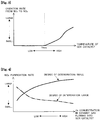
- FIG. 4 is a diagram illustrating correlations between the O 2 concentration in exhaust gas flowing into the SCR catalyst and the NO X purification rate of the SCR catalyst in a case where reducing agent is added through the reducing agent addition valve 5 in a state where the temperature of the SCR catalyst exceeds the predetermined threshold value (Tthre).
- the solid line in FIG. 4 denotes a correlation in a case where the degree of deterioration of the SCR catalyst is comparatively small, while the dashed line in FIG. 4 denotes a correlation in a case where the degree of deterioration of the SCR catalyst is comparatively large. If the degree of deterioration of the SCR catalyst is comparatively small, as denoted by the solid line in FIG.
- the NO X purification rate of the SCR catalyst tends to be higher when the O 2 concentration is higher than when the O 2 concentration is lower. If the degree of deterioration of the SCR catalyst is comparatively large, as denoted by the dashed line in FIG. 4 , the NO X purification rate of the SCR catalyst tends to be higher when the O 2 concentration is low than when the O 2 concentration is high.
- the tendencies depicted in FIG. 4 can conceivably be ascribed to the reasons below.
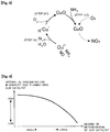
- the SCR catalyst when the SCR catalyst is exposed to an atmosphere at or above a predetermined deterioration start temperature (for instance about 750°C) that is higher than the above predetermined threshold value (Tthre), for instance in a case where the particulate filter of the first catalyst casing 3 has undergone a filter regeneration treatment, copper ions (Cu + ) turn into an oxide (CuO) (step (d')), without being re-oxidized, as illustrated in FIG. 5 , upon contact between the copper ions (Cu + ) having hydrogen ions H + adsorbed thereon with O 2 in the exhaust gas, after the reaction in step (c) above has occurred.
- the oxide (CuO) thus generated remains on the SCR catalyst without reverting to copper ions (Cu + or Cu 2+ ).
- step (a') oxidation reactions from NH 3 to NO X are elicited through supply of NH 3 and O 2 to the above oxide (CuO) (step (a')). That is, when Cu + turns into CuO due to the fact that of the SCR catalyst is exposed to an atmosphere at or above a predetermined deterioration start temperature, reduction reactions of NO X by NH 3 do not occur readily, whereas oxidation reactions from NH 3 to NO X develop readily.
- the greater the amount of oxide (CuO) of copper ions the greater is the degree of deterioration of the SCR catalyst.
- the amount of oxide (CuO) of copper ions trends to increase with increasing duration of the exposure of the SCR catalyst to an atmosphere at or above a predetermined deterioration start temperature.
- the amount of CuO in the SCR catalyst is larger (in the case where a degree of deterioration of the SCR catalyst is large)
- Tthre a predetermined threshold value
- the amount of NH 3 that reacts with O 2 in the exhaust gas in the SCR catalyst increases more readily and accordingly the amount of NO X generated in the SCR catalyst increases more readily as well, as compared with a case where amount of CuO in the SCR catalyst is smaller (in the case where a degree of deterioration of the SCR catalyst is small).
- step (a') of FIG. 4 there increases accordingly the amount of O 2 contributing to oxidation reactions from NH 3 to NO X in step (a') of FIG. 4 described above, since the O 2 concentration in exhaust gas flowing into the SCR catalyst becomes comparatively high when the amount of fuel added through the fuel addition valve 6 is set to be comparatively small at the time of addition of the reducing agent through the reducing agent addition valve 5 in a state where the temperature of the SCR catalyst is higher than a predetermined threshold value. In that case the amount of NO X flowing out of the SCR catalyst may increase due to the increase in the generation amount of NOx derived from NH 3 , and hence the NOx purification rate of the SCR catalyst may drop.
- the amount of NO X reduced by copper ions (Cu 2+ ) in the reference state may decrease on account of smaller amount of copper ions recovered from the lower state to the reference state, and as a result, the NO X purification rate of the SCR catalyst may drop. Therefore, in a case where the degree of deterioration of the SCR catalyst is comparatively small, the NO X purification rate of the SCR catalyst is higher when the O 2 concentration is higher than when the O 2 concentration is lower, whereas in a case where the degree of deterioration of the SCR catalyst is comparatively large, the NO X purification rate of the SCR catalyst is higher when the O 2 concentration is lower than when the O 2 concentration is higher, as in FIG. 4 described above.
- the ECU 10 is set to adjust the amount of fuel added through the fuel addition valve 6 in accordance with the degree of deterioration of the SCR catalyst, in a case where a reducing agent is to be added through the reducing agent addition valve 5 in a state where the temperature of the SCR catalyst exceeds the predetermined threshold value (Tthre).
- the ECU 10 controls the fuel addition valve 6 in such a manner that the amount of fuel added through the fuel addition valve 6 is smaller in a case where the degree of deterioration of the SCR catalyst is smaller than in a case where the degree of deterioration of the SCR catalyst is larger.
- the degree of deterioration of the SCR catalyst is correlated to the time during which the SCR catalyst has been exposed to an atmosphere at or above a predetermined deterioration start temperature.
- the ECU 10 integrates the time during which the SCR catalyst has been exposed at or above a predetermined deterioration start temperature, over the lapse of time since the SCR catalyst was brand new until the present time, and stores the resulting integrated time in a non-volatile memory such as a backup RAM.
- the ECU 10 is set to estimate that the degree of deterioration of the SCR catalyst is larger in a case where integrated time is long than in a case where the integrated time is short.
- the degree of deterioration of the SCR catalyst may be estimated taking into consideration also the atmospheric air-fuel ratio at the time where the SCR catalyst has been exposed to an atmosphere at or above a predetermined deterioration start temperature.
- the degree of deterioration of the SCR catalyst may be estimated to be larger in a case where the integrated value of the time during which the atmospheric air-fuel ratio in the SCR catalyst was a rich air-fuel ratio is long than in a case where the integrated value is short, from within the integrated time during which the SCR catalyst has been exposed to an atmosphere at or above a predetermined deterioration start temperature.
- the ECU 10 determines then the amount of fuel to be added through the fuel addition valve 6 per unit time in accordance with the estimated degree of deterioration of the SCR catalyst. At this time, the ECU 10 determines the amount of fuel to be added through the fuel addition valve 6 per unit time in such a manner that the O 2 concentration in the exhaust gas flowing into the SCR catalyst is lower in a case where the degree of deterioration of the SCR catalyst is larger than in a case where degree of deterioration of the SCR catalyst is smaller, as illustrated in FIG. 6 .
- O 2 concentration deemed to yield the smallest amount of NO X generated through reaction of O 2 in the exhaust gas with NH 3 derived from the reducing agent, in the SCR catalyst, in other words, the O 2 concentration (hereafter also referred to as "optimal O 2 concentration") deemed to afford the highest possible NO X purification rate of the SCR catalyst in a state where the temperature of the SCR catalyst is higher than a predetermined threshold value.
- a correlation between degree of deterioration of the SCR and optimal O 2 concentration, such as that illustrated in FIG. 6 is worked out beforehand on the basis of results of experiments or simulations, and is stored for instance in the ROM of the ECU 10 in the form of a map or a function expression.
- the integrated value of the time during which the SCR catalyst has been exposed to an atmosphere at or above a predetermined deterioration start temperature may be used, instead of the degree of deterioration of the SCR catalyst, as the argument in the map or function expression for determining the optimal O 2 concentration.
- the map or function expression in that case may be constructed in such a manner that the optimal O 2 concentration is lower in a case where the integrated value of the time during which the SCR catalyst has been exposed to an atmosphere at or above a predetermined deterioration start temperature is larger than in a case where the integrated value is smaller.
- the ECU 10 calculates then a fuel addition amount per unit time as necessary in order to bring the O 2 concentration of exhaust gas flowing into the SCR catalyst to the optimal O 2 concentration, on the basis of the amount of exhaust gas discharged per unit time from the internal combustion engine 1 and the O 2 concentration is a well-known feature exhaust gas.
- the amount of exhaust gas discharged per unit time from the internal combustion engine 1 can be calculated on the basis of a value measured by the air flow meter 13 and a fuel injection amount.
- the O 2 concentration in the exhaust gas discharged from the internal combustion engine 1 can be calculated on the basis of a value measured by the air-fuel ratio sensor 15.
- the ECU 10 determines the timing of adding the fuel through the fuel addition valve 6, on the basis of the timing at which the reducing agent is added through the reducing agent addition valve 5.
- the ECU 10 determines a fuel addition timing of the fuel addition valve 6 in such a manner that fuel addition through the fuel addition valve 6 starts earlier than the timing of initiation of addition of reducing agent through the reducing agent addition valve 5. That is because it takes some time (transport delay time) for the exhaust gas having had fuel added thereto through the fuel addition valve 6 to reach the addition position of the reducing agent addition valve 5.
- the ECU 10 firstly calculates the transport delay time on the basis of the flow rate of the exhaust gas.
- the ECU 10 may determine the fuel addition timing of the fuel addition valve 6 in such a manner that fuel addition through the fuel addition valve 6 starts at a timing that precedes, by the above transport delay time, the timing at which there starts the addition of reducing agent through the reducing agent addition valve 5.
- the exhaust gas containing the added fuel flows into the oxidation catalyst of the first catalyst casing 3.
- the exhaust gas flowing into the SCR catalyst is a gas containing NH 3 derived from the reducing agent added through the reducing agent addition valve 5, and having had the O 2 concentration lowered down to the optimal O 2 concentration.
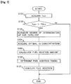
- FIG. 7 is a flowchart illustrating a processing routine that is executed by the ECU 10 during execution of NH 3 oxidation suppression control.
- the processing routine is stored beforehand in the ROM of the ECU 10, and is executed repeatedly at predetermined cycles during the operation of the internal combustion engine 1.
- the ECU 10 firstly acquires the temperature of the SCR catalyst (Tscr), in the process in S101. Specifically, the ECU 10 calculates the temperature of the SCR catalyst (Tscr) on the basis of a value measured by the exhaust gas temperature sensor 9. In a configuration wherein in addition to the above exhaust gas temperature sensor 9, a further exhaust gas temperature sensor is attached also at the exhaust passage 2 between the first catalyst casing 3 and the second catalyst casing 4, the ECU 10 may calculate the temperature of the SCR catalyst (Tscr) on the basis of a difference between values measured by these two exhaust gas temperature sensors.
- the ECU 10 determines whether or not the temperature of the SCR catalyst (Tscr) acquired in the process of S101 is higher than the predetermined threshold value (Tthre). If the temperature of the SCR catalyst (Tscr) is equal to or lower than the predetermined threshold value (Tthre), NH 3 oxidation suppression control need not be carried out, and accordingly the ECU 10 terminates execution of the present processing routine. If on the other hand the temperature of the SCR catalyst (Tscr) is higher than the predetermined threshold value (Tthre), it is necessary to perform NH 3 oxidation suppression control, and accordingly the ECU 10 executes the process from S103 onwards.
- the ECU 10 estimates the degree of deterioration of the SCR catalyst.
- the degree of deterioration of the SCR catalyst is correlated to the temperature history of the SCR catalyst (integrated value of the time during which the SCR catalyst has been exposed to an atmosphere at or above a predetermined deterioration start temperature).
- the ECU 10 integrates the time during which the SCR catalyst has been exposed at or above a predetermined deterioration start temperature, over the lapse of time since the SCR catalyst was brand new until the present time, and stores the resulting integrated time in, for example, a backup RAM in the ECU 10.
- the ECU 10 may derive the degree of deterioration of the SCR catalyst by accessing a map or function expression, such as that illustrated in FIG. 8 , using as the argument the integrated time stored in the backup RAM.
- FIG. 8 is a map or function expression denoting a correlation between the above integrated time and the degree of deterioration of the SCR catalyst, the map or function expression being constructed so that the degree of deterioration of the SCR catalyst is larger in a case where the integrated time is long than in a case where the integrated time is short.
- a correlation such as that illustrated in FIG. 8 is worked out beforehand on the basis of for instance results of experiments or simulations.
- the "estimation unit" according to the present invention is realized herein through execution of the process in S103 by the ECU 10.
- the ECU 10 acquires an optimal O 2 concentration on the basis of the degree of deterioration of the SCR catalyst estimated in the process in S103.
- the ECU 10 accesses a map or function expression such as that illustrated in FIG. 6 described above, using as the argument the degree of deterioration of the SCR catalyst having been estimated in the process in S103, to derive an O 2 concentration (optimal O 2 concentration) that allows raising as much as possible the NOx purification rate of the SCR catalyst.
- the optimal O 2 concentration thus derived is higher in a case where the degree of deterioration of the SCR catalyst is smaller than in a case where the degree of deterioration is larger.
- the ECU 10 calculates a fuel amount (fuel addition amount) that is to be added per unit time through the reducing agent addition valve 5, on the basis of the optimal O 2 concentration acquired in the process in S104. Specifically, the ECU 10 calculates firstly the amount of exhaust gas discharged per unit time from the internal combustion engine 1, on the basis of a value (intake air amount) measured by the air flow meter 13 and a fuel injection amount. The ECU 10 calculates the O 2 concentration in exhaust gas discharged from the internal combustion engine 1 on the basis of a value measured by the air-fuel ratio sensor 15. The ECU 10 calculates the fuel addition amount necessary to lower the O 2 concentration in the exhaust gas down to the optimal O 2 concentration on the basis of the amount of exhaust gas discharged per unit time from the internal combustion engine 1 and the O 2 concentration in the exhaust gas.
- the ECU 10 calculates the timing (fuel addition timing) at which fuel addition through the fuel addition valve 6 is to be initiated. Specifically, the ECU 10 firstly calculates the flow rate of exhaust gas on the basis of the engine rotational speed of the internal combustion engine 1 and a value measured by the air flow meter 13. Next, the ECU 10 calculates a time (transport delay time) necessary for exhaust gas to move from the addition position of the fuel addition valve 6 up to the addition position of the reducing agent addition valve 5, on the basis of the flow rate of the exhaust gas and the distance from the addition position of the fuel addition valve 6 up to the addition position of the reducing agent addition valve 5. The ECU 10 then sets, as the fuel addition timing, a timing that precedes, by the transport delay time, the timing at which addition of the reducing agent through the reducing agent addition valve 5 is to be initiated.
- the ECU 10 adds fuel through the fuel addition valve 6 on the basis of the fuel addition amount calculated in the process in S105 and the fuel addition timing calculated in the process in S106.
- a concentration optimal O 2 concentration
- the O 2 concentration of exhaust gas flowing into the SCR catalyst can be made comparatively low in a case where the degree of deterioration of the SCR catalyst is comparatively large, whereas the O 2 concentration of exhaust gas flowing into the SCR catalyst can be made comparatively high in a case where the degree of deterioration of the SCR catalyst is comparatively small.
- control unit is realized through execution of the process in S103 to S107 by the ECU 10.
- the NO X purification rate of the SCR catalyst can be maximized in a case where the temperature of the SCR catalyst is higher than a predetermined threshold value.
- a predetermined threshold value serving as a reference for determining whether NH 3 oxidation suppression control is to be performed or not is fixed to a value established beforehand, but the predetermined threshold value may be modified in accordance with the degree of deterioration of the SCR catalyst.
- An increase in the amount of copper ions (Cu + ) that turn into an oxide (CuO) may give rise, when the degree of deterioration of the SCR catalyst is larger, to the development of oxidation reactions from NH 3 to NO X elicited through the action of CuO at a temperature region that is lower than when the degree of deterioration of the SCR catalyst is smaller (when the amount of CuO is small). Accordingly, establishing a predetermined threshold value taking into consideration the degree of deterioration of the SCR catalyst allows suppressing more reliably oxidation reactions from NH 3 to NO X by CuO, and allows re-oxidation (valence recovery) of copper ions (Cu + ) having descended to the lower state to develop more reliably.
- the predetermined threshold value (Tthre) may be set to a comparatively high temperature in a case where the degree of deterioration of the SCR catalyst at the time of addition of reducing agent through the reducing agent addition valve 5 is comparatively small, as illustrated in FIG. 9 .
- the predetermined threshold value (Tthre) may be set to an increasingly lower temperature as the degree of deterioration increases.
- NH 3 oxidation suppression control is not executed unless the temperature of the SCR catalyst is a comparatively high temperature, in a case where the degree of deterioration of the SCR catalyst is comparatively small.
- NH 3 oxidation suppression control is executed more reliably in a state where oxidation reactions from NH 3 to NOx mediated by CuO can develop, and accordingly the amount of O 2 contributing to oxidation reactions from NH 3 to NO mediated by CuO can be reduced more reliably. It becomes therefore possible to suppress more reliably oxidation reactions from NH 3 to NO X by CuO.
- a correlation between the degree of deterioration of the SCR and the predetermined threshold value (Tthre), such as that illustrated in FIG. 9 is worked out beforehand on the basis of results of experiments or simulations, and is stored for instance in the ROM of the ECU 10, in the form of a map or a function expression.
- FIG. 10 is a flowchart illustrating a processing routine that is executed by the ECU 10 during execution of NH 3 oxidation suppression control.
- process steps identical to those of the processing routine illustrated in FIG. 7 described above will be denoted with identical reference symbols.
- the ECU 10 executes the processes in S201 to S202 prior to execution of the process in S101. Firstly, in the process in S201, the ECU 10 estimates the degree of deterioration of the SCR catalyst. The same method as in the process in S103 in the processing routine illustrated in FIG. 7 described above can be resorted to as the method for estimating the degree of deterioration of the SCR catalyst.
- the ECU 10 sets a predetermined threshold value (Tthre) on the basis of the degree of deterioration of the SCR catalyst estimated in the process in S201. Specifically, the ECU 10 accesses a map or function expression such as that illustrated in FIG. 9 described above, using as the argument the degree of deterioration of the SCR catalyst having been estimated in the process in S201, to derive a predetermined threshold value (Tthre) suitable for the degree of deterioration of the SCR catalyst.
- the "setting unit" according to the present invention is realized through execution of the process in S202 by the ECU 10.
- the ECU 10 executes sequentially the processes in S101 and S102.
- the predetermined threshold value (Tthre) having been derived and set in the process in S202.
- the ECU 10 executes the process in S104 onwards, instead of executing the process in S103.
- modification of the predetermined threshold value (Tthre) depending on the degree of deterioration of the SCR catalyst allows suppressing more reliably oxidation reactions from NH 3 to NO X by CuO, and allows re-oxidation (valence recovery) of copper ions (Cu + ) having descended to the lower state to take place more reliably.
- the NOx purification rate of the SCR catalyst can be in increased more reliably.
- the present invention can also be used in configurations where a NO X storage reduction (NSR) catalyst alone is accommodated in the first catalyst casing, or a configuration wherein an NSR catalyst and a particulate filter are accommodated in the first catalyst casing.
- NSR NO X storage reduction
- the SCR catalyst may possibly be exposed at or above a predetermined deterioration start temperature, during execution of a treatment (S regeneration treatment) for eliminating sulfur poisoning in the NSR catalyst.
Landscapes
- Engineering & Computer Science (AREA)
- Chemical & Material Sciences (AREA)
- Chemical Kinetics & Catalysis (AREA)
- Combustion & Propulsion (AREA)
- Mechanical Engineering (AREA)
- General Engineering & Computer Science (AREA)
- Health & Medical Sciences (AREA)
- Toxicology (AREA)
- Materials Engineering (AREA)
- Biomedical Technology (AREA)
- Environmental & Geological Engineering (AREA)
- Analytical Chemistry (AREA)
- General Chemical & Material Sciences (AREA)
- Oil, Petroleum & Natural Gas (AREA)
- Exhaust Gas After Treatment (AREA)
- Exhaust Gas Treatment By Means Of Catalyst (AREA)
Applications Claiming Priority (1)
| Application Number | Priority Date | Filing Date | Title |
|---|---|---|---|
| JP2018037556A JP2019152137A (ja) | 2018-03-02 | 2018-03-02 | 内燃機関の排気浄化装置 |
Publications (1)
| Publication Number | Publication Date |
|---|---|
| EP3533979A1 true EP3533979A1 (de) | 2019-09-04 |
Family
ID=65685173
Family Applications (1)
| Application Number | Title | Priority Date | Filing Date |
|---|---|---|---|
| EP19160372.9A Withdrawn EP3533979A1 (de) | 2018-03-02 | 2019-03-01 | Abgasreinigungsvorrichtung für verbrennungsmotor |
Country Status (6)
| Country | Link |
|---|---|
| US (1) | US10487713B2 (de) |
| EP (1) | EP3533979A1 (de) |
| JP (1) | JP2019152137A (de) |
| KR (1) | KR20190104908A (de) |
| CN (1) | CN110219722A (de) |
| BR (1) | BR102019004170A2 (de) |
Families Citing this family (5)
| Publication number | Priority date | Publication date | Assignee | Title |
|---|---|---|---|---|
| JP6627839B2 (ja) * | 2017-10-05 | 2020-01-08 | マツダ株式会社 | エンジンの排気浄化制御装置 |
| DE102017010825B4 (de) * | 2017-11-23 | 2025-11-13 | Mercedes-Benz Group AG | Verfahren zum Betreiben einer Abgasanlage mit einem ersten SCR-Katalysator und einem zweiten SCR-Katalysator |
| JP7406392B2 (ja) * | 2020-02-14 | 2023-12-27 | 株式会社Subaru | 排気ガス浄化装置 |
| BR112022018135B1 (pt) * | 2020-03-12 | 2024-04-30 | Cummins Emission Solutions Inc | Controlador para controlar operação de um sistema de póstratamento e método para um controlador para controlar operação de um sistema de pós-tratamento |
| US11428144B2 (en) * | 2020-10-26 | 2022-08-30 | Ford Global Technologies, Llc | Engine emmissions control methods and systems |
Citations (7)
| Publication number | Priority date | Publication date | Assignee | Title |
|---|---|---|---|---|
| JP2006242094A (ja) * | 2005-03-03 | 2006-09-14 | Hino Motors Ltd | 排気浄化装置 |
| DE102012222603A1 (de) * | 2011-12-12 | 2013-06-13 | Toyota Jidosha Kabushiki Kaisha | Emissionsregelungssystem eines verbrennungsmotors |
| JP2015101968A (ja) | 2013-11-21 | 2015-06-04 | トヨタ自動車株式会社 | 内燃機関の排気浄化装置 |
| EP3064729A1 (de) * | 2015-03-04 | 2016-09-07 | Toyota Jidosha Kabushiki Kaisha | Abgassteuerungssystem für einen verbrennungsmotor |
| US20160363024A1 (en) * | 2014-02-21 | 2016-12-15 | Toyota Jidosha Kabushiki Kaisha | SELECTIVE NOx REDUCTION CATALYST |
| DE102016217126A1 (de) * | 2015-09-11 | 2017-03-16 | Toyota Jidosha Kabushiki Kaisha | Abgasreinigungssystem für Verbrennungsmotor |
| EP3237731A1 (de) * | 2014-12-24 | 2017-11-01 | Toyota Jidosha Kabushiki Kaisha | Abgasreinigungssystem für einen verbrennungsmotor |
Family Cites Families (6)
| Publication number | Priority date | Publication date | Assignee | Title |
|---|---|---|---|---|
| JP3496496B2 (ja) * | 1998-01-08 | 2004-02-09 | 日産自動車株式会社 | 内燃機関の排気浄化装置 |
| US6408616B1 (en) * | 2000-07-20 | 2002-06-25 | Ford Global Technologies, Inc. | Diesel OBD-II system for detection of degradation of catalyst activity |
| JP4118784B2 (ja) * | 2003-10-30 | 2008-07-16 | 本田技研工業株式会社 | 排気ガス浄化装置の劣化診断装置 |
| WO2009082035A1 (ja) * | 2007-12-26 | 2009-07-02 | Toyota Jidosha Kabushiki Kaisha | 内燃機関の排気浄化装置 |
| JP5880705B2 (ja) * | 2012-06-22 | 2016-03-09 | トヨタ自動車株式会社 | 排気浄化装置の劣化検出システム |
| JP6369421B2 (ja) | 2015-08-21 | 2018-08-08 | トヨタ自動車株式会社 | 内燃機関の排気浄化装置 |
-
2018
- 2018-03-02 JP JP2018037556A patent/JP2019152137A/ja active Pending
-
2019
- 2019-02-28 CN CN201910178983.0A patent/CN110219722A/zh active Pending
- 2019-02-28 KR KR1020190023898A patent/KR20190104908A/ko not_active Withdrawn
- 2019-02-28 BR BR102019004170-6A patent/BR102019004170A2/pt not_active IP Right Cessation
- 2019-03-01 EP EP19160372.9A patent/EP3533979A1/de not_active Withdrawn
- 2019-03-01 US US16/290,793 patent/US10487713B2/en not_active Expired - Fee Related
Patent Citations (7)
| Publication number | Priority date | Publication date | Assignee | Title |
|---|---|---|---|---|
| JP2006242094A (ja) * | 2005-03-03 | 2006-09-14 | Hino Motors Ltd | 排気浄化装置 |
| DE102012222603A1 (de) * | 2011-12-12 | 2013-06-13 | Toyota Jidosha Kabushiki Kaisha | Emissionsregelungssystem eines verbrennungsmotors |
| JP2015101968A (ja) | 2013-11-21 | 2015-06-04 | トヨタ自動車株式会社 | 内燃機関の排気浄化装置 |
| US20160363024A1 (en) * | 2014-02-21 | 2016-12-15 | Toyota Jidosha Kabushiki Kaisha | SELECTIVE NOx REDUCTION CATALYST |
| EP3237731A1 (de) * | 2014-12-24 | 2017-11-01 | Toyota Jidosha Kabushiki Kaisha | Abgasreinigungssystem für einen verbrennungsmotor |
| EP3064729A1 (de) * | 2015-03-04 | 2016-09-07 | Toyota Jidosha Kabushiki Kaisha | Abgassteuerungssystem für einen verbrennungsmotor |
| DE102016217126A1 (de) * | 2015-09-11 | 2017-03-16 | Toyota Jidosha Kabushiki Kaisha | Abgasreinigungssystem für Verbrennungsmotor |
Also Published As
| Publication number | Publication date |
|---|---|
| US20190271248A1 (en) | 2019-09-05 |
| KR20190104908A (ko) | 2019-09-11 |
| US10487713B2 (en) | 2019-11-26 |
| JP2019152137A (ja) | 2019-09-12 |
| BR102019004170A2 (pt) | 2019-09-17 |
| CN110219722A (zh) | 2019-09-10 |
Similar Documents
| Publication | Publication Date | Title |
|---|---|---|
| US10487713B2 (en) | Exhaust gas purification apparatus for internal combustion engine | |
| CN101617109B (zh) | 排气后处理系统(eats) | |
| CN104769244B (zh) | 内燃机的排气净化装置 | |
| KR101967559B1 (ko) | 내연 기관의 배기 정화 장치 | |
| CN108625953B (zh) | 内燃机的排气净化装置 | |
| CN101874149A (zh) | 废气净化系统及废气净化方法 | |
| CN107304699A (zh) | 排气净化装置的控制装置 | |
| JP5850166B2 (ja) | 内燃機関の排気浄化システム | |
| CN105765186B (zh) | 内燃机的排气净化装置 | |
| JP6015753B2 (ja) | 内燃機関の排気浄化装置 | |
| JP6112093B2 (ja) | 排気浄化システム | |
| JP2016102424A (ja) | 内燃機関の排気浄化システム | |
| JP2010196496A (ja) | 排気浄化装置 | |
| JP4729990B2 (ja) | 内燃機関の排気浄化装置 | |
| JP2018193867A (ja) | 内燃機関の排気浄化装置 |
Legal Events
| Date | Code | Title | Description |
|---|---|---|---|
| PUAI | Public reference made under article 153(3) epc to a published international application that has entered the european phase |
Free format text: ORIGINAL CODE: 0009012 |
|
| STAA | Information on the status of an ep patent application or granted ep patent |
Free format text: STATUS: REQUEST FOR EXAMINATION WAS MADE |
|
| 17P | Request for examination filed |
Effective date: 20190301 |
|
| AK | Designated contracting states |
Kind code of ref document: A1 Designated state(s): AL AT BE BG CH CY CZ DE DK EE ES FI FR GB GR HR HU IE IS IT LI LT LU LV MC MK MT NL NO PL PT RO RS SE SI SK SM TR |
|
| AX | Request for extension of the european patent |
Extension state: BA ME |
|
| STAA | Information on the status of an ep patent application or granted ep patent |
Free format text: STATUS: THE APPLICATION HAS BEEN WITHDRAWN |
|
| 18W | Application withdrawn |
Effective date: 20191030 |