EP3533215B1 - Lesegerät - Google Patents
Lesegerät Download PDFInfo
- Publication number
- EP3533215B1 EP3533215B1 EP17832735.9A EP17832735A EP3533215B1 EP 3533215 B1 EP3533215 B1 EP 3533215B1 EP 17832735 A EP17832735 A EP 17832735A EP 3533215 B1 EP3533215 B1 EP 3533215B1
- Authority
- EP
- European Patent Office
- Prior art keywords
- support
- reading device
- reading
- text
- image
- Prior art date
- Legal status (The legal status is an assumption and is not a legal conclusion. Google has not performed a legal analysis and makes no representation as to the accuracy of the status listed.)
- Active
Links
- 239000000463 material Substances 0.000 claims description 25
- 230000001771 impaired effect Effects 0.000 claims description 3
- 230000001681 protective effect Effects 0.000 description 6
- 239000011521 glass Substances 0.000 description 4
- 238000001514 detection method Methods 0.000 description 3
- 238000010276 construction Methods 0.000 description 1
- 238000011161 development Methods 0.000 description 1
- 230000018109 developmental process Effects 0.000 description 1
- 238000004806 packaging method and process Methods 0.000 description 1
Images


Classifications
-
- G—PHYSICS
- G09—EDUCATION; CRYPTOGRAPHY; DISPLAY; ADVERTISING; SEALS
- G09B—EDUCATIONAL OR DEMONSTRATION APPLIANCES; APPLIANCES FOR TEACHING, OR COMMUNICATING WITH, THE BLIND, DEAF OR MUTE; MODELS; PLANETARIA; GLOBES; MAPS; DIAGRAMS
- G09B21/00—Teaching, or communicating with, the blind, deaf or mute
- G09B21/001—Teaching or communicating with blind persons
- G09B21/003—Teaching or communicating with blind persons using tactile presentation of the information, e.g. Braille displays
-
- H—ELECTRICITY
- H04—ELECTRIC COMMUNICATION TECHNIQUE
- H04N—PICTORIAL COMMUNICATION, e.g. TELEVISION
- H04N1/00—Scanning, transmission or reproduction of documents or the like, e.g. facsimile transmission; Details thereof
- H04N1/04—Scanning arrangements, i.e. arrangements for the displacement of active reading or reproducing elements relative to the original or reproducing medium, or vice versa
-
- G—PHYSICS
- G09—EDUCATION; CRYPTOGRAPHY; DISPLAY; ADVERTISING; SEALS
- G09B—EDUCATIONAL OR DEMONSTRATION APPLIANCES; APPLIANCES FOR TEACHING, OR COMMUNICATING WITH, THE BLIND, DEAF OR MUTE; MODELS; PLANETARIA; GLOBES; MAPS; DIAGRAMS
- G09B21/00—Teaching, or communicating with, the blind, deaf or mute
- G09B21/001—Teaching or communicating with blind persons
- G09B21/007—Teaching or communicating with blind persons using both tactile and audible presentation of the information
-
- H—ELECTRICITY
- H04—ELECTRIC COMMUNICATION TECHNIQUE
- H04N—PICTORIAL COMMUNICATION, e.g. TELEVISION
- H04N1/00—Scanning, transmission or reproduction of documents or the like, e.g. facsimile transmission; Details thereof
- H04N1/00127—Connection or combination of a still picture apparatus with another apparatus, e.g. for storage, processing or transmission of still picture signals or of information associated with a still picture
- H04N1/00249—Connection or combination of a still picture apparatus with another apparatus, e.g. for storage, processing or transmission of still picture signals or of information associated with a still picture with a photographic apparatus, e.g. a photographic printer or a projector
- H04N1/00267—Connection or combination of a still picture apparatus with another apparatus, e.g. for storage, processing or transmission of still picture signals or of information associated with a still picture with a photographic apparatus, e.g. a photographic printer or a projector with a viewing or projecting apparatus, e.g. for reading image information from a film
-
- H—ELECTRICITY
- H04—ELECTRIC COMMUNICATION TECHNIQUE
- H04N—PICTORIAL COMMUNICATION, e.g. TELEVISION
- H04N2201/00—Indexing scheme relating to scanning, transmission or reproduction of documents or the like, and to details thereof
- H04N2201/04—Scanning arrangements
- H04N2201/0402—Arrangements not specific to a particular one of the scanning methods covered by groups H04N1/04 - H04N1/207
- H04N2201/0434—Arrangements not specific to a particular one of the scanning methods covered by groups H04N1/04 - H04N1/207 specially adapted for scanning pages of a book
Definitions
- the invention relates to a reading device, in particular for the visually impaired, with a flat and transparent support for a reading material and an image recording device for detecting a text and / or an image of at least part of the reading material through the support.
- Readers of the type mentioned are known from practice and exist in different embodiments.
- reading devices are known in which the image recording device has a scanner and the support is formed by a glass plate.
- reading devices are known in which the image recording device has a camera that detects reading material positioned on the support.
- a reader in which the transparent support is realized by a glass plate inclined to a base element.
- a reading material for example a book
- a reading device can be positioned on the support in the known reading device in such a way that a perfect image capture of a text is also possible in edge areas and fold areas of a book or a magazine.
- an image is captured by a camera arranged in the base element through the support.
- the basic element has a base for securely positioning the reader on a surface, for example a table.
- the problem with the known reading device is that it is ultimately designed as a standing device for a fixedly defined location and operating location. A change of location requires considerable transport and, if necessary, packaging. Furthermore, the known reader takes up a very considerable volume of space when not in use, which is particularly troublesome in a living area.
- the present invention is therefore based on the object of designing and developing a reading device of the type mentioned at the outset in such a way that particularly simple transport and simple stowage of the reading device when the reading device is not in use are made possible with structurally simple means.
- the above object is achieved by a reading device with the features of claim 1.
- the reading device is then designed and developed in such a way that the support is assigned a support element which can be pivoted relative to the support about a pivot axis, the support element for positioning the support in an operating position inclined at a definable angle to a vertical direction and in a transport or rest position is pivotable with the support and support element lying essentially against one another.
- the support element for positioning the support can be pivoted into an operating position inclined at a definable angle to a vertical direction and - alternatively - into a transport or rest position different from the operating position, in which the support and the support element lie essentially against one another or on top of each other ,
- the support and the support element can be in the transport or rest position, at least in regions, directly adjacent to one another or can be arranged with a further component in between.
- the pivoting of the support element relative to the support leads to an arrangement in the operating position in which the support element supports the support in the inclined operating position.
- the inclined operating position offers the advantage that, for example, a book or a magazine can be placed on the support in such a way that a book or magazine page also lies flat on the support in the fold area.
- This essentially full-surface planting of the reading material on the Edition ensures a secure and complete acquisition of a text and / or an image of the reading material by the image recording device using, for example, a camera.
- the support element is then simply pivoted out of its pivot position supporting the support in such a way that the support and the support element essentially lie against one another. This results in a collapsed arrangement of the support and the support element.
- This arrangement ensures easy transport and easy storage of the reader when not in use. In a simple case, this arrangement can, for example, be put in a pocket and transported to any other place of use, or, for example, can be stowed in a shelf or in a drawer.
- the reading device according to the invention thus enables particularly simple transport and simple stowing of the reading device when the reading device is not in use with structurally simple means.
- the pivot axis can be implemented in or on the support, preferably in or on an edge region of the support.
- the support element and the support are pivotally mounted on one another. In the operating position, the support and the support element are pivoted at an angle to one another which enables the support to be set up on a surface, the support thereby being able to be positioned in an operating position inclined to a vertical direction.
- the transport or rest position is achieved by pivoting the support and the support element relative to one another, the pivoting taking place until the support and the support element lie essentially on one another or on top of one another.
- the support element or the support can be pivoted to a base element.
- a base element Such an additional component in the form of the base element - in addition to the support element and the support - ensures an increase in the stability of the reading device both in the operating position and in the transport or rest position.
- the basic element can be used as a base serve for the support element and the support.
- the reader In the transport or rest position, the reader can be folded up in such a way that the support element, the support and the base element can lie against one another in a suitable order in order to provide a compact and flat arrangement that is easy to transport or stow away.
- the support element pivotably articulated on the base element or the support pivotally articulated on the base element forms an intermediate component arranged between the base element and the support or between the base element and the support element.
- the pivot axis can be implemented in or on a base element.
- the support element can be pivoted in a suitable manner relative to the base element in order to support the support in the operating position in a suitable manner.
- the basic element can in turn serve as a support for the reader on a surface.
- the support can be realized as a separate component, which stands in a suitable manner on the base element - preferably in a groove or on a projection - and is supported in an inclined position by the support element.
- the support can also be pivotably mounted on the base element.
- both the support element and the support can be pivoted relative to the base element from a position that is essentially one against the other or one on top of the other, in order to achieve the operating position of the support supported by the support element.
- both the support and the support element can in turn be pivoted toward the base element, so that an arrangement of base element, support element and support lying on or on top of one another is formed.
- the support can have a contact area for the support element, the contact area in a particularly advantageous manner being a groove or a Can have projection with which the support element can engage in the operating position.
- the surface can be assigned a preferably flat cover.
- a cover can be placed on a reading material positioned on the support, on the one hand to securely position the reading material on the support and on the other hand to prevent or at least largely reduce the light shining through in the case of a non-light-tight reading material.
- the cover can be pivotable relative to the support.
- the cover can be pivoted on a base element of the reader, so that the cover in the transport or rest position can also be placed on the support, the support element or the base element.
- the reading device can have a processing device for processing the text and / or image captured by the image recording device.
- a processing device can be formed, for example, by a computing unit assigned to the supporting element or the basic element or integrated in the supporting element or in the basic element.
- the reading device can have a display device for displaying the text and / or image processed by the processing device.
- a display device can advantageously be implemented as a common component with a cover. This results in a particularly compact design of the reading device.
- a display device can be implemented, for example, by a screen.
- the reading device can have a voice output device for audio output by means of the processing device have processed text and / or image and / or a Braille display for outputting the text and / or image processed by the processing device in Braille.
- a voice output device can be assigned to the processing device or integrated into the processing device and can have, for example, a loudspeaker or an interface for connecting a loudspeaker, for example headphones.
- a reading device can be provided by assigning a voice output device to the reading device or integrating a voice output device into the reading device.
- the image recording device can have an interface for connecting a processing device for processing the text and / or image captured by the image recording device.
- a processing device for processing the text and / or image captured by the image recording device.
- Such an interface can establish a connection to a computer, for example a PC or laptop.
- the processing device is implemented by the computer, it being possible for the image recording device, for example camera, to be supplied with power via the interface.
- Such a reading device provides a mobile image recording unit with a book edge or magazine edge, which is suitable for the blind and the visually impaired, as well as for every user of a computer in the remaining market.
- the interface can be used to connect a display device for displaying the text and / or image processed by the processing device and / or to connect a voice output device for audio output of the text and / or image processed by the processing device and / or to connect a Braille display for outputting the text and / or image processed by means of or a processing device in Braille.
- a particularly mobile image recording unit for connecting different functional units can be provided by a reading device designed in this way.
- the image recording device can be assigned to the support element, the basic element or the processing device or preferably be integrally coupled to the support element, the base element or the processing device.
- the image recording device it is essential that in the operating position it enables reliable detection of a text and / or an image of at least part of the reading material through the support. Therefore, no further functional elements should be arranged between the image recording device in the form of, for example, a camera and the support. A "clear view" of the camera on the support is desirable.
- the image recording device can be assigned to the support element, for example, or can be coupled to the support element in such a way that the image recording device pivots with the support element when the support element is pivoted relative to the support.
- the image recording device could be integrated into the pivot axis of the support element in a further advantageous manner and to implement a particularly compact configuration of the reading device.
- the reading device In the operating position of the reading device, in which the support and the support element are pivoted and inclined in a suitable manner to one another, a lateral incidence of external light can occur on the image recording device, which impairs reliable detection of a text and / or an image of the reading material.
- the reading device can have at least one protective element, preferably a flap, which can be triangular and / or can be folded out of or from the base element or support element.
- the side areas or side openings of the arrangement of support and support element can be closed at least in certain areas in the operating position, so that incidence of external light from the side can be prevented or at least reduced.
- the at least one protective element can be assigned to the base element or the support element, wherein the at least one protective element can preferably be pivotably mounted on the base element or support element.
- two protective elements are provided, which can be arranged in the operating position on both sides of the arrangement of support and support element.
- a basic element as described above can specifically be designed in the form of a floor pan into which the support element and the support can be pivoted in the transport or rest position.
- Protective elements pivotally mounted on, for example, the base element or the base trough can be folded out of such a base trough and serve to produce an essentially closed body made of protective elements, support, support element and optionally base element.
- a particularly reliable detection of a text and / or an image is ensured here by means of the image recording device.
- the reading device offers numerous advantages.
- a camera-based image recording device ensures that text and / or an image is captured very quickly.
- the arrangement of the reading material on the support which is preferably realized in the form of a glass plate, enables a well-defined environment for the image recording.
- a lighting device for illuminating the reading material can be associated with the support in a further advantageous manner.
- a flat design of the support ensures a secure positioning of the reading material to be recorded.
- the upper edge generated by the inclined positioning of the support serves in a particularly advantageous manner for recognizing and reading the reading material, for example into a fold of books or magazines.
- the reading device in particular the image recording device and / or a processing device and / or a display device and / or a voice output device, can be operated by means of an accumulator - independently of the network.
- an accumulator can be integrated, for example, in the image recording device or in the processing device.
- a processing device suitably assigned to the reading device or integrated in the reading device ensures integrated character recognition and preferably voice output.
- a display device in the form of, for example, a screen can optionally be assigned to the reading device or integrated into the reading device.
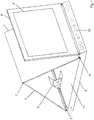
- Fig. 1 shows a schematic and perspective illustration of a first embodiment of the reading device according to the invention with a flat and transparent support 1 in the form of a glass plate for a reading material and an image recording device 2 in the form of a camera for detecting a text and / or an image of at least part of the reading material the edition 1 through.
- the support 1 is assigned a support element 4 which can be pivoted relative to the support 1 about a pivot axis 3.
- the support element 4 is pivotally mounted on the pivot element 3 on a base element 5, which serves as a base or stand for positioning on a surface.
- the support 1 is also pivotably mounted on the base element 5 via a pivot axis 6, so that the support 1 and the support element 4 can be pivoted independently of one another relative to the base element and relative to one another.
- the support element 4 can be pivoted into an operating position inclined at a definable angle to a vertical direction Fig. 1 is shown.
- the vertical direction corresponds to the perpendicular direction and is perpendicular to the earth's surface.
- Both the pivot axis 3 and the pivot axis 6 are realized on the base element 5.
- the support 1 has a contact area in the form of a groove 7 for the support element 4, so that the support element 4 is arranged in the operating position with its upper edge in the groove 7.
- the image recording device 2 is coupled to the support element 4, so that pivoting the support element 4 also results in pivoting the image recording device 2.
- the operating position shown shows the image recording device 2 with its camera on the support 1 on which a reading material to be detected can be positioned.
- the prismatic shape of the reader In its operating position, a flat edition of the reading material, for example a book or a magazine, is guaranteed on the edition 1 up to an edge or fold area of the reading material, so that the complete text and / or image of the reading material is reliably recorded.
- the support 1 is assigned a flat cover 8, which is also pivotally mounted on the base element 5.
- the cover can be used to press or apply the reading material to the edition 1.
- a display device 9 in the form of a screen for displaying the captured text and / or image is integrated in the cover 8. Instead of the cover 8, only a display device 9 can be provided, which can be mounted on the base element 5.
- Control elements 10 for the reading device are implemented on the front of the basic element 5.
- the reading device also has a processing device 11 for processing the text and / or image captured by means of the image recording device 2.
- the processing device 11 is integrated into the basic element 5.
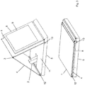
- Fig. 2 shows the execution example Fig. 1 in a folded transport or rest position, the support 1 and the support element 4 essentially lying on one another or on top of one another with the cover 8 in between.
- the support 1 and the support element 4 in the transport or rest position can lie directly and directly or with an element in between.
- this transport or rest position a handy arrangement is realized which can be transported in a simple manner, for example in a pocket or gripped with only one hand.
- Fig. 3 shows in two schematic and perspective representations a second embodiment of the reading device according to the invention in an operating position and in a transport or rest position.
- the Pad 1 can be pivoted relative to support element 4 via a pivot axis 3, which is realized in an edge region of pad 1.
- the support 1 and the support element 4 are directly coupled to one another via the pivot axis 3.
- the support element 4 is pivotally mounted on the base element 5 on the side facing away from the support 1 via a further pivot axis 12.
- the support 1 In the operating position, the support 1 is supported in a groove 13 formed in the base element 5.
- the processing device 11 is also arranged in the basic element 5 in this exemplary embodiment.
- the transport or rest position shown below is first placed on the cover 8 on the base element 5 and thereupon the support element 4 and the support 1 - pivoted away from the base element 5 - are placed on the cover 8 in the folded state.
- the support 1 can be pivotably mounted on the base element 5, in which case the support element 4 can be supported in a groove formed in the base element 5 in order to provide the prism-like operating position.
- Fig. 4 shows a third embodiment of the reading device according to the invention in two schematic and perspective representations.
- no base element is provided and the support 1 and the support element 4 are pivotally mounted directly on one another.
- the pad 1 is assigned a cover 8 which can be pivoted to the pad 1.
- a display device 9 is pivotally mounted on the support element 4.
- a processing device 11 for processing the text and / or image captured by the image recording device 2 is also assigned to the support element 4.
- the image recording device 2 is in Fig. 4 not shown and is essentially assigned to the processing device 11 or integrated into it.
- the third embodiment is shown in a transport or rest position.
- Fig. 5 shows a schematic and perspective view of a fourth embodiment of the reading device according to the invention in its operating position. Like that in Fig. 4 The third exemplary embodiment shown also has the in Fig. 5 shown fourth embodiment no basic element.
- the support 1 is mounted relative to the support element 4 via a pivot axis 3.
- a processing device 11 with an integrated image recording device 2 (not shown here) is assigned to the support element 4.
- a cover 8 with an integrated display device 9 is pivotally mounted on the support 1 on the support 1.
- a support 14 is assigned to the cover 8 or the display device 9 and is pivotably mounted on the cover 8 or the display device 9. As a result, the inclination of the display device 9 can be predetermined during operation of the reading device, wherein the support 14 can be supported on the support 1.
- Fig. 6 shows a fifth embodiment of the reading device according to the invention, this embodiment having a support 1, a support element 4 and a base element 5 designed as a floor pan. Both the support 1 and the support element 4 are pivotally mounted on the base element 5.
- the support element 4 is supported on the base element 5 via a pivot axis 3 and the support 1 is supported on the base element 5 via a further pivot axis, not shown here.
- the cover 8 is also pivotally mounted on the base element 5.
- the edition 1 could as in Fig. 3
- the second exemplary embodiment shown can be pivotably mounted on the support element 4 instead of on the base element 5, the support element 4 also being pivotably mounted on the base element 5.
- the support 1 could be pivotably mounted on the base element 5 and the support element 4 on the support 1 and not on the base element 5.
- Embodiment shown and the alternative embodiments to this embodiment mentioned in the last paragraph is essential that this reader does not have a processing device, but only an interface for connecting such a processing device and / or a display device and / or a voice output device.
- the reader according to the embodiment in Fig. 6 and the associated Alternative embodiments mentioned in the last paragraph and not shown essentially consist only of the support 1, the support element 4, the base element 5, the image recording device 2 and a suitable interface, the base element 5 also not being absolutely necessary and in the context of a further exemplary embodiment can be omitted directly on the support element 4 when the support 1 is pivoted.
- the image recording device 2 can be supplied with current via this interface.
- a processing device for processing the text and / or image captured by means of the image recording device 2 can be connected via an interface designed, for example, as a USB connection.
- a mobile image recording unit is provided which can be easily transported to the desired locations. Since this exemplary embodiment has no processing device, display device or voice output device, it is particularly light and mobile. It is also conceivable that a permanently installed or removable memory is assigned to the image recording device 2 in order to store captured text and / or a captured image of a reading material for later processing, for example.
- Fig. 7 shows the embodiment in a schematic and perspective representation Fig. 6 in the transport or rest position.
- the support 1, the support element 4 and the cover 8 are pivoted in a protected manner into the base element 5 designed as a floor pan.
- the support 1 lies on the support element 4 and the support element 4 on the cover 8.
Landscapes
- Engineering & Computer Science (AREA)
- Signal Processing (AREA)
- Multimedia (AREA)
- Educational Administration (AREA)
- Physics & Mathematics (AREA)
- Business, Economics & Management (AREA)
- Health & Medical Sciences (AREA)
- Educational Technology (AREA)
- General Physics & Mathematics (AREA)
- Theoretical Computer Science (AREA)
- General Health & Medical Sciences (AREA)
- Audiology, Speech & Language Pathology (AREA)
- Facsimile Scanning Arrangements (AREA)
- Studio Devices (AREA)
- Facsimiles In General (AREA)
Description
- Die Erfindung betrifft ein Lesegerät, insbesondere für Sehbehinderte, mit einer flächigen und transparenten Auflage für ein Lesegut und einer Bildaufnahmeeinrichtung zur Erfassung eines Texts und/oder eines Bilds zumindest eines Teils des Leseguts durch die Auflage hindurch.
- Lesegeräte der eingangs genannten Art sind aus der Praxis bekannt und existieren in unterschiedlichen Ausführungsformen. Beispielsweise sind Lesegeräte bekannt, bei denen die Bildaufnahmeeinrichtung einen Scanner aufweist und die Auflage durch eine Glasplatte gebildet wird.
- Des Weiteren sind Lesegeräte bekannt, bei denen die Bildaufnahmeeinrichtung eine Kamera aufweist, die auf der Auflage positioniertes Lesegut erfasst.
- Des Weiteren ist aus der
DE 10 2012 221 810 A1 ein Lesegerät bekannt, bei dem die transparente Auflage durch eine zu einem Grundelement geneigte Glasplatte realisiert ist. Ein Lesegut, beispielsweise ein Buch, kann bei dem bekannten Lesegerät derart auf die Auflage positioniert werden, dass eine einwandfreie Bilderfassung eines Texts auch in Randbereichen und Falzbereichen eines Buchs oder einer Zeitschrift möglich ist. Eine Bildaufnahme erfolgt bei dem bekannten Lesegerät durch eine in dem Grundelement angeordnete Kamera durch die Auflage hindurch. Das Grundelement weist eine Standfläche zum sicheren Positionieren des Lesegeräts auf einem Untergrund, beispielsweise einem Tisch, auf. - Bei dem bekannten Lesegerät ist problematisch, dass es letztendlich im Sinne eines Standgeräts für einen fest definierten Stand- und Betriebsort ausgebildet ist. Ein Wechsel des Einsatzorts bedarf eines nicht unbeträchtlichen Transport- und gegebenenfalls Verpackungsaufwands. Des Weiteren nimmt das bekannte Lesegerät bei Nichtbenutzung ein ganz erhebliches Raumvolumen ein, wobei dies insbesondere in einem Wohnbereich störend ist.
- Der vorliegenden Erfindung liegt daher die Aufgabe zugrunde, ein Lesegerät der eingangs genannten Art derart auszugestalten und weiterzubilden, dass ein besonders einfacher Transport und ein einfaches Verstauen des Lesegeräts bei Nichtgebrauch des Lesegeräts mit konstruktiv einfachen Mitteln ermöglicht sind.
- Erfindungsgemäß wird die voranstehende Aufgabe durch ein Lesegerät mit den Merkmalen des Anspruchs 1 gelöst. Danach ist das Lesegerät derart ausgestaltet und weitergebildet, dass der Auflage ein relativ zur Auflage um eine Schwenkachse verschwenkbares Stützelement zugeordnet ist, wobei das Stützelement zum Positionieren der Auflage in eine in einem definierbaren Winkel zu einer vertikalen Richtung geneigte Betriebsstellung und in eine Transport- oder Ruhestellung mit im Wesentlichen aneinander liegenden Auflage und Stützelement verschwenkbar ist.
- In erfindungsgemäßer Weise ist zunächst erkannt worden, dass durch geschickte Anordnung der Auflage die voranstehende Aufgabe auf überraschend einfache Weise gelöst wird. In weiter erfindungsgemäßer Weise ist dann erkannt worden, dass durch die Realisierung eines relativ zur Auflage um eine Schwenkachse verschwenkbaren Stützelements eine Konstruktion bereitgestellt werden kann, die einen besonders einfachen Transport und ein einfaches Verstauen des Lesegeräts bei Nichtgebrauch des Lesegeräts gewährleistet. Dabei ist das Stützelement zum Positionieren der Auflage in eine in einem definierbaren Winkel zu einer vertikalen Richtung geneigte Betriebsstellung und - alternativ hierzu - in eine zu der Betriebsstellung unterschiedliche Transport- oder Ruhestellung verschwenkbar, in der die Auflage und das Stützelement im Wesentlichen aneinander oder aufeinander liegen. Dabei können die Auflage und das Stützelement in der Transport- oder Ruhestellung zumindest bereichsweise direkt aneinander liegen oder mit einem dazwischenliegenden weiteren Bauelement angeordnet werden. Das Verschwenken des Stützelements relativ zu der Auflage führt in der Betriebsstellung zu einer Anordnung, in der das Stützelement die Auflage in der geneigten Betriebsstellung abstützt. Die geneigte Betriebsstellung bietet dabei den Vorteil, dass beispielsweise ein Buch oder eine Zeitschrift so auf die Auflage aufgelegt werden kann, dass eine Buch- oder Zeitschriftenseite auch im Falzbereich flächig an der Auflage zu liegen kommt. Diese im Wesentlichen vollflächige Anlage des Leseguts an der Auflage gewährleistet eine sichere und vollständige Erfassung eines Texts und/oder eines Bilds des Leseguts durch die Bildaufnahmeeinrichtung mittels beispielsweise einer Kamera. Zum Erreichen der Transport- oder Ruhestellung wird das Stützelement dann einfach aus seiner die Auflage stützenden Schwenkposition derart verschwenkt, dass die Auflage und das Stützelement im Wesentlichen aneinander liegen. Hierdurch ist eine zusammengeklappte Anordnung der Auflage und des Stützelements realisiert. Diese Anordnung gewährleistet einen einfachen Transport und ein einfaches Verstauen des Lesegeräts bei Nichtgebrauch. In einem einfachen Fall kann diese Anordnung beispielsweise in eine Tasche gesteckt und an einen beliebigen weiteren Einsatzort transportiert werden oder beispielsweise in einem Regal oder in einer Schublade verstaut werden.
- Das erfindungsgemäße Lesegerät ermöglicht somit einen besonders einfachen Transport und ein einfaches Verstauen des Lesegeräts bei Nichtgebrauch des Lesegeräts mit konstruktiv einfachen Mitteln.
- Im Hinblick auf eine konstruktiv besonders einfache Ausgestaltung kann die Schwenkachse in oder an der Auflage realisiert sein, vorzugsweise in oder an einem Randbereich der Auflage. Bei dieser Ausführungsform sind das Stützelement und die Auflage schwenkbar aneinander gelagert. In der Betriebsstellung sind die Auflage und das Stützelement in einem Winkel zueinander verschwenkt, der ein Aufstellen der Auflage auf einem Untergrund ermöglicht, wobei die Auflage hierdurch in eine zu einer vertikalen Richtung geneigte Betriebsstellung positionierbar ist. Die Transport- oder Ruhestellung wird durch ein Verschwenken der Auflage und des Stützelements relativ zueinander erreicht, wobei das Verschwenken soweit erfolgt, bis die Auflage und das Stützelement im Wesentlichen aneinander oder aufeinander liegen.
- Zur Realisierung einer besonders stabilen Ausführung des erfindungsgemäßen Lesegeräts kann das Stützelement oder die Auflage an einem Grundelement schwenkbar angelenkt sein. Durch ein derartiges zusätzliches Bauteil in Form des Grundelements - zu dem Stützelement und der Auflage - ist eine Erhöhung der Stabilität des Lesegeräts sowohl in der Betriebsstellung als auch in der Transport- oder Ruhestellung gewährleistet. Das Grundelement kann dabei als Standbasis für das Stützelement und die Auflage dienen. In der Transport- oder Ruhestellung ist ein Zusammenklappen des Lesegeräts dahingehend möglich, dass das Stützelement, die Auflage und das Grundelement in geeigneter Reihenfolge aneinander liegen können, um eine kompakte und flache Anordnung bereitzustellen, die einfach zu transportieren oder zu verstauen ist. Bei dieser Ausführung bildet das an dem Grundelement schwenkbar angelenkte Stützelement oder die am Grundelement schwenkbar angelenkte Auflage ein zwischen dem Grundelement und der Auflage beziehungsweise zwischen dem Grundelement und dem Stützelement angeordnetes Zwischenbauteil.
- Bei einer alternativen vorteilhaften Ausgestaltung kann die Schwenkachse in oder an einem Grundelement realisiert sein. Hierbei kann das Stützelement in geeigneter Weise relativ zum Grundelement verschwenkt werden, um die Auflage in der Betriebsstellung in geeigneter Weise abzustützen. Das Grundelement kann hierbei wiederum als Standauflage des Lesegeräts auf einem Untergrund dienen.
- Die Auflage kann als separates Bauteil realisiert sein, das in geeigneter Weise auf dem Grundelement - vorzugsweise in einer Nut oder an einem Vorsprung - aufsteht und in einer geneigten Stellung durch das Stützelement abgestützt wird. In besonders vorteilhafter Weise und zur Realisierung einer in einer Baugruppe gekoppelten Anordnung kann auch die Auflage an dem Grundelement schwenkbar gelagert sein. Zur Bildung der Betriebsstellung können sowohl das Stützelement als auch die Auflage aus einer im Wesentlichen aneinander oder aufeinander liegenden Position relativ zum Grundelement verschwenkt werden, um die durch das Stützelement abgestützte Betriebsstellung der Auflage zu erreichen. Zur Realisierung der Transport- oder Ruhestellung können wiederum sowohl die Auflage als auch das Stützelement zum Grundelement hin verschwenkt werden, so dass eine aneinander oder aufeinander liegende Anordnung aus Grundelement, Stützelement und Auflage gebildet wird.
- Im Hinblick auf eine besonders sichere Positionierung der Auflage in der Betriebsstellung kann die Auflage einen Anlagebereich für das Stützelement aufweisen, wobei der Anlagebereich in besonders vorteilhafter Weise eine Nut oder einen Vorsprung aufweisen kann, mit dem das Stützelement in der Betriebsstellung in Eingriff gelangen kann.
- Zur Gewährleistung einer besonders sicheren Bilderfassung kann der Auflage eine vorzugsweise flächige Abdeckung zugeordnet sein. Eine derartige Abdeckung kann auf ein auf der Auflage positioniertes Lesegut aufgelegt werden, um einerseits das Lesegut sicher auf die Auflage zu positionieren und um andererseits ein Durchscheinen von Licht bei einem nicht lichtdichten Lesegut zu verhindern oder zumindest weitestgehend zu reduzieren.
- In weiter vorteilhafter Weise kann die Abdeckung relativ zu der Auflage verschwenkbar sein. Dabei kann die Abdeckung an einem Grundelement des Lesegeräts verschwenkbar sein, so dass die Abdeckung in der Transport- oder Ruhestellung ebenfalls an die Auflage, das Stützelement oder das Grundelement anlegbar ist. Im Ergebnis kann hierdurch auch bei der zusätzlichen Realisierung einer Abdeckung eine kompakte, zusammengeklappte oder zusammengefaltete Anordnung des Lesegeräts realisiert werden.
- Bei einer konkreten Ausführungsform kann das Lesegerät eine Verarbeitungseinrichtung zum Verarbeiten des mittels der Bildaufnahmeeinrichtung erfassten Texts und/oder Bilds aufweisen. Eine derartige Verarbeitungseinrichtung kann beispielsweise durch eine dem Stützelement oder dem Grundelement zugeordnete oder in das Stützelement oder in das Grundelement integrierte Recheneinheit gebildet sein.
- Bei einer weiteren Ausführungsform kann das Lesegerät eine Anzeigeeinrichtung zur Anzeige des mittels der Verarbeitungseinrichtung verarbeiteten Texts und/oder Bilds aufweisen. Eine derartige Anzeigeeinrichtung kann in vorteilhafter Weise als gemeinsames Bauteil mit einer Abdeckung realisiert sein. Hierdurch ist ein besonders kompakter Aufbau des Lesegeräts realisiert. Eine Anzeigeeinrichtung kann beispielsweise durch einen Bildschirm realisiert sein.
- Alternativ oder zusätzlich zu einer derartigen Anzeigeeinrichtung kann das Lesegerät eine Sprachausgabeeinrichtung zur Audioausgabe des mittels der Verarbeitungseinrichtung verarbeiteten Texts und/oder Bilds und/oder eine Braillezeile zur Ausgabe des mittels der Verarbeitungseinrichtung verarbeiteten Texts und/oder Bilds in Brailleschrift aufweisen. Eine derartige Sprachausgabeeinrichtung kann der Verarbeitungseinrichtung zugeordnet oder in die Verarbeitungseinrichtung integriert sein und beispielsweise einen Lautsprecher oder eine Schnittstelle zum Anschließen eines Lautsprechers, beispielsweise Kopfhörers, aufweisen. Durch die Zuordnung einer Sprachausgabeeinrichtung zu dem Lesegerät oder Integration einer Sprachausgabeeinrichtung in das Lesegerät kann ein Vorlesegerät bereitgestellt werden.
- Bei einem weiteren Ausführungsbeispiel des erfindungsgemäßen Lesegeräts kann die Bildaufnahmeeinrichtung eine Schnittstelle zum Anschließen einer Verarbeitungseinrichtung zum Verarbeiten des mittels der Bildaufnahmeeinrichtung erfassten Texts und/oder Bilds aufweisen. Eine derartige Schnittstelle kann eine Verbindung zu einem Rechner, beispielsweise PC oder Laptop, herstellen. Die Verarbeitungseinrichtung wird dabei durch den Rechner realisiert, wobei eine Stromversorgung der Bildaufnahmeeinrichtung, beispielsweise Kamera, über die Schnittstelle erfolgen kann. Mit einem derartigen Lesegerät ist eine mobile Bildaufnahmeeinheit mit einer Buchkante oder Zeitschriftenkante bereitgestellt, die sowohl für Blinde und Sehbehinderte, als auch im verbleibenden Markt für jeden Nutzer eines Rechners geeignet ist.
- Alternativ oder zusätzlich kann die Schnittstelle zum Anschließen einer Anzeigeeinrichtung zur Anzeige des mittels der oder einer Verarbeitungseinrichtung verarbeiteten Texts und/oder Bilds und/oder zum Anschließen einer Sprachausgabeeinrichtung zur Audioausgabe des mittels der oder einer Verarbeitungseinrichtung verarbeiteten Texts und/oder Bilds und/oder zum Anschließen einer Braillezeile zur Ausgabe des mittels der oder einer Verarbeitungseinrichtung verarbeiteten Texts und/oder Bilds in Brailleschrift ausgebildet sein. In jedem Fall kann durch ein derart ausgebildetes Lesegerät eine besonders mobile Bildaufnahmeeinheit zum Anschluss unterschiedlicher Funktionseinheiten bereitgestellt werden.
- Je nach individuellem Erfordernis kann die Bildaufnahmeeinrichtung dem Stützelement, dem Grundelement oder der Verarbeitungseinrichtung zugeordnet oder mit dem Stützelement, dem Grundelement oder der Verarbeitungseinrichtung vorzugsweise integral gekoppelt sein. Bei der Anordnung oder Zuordnung der Bildaufnahmeeinrichtung ist wesentlich, dass diese in der Betriebsstellung eine sichere Erfassung eines Texts und/oder eines Bilds zumindest eines Teils des Leseguts durch die Auflage hindurch ermöglicht. Zwischen der Bildaufnahmeeinrichtung in Form beispielsweise einer Kamera und der Auflage sollten daher keine weiteren Funktionselemente angeordnet sein. Eine "freie Sicht" der Kamera auf die Auflage ist wünschenswert. Im Konkreten kann die Bildaufnahmeeinrichtung beispielsweise dem Stützelement derart zugeordnet sein oder derart mit dem Stützelement gekoppelt sein, dass die Bildaufnahmeeinrichtung mit dem Stützelement mitschwenkt, wenn das Stützelement relativ zur Auflage verschwenkt wird. Die Bildaufnahmeeinrichtung könnte in weiter vorteilhafter Weise und zur Realisierung einer besonders kompakten Ausgestaltung des Lesegeräts in die Schwenkachse des Stützelements integriert sein.
- In der Betriebsstellung des Lesegeräts, in der die Auflage und das Stützelement in geeigneter Weise zueinander verschwenkt und geneigt sind, kann ein seitlicher Fremdlichteinfall auf die Bildaufnahmeeinrichtung erfolgen, der eine sichere Erfassung eines Texts und/oder eines Bilds des Leseguts beeinträchtigt. Zur Verhinderung oder Reduzierung eines derartigen Fremdlichteinfalls kann das Lesegerät mindestens ein Schutzelement, vorzugsweise eine Klappe, aufweisen, die dreieckig ausgebildet sein kann und/oder aus oder von dem Grundelement oder Stützelement ausklappbar sein kann. Hierdurch können die seitlichen Bereiche oder Seitenöffnungen der Anordnung aus Auflage und Stützelement in der Betriebsstellung zumindest bereichsweise geschlossen werden, so dass ein seitlicher Fremdlichteinfall verhindert oder zumindest reduziert werden kann.
- Bei einer konkreten Ausführungsform kann das mindestens eine Schutzelement dem Grundelement oder dem Stützelement zugeordnet sein, wobei vorzugsweise das mindestens eine Schutzelement schwenkbar an dem Grundelement oder Stützelement gelagert sein kann. In weiter vorteilhafter Weise sind zwei Schutzelemente vorgesehen, die auf beiden Seiten der Anordnung aus Auflage und Stützelement in der Betriebsstellung angeordnet sein können.
- Ein wie oben beschriebenes Grundelement kann im Konkreten in Form einer Bodenwanne ausgebildet sein, in die das Stützelement und die Auflage in der Transport- oder Ruhestellung eingeschwenkt sein können. An beispielsweise dem Grundelement oder der Bodenwanne schwenkbar gelagerte Schutzelemente können aus einer derartigen Bodenwanne herausgeklappt werden und zum Erzeugen eines im Wesentlichen geschlossenen Körpers aus Schutzelementen, Auflage, Stützelement und gegebenenfalls Grundelement dienen. Hierbei ist eine besonders sichere Erfassung eines Texts und/oder eines Bilds mittels der Bildaufnahmeeinrichtung gewährleistet.
- Das erfindungsgemäße Lesegerät bietet zahlreiche Vorteile. Eine kamerabasierte Bildaufnahmeeinrichtung gewährleitet eine sehr schnelle Erfassung eines Texts und/oder eines Bilds. Die Anordnung des Leseguts auf der vorzugsweise in Form einer Glasplatte realisierten Auflage ermöglicht eine wohldefinierte Umgebung für die Bildaufnahme. Der Auflage kann in weiter vorteilhafter Weise eine Beleuchtungseinrichtung zum Beleuchten des Leseguts zugeordnet sein. Eine flache Ausbildung der Auflage gewährleistet eine sichere Positionierung des zu erfassenden Leseguts. Die durch das geneigte Positionieren der Auflage erzeugte obere Kante dient in besonders vorteilhafter Weise zum Erkennen und Lesen des Leseguts bis in beispielsweise einen Falz von Büchern oder Zeitschriften. Durch die Zusammenklappbarkeit des Lesegeräts aufgrund der Verschwenkbarkeit der Auflage und des Stützelements relativ zueinander kann das Lesegerät in eine sehr kleine und portable Anordnung verbracht werden. Das Lesegerät, insbesondere die Bildaufnahmeeinrichtung und/oder eine Verarbeitungseinrichtung und/oder eine Anzeigeeinrichtung und/oder eine Sprachausgabeeinrichtung, kann mittels eines Akkumulators - netzunabhängig - betrieben werden. Ein derartiger Akkumulator kann beispielsweise in die Bildaufnahmeeinrichtung oder in die Verarbeitungseinrichtung integriert werden. Eine dem Lesegerät geeignet zugeordnete oder in das Lesegerät integrierte Verarbeitungseinrichtung gewährleistet eine integrierte Zeichenerkennung und vorzugsweise Sprachausgabe. Eine Anzeigeeinrichtung in Form beispielsweise eines Bildschirms kann optional dem Lesegerät zugeordnet oder in das Lesegerät integriert werden.
- Es gibt nun verschiedene Möglichkeiten, die Lehre der vorliegenden Erfindung in vorteilhafter Weise auszugestalten und weiterzubilden. Dazu ist einerseits auf die nachgeordneten Ansprüche und andererseits auf die nachfolgende Erläuterung bevorzugter Ausführungsbeispiele der Erfindung anhand der Zeichnung zu verweisen. In Verbindung mit der Erläuterung der bevorzugten Ausführungsbeispiele der Erfindung anhand der Zeichnung werden auch im Allgemeinen bevorzugte Ausgestaltungen und Weiterbildungen der Lehre erläutert. In der Zeichnung zeigen
- Fig. 1
- in einer schematischen und perspektivischen Darstellung ein erstes Ausführungsbeispiel des erfindungsgemäßen Lesegeräts,
- Fig. 2
- in einer schematischen und perspektivischen Darstellung das Lesegerät aus
Fig. 1 im zusammengeklappten Zustand, - Fig. 3
- in einer schematischen und perspektivischen Darstellung ein zweites Ausführungsbeispiel des erfindungsgemäßen Lesegeräts in einer Betriebsstellung und in einer zusammengeklappten Transport- oder Ruhestellung,
- Fig. 4
- in einer schematischen und perspektivischen Darstellung ein drittes Ausführungsbeispiel des erfindungsgemäßen Lesegeräts in einer Betriebsstellung und in einer zusammengeklappten Transport- oder Ruhestellung,
- Fig. 5
- in einer schematischen und perspektivischen Darstellung ein viertes Ausführungsbeispiel des erfindungsgemäßen Lesegeräts in einer Betriebsstellung,
- Fig. 6
- in einer schematischen und perspektivischen Darstellung ein fünftes Ausführungsbeispiel des erfindungsgemäßen Lesegeräts in einer Betriebsstellung und
- Fig. 7
- in einer schematischen und perspektivischen Darstellung das Lesegerät aus
Fig. 6 in einer zusammengeklappten Transport- oder Ruhestellung. -
Fig. 1 zeigt in einer schematischen und perspektivischen Darstellung ein erstes Ausführungsbeispiel des erfindungsgemäßen Lesegeräts mit einer flächigen und transparenten Auflage 1 in Form einer Glasplatte für ein Lesegut und einer Bildaufnahmeeinrichtung 2 in Form einer Kamera zur Erfassung eines Texts und/oder eines Bilds zumindest eines Teils des Leseguts durch die Auflage 1 hindurch. Im Hinblick auf einen besonders einfachen Transport und ein einfaches Verstauen des Lesegeräts bei Nichtgebrauch des Lesegeräts ist der Auflage 1 ein relativ zur Auflage 1 um eine Schwenkachse 3 verschwenkbares Stützelement 4 zugeordnet. Im Konkreten ist das Stützelement 4 über die Schwenkachse 3 an einem Grundelement 5 schwenkbar gelagert, das als Aufstellbasis oder Standhilfe zur Positionierung auf einem Untergrund dient. Die Auflage 1 ist über eine Schwenkachse 6 ebenfalls am Grundelement 5 schwenkbar gelagert, so dass die Auflage 1 und das Stützelement 4 unabhängig voneinander relativ zum Grundelement und relativ zueinander verschwenkbar sind. - Das Stützelement 4 ist zum Positionieren der Auflage 1 in eine in einem definierbaren Winkel zu einer vertikalen Richtung geneigte Betriebsstellung verschwenkbar, die in
Fig. 1 gezeigt ist. Die vertikale Richtung entspricht der Lotrichtung und verläuft senkrecht zur Erdoberfläche. Sowohl die Schwenkachse 3 als auch die Schwenkachse 6 sind an dem Grundelement 5 realisiert. Die Auflage 1 weist einen Anlagebereich in Form einer Nut 7 für das Stützelement 4 auf, so dass das Stützelement 4 in der Betriebsstellung mit seinem oberen Rand in der Nut 7 angeordnet ist. - Die Bildaufnahmeeinrichtung 2 ist mit dem Stützelement 4 gekoppelt, so dass ein Verschwenken des Stützelements 4 auch ein Verschwenken der Bildaufnahmeeinrichtung 2 zur Folge hat. In der in
Fig. 1 gezeigten Betriebsstellung zeigt die Bildaufnahmeeinrichtung 2 mit ihrer Kamera auf die Auflage 1, auf der ein zu erfassendes Lesegut positioniert werden kann. Die prismenartige Form des Lesegeräts in seiner Betriebsstellung gewährleistet eine flächige Auflage des Leseguts, beispielsweise ein Buch oder eine Zeitschrift, auf der Auflage 1 bis in einen Rand- oder Falzbereich des Leseguts, so dass eine sichere Erfassung des vollständigen Texts und/oder Bilds des Leseguts ermöglicht ist. - Der Auflage 1 ist eine flächige Abdeckung 8 zugeordnet, die ebenfalls schwenkbar an dem Grundelement 5 gelagert ist. Die Abdeckung kann zum Andrücken oder Anlegen des Leseguts an die Auflage 1 verwendet werden. Des Weiteren ist in die Abdeckung 8 eine Anzeigeeinrichtung 9 in Form eines Bildschirms zur Anzeige des erfassten Texts und/oder Bilds integriert. Anstelle der Abdeckung 8 kann auch ausschließlich eine Anzeigeeinrichtung 9 vorgesehen sein, die an dem Grundelement 5 gelagert sein kann.
- An der Vorderseite des Grundelements 5 sind Bedienelemente 10 für das Lesegerät realisiert.
- Das Lesegerät weist des Weiteren eine Verarbeitungseinrichtung 11 zum Verarbeiten des mittels der Bildaufnahmeeinrichtung 2 erfassten Texts und/oder Bilds auf. Bei dem hier gezeigten Ausführungsbeispiel ist die Verarbeitungseinrichtung 11 in das Grundelement 5 integriert.
-
Fig. 2 zeigt das Ausführungseispiel ausFig. 1 in einer zusammengeklappten Transport- oder Ruhestellung, wobei die Auflage 1 und das Stützelement 4 im Wesentlichen - mit dazwischenliegender Abdeckung 8 - aneinander oder aufeinander liegen. Je nach Ausgestaltung können die Auflage 1 und das Stützelement 4 in der Transport- oder Ruhestellung direkt und unmittelbar oder mit einem dazwischenliegenden Element aneinander liegen. In dieser Transport- oder Ruhestellung ist eine handliche Anordnung realisiert, die auf einfache Weise, beispielsweise in eine Tasche gesteckt oder nur mit einer Hand gegriffen, transportiert werden kann. -
Fig. 3 zeigt in zwei schematischen und perspektivischen Darstellungen ein zweites Ausführungsbeispiel des erfindungsgemäßen Lesegeräts in einer Betriebsstellung und in einer Transport- oder Ruhestellung. Bei diesem Ausführungsbeispiel ist die Auflage 1 relativ zum Stützelement 4 über eine Schwenkachse 3 verschwenkbar, die in einem Randbereich der Auflage 1 realisiert ist. Die Auflage 1 und das Stützelement 4 sind bei dieser Ausgestaltung über die Schwenkachse 3 direkt miteinander gekoppelt. Das Stützelement 4 ist an der der Auflage 1 abgewandten Seite an dem Grundelement 5 über eine weitere Schwenkachse 12 schwenkbar gelagert. - In der Betriebsstellung ist die Auflage 1 in einer in dem Grundelement 5 ausgebildeten Nut 13 abgestützt. Die Verarbeitungseinrichtung 11 ist bei diesem Ausführungsbeispiel ebenfalls in dem Grundelement 5 angeordnet. In der in
Fig. 3 unten dargestellten Transport- oder Ruhestellung ist zunächst die Abdeckung 8 auf das Grundelement 5 aufgelegt und sind darauf das Stützelement 4 und die Auflage 1 - vom Grundelement 5 weg geschwenkt - in zusammengeklapptem Zustand auf die Abdeckung 8 gelegt. - Bei einem hier nicht gezeigten Ausführungsbeispiel kann anstelle des Stützelements 4 die Auflage 1 an dem Grundelement 5 schwenkbar gelagert sein, wobei in diesem Fall das Stützelement 4 in einer in dem Grundelement 5 ausgebildeten Nut abgestützt werden kann, um die prismenartige Betriebsstellung bereitzustellen.
-
Fig. 4 zeigt ein drittes Ausführungsbeispiel des erfindungsgemäßen Lesegeräts in zwei schematischen und perspektivischen Darstellungen. Bei diesem Ausführungsbeispiel ist kein Grundelement vorgesehen und sind die Auflage 1 und das Stützelement 4 direkt aneinander schwenkbar gelagert. Der Auflage 1 ist eine zur Auflage 1 verschwenkbare Abdeckung 8 zugeordnet. Des Weiteren ist eine Anzeigeeinrichtung 9 schwenkbar an dem Stützelement 4 gelagert. Dem Stützelement 4 ist des Weiteren eine Verarbeitungseinrichtung 11 zum Verarbeiten des mittels der Bildaufnahmeeinrichtung 2 erfassten Texts und/oder Bilds zugeordnet. Die Bildaufnahmeeinrichtung 2 ist inFig. 4 nicht gezeigt und ist im Wesentlichen der Verarbeitungseinrichtung 11 zugeordnet oder in diese integriert. Im unteren Bereich derFig. 4 ist das dritte Ausführungsbeispiel in einer Transport- oder Ruhestellung gezeigt. -
Fig. 5 zeigt in einer schematischen und perspektivischen Darstellung ein viertes Ausführungsbeispiel des erfindungsgemäßen Lesegeräts in seiner Betriebsstellung. Wie das inFig. 4 gezeigte dritte Ausführungsbeispiel weist auch das inFig. 5 gezeigte vierte Ausführungsbeispiel kein Grundelement auf. Die Auflage 1 ist über eine Schwenkachse 3 relativ zum Stützelement 4 gelagert. Dem Stützelement 4 ist eine Verarbeitungseinrichtung 11 mit hier nicht gezeigter integrierter Bildaufnahmeeinrichtung 2 zugeordnet. Eine Abdeckung 8 mit integrierter Anzeigeeinrichtung 9 ist schwenkbar zur Auflage 1 an der Auflage 1 gelagert. Der Abdeckung 8 oder der Anzeigeeinrichtung 9 ist eine Abstützung 14 zugeordnet, die an der Abdeckung 8 oder der Anzeigeeinrichtung 9 schwenkbar gelagert ist. Hierdurch kann die Neigestellung der Anzeigeeinrichtung 9 im Betrieb des Lesegeräts vorgegeben werden, wobei sich die Abstützung 14 an der Auflage 1 abstützen kann. -
Fig. 6 zeigt ein fünftes Ausführungsbeispiel des erfindungsgemäßen Lesegeräts, wobei dieses Ausführungsbeispiel eine Auflage 1, ein Stützelement 4 und ein als Bodenwanne ausgebildetes Grundelement 5 aufweist. Sowohl die Auflage 1 als auch das Stützelement 4 sind schwenkbar an dem Grundelement 5 gelagert. Die Lagerung des Stützelements 4 an dem Grundelement 5 erfolgt über eine Schwenkachse 3 und die Lagerung der Auflage 1 an dem Grundelement 5 erfolgt über eine hier nicht gezeigte weitere Schwenkachse. Die Abdeckung 8 ist ebenfalls an dem Grundelement 5 schwenkbar gelagert. Bei einer alternativen, hier nicht gezeigten Ausführung könnte die Auflage 1 wie bei dem inFig. 3 gezeigten zweiten Ausführungsbeispiel anstelle an dem Grundelement 5 an dem Stützelement 4 schwenkbar gelagert sein, wobei das Stützelement 4 weiterhin an dem Grundelement 5 schwenkbar gelagert ist. Bei einer weiter alternativen Ausführungsform könnte die Auflage 1 an dem Grundelement 5 und das Stützelement 4 an der Auflage 1 und nicht am Grundelement 5 schwenkbar gelagert sein. - Bei diesem in
Fig. 6 gezeigten Ausführungsbeispiel und den im letzten Absatz genannten alternativen Ausführungsformen zu diesem Ausführungsbeispiel ist wesentlich, dass dieses Lesegerät keine Verarbeitungseinrichtung, sondern lediglich eine Schnittstellte zum Anschließen einer derartigen Verarbeitungseinrichtung und/oder einer Anzeigeeinrichtung und/oder einer Sprachausgabeeinrichtung aufweist. Das Lesegerät gemäß dem Ausführungsbeispiel inFig. 6 und den zugehörigen im letzten Absatz genannten und nicht gezeigten alternativen Ausführungsformen besteht dabei im Wesentlichen nur aus der Auflage 1, dem Stützelement 4, dem Grundelement 5, der Bildaufnahmeeinrichtung 2 und einer geeigneten Schnittstelle, wobei auch das Grundelement 5 nicht zwingend erforderlich ist und im Rahmen eines weiteren Ausführungsbeispiels bei schwenkbarer Lagerung der Auflage 1 direkt am Stützelement 4 weggelassen werden kann. Über diese Schnittstelle kann die Bildaufnahmeeinrichtung 2 mit Strom versorgt werden. Eine Verarbeitungseinrichtung zum Verarbeiten des mittels der Bildaufnahmeeinrichtung 2 erfassten Texts und/oder Bilds kann über eine beispielsweise als USB-Anschluss ausgebildete Schnittstelle angeschlossen werden. Hierdurch ist eine mobile Bildaufnahmeeinheit bereitgestellt, die auf einfache Weise zu gewünschten Einsatzorten transportiert werden kann. Da dieses Ausführungsbeispiel keine Verarbeitungseinrichtung, Anzeigeeinrichtung oder Sprachausgabeeinrichtung aufweist, ist es besonders leicht und mobil. Es ist auch denkbar, dass der Bildaufnahmeeinrichtung 2 ein fest eingebauter oder herausnehmbarer Speicher zugeordnet ist, um erfassten Text und/oder ein erfasstes Bild eines Leseguts für beispielsweise eine spätere Verarbeitung zu speichern. -
Fig. 7 zeigt in einer schematischen und perspektivischen Darstellung das Ausführungsbeispiel ausFig. 6 in der Transport- oder Ruhestellung. In dieser Darstellung sind die Auflage 1, das Stützelement 4 und die Abdeckung 8 in geschützter Weise in das als Bodenwanne ausgebildete Grundelement 5 verschwenkt. Dabei liegt die Auflage 1 auf dem Stützelement 4 und das Stützelement 4 auf der Abdeckung 8. - Hinsichtlich weiterer vorteilhafter Ausgestaltungen des erfindungsgemäßen Lesegeräts wird zur Vermeidung von Wiederholungen auf den allgemeinen Teil der Beschreibung sowie auf die beigefügten Ansprüche verwiesen.
- Schließlich sei ausdrücklich darauf hingewiesen, dass die voranstehend beschriebenen Ausführungsbeispiele des erfindungsgemäßen Lesegeräts lediglich zur Erörterung der beanspruchten Lehre dienen, diese jedoch nicht auf die Ausführungsbeispiele einschränken.
-
- 1
- Auflage
- 2
- Bildaufnahmeeinrichtung
- 3
- Schwenkachse
- 4
- Stützelement
- 5
- Grundelement
- 6
- Schwenkachse
- 7
- Nut
- 8
- Abdeckung
- 9
- Anzeigeeinrichtung
- 10
- Bedienelement
- 11
- Verarbeitungseinrichtung
- 12
- Schwenkachse
- 13
- Nut
- 14
- Abstützung
Claims (15)
- Lesegerät, insbesondere für Sehbehinderte, mit einer flächigen und transparenten Auflage (1) für ein Lesegut und einer Bildaufnahmeeinrichtung (2) zur Erfassung eines Texts und/oder eines Bilds zumindest eines Teils des Leseguts durch die Auflage (1) hindurch,
dadurch gekennzeichnet, dass der Auflage (1) ein relativ zur Auflage (1) um eine Schwenkachse (3) verschwenkbares Stützelement (4) zugeordnet ist, wobei das Stützelement (4) zum Positionieren der Auflage (1) in eine in einem definierbaren Winkel zu einer vertikalen Richtung geneigte Betriebsstellung und in eine Transport- oder Ruhestellung mit im Wesentlichen aneinander liegenden Auflage (1) und Stützelement (4) verschwenkbar ist. - Lesegerät nach Anspruch 1, dadurch gekennzeichnet, dass die Schwenkachse (3) in oder an der Auflage (1) realisiert ist, vorzugsweise in oder an einem Randbereich der Auflage (1).
- Lesegerät nach Anspruch 1 oder 2, dadurch gekennzeichnet, dass das Stützelement (4) oder die Auflage (1) an einem Grundelement (5) schwenkbar angelenkt ist.
- Lesegerät nach Anspruch 1, dadurch gekennzeichnet, dass die Schwenkachse (3) in oder an einem Grundelement (5) realisiert ist.
- Lesegerät nach Anspruch 4, dadurch gekennzeichnet, dass die Auflage (1) an dem Grundelement (5) schwenkbar gelagert ist.
- Lesegerät nach Anspruch 4 oder 5, dadurch gekennzeichnet, dass die Auflage (1) einen Anlagebereich für das Stützelement (4) aufweist, wobei vorzugsweise der Anlagebereich eine Nut (7) oder einen Vorsprung aufweist.
- Lesegerät nach einem der Ansprüche 1 bis 6, dadurch gekennzeichnet, dass der Auflage (1) eine vorzugsweise flächige Abdeckung (8) zugeordnet ist.
- Lesegerät nach Anspruch 7, dadurch gekennzeichnet, dass die Abdeckung (8) relativ zu der Auflage (1) verschwenkbar ist.
- Lesegerät nach einem der Ansprüche 1 bis 8, dadurch gekennzeichnet, dass das Lesegerät eine Verarbeitungseinrichtung (11) zum Verarbeiten des mittels der Bildaufnahmeeinrichtung (2) erfassten Texts und/oder Bilds aufweist.
- Lesegerät nach Anspruch 9, dadurch gekennzeichnet, dass das Lesegerät eine - vorzugsweise als gemeinsames Bauteil mit einer Abdeckung (8) realisierte - Anzeigeeinrichtung (9) zur Anzeige des mittels der Verarbeitungseinrichtung (11) verarbeiteten Texts und/oder Bilds aufweist.
- Lesegerät nach Anspruch 9 oder 10, dadurch gekennzeichnet, dass das Lesegerät eine Sprachausgabeeinrichtung zur Audioausgabe des mittels der Verarbeitungseinrichtung (11) verarbeiteten Texts und/oder Bilds und/oder Braillezeile zur Ausgabe des mittels der Verarbeitungseinrichtung (11) verarbeiteten Texts und/oder Bilds in Brailleschrift aufweist.
- Lesegerät nach einem der Ansprüche 1 bis 11, dadurch gekennzeichnet, dass die Bildaufnahmeeinrichtung (2) eine Schnittstelle zum Anschließen einer Verarbeitungseinrichtung (11) zum Verarbeiten des mittels der Bildaufnahmeeinrichtung (2) erfassten Texts und/oder Bilds und/oder einer Anzeigeeinrichtung (9) zur Anzeige des mittels der oder einer Verarbeitungseinrichtung (11) verarbeiteten Texts und/oder Bilds und/oder einer Sprachausgabeeinrichtung zur Audioausgabe des mittels der oder einer Verarbeitungseinrichtung (11) verarbeiteten Texts und/oder Bilds und/oder einer Braillezeile zur Ausgabe des mittels der oder einer Verarbeitungseinrichtung (11) verarbeiteten Texts und/oder Bilds in Brailleschrift aufweist.
- Lesegerät nach einem der Ansprüche 1 bis 12, dadurch gekennzeichnet, dass die Bildaufnahmeeinrichtung (2) dem Stützelement (4), dem Grundelement (5) oder der Verarbeitungseinrichtung (11) zugeordnet oder mit dem Stützelement (4), dem Grundelement (5) oder der Verarbeitungseinrichtung (11) gekoppelt ist.
- Lesegerät nach einem der Ansprüche 1 bis 13, dadurch gekennzeichnet, dass das Lesegerät mindestens ein Schutzelement, vorzugsweise eine Klappe, zur Verhinderung oder Reduzierung eines Fremdlichteinfalls aufweist.
- Lesegerät nach Anspruch 14, dadurch gekennzeichnet, dass das mindestens eine Schutzelement dem Grundelement (5) oder dem Stützelement (4) zugeordnet ist, wobei vorzugsweise das mindestens eine Schutzelement schwenkbar an dem Grundelement (5) oder Stützelement (4) gelagert ist.
Applications Claiming Priority (2)
| Application Number | Priority Date | Filing Date | Title |
|---|---|---|---|
| DE102016224444.2A DE102016224444B3 (de) | 2016-12-08 | 2016-12-08 | Lesegerät |
| PCT/DE2017/200124 WO2018103797A1 (de) | 2016-12-08 | 2017-12-04 | Lesegerät |
Publications (2)
| Publication Number | Publication Date |
|---|---|
| EP3533215A1 EP3533215A1 (de) | 2019-09-04 |
| EP3533215B1 true EP3533215B1 (de) | 2020-02-12 |
Family
ID=61017725
Family Applications (1)
| Application Number | Title | Priority Date | Filing Date |
|---|---|---|---|
| EP17832735.9A Active EP3533215B1 (de) | 2016-12-08 | 2017-12-04 | Lesegerät |
Country Status (4)
| Country | Link |
|---|---|
| US (1) | US20190371201A1 (de) |
| EP (1) | EP3533215B1 (de) |
| DE (1) | DE102016224444B3 (de) |
| WO (1) | WO2018103797A1 (de) |
Family Cites Families (3)
| Publication number | Priority date | Publication date | Assignee | Title |
|---|---|---|---|---|
| US7825949B2 (en) | 2005-03-09 | 2010-11-02 | Trulaske James A | Closed circuit video magnification system |
| KR100871855B1 (ko) | 2006-12-01 | 2008-12-03 | 정승태 | 디지털 카메라를 사용한 책 스캐너 |
| DE102012221810A1 (de) | 2012-11-28 | 2014-06-12 | Wolfgang Baum | Vorrichtung zum Einlesen und Ausgeben von Texten und/oder Bildern |
-
2016
- 2016-12-08 DE DE102016224444.2A patent/DE102016224444B3/de not_active Expired - Fee Related
-
2017
- 2017-12-04 WO PCT/DE2017/200124 patent/WO2018103797A1/de unknown
- 2017-12-04 US US16/467,898 patent/US20190371201A1/en not_active Abandoned
- 2017-12-04 EP EP17832735.9A patent/EP3533215B1/de active Active
Non-Patent Citations (1)
| Title |
|---|
| None * |
Also Published As
| Publication number | Publication date |
|---|---|
| WO2018103797A1 (de) | 2018-06-14 |
| US20190371201A1 (en) | 2019-12-05 |
| DE102016224444B3 (de) | 2018-04-26 |
| EP3533215A1 (de) | 2019-09-04 |
Similar Documents
| Publication | Publication Date | Title |
|---|---|---|
| DE102015105044A1 (de) | Abstützung für tragbare elektronische Vorrichtungen mit mehreren Blickwinkeln | |
| DE69824289T2 (de) | Drehbare Anzeigevorrichtung | |
| DE20216501U1 (de) | Vielfunktionsstativ | |
| DE202012104341U1 (de) | Klappbare Tastatur | |
| DE202015005102U1 (de) | Bildschirmständer für zwei Bildschirme mit einem Gehäuse für elektrische Komponenten | |
| EP3533215B1 (de) | Lesegerät | |
| DE20002302U1 (de) | Multifunktionelle Dekorationsleuchte | |
| WO2015172762A1 (de) | Halterung für mobile kommunikationsgeräte | |
| EP3622213B1 (de) | Verstellbare halterung für mobile kommunikationsgeräte und mobiles kommunikationsgerät mit verstellbarer halterung | |
| WO2001031615A1 (de) | Pult | |
| DE20015271U1 (de) | Mobile Telekommunikationseinheit und Bildschirm hierfür | |
| DE202010004804U1 (de) | Wangentisch | |
| EP2926541A2 (de) | Vorrichtung zum einlesen und ausgeben von texten und/oder bildern | |
| DE19617536A1 (de) | Tischaufsatz für Arbeitstische | |
| DE202018105188U1 (de) | Transportable Stell- und Trennwand | |
| DE202013000839U1 (de) | Elektronische Lupe | |
| DE2058214A1 (de) | Informationstraeger zum Gebrauch bei einer Vorrichtung zur visuellen Wahrnehmbarmachung von Stehbildern | |
| EP1726238A1 (de) | Schultisch, insbesondere ein Bildschirmarbeitsplatz | |
| EP2215927B1 (de) | Tischmöbel | |
| DE202010017490U1 (de) | Lesekissen-Buchhalterung | |
| DE102015102626B4 (de) | Handgriff und elektronische Vorrichtung | |
| DE10000343B4 (de) | Schreib- oder Arbeitstisch | |
| DE202021000920U1 (de) | Faltbarer Tablet-PC-Halter für mobile Endgeräte | |
| DE324793C (de) | Spiegelsucher fuer photographische Apparate | |
| DE102015209026A1 (de) | Bildschirmlesegerät |
Legal Events
| Date | Code | Title | Description |
|---|---|---|---|
| STAA | Information on the status of an ep patent application or granted ep patent |
Free format text: STATUS: UNKNOWN |
|
| STAA | Information on the status of an ep patent application or granted ep patent |
Free format text: STATUS: THE INTERNATIONAL PUBLICATION HAS BEEN MADE |
|
| PUAI | Public reference made under article 153(3) epc to a published international application that has entered the european phase |
Free format text: ORIGINAL CODE: 0009012 |
|
| STAA | Information on the status of an ep patent application or granted ep patent |
Free format text: STATUS: REQUEST FOR EXAMINATION WAS MADE |
|
| 17P | Request for examination filed |
Effective date: 20190517 |
|
| AK | Designated contracting states |
Kind code of ref document: A1 Designated state(s): AL AT BE BG CH CY CZ DE DK EE ES FI FR GB GR HR HU IE IS IT LI LT LU LV MC MK MT NL NO PL PT RO RS SE SI SK SM TR |
|
| AX | Request for extension of the european patent |
Extension state: BA ME |
|
| GRAP | Despatch of communication of intention to grant a patent |
Free format text: ORIGINAL CODE: EPIDOSNIGR1 |
|
| STAA | Information on the status of an ep patent application or granted ep patent |
Free format text: STATUS: GRANT OF PATENT IS INTENDED |
|
| INTG | Intention to grant announced |
Effective date: 20191011 |
|
| GRAS | Grant fee paid |
Free format text: ORIGINAL CODE: EPIDOSNIGR3 |
|
| GRAA | (expected) grant |
Free format text: ORIGINAL CODE: 0009210 |
|
| STAA | Information on the status of an ep patent application or granted ep patent |
Free format text: STATUS: THE PATENT HAS BEEN GRANTED |
|
| DAV | Request for validation of the european patent (deleted) | ||
| DAX | Request for extension of the european patent (deleted) | ||
| AK | Designated contracting states |
Kind code of ref document: B1 Designated state(s): AL AT BE BG CH CY CZ DE DK EE ES FI FR GB GR HR HU IE IS IT LI LT LU LV MC MK MT NL NO PL PT RO RS SE SI SK SM TR |
|
| REG | Reference to a national code |
Ref country code: GB Ref legal event code: FG4D Free format text: NOT ENGLISH |
|
| REG | Reference to a national code |
Ref country code: CH Ref legal event code: EP |
|
| REG | Reference to a national code |
Ref country code: AT Ref legal event code: REF Ref document number: 1233661 Country of ref document: AT Kind code of ref document: T Effective date: 20200215 |
|
| REG | Reference to a national code |
Ref country code: IE Ref legal event code: FG4D Free format text: LANGUAGE OF EP DOCUMENT: GERMAN |
|
| REG | Reference to a national code |
Ref country code: DE Ref legal event code: R096 Ref document number: 502017003815 Country of ref document: DE |
|
| PG25 | Lapsed in a contracting state [announced via postgrant information from national office to epo] |
Ref country code: FI Free format text: LAPSE BECAUSE OF FAILURE TO SUBMIT A TRANSLATION OF THE DESCRIPTION OR TO PAY THE FEE WITHIN THE PRESCRIBED TIME-LIMIT Effective date: 20200212 Ref country code: NO Free format text: LAPSE BECAUSE OF FAILURE TO SUBMIT A TRANSLATION OF THE DESCRIPTION OR TO PAY THE FEE WITHIN THE PRESCRIBED TIME-LIMIT Effective date: 20200512 Ref country code: RS Free format text: LAPSE BECAUSE OF FAILURE TO SUBMIT A TRANSLATION OF THE DESCRIPTION OR TO PAY THE FEE WITHIN THE PRESCRIBED TIME-LIMIT Effective date: 20200212 |
|
| REG | Reference to a national code |
Ref country code: LT Ref legal event code: MG4D |
|
| REG | Reference to a national code |
Ref country code: NL Ref legal event code: MP Effective date: 20200212 |
|
| PG25 | Lapsed in a contracting state [announced via postgrant information from national office to epo] |
Ref country code: SE Free format text: LAPSE BECAUSE OF FAILURE TO SUBMIT A TRANSLATION OF THE DESCRIPTION OR TO PAY THE FEE WITHIN THE PRESCRIBED TIME-LIMIT Effective date: 20200212 Ref country code: LV Free format text: LAPSE BECAUSE OF FAILURE TO SUBMIT A TRANSLATION OF THE DESCRIPTION OR TO PAY THE FEE WITHIN THE PRESCRIBED TIME-LIMIT Effective date: 20200212 Ref country code: GR Free format text: LAPSE BECAUSE OF FAILURE TO SUBMIT A TRANSLATION OF THE DESCRIPTION OR TO PAY THE FEE WITHIN THE PRESCRIBED TIME-LIMIT Effective date: 20200513 Ref country code: BG Free format text: LAPSE BECAUSE OF FAILURE TO SUBMIT A TRANSLATION OF THE DESCRIPTION OR TO PAY THE FEE WITHIN THE PRESCRIBED TIME-LIMIT Effective date: 20200512 Ref country code: IS Free format text: LAPSE BECAUSE OF FAILURE TO SUBMIT A TRANSLATION OF THE DESCRIPTION OR TO PAY THE FEE WITHIN THE PRESCRIBED TIME-LIMIT Effective date: 20200612 Ref country code: HR Free format text: LAPSE BECAUSE OF FAILURE TO SUBMIT A TRANSLATION OF THE DESCRIPTION OR TO PAY THE FEE WITHIN THE PRESCRIBED TIME-LIMIT Effective date: 20200212 |
|
| PG25 | Lapsed in a contracting state [announced via postgrant information from national office to epo] |
Ref country code: NL Free format text: LAPSE BECAUSE OF FAILURE TO SUBMIT A TRANSLATION OF THE DESCRIPTION OR TO PAY THE FEE WITHIN THE PRESCRIBED TIME-LIMIT Effective date: 20200212 |
|
| PG25 | Lapsed in a contracting state [announced via postgrant information from national office to epo] |
Ref country code: LT Free format text: LAPSE BECAUSE OF FAILURE TO SUBMIT A TRANSLATION OF THE DESCRIPTION OR TO PAY THE FEE WITHIN THE PRESCRIBED TIME-LIMIT Effective date: 20200212 Ref country code: ES Free format text: LAPSE BECAUSE OF FAILURE TO SUBMIT A TRANSLATION OF THE DESCRIPTION OR TO PAY THE FEE WITHIN THE PRESCRIBED TIME-LIMIT Effective date: 20200212 Ref country code: DK Free format text: LAPSE BECAUSE OF FAILURE TO SUBMIT A TRANSLATION OF THE DESCRIPTION OR TO PAY THE FEE WITHIN THE PRESCRIBED TIME-LIMIT Effective date: 20200212 Ref country code: PT Free format text: LAPSE BECAUSE OF FAILURE TO SUBMIT A TRANSLATION OF THE DESCRIPTION OR TO PAY THE FEE WITHIN THE PRESCRIBED TIME-LIMIT Effective date: 20200705 Ref country code: SM Free format text: LAPSE BECAUSE OF FAILURE TO SUBMIT A TRANSLATION OF THE DESCRIPTION OR TO PAY THE FEE WITHIN THE PRESCRIBED TIME-LIMIT Effective date: 20200212 Ref country code: EE Free format text: LAPSE BECAUSE OF FAILURE TO SUBMIT A TRANSLATION OF THE DESCRIPTION OR TO PAY THE FEE WITHIN THE PRESCRIBED TIME-LIMIT Effective date: 20200212 Ref country code: CZ Free format text: LAPSE BECAUSE OF FAILURE TO SUBMIT A TRANSLATION OF THE DESCRIPTION OR TO PAY THE FEE WITHIN THE PRESCRIBED TIME-LIMIT Effective date: 20200212 Ref country code: SK Free format text: LAPSE BECAUSE OF FAILURE TO SUBMIT A TRANSLATION OF THE DESCRIPTION OR TO PAY THE FEE WITHIN THE PRESCRIBED TIME-LIMIT Effective date: 20200212 Ref country code: RO Free format text: LAPSE BECAUSE OF FAILURE TO SUBMIT A TRANSLATION OF THE DESCRIPTION OR TO PAY THE FEE WITHIN THE PRESCRIBED TIME-LIMIT Effective date: 20200212 |
|
| REG | Reference to a national code |
Ref country code: DE Ref legal event code: R097 Ref document number: 502017003815 Country of ref document: DE |
|
| PLBE | No opposition filed within time limit |
Free format text: ORIGINAL CODE: 0009261 |
|
| STAA | Information on the status of an ep patent application or granted ep patent |
Free format text: STATUS: NO OPPOSITION FILED WITHIN TIME LIMIT |
|
| 26N | No opposition filed |
Effective date: 20201113 |
|
| PG25 | Lapsed in a contracting state [announced via postgrant information from national office to epo] |
Ref country code: IT Free format text: LAPSE BECAUSE OF FAILURE TO SUBMIT A TRANSLATION OF THE DESCRIPTION OR TO PAY THE FEE WITHIN THE PRESCRIBED TIME-LIMIT Effective date: 20200212 |
|
| PG25 | Lapsed in a contracting state [announced via postgrant information from national office to epo] |
Ref country code: PL Free format text: LAPSE BECAUSE OF FAILURE TO SUBMIT A TRANSLATION OF THE DESCRIPTION OR TO PAY THE FEE WITHIN THE PRESCRIBED TIME-LIMIT Effective date: 20200212 |
|
| REG | Reference to a national code |
Ref country code: CH Ref legal event code: PL |
|
| PG25 | Lapsed in a contracting state [announced via postgrant information from national office to epo] |
Ref country code: MC Free format text: LAPSE BECAUSE OF FAILURE TO SUBMIT A TRANSLATION OF THE DESCRIPTION OR TO PAY THE FEE WITHIN THE PRESCRIBED TIME-LIMIT Effective date: 20200212 |
|
| REG | Reference to a national code |
Ref country code: BE Ref legal event code: MM Effective date: 20201231 |
|
| PG25 | Lapsed in a contracting state [announced via postgrant information from national office to epo] |
Ref country code: IE Free format text: LAPSE BECAUSE OF NON-PAYMENT OF DUE FEES Effective date: 20201204 Ref country code: LU Free format text: LAPSE BECAUSE OF NON-PAYMENT OF DUE FEES Effective date: 20201204 |
|
| PG25 | Lapsed in a contracting state [announced via postgrant information from national office to epo] |
Ref country code: LI Free format text: LAPSE BECAUSE OF NON-PAYMENT OF DUE FEES Effective date: 20201231 Ref country code: CH Free format text: LAPSE BECAUSE OF NON-PAYMENT OF DUE FEES Effective date: 20201231 |
|
| PGFP | Annual fee paid to national office [announced via postgrant information from national office to epo] |
Ref country code: GB Payment date: 20211222 Year of fee payment: 5 Ref country code: FR Payment date: 20211220 Year of fee payment: 5 |
|
| PG25 | Lapsed in a contracting state [announced via postgrant information from national office to epo] |
Ref country code: TR Free format text: LAPSE BECAUSE OF FAILURE TO SUBMIT A TRANSLATION OF THE DESCRIPTION OR TO PAY THE FEE WITHIN THE PRESCRIBED TIME-LIMIT Effective date: 20200212 Ref country code: MT Free format text: LAPSE BECAUSE OF FAILURE TO SUBMIT A TRANSLATION OF THE DESCRIPTION OR TO PAY THE FEE WITHIN THE PRESCRIBED TIME-LIMIT Effective date: 20200212 Ref country code: CY Free format text: LAPSE BECAUSE OF FAILURE TO SUBMIT A TRANSLATION OF THE DESCRIPTION OR TO PAY THE FEE WITHIN THE PRESCRIBED TIME-LIMIT Effective date: 20200212 |
|
| PG25 | Lapsed in a contracting state [announced via postgrant information from national office to epo] |
Ref country code: MK Free format text: LAPSE BECAUSE OF FAILURE TO SUBMIT A TRANSLATION OF THE DESCRIPTION OR TO PAY THE FEE WITHIN THE PRESCRIBED TIME-LIMIT Effective date: 20200212 Ref country code: AL Free format text: LAPSE BECAUSE OF FAILURE TO SUBMIT A TRANSLATION OF THE DESCRIPTION OR TO PAY THE FEE WITHIN THE PRESCRIBED TIME-LIMIT Effective date: 20200212 |
|
| PG25 | Lapsed in a contracting state [announced via postgrant information from national office to epo] |
Ref country code: BE Free format text: LAPSE BECAUSE OF NON-PAYMENT OF DUE FEES Effective date: 20201231 |
|
| GBPC | Gb: european patent ceased through non-payment of renewal fee |
Effective date: 20221204 |
|
| PG25 | Lapsed in a contracting state [announced via postgrant information from national office to epo] |
Ref country code: SI Free format text: LAPSE BECAUSE OF FAILURE TO SUBMIT A TRANSLATION OF THE DESCRIPTION OR TO PAY THE FEE WITHIN THE PRESCRIBED TIME-LIMIT Effective date: 20200212 |
|
| PG25 | Lapsed in a contracting state [announced via postgrant information from national office to epo] |
Ref country code: GB Free format text: LAPSE BECAUSE OF NON-PAYMENT OF DUE FEES Effective date: 20221204 |
|
| PG25 | Lapsed in a contracting state [announced via postgrant information from national office to epo] |
Ref country code: FR Free format text: LAPSE BECAUSE OF NON-PAYMENT OF DUE FEES Effective date: 20221231 |
|
| REG | Reference to a national code |
Ref country code: AT Ref legal event code: MM01 Ref document number: 1233661 Country of ref document: AT Kind code of ref document: T Effective date: 20221204 |
|
| PG25 | Lapsed in a contracting state [announced via postgrant information from national office to epo] |
Ref country code: AT Free format text: LAPSE BECAUSE OF NON-PAYMENT OF DUE FEES Effective date: 20221204 |
|
| PG25 | Lapsed in a contracting state [announced via postgrant information from national office to epo] |
Ref country code: AT Free format text: LAPSE BECAUSE OF NON-PAYMENT OF DUE FEES Effective date: 20221204 |
|
| PGFP | Annual fee paid to national office [announced via postgrant information from national office to epo] |
Ref country code: DE Payment date: 20240227 Year of fee payment: 7 |