EP3533097B1 - Catalyst - Google Patents
Catalyst Download PDFInfo
- Publication number
- EP3533097B1 EP3533097B1 EP17791803.4A EP17791803A EP3533097B1 EP 3533097 B1 EP3533097 B1 EP 3533097B1 EP 17791803 A EP17791803 A EP 17791803A EP 3533097 B1 EP3533097 B1 EP 3533097B1
- Authority
- EP
- European Patent Office
- Prior art keywords
- nickel
- platinum
- layer
- range
- gold
- Prior art date
- Legal status (The legal status is an assumption and is not a legal conclusion. Google has not performed a legal analysis and makes no representation as to the accuracy of the status listed.)
- Active
Links
Images
Classifications
-
- H—ELECTRICITY
- H01—ELECTRIC ELEMENTS
- H01M—PROCESSES OR MEANS, e.g. BATTERIES, FOR THE DIRECT CONVERSION OF CHEMICAL ENERGY INTO ELECTRICAL ENERGY
- H01M4/00—Electrodes
- H01M4/86—Inert electrodes with catalytic activity, e.g. for fuel cells
- H01M4/90—Selection of catalytic material
- H01M4/92—Metals of platinum group
- H01M4/921—Alloys or mixtures with metallic elements
-
- B—PERFORMING OPERATIONS; TRANSPORTING
- B01—PHYSICAL OR CHEMICAL PROCESSES OR APPARATUS IN GENERAL
- B01J—CHEMICAL OR PHYSICAL PROCESSES, e.g. CATALYSIS OR COLLOID CHEMISTRY; THEIR RELEVANT APPARATUS
- B01J23/00—Catalysts comprising metals or metal oxides or hydroxides, not provided for in group B01J21/00
- B01J23/70—Catalysts comprising metals or metal oxides or hydroxides, not provided for in group B01J21/00 of the iron group metals or copper
- B01J23/89—Catalysts comprising metals or metal oxides or hydroxides, not provided for in group B01J21/00 of the iron group metals or copper combined with noble metals
- B01J23/892—Nickel and noble metals
-
- H—ELECTRICITY
- H01—ELECTRIC ELEMENTS
- H01M—PROCESSES OR MEANS, e.g. BATTERIES, FOR THE DIRECT CONVERSION OF CHEMICAL ENERGY INTO ELECTRICAL ENERGY
- H01M4/00—Electrodes
- H01M4/86—Inert electrodes with catalytic activity, e.g. for fuel cells
- H01M4/8647—Inert electrodes with catalytic activity, e.g. for fuel cells consisting of more than one material, e.g. consisting of composites
- H01M4/8657—Inert electrodes with catalytic activity, e.g. for fuel cells consisting of more than one material, e.g. consisting of composites layered
-
- H—ELECTRICITY
- H01—ELECTRIC ELEMENTS
- H01M—PROCESSES OR MEANS, e.g. BATTERIES, FOR THE DIRECT CONVERSION OF CHEMICAL ENERGY INTO ELECTRICAL ENERGY
- H01M4/00—Electrodes
- H01M4/86—Inert electrodes with catalytic activity, e.g. for fuel cells
- H01M4/90—Selection of catalytic material
- H01M4/9041—Metals or alloys
- H01M4/905—Metals or alloys specially used in fuel cell operating at high temperature, e.g. SOFC
- H01M4/9058—Metals or alloys specially used in fuel cell operating at high temperature, e.g. SOFC of noble metals or noble-metal based alloys
-
- H—ELECTRICITY
- H01—ELECTRIC ELEMENTS
- H01M—PROCESSES OR MEANS, e.g. BATTERIES, FOR THE DIRECT CONVERSION OF CHEMICAL ENERGY INTO ELECTRICAL ENERGY
- H01M4/00—Electrodes
- H01M4/86—Inert electrodes with catalytic activity, e.g. for fuel cells
- H01M4/98—Raney-type electrodes
-
- H—ELECTRICITY
- H01—ELECTRIC ELEMENTS
- H01M—PROCESSES OR MEANS, e.g. BATTERIES, FOR THE DIRECT CONVERSION OF CHEMICAL ENERGY INTO ELECTRICAL ENERGY
- H01M8/00—Fuel cells; Manufacture thereof
- H01M8/10—Fuel cells with solid electrolytes
- H01M2008/1095—Fuel cells with polymeric electrolytes
-
- Y—GENERAL TAGGING OF NEW TECHNOLOGICAL DEVELOPMENTS; GENERAL TAGGING OF CROSS-SECTIONAL TECHNOLOGIES SPANNING OVER SEVERAL SECTIONS OF THE IPC; TECHNICAL SUBJECTS COVERED BY FORMER USPC CROSS-REFERENCE ART COLLECTIONS [XRACs] AND DIGESTS
- Y02—TECHNOLOGIES OR APPLICATIONS FOR MITIGATION OR ADAPTATION AGAINST CLIMATE CHANGE
- Y02E—REDUCTION OF GREENHOUSE GAS [GHG] EMISSIONS, RELATED TO ENERGY GENERATION, TRANSMISSION OR DISTRIBUTION
- Y02E60/00—Enabling technologies; Technologies with a potential or indirect contribution to GHG emissions mitigation
- Y02E60/30—Hydrogen technology
- Y02E60/50—Fuel cells
Definitions
- Fuel cells produce electricity via electrochemical oxidation of a fuel and reduction of an oxidant. Fuel cells are generally classified by the type of electrolyte and the type of fuel and oxidant reactants.
- One type of fuel cell is a polymer electrolyte membrane fuel cell (PEMFC), where the electrolyte is a polymeric ion conductor and the reactants are hydrogen fuel and oxygen as the oxidant. The oxygen is often provided from the ambient air.
- PEMFC polymer electrolyte membrane fuel cell
- PEMFCs typically require the use of electrocatalysts to improve the reaction rate of the hydrogen oxidation reaction (HOR) and oxygen reduction reactions (ORR), which improve the PEMFC performance.
- PEMFC electrocatalysts often comprise platinum, a relatively expensive precious metal. It is typically desirable to minimize the platinum content in PEMFC devices to minimize cost. Sufficient platinum content, however, is needed to provide sufficient catalytic activity and PEMFC device performance.
- There are two general approaches to increase the mass activity namely increasing the catalyst activity per unit catalyst surface area (specific activity) and increasing the catalyst surface area per catalyst mass (specific surface area or specific area).
- the HOR and ORR occur on the catalyst surface, so increasing the specific surface area and/or the specific activity can reduce the amount of catalyst needed to achieve a desired absolute performance, reducing cost.
- PEMFC electrocatalysts are often in the form of nanometer-scale thin films or particles on support materials.
- An exemplary support material for nanoparticle PEMFC electrocatalysts is carbon black, and an exemplary support material for thin film electrocatalysts is whiskers.
- PEMFC Pt ORR electrocatalysts often also comprise certain transition metals such as cobalt or nickel.
- transition metals such as cobalt or nickel.
- incorporation of certain transition metals into the Pt lattice is believed to induce contraction of the Pt atoms at the catalyst surface, which increases the kinetic reaction rate by modification of the molecular oxygen binding and dissociation energies and the binding energies of reaction intermediates and/or spectator species.
- HOR PEMFC Pt electrocatalysts may incorporate other precious metals.
- HOR PEMFC Pt electrocatalysts can be alloyed with ruthenium to improve tolerance to carbon monoxide, a known Pt catalyst poison.
- HOR and ORR PEMFC electrocatalysts may also incorporate iridium to facilitate improved activity for the oxygen evolution reaction (OER). Improved OER activity may improve the durability of the PEMFC under inadvertent operation in the absence of fuel and during PEMFC system startup and shutdown. Incorporation of iridium into the PEMFC ORR electrocatalyst, however, may result in decreased mass activity and higher catalyst cost. Iridium has relatively lower specific activity for ORR than platinum, potentially resulting in decreased mass activity.
- PEMFC Pt electrocatalysts may also incorporate gold.
- Gold is known to be relatively inactive for HOR and ORR in acidic electrolytes. Incorporation of gold can result in substantial deactivation for HOR and ORR due to the propensity for gold to preferentially segregate to the electrocatalyst surface, blocking active catalytic sites.
- PEMFC electrocatalysts may have different structural and compositional morphologies. The structural and compositional morphologies are often tailored through specific processing methods during the electrocatalyst fabrication, such as variations in the electrocatalyst deposition method and annealing methods. PEMFC electrocatalysts can be compositionally homogenous, compositionally layered, or may contain composition gradients throughout the electrocatalyst. Tailoring of composition profiles within the electrocatalyst may improve the activity and durability of electrocatalysts. PEMFC electrocatalyst particles or nanometer-scale films may have substantially smooth surfaces or have atomic or nanometer scale roughness. PEMFC electrocatalysts may be structurally homogenous or may be nanoporous, being comprised of nanometer-scale pores and solid catalyst ligaments.
- Nanoporous PEMFC electrocatalysts may have higher specific area, thereby reducing cost.
- Nanoporous catalysts are comprised of numerous interconnected nanoscale catalyst ligaments, and the surface area of a nanoporous material depends upon the diameter and volumetric number density of the nanoscale ligaments. Surface area is expected to increase as the nanoscale ligaments diameter decreases and the volumetric number density increases.
- One method of forming nanoporous PEMFC electrocatalysts is via dealloying of a transition metal rich Pt alloy precursor, such as a PtNi alloy with 30 at.% Pt and 70 at.% Ni. During dealloying, the precursor is exposed to conditions where the transition metal is dissolved and the surface Pt has sufficient mobility to allow exposure of subsurface transition metal and formation of nanoscale ligaments which separate the nanopores. Dealloying to form nanopores can be induced via free corrosion approaches, such as exposure to acid, or via exposure to repeated electrochemical oxidation and reduction cycles. Electrocatalyst nanopore formation may occur spontaneously during electrochemical operation within a PEMFC, or may occur via ex-situ processing prior to PEMFC operation.
- a transition metal rich Pt alloy precursor such as a PtNi alloy with 30 at.% Pt and 70 at.% Ni.
- the precursor is exposed to conditions where the transition metal is dissolved and the surface Pt has sufficient mobility to allow exposure of subsurface transition metal and
- Electrocatalysts may lose performance over time, due to a variety of degradation mechanisms, which induce structural and compositional changes. Such performance loss may shorten the practical lifetime of such systems. Electrocatalyst degradation may occur, for example, due to loss of electrocatalyst activity per unit surface area and loss of electrocatalyst surface area. Electrocatalyst specific activity may be lost, for example, due to the dissolution of electrocatalyst alloying elements. Nonporous nanoparticle and nano-scale thin films may lose surface area, for example, due to Pt dissolution, particle sintering, and loss of surface roughness. Nanoporous electrocatalysts may additionally lose surface area, for example, due to increased nanoscale ligament diameter and decreased nanoscale ligament density.
- Patent Application US2016288102 discloses a multimetallic core/interlayer/shell nanoparticle comprises an inner core formed from a first metal.
- An interlayer is disposed on the first layer.
- the interlayer includes a plurality of gold atoms.
- An outer shell is disposed over the interlayer.
- the outer shell includes platinum and the first metal.
- a surface of the NP is substantially free of gold.
- the first metal is selected from the group consisting of nickel, titanium, chromium, manganese, iron, cobalt, copper, vanadium, yttrium, ruthenium, palladium, scandium, tin, lead and zinc.
- the present disclosure provides a nanoporous oxygen reduction catalyst material comprising PtNiAu.
- the nanoporous oxygen reduction catalyst material has the formula Pt x Ni y Au z , wherein x is in a range from 27.3 to 29.9, y is in a range from 63.0 to 70.0, and z is in a range from 0.1 to 9.6 (in some embodiments, x is in a range from 29.4 to 29.9, y is in a range from 68.9 to 70.0, and z is in a range from 0.1 to 2.0; or even x is in a range from 29.7 to 29.9, y is in a range from 69.4 to 70.0, and z is in a range from 0.1 to 0.9).
- the catalyst material functions as an oxygen reduction catalyst material.
- the nanoporous oxygen reduction catalyst material has pores with diameters in a range from 1 nm to 10 nm (in some embodiments, in a range from 2 nm to 8 nm, or even 3 nm to 7 nm).
- nanoporous oxygen reduction catalyst material described herein has been annealed.
- nanoporous PtNi catalyst can substantially improve retention of mass activity, specific area, and/or performance after accelerated electrocatalyst aging.
- Gold was observed to improve the durability whether incorporated into the bulk of the catalysts or at the surface of the catalysts, whether incorporated into or at the surface of the catalyst before or after annealing, and whether incorporated into or at the surface of the catalyst before or after nanoporosity was formed via dealloying.
- Nanoporous oxygen reduction catalyst materials described herein are useful, for example, in fuel cell membrane electrode assemblies.
- a catalyst used in a fuel cell membrane electrode assembly may comprise nanostructured elements comprising microstructured support whiskers having an outer surface at least partially covered by the nanoporous oxygen reduction catalyst material described herein.
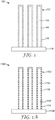
- exemplary catalyst 100 on substrate 108 has nanostructured elements 102 with microstructured whiskers 104 having outer surface 105 at least partially covered by nanoporous oxygen reduction catalyst material 106 comprising PtNiAu.
- One exemplary method for making nanoporous oxygen reduction catalyst material described herein comprises: providing an oxygen reduction catalyst material comprising PtNiAu, wherein there are layers comprising platinum and nickel; and dealloying at least some layers comprising platinum and nickel to remove nickel from at least one layer to provide a nanoporous oxygen reduction catalyst material described herein.
- the method optionally further comprises annealing the catalyst before dealloying.
- the method further optionally comprises depositing platinum and nickel from a target comprising platinum and nickel and depositing gold from a target comprising gold.
- the target is for example a Pt 3 Ni 7 target.
- the method of making the catalyst further comprises depositing platinum from a target comprising platinum, depositing nickel from a target comprising nickel, and depositing gold from a target comprising gold.
- the layers of the oxygen reduction catalyst material, before dealloying comprise platinum and nickel have a planar equivalent thickness in a range from 0.4 nm to 580 nm (in some embodiments, in a range from 0.4 nm to 72 nm) and layers comprising gold have a planar equivalent thickness in a range from 0.01 nm to 32 nm (in some embodiments, in a range from 0.01 nm to 16 nm, or even a range from 0.01 nm to 2 nm).
- the weight ratio of platinum to gold is in a range from 3:1 to 250:1 (in some embodiments, in a range from 5:1 to 15:1, from 3:1 to 30:1, from 30:1 to 250:1, or even 15:1 to 250:1).
- nanoporous oxygen reduction catalyst material described herein comprises:
- the layer(s) dealloyed are part of a catalyst such as exemplary catalyst 1100 on substrate 1108 having nanostructured elements 1102 with microstructured whiskers 1104 having outer surface 1105 at least partially covered by catalyst material 1106 comprising PtNiAu which has pores 1110.
- Suitable whiskers can be provided by techniques known in the art, including those described in U.S. Pat. Nos. 4,812,352 (Debe ), 5,039,561 (Debe ), 5,338,430 (Parsonage et al. ), 6,136,412 (Spiewak et al. ), and 7,419,741 (Vernstrom et al. ).
- nanostructured whiskers can be provided, for example, by vacuum depositing (e.g., by sublimation) a layer of organic or inorganic material onto a substrate (e.g., a microstructured catalyst transfer polymer sheet), and then, in the case of perylene red deposition, converting the perylene red pigment into nanostructured whiskers by thermal annealing.
- a substrate e.g., a microstructured catalyst transfer polymer sheet
- the vacuum deposition steps are carried out at total pressures at or below about 10 -3 Torr or 0.1 Pascal.
- Exemplary microstructures are made by thermal sublimation and vacuum annealing of the organic pigment C.I.
- Pigment Red 149 (i.e., N,N'-di(3,5-xylyl)perylene-3,4:9,10-bis(dicarboximide)).
- Methods for making organic nanostructured layers are reported, for example, in Materials Science and Engineering, A158, (1992), pp. 1-6 ; J. Vac. Sci. Technol. A, 5, (4), July/August 1987, pp. 1914-16 ; J. Vac. Sci. Technol. A, 6, (3), May/August 1988, pp. 1907-11 ; Thin Solid Films, 186, 1990, pp. 327-47 ; J. Mat. Sci., 25, 1990, pp. 5257-68 ; Rapidly Quenched Metals, Proc.
- Vacuum deposition may be carried out in any suitable apparatus (see, e.g., U.S. Pat. Nos. 5,338,430 (Parsonage et al. ), 5,879,827 (Debe et al. ), 5,879,828 (Debe et al. ), 6,040,077 (Debe et al. ), and 6,319,293 (Debe et al. ), and U.S. Pat. App. Pub. No. 2002/0004453 A1 (Haugen et al. ).
- One exemplary apparatus is depicted schematically in FIG. 4A of U.S. Pat. No. 5,338,430 (Parsonage et al.
- the substrate is mounted on a drum, which is then rotated over a sublimation or evaporation source for depositing the organic precursor (e.g., perylene red pigment) prior to annealing the organic precursor in order to form the whiskers.
- the organic precursor e.g., perylene red pigment
- the nominal thickness of deposited perylene red pigment is in a range from about 50 nm to 500 nm.
- the whiskers have an average cross-sectional dimension in a range from 20 nm to 60 nm and an average length in a range from 0.3 micrometer to 3 micrometers.
- the whiskers are attached to a backing.
- Exemplary backings comprise polyimide, nylon, metal foils, or other materials that can withstand the thermal annealing temperature up to 300°C.
- the backing has an average thickness in a range from 25 micrometers to 125 micrometers.
- the backing has a microstructure on at least one of its surfaces.
- the microstructure is comprised of substantially uniformly shaped and sized features at least three (in some embodiments, at least four, five, ten, or more) times the average size of the whiskers.
- the shapes of the microstructures can, for example, be V-shaped grooves and peaks (see, e.g., U.S. Pat. No. 6,136,412 (Spiewak et al. ), or pyramids (see, e.g., U.S. Pat. No. 7,901,829 (Debe et al. ),).
- some fraction of the microstructure features extend above the average or majority of the microstructured peaks in a periodic fashion, such as every 31 st V-groove peak being 25% or 50% or even 100% taller than those on either side of it. In some embodiments, this fraction of features that extends above the majority of the microstructured peaks can be up to 10% (in some embodiments up to 3%, 2%, or even up to 1%). Use of the occasional taller microstructure features may facilitate protecting the uniformly smaller microstructure peaks when the coated substrate moves over the surfaces of rollers in a roll-to-roll coating operation.
- the microstructure features are substantially smaller than half the thickness of the membrane that the catalyst will be transferred to in making a membrane electrode assembly. This is so that during the catalyst transfer process, the taller microstructure features do not penetrate through the membrane where they may overlap the electrode on the opposite side of the membrane. In some embodiments, the tallest microstructure features are less than 1/3 rd or 1/4 th of the membrane thickness.
- the thinnest ion exchange membranes e.g., about 10 micrometers to 15 micrometers in thickness
- the steepness of the sides of the V-shaped or other microstructured features or the included angles between adjacent features may, in some embodiments, be desirable to be on the order of 90° for ease in catalyst transfer during a lamination-transfer process and to have a gain in surface area of the electrode that comes from the square root of two (1.414) surface area of the microstructured layer relative to the planar geometric surface of the substrate backing.
- the catalyst material to be dealloyed comprises a layer comprising platinum and nickel and a layer comprising gold on the layer comprising platinum and nickel.
- layers of catalyst material to be dealloyed comprising platinum and nickel have a planar equivalent thickness in a range from 0.4 nm to 70 nm (in some embodiments, in a range from 0.4 nm to 1 nm, 0.4 nm to 5 nm, 1 nm to 25 nm, or even 1 nm to 10 nm) and layers comprising gold have a planar equivalent thickness (i.e., the thickness if deposited on a substantially flat, planar substrate) in a range from 0.01 nm to 20 nm (in some embodiments, in a range from 0.01 nm to 10 nm, 0.01 nm to 5 nm, 0.02 nm to 2.5 nm, or even 0.02 nm to 1 nm).
- layer(s) of catalyst material to be dealloyed comprising platinum and nickel collectively has a planar equivalent thickness up to 600 nm (in some embodiments, up to 575 nm, 550 nm, 500 nm, 400 nm, 300 nm, 200 nm, 100 nm, 75 nm, 50 nm, 25 nm, 10 nm, 5 nm, 2.5 nm, 1 nm, or even up to two monolayers (e.g., 0.4 nm); in some embodiments, in a range from 0.4 nm to 600 nm, 0.4 nm to 500 nm, 1 nm to 500 nm, 5 nm to 500 nm, 10 nm to 500 nm, 10 nm to 400 nm, or even 40 nm to 300 nm) and the layer comprising gold has a planar equivalent thickness up to 50 nm (in some embodiments, up to 45 nm, 40
- catalyst material to be dealloyed comprises alternating layers comprising platinum and nickel and layers comprising gold (i.e., a layer comprising platinum and nickel, a layer comprising gold, a layer comprising platinum and nickel, a layer comprising gold, etc.). In some embodiments, at least 2, 3, 4, 5, 10, 15, 20, 25, 50, 75, 100, 150, 200, 250, or even at least 275 sets of the alternating layers.
- the thickness of an individual deposited catalyst layer may depend, for example, on the areal catalyst loading of the layer and the catalyst density. For example, the thickness of a single layer of Pt with 10 micrograms of Pt per cm 2 planar area and density of 21.45 g/cm 3 deposited onto a planar substrate is calculated as 4.7 nm, and the thickness of a Ni layer with the same areal loading is 11.2 nm.
- catalyst material to be dealloyed comprises a layer comprising platinum, a layer comprising nickel on the layer comprising platinum, and a layer comprising gold on the layer comprising nickel.
- catalyst material to be dealloyed comprises a layer comprising nickel, a layer comprising platinum on the layer comprising nickel, and a layer comprising gold on the layer comprising platinum.
- catalyst material to be dealloyed comprises repeating sequential individual layers of platinum, nickel, and gold. In some embodiments, at least 2, 3, 4, 5, 10, 15, 20, 25, 50, 75, 100, 150, 200, 250, or even at least 275 sets of the repeating layers.
- catalyst material to be dealloyed has an exposed gold surface layer.
- each layer of catalyst material to be dealloyed comprising platinum and nickel independently has a planar equivalent thickness up to 100 nm (in some embodiments, up to 50 nm, 20 nm, 15 nm, 10 nm, 5 nm, 4 nm, 3 nm, 2 nm, 1 nm, a monolayer (e.g., 0.2 nm), or even up to less than a monolayer (e.g. 0.01 nm); in some embodiments, in a range from 0.01 nm to 100 nm, 0.01 nm to 50 nm, 0.1 nm to 15 nm, 0.1 nm to 10 nm, or even 1 nm to 5 nm).
- catalyst material to be dealloyed can be deposited by techniques known in the art.
- Exemplary deposition techniques include those independently selected from the group consisting of sputtering (including reactive sputtering), atomic layer deposition, molecular organic chemical vapor deposition, molecular beam epitaxy, thermal physical vapor deposition, vacuum deposition by electrospray ionization, and pulse laser deposition. Additional general details can be found, for example, in U.S. Pat. Nos. 5,879,827 (Debe et al. ), 6,040,077 (Debe et al. ), and 7,419,741 (Vernstrom et al. ), .
- the thermal physical vapor deposition method uses suitable elevated temperature (e.g., via resistive heating, electron beam gun, or laser) to melt or sublimate the target (source material) into a vapor state, which is in turn passed through a vacuum space, then condensing of the vaporized form onto substrate surfaces.
- suitable elevated temperature e.g., via resistive heating, electron beam gun, or laser
- Thermal physical vapor deposition equipment is known in the art, including that available, for example, as a metal evaporator or as an organic molecular evaporator from CreaPhys GmbH, Dresden, Germany, under the trade designations "METAL EVAPORATOR (ME-SERIES)” or “ORGANIC MOLECULAR EVAPORATOR (DE-SEREIS)” respectively; another example of an organic materials evaporator is available from Mantis Deposition LTD, Oxfordshire, UK, under the trade designation “ORGANIC MATERIALS EVAPORATIOR (ORMA-SERIES).”
- Catalyst material to be dealloyed comprising multiple alternating layers can be sputtered, for example, from multiple targets (e.g., Pt is sputtered from a first target, Ni is sputtered from a second target, and Au from a third, or from a target(s) comprising more than one element (e.g., Pt and Ni)).
- the coating layer be applied in a single step onto the gas distribution layer, gas dispersion layer, catalyst transfer layer, or membrane, so that the heat of condensation of the catalyst coating heats the underlying catalyst or support Pt, Ni, or Au atoms as applicable and substrate surface sufficient to provide enough surface mobility that the atoms are well mixed and form thermodynamically stable alloy domains.
- the substrate can also be provided hot or heated to facilitate this atomic mobility.
- sputtering is conducted at least in part in an atmosphere comprising at least a mixture of argon.
- Organometallic forms of catalysts can be deposited, for example, by soft or reactive landing of mass selected ions.
- Soft landing of mass-selected ions is used to transfer catalytically-active metal complexes complete with organic ligands from the gas phase onto an inert surface.
- This method can be used to prepare materials with defined active sites and thus achieve molecular design of surfaces in a highly controlled way under either ambient or traditional vacuum conditions.
- Johnson et al. Anal. Chem., 2010, 82, pp. 5718-5727
- Johnson et al. Chemistry: A European Journal, 2010, 16, pp. 14433-14438 .
- the weight ratio of platinum to gold of the catalyst material before or after dealloying is in a range from 3:1 to 250:1 (in some embodiments, in a range from 5:1 to 15:1, from 3:1 to 30:1, from 30:1 to 250:1, or even 15:1 to 250:1).
- methods for making catalyst material that is dealloyed comprise depositing platinum and nickel from a target comprising platinum and nickel (e.g., a Pt 3 Ni 7 target) and depositing gold from a target comprising gold.
- layers comprising platinum and nickel have a planar equivalent thickness in a range from 0.4 nm to 580 nm (in some embodiments, in a range from 0.4 nm to 72 nm) and layers comprising gold have a planar equivalent thickness in a range from 0.01 nm to 32 nm (in some embodiments, in a range from 0.01 nm to 16 nm, or even a range from 0.01 nm to 2 nm).
- methods for making catalyst described herein comprise depositing platinum from a target comprising platinum, depositing nickel from a target comprising nickel, and depositing gold from a target comprising gold.
- a layer comprising platinum, an adjacent layer comprising nickel, and an adjacent layer comprising gold collectively have a planar equivalent thickness in a range from 0.5 nm to 50 nm (in some embodiments, in a range from 0.5 nm to 30 nm).
- layers comprising platinum have a planar equivalent thickness in a range from 0.2 nm to 30 nm (in some embodiments, in a range from 0.2 nm to 20 nm, or even 0.2 nm to 10 nm)
- layers comprising nickel have a planar equivalent thickness in a range from 0.2 nm to 50 nm (in some embodiments, in a range from 0.2 nm to 25 nm, or even 0.2 nm to 10 nm)
- layers comprising gold have a planar equivalent thickness in a range from 0.01 nm to 20 nm (in some embodiments, in a range from 0.01 nm to 10 nm, 0.01 nm to 5 nm, 0.02 nm to 5 nm, 0.02 nm to 1 nm, or even 0.1 nm to 1 nm).
- the weight ratio of platinum to gold is in a range from 3:1 to 250:1 (in some embodiments, in a range from 5:1 to 15:1, from 3:1 to 30:1, from 30:1 to 250:1, or even 15:1 to 250:1).
- the nanoporosity is typically provided by dealloying the catalyst material to remove a portion of the nickel.
- dealloying can be accomplished by techniques known in the art, including via "free-corrosion” approaches (e.g., immersion in acid) or via electrochemical processing (e.g. potential cycling in acidic media).
- Nanoporosity formation typically occurs in alloys comprising at least two components with sufficiently different dissolution rates in the dealloying medium and when the more noble component has sufficient surface mobility.
- Erlebacher et al. Nature, 2001, 410, pp. 450-453 ; and U.S. Pat. Nos. 6,805,972 B2 (Erlebacher et al. ); 8,673,773 B2 (Opperman et al. ); and 8,895,206 B2 (Erlebacher et al. ).
- catalyst material to be dealloyed or the (dealloyed) nanoporous oxygen reduction catalyst material is annealed.
- the catalyst material is annealed before dealloying.
- annealing can be done by techniques known in the art, including heating the catalyst via, for example, in an oven or furnace, with a laser, and with infrared techniques. Annealing can be conducted, for example, in inert or reactive gas environments.
- annealing can induce structural changes on the atomic scale which can influence activity and durability of catalysts.
- annealing nanoscale particles and films can induce mobility in the atomic constituent(s), which can cause growth of particles or thin film grains.
- annealing can induce, for example, segregation of components within the particle or film to the surface, formation of random, disordered alloys, and formation of ordered intermetallics, depending upon the component element properties and the annealing environment.
- annealing see, for example, van der Vliet et al., Nature Materials, 2012, 11, pp. 1051-1058 ; Wang et al., Nature Materials, 2013, 12, pp. 81-87 , and U.S. Pat. No. 8,748,330 B2 (Debe et al. ).
- nanoporous oxygen reduction catalyst materials described herein is in the form of at least one nanoporous layer comprising platinum and nickel.
- nanoporous layers comprising platinum and nickel have a planar equivalent thicknesses (i.e., the thickness if deposited on a substantially flat, planar substrate) up to 600 nm (in some embodiments, up to 575 nm, 550 nm, 500 nm, 400 nm, 300 nm, 200 nm, 100 nm, 75 nm, 50 nm, 25 nm, 10 nm, 5 nm, or even up to two monolayers (e.g., 4 nm); in some embodiments, in a range from 4 nm to 600 nm, 4 nm to 500 nm, 10 nm to 500 nm, 25 nm to 500 nm, 25 nm to 400 nm, or even 40 nm to 300 nm).
- the layer comprising gold has a planar equivalent thickness up to 50 nm (in some embodiments, up to 45 nm, 40 nm, 35 nm, 30 nm, 25 nm, 20 nm, 15 nm, 10 nm, 5 nm, 4 nm, 3 nm, 2 nm, 1 nm, a monolayer (e.g., 0.2 nm) or even less than a monolayer (e.g., 0.01 nm); in some embodiments, in a range from 0.01 nm to 50 nm, 1 nm to 50 nm, 5 nm to 40 nm, or even 5 nm to 35 nm).
- Catalysts described herein are useful, for example, in fuel cell membrane electrode assemblies (MEAs).
- MEAs fuel cell membrane electrode assemblies
- Membrane electrode assembly refers to a layered sandwich of fuel cell materials comprising a membrane, anode and cathode electrode layers, and gas diffusion layers.
- the cathode catalyst layer comprises a catalyst described herein, although in some embodiments, the anode catalyst layer independently comprises a catalyst described herein.
- An MEA comprises, in order:
- Electrolyte membranes conduct reaction intermediate ions between the anode and cathode catalyst layers. Electrolyte membranes preferably have high durability in the electrochemical environment, including chemical and electrochemical oxidative stability. Electrolyte membranes preferably have low ionic resistance for the transport of the reaction intermediate ions, but are relatively impermeable barriers for other ions, electrons, and reactant species.
- the electrolyte membrane is a proton exchange membrane (PEM), which conducts cations. In PEM fuel cells, the electrolyte membrane preferably conducts protons.
- PEMs are typically a partially fluorinated or perfluorinated polymer comprised of a structural backbone and pendant cation exchange groups, PEMs are available, for example, from E.
- a gas distribution layer generally delivers gas evenly to the electrodes and, in some embodiments, conducts electricity. It also provides for removal of water in either vapor or liquid form, in the case of a fuel cell. Gas distribution layers are typically porous to allow reactant and product transport between the electrodes and the flow field. Sources of gas distribution layers include carbon fibers randomly oriented to form porous layers, in the form of non-woven paper or woven fabrics.
- the non-woven carbon papers are available, for example, from Mitsubishi Rayon Co., Ltd., Tokyo, Japan, under the trade designation "GRAFIL U-105;” Toray Corp., Tokyo, Japan, under the trade designation “TORAY;” AvCarb Material Solutions, Lowell, MA, under the trade designation "AVCARB;” SGL Group, the Carbon Company, Wiesbaden, Germany, under the trade designation "SIGRACET;” Freudenberg FCCT SE & Co.
- non-woven paper or woven fabrics can be treated to modify its hydrophobicity (e.g., treatment with a polytetrafluoroethylene (PTFE) suspension with subsequent drying and annealing).
- PTFE polytetrafluoroethylene
- Gas dispersion layers often comprise a porous layer of sub-micrometer electronically-conductive particles (e.g., carbon), and a binder (e.g., PTFE).
- a binder e.g., PTFE
- At least one of the anode or cathode catalyst has whiskers with nanoporous oxygen reduction catalyst material described herein.
- the "other catalyst layer” can be a conventional catalyst known in the art, and provided by techniques known in the art (e.g., U.S. Pat. Nos. 5,759,944 (Buchanan et al. ), 5,068,161 (Keck et al. ), and 4,447,506 (Luczak et al. )).
- the cathode and/or anode catalyst layer comprises whiskers with nanoporous oxygen reduction catalyst material described herein.
- a fuel cell is an electrochemical device that combines hydrogen fuel and oxygen from the air to produce electricity, heat, and water. Fuel cells do not utilize combustion, and as such, fuel cells produce little if any hazardous effluents. Fuel cells convert hydrogen fuel and oxygen directly into electricity, and can be operated at much higher efficiencies than internal combustion electric generators, for example.
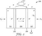
- exemplary fuel cell 200 includes first gas distribution layer 201 adjacent to anode 203. Adjacent anode 203 is an electrolyte membrane 204. Cathode 205 is situated adjacent electrolyte membrane 204, and second gas distribution layer 207 is situated adjacent cathode 205.
- hydrogen fuel is introduced into the anode portion of the fuel cell 200, passing through first gas distribution layer 201 and over anode 203. At anode 203, the hydrogen fuel is separated into hydrogen ions (H + ) and electrons (e - ).
- Electrolyte membrane 204 permits only the hydrogen ions or protons to pass through electrolyte membrane 204 to the cathode portion of fuel cell 200.
- the electrons cannot pass through the electrolyte membrane 204 and, instead, flow through an external electrical circuit in the form of electric current.
- This current can power an electric load 217, such as an electric motor, or be directed to an energy storage device, such as a rechargeable battery.
- Nanostructured whiskers employed as catalyst supports were made according to the process described in U.S. Pat. Nos. 5,338,430 (Parsonage et al. ), 4,812,352 (Debe ), and 5,039,561 (Debe ), using as substrates the microstructured catalyst transfer substrates (or MCTS) described in U.S. Pat. No. 6,136,412 .
- Perylene red pigment i.e., N,N'-di(3,5-xylyl)perylene-3,4:9,10-bis(dicarboximide)
- Pigment Red 149 also known as "PR149", obtained from Clariant, Charlotte, NC
- PR149 obtained from Clariant, Charlotte, NC
- highly oriented crystal structures were formed with large aspect ratios, controllable lengths of about 0.5 to 2 micrometers, widths of about 0.03-0.05 micrometer and areal number density of about 30 whiskers per square micrometer, oriented substantially normal to the underlying substrate.
- Nanostructured thin film (NSTF) catalyst layers were prepared by sputter coating catalyst films sequentially using a DC-magnetron sputtering process onto the layer of nanostructured whiskers.
- a vacuum sputter deposition system (obtained as Model Custom Research from Mill Lane Engineering Co., Lowell, MA) equipped with 4 cryo-pumps (obtained from Austin Scientific, Oxford Instruments, Austin, TX), a turbopump and using typical Ar sputter gas pressures of about 5 mTorr (0.66 Pa), and 2 inch x 10 inch (5 cm x 25.4 cm) rectangular sputter targets (obtained from Sophisticated Alloys, Inc., Butler, PA) was used.
- the coatings were deposited by using ultra high purity Ar as the sputtering gas.
- Pt and Ni were first simultaneously deposited from a single alloy Pt 3 Ni 7 target (30 at.% Pt and 70 at.% Ni, obtained from Sophisticated Alloys, Butler, PA). 50 layers of Pt 3 Ni 7 were deposited, each with about 2.8 nm planar equivalent thickness, resulting in an areal Pt loading of about 0.10 mg Pt /cm 2 .
- Pt 3 Ni 7 catalysts deposited from a single alloy target are referred to as "single target" (ST).
- Au obtained from Materion, Mayfield Heights, OH was then subsequently deposited onto the surface of four pieces of the Pt 3 Ni 7 -coated NSTF catalyst on substrate, each with a different Au areal loading calculated to yield 1, 2, 5, and 10 at.% Au content in the electrocatalyst (Examples 1, 2, 3, and 4, respectively).
- the Au layer planar equivalent thickness for Examples 1, 2, 3, and 4 was 2.1 nm, 4.1 nm, 9.8 nm, and 20.2 nm, respectively.
- Pt-to-Au weight ratios for Examples 1, 2, 3, and 4 were 29.4:1, 14.7:1, 5.8:1, and 2.8:1, respectively.
- Representative areas of the electrocatalysts were analyzed for bulk composition using X-Ray Fluorescence spectroscopy (XRF).
- Representative catalyst samples were evaluated on MCTS using a wavelength dispersive X-ray fluorescence spectrometer (obtained under the trade designation " PRIMUS II” from Rigaku Corporation, Tokyo, Japan ) equipped with a rhodium (Rh) X-ray source, a vacuum atmosphere, and a 20 mm diameter measurement area. Each sample was analyzed three times to obtain the average and standard deviation for the measured Pt, Ni, and Au signal intensities, which are proportional to loading.
- XRF X-Ray Fluorescence spectroscopy
- the electrocatalysts' Pt, Ni, and Au areal loadings of Examples 1-4 were determined by comparing their measured XRF intensities to the XRF intensities obtained with standard NSTF electrocatalysts containing Pt, Ni, and Au with known areal loadings. From the XRF-determined Pt, Ni, and Au areal loadings, the catalysts' composition and Pt-to-Au weight ratios were calculated. The total platinum group metal (PGM) content was determined by adding the Pt and Au areal loadings. Loading and composition information is provided in Table 1, below.
- the Pt x Ni y Au z catalysts and NSTF PtCoMn coated anode catalyst whiskers (0.05 mg Pt /cm 2 , Pt 69 Co 28 Mn 3 ) on MCTS were then transferred to either side of a 24-micrometer thick proton exchange membrane (available under the trade designation "3M PFSA 825EW” (neat) from 3M Company, St. Paul, MN), using a laminator (obtained under the trade designation "HL-101” from Chem Instruments, Inc., West Chester Township, OH) to form a catalyst coated membrane (CCM).
- a 24-micrometer thick proton exchange membrane available under the trade designation "3M PFSA 825EW” (neat) from 3M Company, St. Paul, MN
- a laminator obtained under the trade designation "HL-101” from Chem Instruments, Inc., West Chester Township, OH
- the three-layer stack-up was hand fed into the laminator with hot nip rolls at 270°F (132°C), 150 psi (1.03 MPa) nip, and rotating at the equivalent of 0.5 fpm (0.25 cm/s). Immediately after lamination, the MCTS layers were peeled back, leaving the catalyst coated whiskers embedded into either side of the PEM.
- the CCM was installed with identical gas diffusion layers (available under the trade designation “3M 2979 GAS DIFFUSION LAYERS” from 3M Company) on the anode and cathode in 50 cm 2 active area test cells (obtained under the trade designation "50 CM2 CELL HARDWARE” from Fuel Cell Technologies, Inc., Albuquerque, NM) with quad-serpentine flow fields with gaskets selected to give 10% compression of the gas diffusion layers.
- the catalyst of the present invention was evaluated as the fuel cell cathode.
- test cells were connected to a test station (obtained under the trade designation "SINGLE FUEL CELL TEST STATION” from Fuel Cell Technologies, Inc.).
- the MEA was then operated for about 40 hours under a conditioning protocol to achieve apparent steady state performance.
- the protocol consisted of repeated cycles of operational and shutdown phases, each about 40 and 45 minutes in duration, respectively.
- the MEA was operated at 75°C cell temperature, 70°C dew point, 101/101 kPaA H 2 /Air, with constant flow rates of 800 and 1800 sccm of H 2 and air, respectively.
- the cell voltage was alternated between 5-minute long polarization cycles between 0.85 V and 0.25 V and 5-minute long potential holds at 0.40 V.
- the cell potential was set to open circuit voltage, H 2 and air flows to the cell were halted, and the cell temperature was cooled towards room temperature, while liquid water was injected into the anode and cathode cell inlets at 0.26 g/min. and 0.40 g/min., respectively.
- the fuel cell conditioning protocol which includes numerous potential cycles, may induce formation of nanopores within the electrocatalyst.
- the electrocatalysts were characterized for relevant beginning of life (BOL) characteristics, including catalyst activity, surface area, and operational performance under relevant H 2 /Air test conditions, described as follows.
- BOL beginning of life
- the cathode oxygen reduction reaction (ORR) absolute activity was measured with saturated 150 kPaA H 2 /O 2 , 80°C cell temperature for 1200 seconds at 900 mV vs. the 100% H2 reference/counter electrode.
- the ORR absolute activity (A/cm 2 or mA/cm 2 ) was obtained by adding the measured current density after 1050 seconds of hold time and the electronic shorting and hydrogen crossover current densities, estimated from 2 mV/s cyclic voltammograms measured with N 2 fed to the working electrode instead of O 2 .
- the electrocatalyst mass activity is calculated by dividing the corrected ORR absolute activity (A/cm 2 planar ) by the cathode Pt or PGM areal loading (mg/cm 2 ) to obtain the mass activity (A/mg Pt or A/mg PGM ).
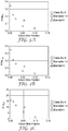
- the electrocatalyst mass activity is provided in Table 2, below, and FIGS. 3A and 3B .
- Table 2 Example Au Incorporation Au Content Specific Area ORR Mass Activity H 2 /Air Performance at.% m 2 /g Pt m 2 /g PGM A/mg Pt A/mg PGM Volts Comp. Ex. A none 0 16.1 16.1 0.35 0.35 0.892 Ex.
- the cathode catalyst surface enhancement factor (SEF, m 2 Pt /m 2 planar or analogously cm 2 Pt /cm 2 planar ) was measured via cyclic voltammetry (100 mV/s, 0.65 V-0.85 V, average of 100 scans) under saturated 101 kilopascals absolute pressure (kPaA) H 2 /N 2 and 70°C cell temperature.
- the SEF was estimated by taking the average of the integrated hydrogen underpotential deposition (H UPD ) charge ( ⁇ C/cm 2 planar ) for the oxidative and reductive waves and dividing by 220 ⁇ C/cm 2 Pt .
- the electrocatalyst's specific surface area (m 2 Pt /g pt or m 2 Pt /g PGM ), a measure of catalyst dispersion, was calculated by dividing the SEF (m 2 Pt /m 2 planar ) by the areal Pt or total platinum group metal (PGM) loading (g Pt /m 2 planar or g PGM /m 2 planar ).
- the electrocatalyst specific area is provided in Table 2, above, and FIGS. 3C and 3D .
- the operational performance of electrocatalysts was evaluated via H 2 /Air polarization curves, measured at 80°C cell temperature, 68°C dew point, 150/150 kPaA H 2 /Air, with constant stoichiometry of 2.0 H2 and 2.5 for air.
- the current density was initially set to 20 mA/cm 2 , and then stepwise increased while the cell voltage was maintained above 0.40 V, after which the current density was stepwise decreased back to 20 mA/cm 2 .
- the cell was held at each current density for 2 minutes.
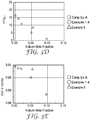
- the cell voltage at a specific current density, 20 mA/cm 2 is reported as "H 2 /Air Performance" and is reported in Table 2, above, and FIG. 3E .
- Example 2 catalyst was additionally evaluated under an accelerated stress test (AST), which evaluated the stability of the electrocatalyst metal.
- AST accelerated stress test
- the cell was operated at 80°C cell temperature, 200/200 sccm H 2 /N 2 , 101kPaA, 100% inlet relative humidity (RH), and the cathode electrode potential was cycled between 0.6 V-1.0 V vs. the hydrogen counter/reference electrode at a scan rate of 50 mV/s.
- AST protocol which includes numerous potential cycles, may induce formation of nanopores within the electrocatalyst.
- the MEA was reconditioned for about 16 hours using the initial conditioning protocol, after which the cathode surface area, ORR activity, and H 2 /Air polarization curves were again measured to determine the rate and extent of performance loss.
- This process of AST, reconditioning, and characterization was repeated such that the cell was exposed to a total of 30,000 AST cycles.
- the changes in specific area, mass activity, and H 2 /Air performance after the 30,000 AST cycles are listed in Table 3, below.
- Table 3 Experiment Au Incorporation Au Content Specific Area ORR Mass Activity H 2 /Air Performance at.% m 2 /g PGM % Change A/mg PGM % Change Volts Change Comp. Ex.
- Example 5 was prepared and evaluated as described for Examples 1-4, except that the Au metal was incorporated into the alloy during deposition of the Pt 3 Ni 7 .
- a first "ST" Pt 3 Ni 7 layer was deposited with about 1 nm planar equivalent thickness, onto which an Au layer was deposited.
- the Au planar equivalent thicknesses were about 0.08 nm. This deposition process was repeated 135 times until an areal Pt loading of about 0.10 mg Pt /cm 2 was achieved.
- Table 1 Loading and composition information is provided in Table 1, above.
- the catalyst mass activity, specific area, and H 2 /Air performance after initial conditioning are reported in Table 2, above, and shown in FIGS. 3A, 3B, 3C , 3D, and 3E .
- the changes in specific area, mass activity, and H 2 /Air performance after the 30,000 AST cycles tested are listed in Table 3, above.
- Comparative Example A was prepared and evaluated as described for Example 1, except that no Au was incorporated into the catalyst.
- Table 1 Loading and composition information is provided in Table 1, above.
- the catalyst specific area, mass activity, and H 2 /Air performance after initial conditioning are reported in Table 2, above, and shown in FIGS. 3A, 3B, 3C , 3D, and 3E .
- the changes in specific area, mass activity, and H 2 /Air performance after the 30,000 AST cycles tested are listed in Table 3, above.
- Comparative Example B was prepared and evaluated as described for Comparative Example A, except that during electrocatalyst deposition the Pt 3 Ni 7 loading and layer planar equivalent thickness differed and it was not evaluated under the AST durability test. Three layers of Pt 3 Ni 7 were deposited, each with about 52 nm planar equivalent thickness, resulting in a Pt areal loading of about 0.125 mg Pt /cm 2 .
- Examples 6-10 were prepared and evaluated as described for Comparative Example B, except that Au was deposited onto the surface after deposition of Pt 3 Ni 7 , Au was deposited with an e-beam coater, and Au loading was determined within the e-beam coater.
- Example 6 a layer of Au was coated onto NSTF catalyst prepared above by using an e-beam coater equipment (obtained as Model MK-50, from CHA Industries, Fremont, CA).
- One planetary rotator mounted with NSTF catalyst as a substrate rotated inside the system under vacuum with the 270 degree electron beam heating the Au source to its sublimation point.
- the deposited amount of Au and the deposition rate were monitored in real time using a quartz crystal monitor (obtained under the trade designation "INFICON;" Model 6000, from CHA Industries, Fremont, CA).
- the power to the electron beam was terminated and the deposition ended. The system was then vented and the substrates removed.
- Examples 7, 8, 9, and 10 were prepared as described for Example 6, but the Au loadings were 1.0, 1.4, 1.9, and 3.9 microgram/cm 2 , respectively.
- Au content for Examples 6, 7, 8, 9, and 10 were 0.1, 0.2, 0.3, 0.5, and 0.9 at.%, respectively.
- Au layer planar equivalent thicknesses for Examples 6, 7, 8, 9, and 10 were 0.26 nm, 0.52 nm, 0.75 nm, 1.0 nm, and 2.0 nm, respectively.
- Pt-to-Au weight ratios for Examples 6, 7, 8, 9, and 10 were 250:1, 125:1, 86.8:1, 64.4:1, and 32.4:1, respectively.
Landscapes
- Chemical & Material Sciences (AREA)
- Chemical Kinetics & Catalysis (AREA)
- Electrochemistry (AREA)
- General Chemical & Material Sciences (AREA)
- Engineering & Computer Science (AREA)
- Materials Engineering (AREA)
- Composite Materials (AREA)
- Organic Chemistry (AREA)
- Catalysts (AREA)
- Inert Electrodes (AREA)
- Fuel Cell (AREA)
Applications Claiming Priority (2)
| Application Number | Priority Date | Filing Date | Title |
|---|---|---|---|
| US201662413192P | 2016-10-26 | 2016-10-26 | |
| PCT/US2017/056110 WO2018080794A1 (en) | 2016-10-26 | 2017-10-11 | Catalyst |
Publications (2)
| Publication Number | Publication Date |
|---|---|
| EP3533097A1 EP3533097A1 (en) | 2019-09-04 |
| EP3533097B1 true EP3533097B1 (en) | 2021-04-21 |
Family
ID=60191485
Family Applications (1)
| Application Number | Title | Priority Date | Filing Date |
|---|---|---|---|
| EP17791803.4A Active EP3533097B1 (en) | 2016-10-26 | 2017-10-11 | Catalyst |
Country Status (6)
| Country | Link |
|---|---|
| US (1) | US11196055B2 (enExample) |
| EP (1) | EP3533097B1 (enExample) |
| JP (1) | JP2019534146A (enExample) |
| KR (1) | KR20190069523A (enExample) |
| CN (1) | CN109891645A (enExample) |
| WO (1) | WO2018080794A1 (enExample) |
Families Citing this family (6)
| Publication number | Priority date | Publication date | Assignee | Title |
|---|---|---|---|---|
| JP7055971B2 (ja) | 2016-10-26 | 2022-04-19 | スリーエム イノベイティブ プロパティズ カンパニー | 燃料電池用pt-ni-ir触媒 |
| KR20190076999A (ko) | 2016-10-26 | 2019-07-02 | 쓰리엠 이노베이티브 프로퍼티즈 캄파니 | 촉매 |
| CN108711626A (zh) * | 2018-05-17 | 2018-10-26 | 天津理工大学 | 一种燃料电池膜电极催化剂及其制备方法 |
| CN108695523B (zh) * | 2018-05-17 | 2022-05-13 | 天津理工大学 | 一种燃料电池膜电极催化剂及其制备方法 |
| CN108736020A (zh) * | 2018-05-17 | 2018-11-02 | 天津理工大学 | 一种燃料电池膜电极催化剂及其制备方法 |
| US12435434B2 (en) * | 2022-02-10 | 2025-10-07 | Uop Llc | Method for conditioning an electrolysis system |
Family Cites Families (41)
| Publication number | Priority date | Publication date | Assignee | Title |
|---|---|---|---|---|
| US3637437A (en) | 1970-06-03 | 1972-01-25 | Catalytic Technology Corp | Raney metal sheet material |
| GB1501102A (en) * | 1974-02-19 | 1978-02-15 | Shell Int Research | Method for the production of a composite catalyst suitable for use in forming fuel cell electrodes |
| US4340276A (en) | 1978-11-01 | 1982-07-20 | Minnesota Mining And Manufacturing Company | Method of producing a microstructured surface and the article produced thereby |
| US4447506A (en) | 1983-01-17 | 1984-05-08 | United Technologies Corporation | Ternary fuel cell catalysts containing platinum, cobalt and chromium |
| US4568598A (en) | 1984-10-30 | 1986-02-04 | Minnesota Mining And Manufacturing Company | Article with reduced friction polymer sheet support |
| US5039561A (en) | 1986-08-25 | 1991-08-13 | Minnesota Mining And Manufacturing Company | Method for preparing an article having surface layer of uniformly oriented, crystalline, organic microstructures |
| US4812352A (en) | 1986-08-25 | 1989-03-14 | Minnesota Mining And Manufacturing Company | Article having surface layer of uniformly oriented, crystalline, organic microstructures |
| US5068161A (en) | 1990-03-30 | 1991-11-26 | Johnson Matthey Public Limited Company | Catalyst material |
| US5338430A (en) | 1992-12-23 | 1994-08-16 | Minnesota Mining And Manufacturing Company | Nanostructured electrode membranes |
| US5759944A (en) | 1993-04-20 | 1998-06-02 | Johnson Matthey Public Limited Company | Catalyst material |
| GB9308094D0 (en) * | 1993-04-20 | 1993-06-02 | Johnson Matthey Plc | Improved catalyst material |
| US5879828A (en) | 1997-10-10 | 1999-03-09 | Minnesota Mining And Manufacturing Company | Membrane electrode assembly |
| US6136412A (en) | 1997-10-10 | 2000-10-24 | 3M Innovative Properties Company | Microtextured catalyst transfer substrate |
| US5879827A (en) * | 1997-10-10 | 1999-03-09 | Minnesota Mining And Manufacturing Company | Catalyst for membrane electrode assembly and method of making |
| US6482763B2 (en) | 1999-12-29 | 2002-11-19 | 3M Innovative Properties Company | Suboxide fuel cell catalyst for enhanced reformate tolerance |
| US6884539B2 (en) * | 2002-07-02 | 2005-04-26 | Microcell Corporation | Microcell electrochemical devices and assemblies with corrosion-resistant current collectors, and method of making the same |
| US6805972B2 (en) | 2002-08-27 | 2004-10-19 | Johns Hopkins University | Method of forming nanoporous membranes |
| US6946362B2 (en) | 2002-09-06 | 2005-09-20 | Hewlett-Packard Development Company, L.P. | Method and apparatus for forming high surface area material films and membranes |
| US7419741B2 (en) | 2003-09-29 | 2008-09-02 | 3M Innovative Properties Company | Fuel cell cathode catalyst |
| US7485211B2 (en) | 2003-10-10 | 2009-02-03 | Ohio University | Electro-catalysts for the oxidation of ammonia in alkaline media |
| GB0400166D0 (en) * | 2004-01-06 | 2004-02-11 | Ic Innovations Ltd | Catalyst |
| US7855021B2 (en) | 2004-12-22 | 2010-12-21 | Brookhaven Science Associates, Llc | Electrocatalysts having platium monolayers on palladium, palladium alloy, and gold alloy core-shell nanoparticles, and uses thereof |
| CN100407482C (zh) * | 2005-06-22 | 2008-07-30 | 新源动力股份有限公司 | 抗一氧化碳复合阳极电极催化层结构及制备方法 |
| US7901829B2 (en) | 2005-09-13 | 2011-03-08 | 3M Innovative Properties Company | Enhanced catalyst interface for membrane electrode assembly |
| DE102006014067A1 (de) | 2006-03-27 | 2007-10-04 | Universität Bremen | Goldhaltiger Katalysator mit poröser Struktur |
| CN101631614B (zh) * | 2006-10-17 | 2013-12-11 | 路慕斯技术有限公司 | 双金属烷基化催化剂 |
| DE102007055019B4 (de) | 2007-11-14 | 2019-04-04 | Fraunhofer-Gesellschaft zur Förderung der angewandten Forschung e.V. | Verfahren zum Herstellen einer nanoporösen Schicht |
| US8231773B2 (en) | 2007-12-11 | 2012-07-31 | GM Global Technology Operations LLC | Method of treating nanoparticles using an intermittently processing electrochemical cell |
| CN102132447B (zh) | 2008-08-25 | 2013-12-18 | 3M创新有限公司 | 具有电压反转容限的燃料电池纳米催化剂 |
| US20100304268A1 (en) | 2009-05-28 | 2010-12-02 | Tetsuo Kawamura | Ternary alloy catalysts for fuel cells |
| WO2010138138A1 (en) * | 2009-05-28 | 2010-12-02 | The Johns Hopkins University | Porous metal catalysts for oxygen reduction |
| JP5973423B2 (ja) | 2010-04-26 | 2016-08-23 | スリーエム イノベイティブ プロパティズ カンパニー | アニーリングされたナノ構造薄膜触媒 |
| JP6010529B2 (ja) * | 2010-04-26 | 2016-10-19 | スリーエム イノベイティブ プロパティズ カンパニー | 白金ニッケル触媒合金 |
| CA2851494A1 (en) | 2011-10-10 | 2013-04-18 | 3M Innovative Properties Company | Catalyst electrodes, and methods of making and using the same |
| CN102534742A (zh) | 2012-01-14 | 2012-07-04 | 天津大学 | 一种二氧化钛纳米薄膜复合材料及其恒电流制备方法 |
| US9101915B2 (en) | 2012-12-18 | 2015-08-11 | Umicore Ag & Co. Kg | Catalyst particles comprising a layered core-shell-shell structure and method of their manufacture |
| KR20150098647A (ko) | 2012-12-19 | 2015-08-28 | 쓰리엠 이노베이티브 프로퍼티즈 캄파니 | 나노구조화된 휘스커 물품 |
| US10099207B2 (en) * | 2015-04-02 | 2018-10-16 | Uchicago Argonne, Llc | Multimetallic core/interlayer/shell nanoparticles |
| KR20190076999A (ko) | 2016-10-26 | 2019-07-02 | 쓰리엠 이노베이티브 프로퍼티즈 캄파니 | 촉매 |
| JP7055971B2 (ja) | 2016-10-26 | 2022-04-19 | スリーエム イノベイティブ プロパティズ カンパニー | 燃料電池用pt-ni-ir触媒 |
| KR20190069524A (ko) | 2016-10-26 | 2019-06-19 | 쓰리엠 이노베이티브 프로퍼티즈 캄파니 | 연료 전지용 Pt-Ni-Ir 촉매 |
-
2017
- 2017-10-11 EP EP17791803.4A patent/EP3533097B1/en active Active
- 2017-10-11 KR KR1020197014373A patent/KR20190069523A/ko not_active Withdrawn
- 2017-10-11 WO PCT/US2017/056110 patent/WO2018080794A1/en not_active Ceased
- 2017-10-11 US US16/344,773 patent/US11196055B2/en not_active Expired - Fee Related
- 2017-10-11 JP JP2019522355A patent/JP2019534146A/ja active Pending
- 2017-10-11 CN CN201780066409.5A patent/CN109891645A/zh active Pending
Non-Patent Citations (1)
| Title |
|---|
| None * |
Also Published As
| Publication number | Publication date |
|---|---|
| JP2019534146A (ja) | 2019-11-28 |
| EP3533097A1 (en) | 2019-09-04 |
| KR20190069523A (ko) | 2019-06-19 |
| US20190260035A1 (en) | 2019-08-22 |
| CN109891645A (zh) | 2019-06-14 |
| US11196055B2 (en) | 2021-12-07 |
| WO2018080794A1 (en) | 2018-05-03 |
Similar Documents
| Publication | Publication Date | Title |
|---|---|---|
| EP3533099B1 (en) | Pt-ni-ir catalyst for fuel cell | |
| US11936050B2 (en) | Pt—Ni—Ir catalyst for fuel cell | |
| EP3533097B1 (en) | Catalyst | |
| EP3533096B1 (en) | Catalyst | |
| US11973232B2 (en) | Catalyst | |
| EP3776702B1 (en) | Catalyst comprising pt, ni, and ta | |
| US11404702B2 (en) | Catalyst comprising Pt, Ni, and Cr | |
| US11955645B2 (en) | Catalyst | |
| EP3776704B1 (en) | Catalyst | |
| US20210008528A1 (en) | Catalyst comprising pt, ni, and ru | |
| EP3895238B1 (en) | Catalyst | |
| US12620601B2 (en) | Catalyst |
Legal Events
| Date | Code | Title | Description |
|---|---|---|---|
| STAA | Information on the status of an ep patent application or granted ep patent |
Free format text: STATUS: UNKNOWN |
|
| STAA | Information on the status of an ep patent application or granted ep patent |
Free format text: STATUS: THE INTERNATIONAL PUBLICATION HAS BEEN MADE |
|
| PUAI | Public reference made under article 153(3) epc to a published international application that has entered the european phase |
Free format text: ORIGINAL CODE: 0009012 |
|
| STAA | Information on the status of an ep patent application or granted ep patent |
Free format text: STATUS: REQUEST FOR EXAMINATION WAS MADE |
|
| 17P | Request for examination filed |
Effective date: 20190430 |
|
| AK | Designated contracting states |
Kind code of ref document: A1 Designated state(s): AL AT BE BG CH CY CZ DE DK EE ES FI FR GB GR HR HU IE IS IT LI LT LU LV MC MK MT NL NO PL PT RO RS SE SI SK SM TR |
|
| AX | Request for extension of the european patent |
Extension state: BA ME |
|
| DAV | Request for validation of the european patent (deleted) | ||
| DAX | Request for extension of the european patent (deleted) | ||
| STAA | Information on the status of an ep patent application or granted ep patent |
Free format text: STATUS: EXAMINATION IS IN PROGRESS |
|
| 17Q | First examination report despatched |
Effective date: 20200330 |
|
| GRAP | Despatch of communication of intention to grant a patent |
Free format text: ORIGINAL CODE: EPIDOSNIGR1 |
|
| STAA | Information on the status of an ep patent application or granted ep patent |
Free format text: STATUS: GRANT OF PATENT IS INTENDED |
|
| INTG | Intention to grant announced |
Effective date: 20201113 |
|
| GRAS | Grant fee paid |
Free format text: ORIGINAL CODE: EPIDOSNIGR3 |
|
| GRAA | (expected) grant |
Free format text: ORIGINAL CODE: 0009210 |
|
| STAA | Information on the status of an ep patent application or granted ep patent |
Free format text: STATUS: THE PATENT HAS BEEN GRANTED |
|
| AK | Designated contracting states |
Kind code of ref document: B1 Designated state(s): AL AT BE BG CH CY CZ DE DK EE ES FI FR GB GR HR HU IE IS IT LI LT LU LV MC MK MT NL NO PL PT RO RS SE SI SK SM TR |
|
| REG | Reference to a national code |
Ref country code: GB Ref legal event code: FG4D |
|
| REG | Reference to a national code |
Ref country code: CH Ref legal event code: EP |
|
| REG | Reference to a national code |
Ref country code: DE Ref legal event code: R096 Ref document number: 602017037210 Country of ref document: DE |
|
| REG | Reference to a national code |
Ref country code: IE Ref legal event code: FG4D |
|
| REG | Reference to a national code |
Ref country code: AT Ref legal event code: REF Ref document number: 1385589 Country of ref document: AT Kind code of ref document: T Effective date: 20210515 |
|
| REG | Reference to a national code |
Ref country code: LT Ref legal event code: MG9D |
|
| REG | Reference to a national code |
Ref country code: AT Ref legal event code: MK05 Ref document number: 1385589 Country of ref document: AT Kind code of ref document: T Effective date: 20210421 |
|
| REG | Reference to a national code |
Ref country code: NL Ref legal event code: MP Effective date: 20210421 |
|
| PG25 | Lapsed in a contracting state [announced via postgrant information from national office to epo] |
Ref country code: NL Free format text: LAPSE BECAUSE OF FAILURE TO SUBMIT A TRANSLATION OF THE DESCRIPTION OR TO PAY THE FEE WITHIN THE PRESCRIBED TIME-LIMIT Effective date: 20210421 Ref country code: HR Free format text: LAPSE BECAUSE OF FAILURE TO SUBMIT A TRANSLATION OF THE DESCRIPTION OR TO PAY THE FEE WITHIN THE PRESCRIBED TIME-LIMIT Effective date: 20210421 Ref country code: AT Free format text: LAPSE BECAUSE OF FAILURE TO SUBMIT A TRANSLATION OF THE DESCRIPTION OR TO PAY THE FEE WITHIN THE PRESCRIBED TIME-LIMIT Effective date: 20210421 Ref country code: BG Free format text: LAPSE BECAUSE OF FAILURE TO SUBMIT A TRANSLATION OF THE DESCRIPTION OR TO PAY THE FEE WITHIN THE PRESCRIBED TIME-LIMIT Effective date: 20210721 Ref country code: FI Free format text: LAPSE BECAUSE OF FAILURE TO SUBMIT A TRANSLATION OF THE DESCRIPTION OR TO PAY THE FEE WITHIN THE PRESCRIBED TIME-LIMIT Effective date: 20210421 Ref country code: LT Free format text: LAPSE BECAUSE OF FAILURE TO SUBMIT A TRANSLATION OF THE DESCRIPTION OR TO PAY THE FEE WITHIN THE PRESCRIBED TIME-LIMIT Effective date: 20210421 |
|
| PG25 | Lapsed in a contracting state [announced via postgrant information from national office to epo] |
Ref country code: IS Free format text: LAPSE BECAUSE OF FAILURE TO SUBMIT A TRANSLATION OF THE DESCRIPTION OR TO PAY THE FEE WITHIN THE PRESCRIBED TIME-LIMIT Effective date: 20210821 Ref country code: GR Free format text: LAPSE BECAUSE OF FAILURE TO SUBMIT A TRANSLATION OF THE DESCRIPTION OR TO PAY THE FEE WITHIN THE PRESCRIBED TIME-LIMIT Effective date: 20210722 Ref country code: SE Free format text: LAPSE BECAUSE OF FAILURE TO SUBMIT A TRANSLATION OF THE DESCRIPTION OR TO PAY THE FEE WITHIN THE PRESCRIBED TIME-LIMIT Effective date: 20210421 Ref country code: RS Free format text: LAPSE BECAUSE OF FAILURE TO SUBMIT A TRANSLATION OF THE DESCRIPTION OR TO PAY THE FEE WITHIN THE PRESCRIBED TIME-LIMIT Effective date: 20210421 Ref country code: NO Free format text: LAPSE BECAUSE OF FAILURE TO SUBMIT A TRANSLATION OF THE DESCRIPTION OR TO PAY THE FEE WITHIN THE PRESCRIBED TIME-LIMIT Effective date: 20210721 Ref country code: LV Free format text: LAPSE BECAUSE OF FAILURE TO SUBMIT A TRANSLATION OF THE DESCRIPTION OR TO PAY THE FEE WITHIN THE PRESCRIBED TIME-LIMIT Effective date: 20210421 Ref country code: PT Free format text: LAPSE BECAUSE OF FAILURE TO SUBMIT A TRANSLATION OF THE DESCRIPTION OR TO PAY THE FEE WITHIN THE PRESCRIBED TIME-LIMIT Effective date: 20210823 Ref country code: PL Free format text: LAPSE BECAUSE OF FAILURE TO SUBMIT A TRANSLATION OF THE DESCRIPTION OR TO PAY THE FEE WITHIN THE PRESCRIBED TIME-LIMIT Effective date: 20210421 |
|
| REG | Reference to a national code |
Ref country code: DE Ref legal event code: R097 Ref document number: 602017037210 Country of ref document: DE |
|
| PG25 | Lapsed in a contracting state [announced via postgrant information from national office to epo] |
Ref country code: SM Free format text: LAPSE BECAUSE OF FAILURE TO SUBMIT A TRANSLATION OF THE DESCRIPTION OR TO PAY THE FEE WITHIN THE PRESCRIBED TIME-LIMIT Effective date: 20210421 Ref country code: SK Free format text: LAPSE BECAUSE OF FAILURE TO SUBMIT A TRANSLATION OF THE DESCRIPTION OR TO PAY THE FEE WITHIN THE PRESCRIBED TIME-LIMIT Effective date: 20210421 Ref country code: EE Free format text: LAPSE BECAUSE OF FAILURE TO SUBMIT A TRANSLATION OF THE DESCRIPTION OR TO PAY THE FEE WITHIN THE PRESCRIBED TIME-LIMIT Effective date: 20210421 Ref country code: CZ Free format text: LAPSE BECAUSE OF FAILURE TO SUBMIT A TRANSLATION OF THE DESCRIPTION OR TO PAY THE FEE WITHIN THE PRESCRIBED TIME-LIMIT Effective date: 20210421 Ref country code: DK Free format text: LAPSE BECAUSE OF FAILURE TO SUBMIT A TRANSLATION OF THE DESCRIPTION OR TO PAY THE FEE WITHIN THE PRESCRIBED TIME-LIMIT Effective date: 20210421 Ref country code: RO Free format text: LAPSE BECAUSE OF FAILURE TO SUBMIT A TRANSLATION OF THE DESCRIPTION OR TO PAY THE FEE WITHIN THE PRESCRIBED TIME-LIMIT Effective date: 20210421 Ref country code: ES Free format text: LAPSE BECAUSE OF FAILURE TO SUBMIT A TRANSLATION OF THE DESCRIPTION OR TO PAY THE FEE WITHIN THE PRESCRIBED TIME-LIMIT Effective date: 20210421 |
|
| PGFP | Annual fee paid to national office [announced via postgrant information from national office to epo] |
Ref country code: DE Payment date: 20210921 Year of fee payment: 5 |
|
| PLBE | No opposition filed within time limit |
Free format text: ORIGINAL CODE: 0009261 |
|
| STAA | Information on the status of an ep patent application or granted ep patent |
Free format text: STATUS: NO OPPOSITION FILED WITHIN TIME LIMIT |
|
| 26N | No opposition filed |
Effective date: 20220124 |
|
| REG | Reference to a national code |
Ref country code: CH Ref legal event code: PL |
|
| PG25 | Lapsed in a contracting state [announced via postgrant information from national office to epo] |
Ref country code: IS Free format text: LAPSE BECAUSE OF FAILURE TO SUBMIT A TRANSLATION OF THE DESCRIPTION OR TO PAY THE FEE WITHIN THE PRESCRIBED TIME-LIMIT Effective date: 20210821 Ref country code: AL Free format text: LAPSE BECAUSE OF FAILURE TO SUBMIT A TRANSLATION OF THE DESCRIPTION OR TO PAY THE FEE WITHIN THE PRESCRIBED TIME-LIMIT Effective date: 20210421 |
|
| REG | Reference to a national code |
Ref country code: BE Ref legal event code: MM Effective date: 20211031 |
|
| GBPC | Gb: european patent ceased through non-payment of renewal fee |
Effective date: 20211011 |
|
| PG25 | Lapsed in a contracting state [announced via postgrant information from national office to epo] |
Ref country code: MC Free format text: LAPSE BECAUSE OF FAILURE TO SUBMIT A TRANSLATION OF THE DESCRIPTION OR TO PAY THE FEE WITHIN THE PRESCRIBED TIME-LIMIT Effective date: 20210421 |
|
| PG25 | Lapsed in a contracting state [announced via postgrant information from national office to epo] |
Ref country code: LU Free format text: LAPSE BECAUSE OF NON-PAYMENT OF DUE FEES Effective date: 20211011 Ref country code: IT Free format text: LAPSE BECAUSE OF FAILURE TO SUBMIT A TRANSLATION OF THE DESCRIPTION OR TO PAY THE FEE WITHIN THE PRESCRIBED TIME-LIMIT Effective date: 20210421 Ref country code: GB Free format text: LAPSE BECAUSE OF NON-PAYMENT OF DUE FEES Effective date: 20211011 Ref country code: BE Free format text: LAPSE BECAUSE OF NON-PAYMENT OF DUE FEES Effective date: 20211031 |
|
| PG25 | Lapsed in a contracting state [announced via postgrant information from national office to epo] |
Ref country code: LI Free format text: LAPSE BECAUSE OF NON-PAYMENT OF DUE FEES Effective date: 20211031 Ref country code: CH Free format text: LAPSE BECAUSE OF NON-PAYMENT OF DUE FEES Effective date: 20211031 |
|
| PG25 | Lapsed in a contracting state [announced via postgrant information from national office to epo] |
Ref country code: FR Free format text: LAPSE BECAUSE OF NON-PAYMENT OF DUE FEES Effective date: 20211031 |
|
| PG25 | Lapsed in a contracting state [announced via postgrant information from national office to epo] |
Ref country code: IE Free format text: LAPSE BECAUSE OF NON-PAYMENT OF DUE FEES Effective date: 20211011 |
|
| REG | Reference to a national code |
Ref country code: DE Ref legal event code: R119 Ref document number: 602017037210 Country of ref document: DE |
|
| PG25 | Lapsed in a contracting state [announced via postgrant information from national office to epo] |
Ref country code: CY Free format text: LAPSE BECAUSE OF FAILURE TO SUBMIT A TRANSLATION OF THE DESCRIPTION OR TO PAY THE FEE WITHIN THE PRESCRIBED TIME-LIMIT Effective date: 20210421 |
|
| PG25 | Lapsed in a contracting state [announced via postgrant information from national office to epo] |
Ref country code: HU Free format text: LAPSE BECAUSE OF FAILURE TO SUBMIT A TRANSLATION OF THE DESCRIPTION OR TO PAY THE FEE WITHIN THE PRESCRIBED TIME-LIMIT; INVALID AB INITIO Effective date: 20171011 Ref country code: DE Free format text: LAPSE BECAUSE OF NON-PAYMENT OF DUE FEES Effective date: 20230503 |
|
| PG25 | Lapsed in a contracting state [announced via postgrant information from national office to epo] |
Ref country code: MK Free format text: LAPSE BECAUSE OF FAILURE TO SUBMIT A TRANSLATION OF THE DESCRIPTION OR TO PAY THE FEE WITHIN THE PRESCRIBED TIME-LIMIT Effective date: 20210421 |
|
| PG25 | Lapsed in a contracting state [announced via postgrant information from national office to epo] |
Ref country code: TR Free format text: LAPSE BECAUSE OF FAILURE TO SUBMIT A TRANSLATION OF THE DESCRIPTION OR TO PAY THE FEE WITHIN THE PRESCRIBED TIME-LIMIT Effective date: 20210421 |
|
| PG25 | Lapsed in a contracting state [announced via postgrant information from national office to epo] |
Ref country code: MT Free format text: LAPSE BECAUSE OF FAILURE TO SUBMIT A TRANSLATION OF THE DESCRIPTION OR TO PAY THE FEE WITHIN THE PRESCRIBED TIME-LIMIT Effective date: 20210421 |