EP3532129B1 - Injektionsvorrichtung, insbesondere ein autoinjektor, zur gleichzeitigen verabreichung mehrerer medikamente - Google Patents
Injektionsvorrichtung, insbesondere ein autoinjektor, zur gleichzeitigen verabreichung mehrerer medikamente Download PDFInfo
- Publication number
- EP3532129B1 EP3532129B1 EP17792033.7A EP17792033A EP3532129B1 EP 3532129 B1 EP3532129 B1 EP 3532129B1 EP 17792033 A EP17792033 A EP 17792033A EP 3532129 B1 EP3532129 B1 EP 3532129B1
- Authority
- EP
- European Patent Office
- Prior art keywords
- carrying housing
- autoinjector
- housing part
- carpule
- distal end
- Prior art date
- Legal status (The legal status is an assumption and is not a legal conclusion. Google has not performed a legal analysis and makes no representation as to the accuracy of the status listed.)
- Active
Links
Images



Classifications
-
- A—HUMAN NECESSITIES
- A61—MEDICAL OR VETERINARY SCIENCE; HYGIENE
- A61M—DEVICES FOR INTRODUCING MEDIA INTO, OR ONTO, THE BODY; DEVICES FOR TRANSDUCING BODY MEDIA OR FOR TAKING MEDIA FROM THE BODY; DEVICES FOR PRODUCING OR ENDING SLEEP OR STUPOR
- A61M5/00—Devices for bringing media into the body in a subcutaneous, intra-vascular or intramuscular way; Accessories therefor, e.g. filling or cleaning devices, arm-rests
- A61M5/178—Syringes
- A61M5/20—Automatic syringes, e.g. with automatically actuated piston rod, with automatic needle injection, filling automatically
- A61M5/2066—Automatic syringes, e.g. with automatically actuated piston rod, with automatic needle injection, filling automatically comprising means for injection of two or more media, e.g. by mixing
-
- A—HUMAN NECESSITIES
- A61—MEDICAL OR VETERINARY SCIENCE; HYGIENE
- A61M—DEVICES FOR INTRODUCING MEDIA INTO, OR ONTO, THE BODY; DEVICES FOR TRANSDUCING BODY MEDIA OR FOR TAKING MEDIA FROM THE BODY; DEVICES FOR PRODUCING OR ENDING SLEEP OR STUPOR
- A61M5/00—Devices for bringing media into the body in a subcutaneous, intra-vascular or intramuscular way; Accessories therefor, e.g. filling or cleaning devices, arm-rests
- A61M5/178—Syringes
- A61M5/19—Syringes having more than one chamber, e.g. including a manifold coupling two parallelly aligned syringes through separate channels to a common discharge assembly
-
- A—HUMAN NECESSITIES
- A61—MEDICAL OR VETERINARY SCIENCE; HYGIENE
- A61M—DEVICES FOR INTRODUCING MEDIA INTO, OR ONTO, THE BODY; DEVICES FOR TRANSDUCING BODY MEDIA OR FOR TAKING MEDIA FROM THE BODY; DEVICES FOR PRODUCING OR ENDING SLEEP OR STUPOR
- A61M5/00—Devices for bringing media into the body in a subcutaneous, intra-vascular or intramuscular way; Accessories therefor, e.g. filling or cleaning devices, arm-rests
- A61M5/178—Syringes
- A61M5/20—Automatic syringes, e.g. with automatically actuated piston rod, with automatic needle injection, filling automatically
-
- A—HUMAN NECESSITIES
- A61—MEDICAL OR VETERINARY SCIENCE; HYGIENE
- A61M—DEVICES FOR INTRODUCING MEDIA INTO, OR ONTO, THE BODY; DEVICES FOR TRANSDUCING BODY MEDIA OR FOR TAKING MEDIA FROM THE BODY; DEVICES FOR PRODUCING OR ENDING SLEEP OR STUPOR
- A61M5/00—Devices for bringing media into the body in a subcutaneous, intra-vascular or intramuscular way; Accessories therefor, e.g. filling or cleaning devices, arm-rests
- A61M5/178—Syringes
- A61M5/20—Automatic syringes, e.g. with automatically actuated piston rod, with automatic needle injection, filling automatically
- A61M5/2033—Spring-loaded one-shot injectors with or without automatic needle insertion
-
- A—HUMAN NECESSITIES
- A61—MEDICAL OR VETERINARY SCIENCE; HYGIENE
- A61M—DEVICES FOR INTRODUCING MEDIA INTO, OR ONTO, THE BODY; DEVICES FOR TRANSDUCING BODY MEDIA OR FOR TAKING MEDIA FROM THE BODY; DEVICES FOR PRODUCING OR ENDING SLEEP OR STUPOR
- A61M5/00—Devices for bringing media into the body in a subcutaneous, intra-vascular or intramuscular way; Accessories therefor, e.g. filling or cleaning devices, arm-rests
- A61M5/178—Syringes
- A61M5/24—Ampoule syringes, i.e. syringes with needle for use in combination with replaceable ampoules or carpules, e.g. automatic
-
- A—HUMAN NECESSITIES
- A61—MEDICAL OR VETERINARY SCIENCE; HYGIENE
- A61M—DEVICES FOR INTRODUCING MEDIA INTO, OR ONTO, THE BODY; DEVICES FOR TRANSDUCING BODY MEDIA OR FOR TAKING MEDIA FROM THE BODY; DEVICES FOR PRODUCING OR ENDING SLEEP OR STUPOR
- A61M5/00—Devices for bringing media into the body in a subcutaneous, intra-vascular or intramuscular way; Accessories therefor, e.g. filling or cleaning devices, arm-rests
- A61M5/178—Syringes
- A61M5/24—Ampoule syringes, i.e. syringes with needle for use in combination with replaceable ampoules or carpules, e.g. automatic
- A61M5/2448—Ampoule syringes, i.e. syringes with needle for use in combination with replaceable ampoules or carpules, e.g. automatic comprising means for injection of two or more media, e.g. by mixing
-
- A—HUMAN NECESSITIES
- A61—MEDICAL OR VETERINARY SCIENCE; HYGIENE
- A61M—DEVICES FOR INTRODUCING MEDIA INTO, OR ONTO, THE BODY; DEVICES FOR TRANSDUCING BODY MEDIA OR FOR TAKING MEDIA FROM THE BODY; DEVICES FOR PRODUCING OR ENDING SLEEP OR STUPOR
- A61M5/00—Devices for bringing media into the body in a subcutaneous, intra-vascular or intramuscular way; Accessories therefor, e.g. filling or cleaning devices, arm-rests
- A61M5/178—Syringes
- A61M5/31—Details
- A61M5/315—Pistons; Piston-rods; Guiding, blocking or restricting the movement of the rod or piston; Appliances on the rod for facilitating dosing ; Dosing mechanisms
- A61M5/31596—Pistons; Piston-rods; Guiding, blocking or restricting the movement of the rod or piston; Appliances on the rod for facilitating dosing ; Dosing mechanisms comprising means for injection of two or more media, e.g. by mixing
-
- A—HUMAN NECESSITIES
- A61—MEDICAL OR VETERINARY SCIENCE; HYGIENE
- A61M—DEVICES FOR INTRODUCING MEDIA INTO, OR ONTO, THE BODY; DEVICES FOR TRANSDUCING BODY MEDIA OR FOR TAKING MEDIA FROM THE BODY; DEVICES FOR PRODUCING OR ENDING SLEEP OR STUPOR
- A61M5/00—Devices for bringing media into the body in a subcutaneous, intra-vascular or intramuscular way; Accessories therefor, e.g. filling or cleaning devices, arm-rests
- A61M5/178—Syringes
- A61M5/31—Details
- A61M5/32—Needles; Details of needles pertaining to their connection with syringe or hub; Accessories for bringing the needle into, or holding the needle on, the body; Devices for protection of needles
- A61M5/3205—Apparatus for removing or disposing of used needles or syringes, e.g. containers; Means for protection against accidental injuries from used needles
- A61M5/321—Means for protection against accidental injuries by used needles
- A61M5/3243—Means for protection against accidental injuries by used needles being axially-extensible, e.g. protective sleeves coaxially slidable on the syringe barrel
- A61M5/326—Fully automatic sleeve extension, i.e. in which triggering of the sleeve does not require a deliberate action by the user
-
- A—HUMAN NECESSITIES
- A61—MEDICAL OR VETERINARY SCIENCE; HYGIENE
- A61M—DEVICES FOR INTRODUCING MEDIA INTO, OR ONTO, THE BODY; DEVICES FOR TRANSDUCING BODY MEDIA OR FOR TAKING MEDIA FROM THE BODY; DEVICES FOR PRODUCING OR ENDING SLEEP OR STUPOR
- A61M5/00—Devices for bringing media into the body in a subcutaneous, intra-vascular or intramuscular way; Accessories therefor, e.g. filling or cleaning devices, arm-rests
- A61M5/178—Syringes
- A61M5/20—Automatic syringes, e.g. with automatically actuated piston rod, with automatic needle injection, filling automatically
- A61M2005/206—With automatic needle insertion
-
- A—HUMAN NECESSITIES
- A61—MEDICAL OR VETERINARY SCIENCE; HYGIENE
- A61M—DEVICES FOR INTRODUCING MEDIA INTO, OR ONTO, THE BODY; DEVICES FOR TRANSDUCING BODY MEDIA OR FOR TAKING MEDIA FROM THE BODY; DEVICES FOR PRODUCING OR ENDING SLEEP OR STUPOR
- A61M5/00—Devices for bringing media into the body in a subcutaneous, intra-vascular or intramuscular way; Accessories therefor, e.g. filling or cleaning devices, arm-rests
- A61M5/178—Syringes
- A61M5/24—Ampoule syringes, i.e. syringes with needle for use in combination with replaceable ampoules or carpules, e.g. automatic
- A61M2005/2403—Ampoule inserted into the ampoule holder
- A61M2005/2407—Ampoule inserted into the ampoule holder from the rear
-
- A—HUMAN NECESSITIES
- A61—MEDICAL OR VETERINARY SCIENCE; HYGIENE
- A61M—DEVICES FOR INTRODUCING MEDIA INTO, OR ONTO, THE BODY; DEVICES FOR TRANSDUCING BODY MEDIA OR FOR TAKING MEDIA FROM THE BODY; DEVICES FOR PRODUCING OR ENDING SLEEP OR STUPOR
- A61M5/00—Devices for bringing media into the body in a subcutaneous, intra-vascular or intramuscular way; Accessories therefor, e.g. filling or cleaning devices, arm-rests
- A61M5/178—Syringes
- A61M5/31—Details
- A61M5/32—Needles; Details of needles pertaining to their connection with syringe or hub; Accessories for bringing the needle into, or holding the needle on, the body; Devices for protection of needles
- A61M5/3205—Apparatus for removing or disposing of used needles or syringes, e.g. containers; Means for protection against accidental injuries from used needles
- A61M5/321—Means for protection against accidental injuries by used needles
- A61M5/3243—Means for protection against accidental injuries by used needles being axially-extensible, e.g. protective sleeves coaxially slidable on the syringe barrel
- A61M5/3245—Constructional features thereof, e.g. to improve manipulation or functioning
- A61M2005/3247—Means to impede repositioning of protection sleeve from needle covering to needle uncovering position
Definitions
- the invention relates to an autoinjector, for the simultaneous administration of at least two medications.
- a generically configured injection device is known, with a distal end section and a proximal end section.
- the injection device can be automatically moved from a storage setting into an injection position.
- the device comprises a carrying housing configured as a sleeve, which is designed as subdivided into a front carrying housing part and a rear carrying housing part, and comprises a distal end and a proximal end.
- the carrying housing is surrounded over most of its length by an activation sleeve, wherein the distal end of the carrying housing projects beyond the activation sleeve.
- the activation sleeve can be moved in the axial direction relative to the carrying housing.
- a carpule and a needle arrangement Arranged in the carrying housing are a carpule and a needle arrangement.
- the carpule is in drive connection with a first drive module.
- the first drive module is held firmly in its position in relation to the carrying housing until its activation for the injection procedure.
- a needle arrangement with a cannula accommodated inside the carrying housing is a needle arrangement with a cannula, wherein, in the storage setting of the injection device, the needle arrangement is arranged in front of the carpule in the section of the distal end. Both ends of the cannula are also arranged inside the carrying housing.
- a needle protection element with a second activatable drive module in drive connection with it, the drive module moving the needle protection element from the non-effective position into the cover position.
- the object of the present invention is to overcome the disadvantages of the prior art and to provide an injection device that allows for a multiple carpule arrangement, as well as allowing for a compact structural arrangement of the entire injection device.
- an autoinjector device in accordance with the claims.
- the present invention provides an injector device according to claim 1.
- the injection device according to the invention serves to provide the simultaneous administration of at least two medications to a living being, in particular a person, which or who is in an emergency situation or exceptional situation.
- the injection device configured here as an autoinjector, can be automatically moved from a storage setting into an injection position.
- the injection device which has a distal end section that can be directed towards a patient and a proximal end section that faces away therefrom, comprises:
- the advantage thereby achieved lies in the fact that, due to the provision of the drive element as a constituent part of the drive module, and due to the arrangement of multiple carpules next to one another, the drive means of the first drive module can be arranged directly inside one of the hollow cylinders of the piston rods and/or immediately next to them. Due to the possible arrangement of the drive means inside said piston rods, it is possible to achieve a shorter, more compact structure of the injection device.
- first drive means is received next to the piston rods in its own accommodation part, then likewise a reduction in the structural length can also be achieved even with the arrangement of multiple carpules.
- an individual drive element at which the piston rods are provided, it is possible for a compact first drive module configuration to be achieved.
- an individual cannula can be arranged in front of each of the at least two carpules. This allows for recourse to be made to standard components. Additionally, however, this also make it possible for different cannula lengths to be selected for the medications being administered, whereby it is possible to control the penetration depth, and therefore the administration location, beneath the surface of the skin.
- the two carpules can in this way be held at the drive element in a flexible manner in the event of loading being incurred due to a fall load event.
- the drive element is also held in position relative to the carrying housing, as a result of which a specific location positioning of the carpules is possible.
- each of the pistons is coupled to the piston rod allocated to it in each case, and the at least two carpules are held independently of one another at the drive element. This allows for each of the carpules to be held independently of one another at the common drive element at the piston rods arranged there. This allows for greater individual flexibility to be achieved with the holding of the carpules inside the carrying housing.
- the carrying housing comprises a front carrying housing part with a front accommodation space, and a rear carrying housing part with a rear accommodation space, and the two carrying housing parts can be connected to one another in a connection section in the axial direction, in two different longitudinal positions, in a first connection setting and in a second connection setting.
- Subdividing the carrying housing into the two carrying housing parts allows access into the interior, which is for the most part enclosed, so that sterilisation can be carried out, and, following the sterilisation, for the previously sterilised interior to be closed off entirely in relation to the outside surrounding environment. This allows all the components arranged inside the carrying housing to be kept sterile until the injection device is used.
- the two carrying housing parts can be connected to one another in the connection section by means of a coupling device.
- a coupling device This allows for an additional guidance to be achieved between the housing parts which are to be coupled.
- this also provides a more reliable location positioning of the two carrying housings in relation to one another in at least one of the two connection settings, and in particular in both connection settings.
- the rear carrying housing part comprises at least two guide extensions that project in the distal direction, said guide extensions being supported on the front carrying housing part and lying on it. Providing the additional guide extensions facilitates a better adjustment movement, free of tilting, between the two connection settings of the two carrying housing parts. In addition, however, it is also possible, in the first connection setting, for an access to be formed between the guide extensions into the accommodation space of the carrying housing.
- the carrying housing parts exhibit a longitudinal extension which is greater than in the second connection setting. Accordingly, a perceptible relative location positioning to one another can be achieved between the two carrying housing parts. It is also thereby possible, however, for a gap to be formed between the two carrying housing parts in the larger longitudinal extension, so as to allow for the sterilisation of the accommodation space to be carried out.
- the front carrying housing part exhibits a longitudinal extension in the axial direction, which is selected in a value range with a lower limit of 60% and an upper limit of 95%, in particular with a lower limit of 70% and an upper limit of 85%, related to the total longitudinal extension of the two carrying housing parts in the second connection setting.
- the accommodation space serving for the sterilisation, inside the carrying housing can be substantially extended in the direction towards the rear carrying housing part.
- a sealing element is provided in the connection region between the two carrying housing parts, the sealing of the accommodation space can be relocated onto the drive element.
- the common drive element Since in the storage setting of the device the common drive element is held in position on the carrying housing, in particular on the rear carrying housing part, it is also possible, to avoid any relative changes of position between the sealing element and the common drive element occurring in the event of vibrating, and therefore avoid any contaminants, in particular germs, entering into the sterilised accommodation space.
- a further possible and, if appropriate, alternative embodiment has the features that the distal end of the carrying housing, in particular the distal end of the front carrying housing part, comprises a number of openings that is equal to the number of cannulas, wherein said openings allow for the passage of the distal ends of the cannulas of the needle arrangement, and, in each case, are provided with a puncturable sealing plug, in a sealing position therein.
- This allows for an individual sealable passage region to be formed for each of the cannulas, which additionally allows for the accommodation space to be completely sealed.
- a further embodiment makes provision for a sealing element to be provided, said sealing element being arranged between the front carrying housing part and the rear carrying housing part, and formed such as to run continuously over the circumference.
- the sealing element prevents an ingress of contaminants, in particular germs, into the sterilised accommodation space after the sterilisation the accommodation space.
- the sealing element comprises a sealing attachment at the distal end section that faces towards the front carrying housing part and runs over the entire circumference, wherein the first connection setting of the two carrying housing parts said sealing attachment is arranged at a distance from a face surface of the front carrying housing part; and, in the second connection setting of the two carrying housing parts, the sealing attachment is in sealing contact on the face surface of the front carrying housing part. Due to the provision of the sealing attachment, it is possible to create a simple sealing effect on the preferably flat-configured face surfaces between the two carrying housing parts.
- a further preferred embodiment is characterised in that the sealing attachment of the sealing element is supported on a face surface of the rear carrying housing part, facing towards the front carrying housing part, and, further, that the sealing element extends into contact with the rear carrying housing part. This allows for a secure support of the sealing element to be achieved for the relative movement procedure between the two carrying housing parts. This also allows, however, in the second connection setting of the two carrying housing parts, for a secure location fixing of the sealing element to be achieved.
- the sealing element in the storage setting of the device and with the carrying housing parts being in the second connection setting, is in full circumferential sealing contact with both the rear carrying housing part and the drive element arranged inside the housing part, in particular with the connection part of the element. This allows for an all-round continuous seal seat to be created in the region of the rear carrying housing part, between the drive element and the carrying housing, in particular the rear carrying housing part.
- the carrying housing in particular the rear carrying housing part, comprises at its distal end a transverse wall with a latch engagement cut-out opening arranged in it. Accordingly, a secure engagement position can be provided for the securing device, of which a part is arranged on the common drive element, as well as a relative positioning in relation to each other.
- a further possible embodiment has the features that the securing device comprises at least one retention hook, said at least one retention hook being arranged on the drive element, in particular the connection part thereof, and wherein in the storage setting of the device, the at least one retention hook is held in the latch engagement cut-out opening in the transverse wall.
- a further embodiment makes provision for the securing device to comprise a securing cap with a securing pin, arranged in the distal end section, and wherein by means of the securing pin, the at least one retention hook is held in an engaged position, in the storage setting of the device. Providing the securing cap with the securing pin, prevents any unintentional triggering of the device.
- a further embodiment is characterised in that the proximal end region of the activation sleeve comprises a closure wall, and wherein said wall comprises a triggering means, in particular a triggering opening, aligned flush in relation to the engagement cut-out opening arranged in the transverse wall of the carrying housing, in particular of the rear carrying housing part. Due to the provision of the triggering means, it is possible, on actuation of the activation sleeve, for the automated release procedure to be initiated, once the securing device has been released.
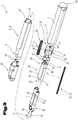
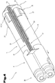
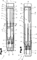
- FIGS 1 to 8 show different views and sections of an injection device 1, which can also be designated as an autoinjector.
- Such autoinjectors serve to administer at least one medication to a person 2 or a living creature, wherein the administration takes place automatically and therefore without contributory action by the operator.
- Such injection devices 1 are secured, in their storage setting, against unintentional triggering, wherein the triggering or actuation can only take place by deliberate release or disengagement of a securing device 14, described hereinafter. If release has been effected, triggering or actuation can follow, as a result of which the injection device 1 is automatically moved into an injection position, and, in this position, the medication or medications stored in the device are administered.
- injection device 1 In some application situations it may be necessary for several medications to be held separately from one another in the injection device 1, without them coming in contact with one another before the administration. It is for such a purpose that the injection device 1 described hereinafter is provided. It is intended that at least two medications should be held ready so that the medicaments can then be administered to the patient 2 simultaneously in one administration procedure.
- the injection device 1 comprises a distal end section 3, which in use is directed towards the patient 2, and a proximal end section 4, which faces away from the patient.
- the designations front and rear are used, and in this context 'front' is assigned to the patient facing or distal end section 3 and 'rear' to the proximal end section 4.
- the injection device 1 therefore comprises a carrying housing 5, which is configured in the form of a sleeve and comprises a distal end 6 and a proximal end 7. Also provided is an activation sleeve 8, which surrounds the carrying housing 5 over a predominant part of its longitudinal extension, starting from the proximal end 7 in the direction towards the distal end 6. In this arrangement, the distal end 6 of the carrying housing 5 projects beyond the activation sleeve 8 in the distal direction.
- the activation sleeve 8 is movable relative to the carrying housing 5 in the axial direction, and guided on it. As will be described hereinafter, this relative movement serves for the release and therefore the associated administration of the medication or the medications.
- two carpules 9, 11 are arranged in the carrying housing 5, accommodating the medications which are to be administered in each case but are not designated in greater detail.
- a piston 10, 12 for providing a sealing closure of the carpules 9, 11 in their proximal end regions.
- the carpules 9, 11 are in drive connection with a first drive module 13.
- the at least two carpules 9, 11, seen in cross-section, are arranged next to one another in the carrying housing 5.
- the activation or triggering of the drive module 13 can take place by means of the activation sleeve 8, after release of the securing device 14.
- the securing device 14 holds at least the first drive module 13 securely in its position in relation to the carrying housing 5 until its activation for the injection procedure.
- the cannulas 15, 16 form a needle arrangement 17.
- the needle arrangement, and in particular its cannulas 15, 16, are arranged in front of the respective carpules 9, 11, in the section of the distal end 6.
- Each of the cannulas 15, 16 comprises in turn cannula ends 18, 19, wherein, in the storage setting, both of the cannula ends 18, 19 respectively are also arranged inside the carrying housing 5.
- the proximal ends 19 of the cannulas 15, 16 are arranged in front of the respective carpules 9, 11. The puncture, and therefore the access to the medication, does not take place until the activation of the injection device 1 by the activation sleeve 8.
- a needle protection element 20 In order to cover the distal ends 18 of the cannulas, which project beyond the carrying housing 5 after the administration of the medications, provision can also be made for a needle protection element 20. If the injection device 1 is in the storage setting, the needle protection element 20 is arranged in what is referred to as a release position for the distal ends 18, in which unhindered movement of the cannulas 15, 16 and the subsequent administration can take place. If the administration procedure has begun, and the distal cannula ends 18 are still in the inserted injection position in the patient 2, the needle protection element 20 can be located in a position on the skin or on an item of clothing if the patient 2 is a person.
- a second triggerable or activatable drive module 18 can be provided, which is in drive connection with the needle protection element 20. This therefore makes it possible for the needle protection element 20 to move beyond the distal cannula ends 18 after the injection procedure, projecting from the carrying housing 5 over the distal end 6, into a cover position protecting these ends.
- the drive module 13 can further comprise a drive element 22, which is likewise arranged inside the carrying housing 5.
- the drive element 22 comprises in each case a number of piston rods 23, 24 which is equal to the number of carpules 9, 11.
- the piston rods 23, 24 form a composite structural unit.
- At least one of the piston rods 23, 24 is configured in the form of a hollow cylinder, and is formed as closed at an end region 25 that faces towards the distal end section 3.
- a first drive means 26 of the first drive module 13 is arranged or accommodated in the at least one piston rod 23, 24 configured in the form of a hollow cylinder.
- first drive means 26 it would also be possible to provide an accommodation part 27 on the drive element 22, which, when seen in cross-section, is arranged laterally next to the piston rods 23, 24. This would make possible for a multiple arrangement of first drive means 26 to be provided, with which in each case a first drive means 26 is located both inside at least one of the piston rods 23, 24 as well as inside the accommodation part 27.
- the drive element 22 can further comprise a connection part 28, by means of which the at least two piston rods 23, 24, and, if provided, also the accommodation part 27, are connected to one another to form a structural unit.
- Each of the piston rods 23, 24, and, if provided, also the accommodation part 27, exhibit respective end regions 29, wherein the mutual connection to form a structural unit takes place in the area of said end regions 29.
- the at least two piston rods 23, 24 and, as appropriate, the accommodation part 27 project from this in the distal direction (i.e. towards the 'front' of the device).
- the at least two piston rods 23, 24 and the accommodation part 27 of the drive element 22 are respectively configured in the form of hollow cylinders, and in each case are formed as closed in at first end regions 25 thereof which face towards the distal end section 3.
- the first possibility makes provision for only one of the pistons 10, 12 of a first of the at least two carpules 9, 11 to be coupled to the piston rod 23, 24 allocated to the piston 10, 12, and therefore to be brought into drive connection.
- the other of the at least two carpules 11, 9 is held by means of a holding device 30 at the first of the at least two carpules 9, 11.
- the other piston rod 24, 23, which is not coupled, serves only to drive forward the carpule 11 and the piston 12 arranged within it.
- each of the pistons 10, 12 is coupled to the piston rods 23, 24 allocated respectively to the pistons, and the at least two carpules 9, 11 are held on the drive element 22 independently of one another.
- the carrying housing 5 is subdivided into a first carrying housing part 31 and a rear carrying housing part 32.
- the front carrying housing part 31 delimits a front accommodation space 33 and the rear carrying housing part 32 delimits a rear accommodation space 34.
- the two carrying housing parts 31, 32 are connected to one another in a connection section 35 in the axial direction, in two different longitudinal positions, in a first connection setting and a second connection setting. This can be done by means of a coupling device 36, not represented in any greater detail. Accordingly, the carrying housing parts 31, 32 in the first connection setting exhibit a greater longitudinal extension in relation to the second connection setting.
- the front carrying house part 31 exhibits a longitudinal extension in the axial direction, which is selected in a value range with a value with a lower limit of 60% and a value with an upper limit of 95% related to the overall longitudinal extension of the two carrying housing parts 31, 32, in their second connection setting. It has, however, also transpired that a value range is favourable with which a value is selected with a lower limit of 70% and a value with an upper limit of 85% related to the overall longitudinal extension of the two carrying housing parts 31, 32, in their second connection setting.
- the rear carrying housing part 32 can comprise at least two guide extensions 37 projecting in the distal direction. It would also be possible, however, for the guide extensions 37 to be provided either only on the front carrying housing part 31 or also on reciprocal sides. The guide extensions 37 are supported at the front carrying housing part 31 and/or at the rear carrying housing part 32, lying in contact with them.
- the distal end 7 of the carrying housing 5, in particular the distal end 7 of the front carrying housing part 31, to exhibit a number of openings 38, equal to the number of cannulas 15, 16. Since preferably the number of cannulas 15, 16 is selected as equal to the number of carpules 9, 11, this number also corresponds to the number of openings 38.
- a puncturable sealing plug 39 Arranged in each case in the individual openings 38 is a puncturable sealing plug 39, in a sealing position, wherein, by the openings 38, the through passage of the distal cannula ends 18 of the cannulas 15, 16 is made possible. During the administration procedure, the sealing plugs 39 are also punctured by the cannulas 15, 16.
- a sealing element 40 is also provided, which is formed such as to run continuously over the circumference.
- the sealing element 40 comprises at its distal end section, facing towards the front carrying housing part 31, a sealing attachment 41, running continuously over the entire circumference.
- the preferably flange-shaped sealing attachment 41 can further be configured such that it projects between mutually facing face surfaces 42, 43 of the two carrying housing parts 31, 32; see Fig. 8 .
- a circumferential gap is also formed between the mutually facing face surfaces of the two carrying housing parts 31, 32, into which gap the sealing attachment 41 can also project.
- the gap width is to be selected as sufficiently large for the gap not to be completely closed by the sealing attachment 41 located in it.
- the sealing attachment 41 in the first connection setting of the two carrying housing parts 31, to be arranged at a distance from the face surface 42 of the front carrying housing part 31.
- the sealing attachment 41 is in sealing contact on the face surface 42 of the front carrying housing part 31.
- the sealing attachment 41 of the sealing element 40 can also be supported on the face surface 43 of the rear carrying housing part 32, facing the front carrying housing part 31.
- the circumferential sealing element 40 can also extend into the rear carrying housing part 32, and be supported lying in contact on its inner surface.
- sealing element 40 in the storage setting of the device, and with the carrying housing parts 31, 32 being in the second connection setting, is also in sealing contact over the full circumference on the drive element 22, arranged in the interior of the housing parts.
- a circumferential support of the sealing element 40 is preferably also to be provided on the inner surface of the rear carrying housing part 32.
- at least the front accommodation space 33, in the storage setting of the device, is to be completely sealed against the outside surrounding environment by means of the sealing element 40.
- the sealing contact of the sealing element 40 is to be applied in particular at the outer circumference of the connection part 28 of the drive element.
- the securing device 14 comprises at least one retention hook 44, and preferably a plurality thereof, which is or are arranged with at least one retention hook 44 on the drive element 22.
- the connection part 28 of the drive element 22 comprises in this context a face wall, aligned preferably in the perpendicular direction in relation to a longitudinal axis 45 of the injection device 1, from which wall the at least one retention hook 44 is arranged projecting in the proximal direction.
- the carrying housing 5, in particular the rear carrying housing part 32 can comprise at its distal end a transverse wall 46, with a latch engagement cut-out opening 47 arranged in it.
- the at least one retention hook 44 in the secure setting as well as in the storage setting, can be held in the latch engagement cut-out opening 47 of the transverse wall 46.
- the at least one retention hook 44 engages behind the transverse wall 46, on its side facing the proximal end section 4.
- the first drive means 26 is supported on the one hand at the rear carrying housing part 32, and in the accommodation part 27, imposing preliminary tension on it. If the securing device 14 is released, the drive element 22 is displaced in the direction towards the distal end 6 or the distal end section 3.
- the securing device 14 can further comprise a securing cap 48, with a securing pin 49, arranged in the proximal end section 4 of the injection device 1.
- a securing pin 49 By means of this securing pin 49, the at least one retention hook 44, in the storage setting, is held in a latched setting at the carrying housing 5. In order to release or free the at least one retention hook 44, it is first to be freed by the securing pin 49.
- the sleeve comprises in its proximal end region a closure wall 50.
- a triggering means 51 which, in this exemplary embodiment, is configured as a trigger opening.
- the triggering means 51 is aligned in the axial direction flush in relation to the latch engagement cut-out opening 47 arranged in the transverse wall 46 of the carrying housing 5, in particular of the rear carrying housing part 32.
- the needle protection element 20 is in drive connection with the second drive module 21; see Fig. 4 .
- the second drive module 21 comprises at least one second drive means 52, which is arranged outside the carrying housing 5, in particular the two carrying housing parts 31, 32, and inside the activation sleeve 8.
- the second drive means 52 extends in the axial direction between the needle protection element 20 and the proximal end of the carrying housing 5, in particular the rear carrying housing part 32. So, for example, the face wall of the connection part 28 can form a stop for the second drive means 52.
- first drive means 26 and the second drive means 52 are in each case formed by a pressure spring configured as a helical spring. This allows for recourse to be made to standard components. It therefore becomes possible to select a slim configuration of the second drive means 52. Accordingly, the second drive means 52, configured as a helical spring, can be arranged on the side of the piston rods 23, in cross-section located opposite the accommodation part 27 of the drive element 22, between the carrying housing 5 and the activation sleeve 8.
- the drive means can be guided in its longitudinal extension at least in part by means of guide elements 53.
- the guide elements 53 can be arranged on an outer side of the carrying housing 5, in particular of the front carrying housing part 31, and can be formed by webs or ribs.
- the needle protection element 20 can be held locked in its cover setting in the proximal direction as well as in the axial direction relative in relation to the carrying housing 5 by means of a locking device, not represented in greater detail.
- the axial adjustment movement carried out by the activation sleeve 8 in relation to the carrying housing 5 has the effect of the simultaneous release of both the first drive module 12 as well as of the second drive module 21.
- the configuration of the injection device 1 described hereinbefore, in particular of the autoinjector, in a number of component groups corresponds to that configuration such as in WO 2009/152542 A1 , by a forerunner company of the present Applicants. Accordingly, for the configuration of the needle arrangement 17, and for the guiding and locking engagement of the needle protection element 20 and of the carpules 9, 11, reference is made to the disclosure contained in the WO-A1.
Landscapes
- Health & Medical Sciences (AREA)
- Engineering & Computer Science (AREA)
- Hematology (AREA)
- Anesthesiology (AREA)
- Biomedical Technology (AREA)
- Heart & Thoracic Surgery (AREA)
- Vascular Medicine (AREA)
- Life Sciences & Earth Sciences (AREA)
- Animal Behavior & Ethology (AREA)
- General Health & Medical Sciences (AREA)
- Public Health (AREA)
- Veterinary Medicine (AREA)
- Environmental & Geological Engineering (AREA)
- Infusion, Injection, And Reservoir Apparatuses (AREA)
- Medicines Containing Antibodies Or Antigens For Use As Internal Diagnostic Agents (AREA)
Claims (15)
- Autoinjektor (1), der für die gleichzeitige Verabreichung von mindestens zwei Medikamenten konfiguriert ist und automatisch von einer Lagerungseinstellung in eine Injektionsposition bewegt werden kann, und wobei der Autoinjektor (1), der einen distalen Endabschnitt (3), der beim Gebrauch auf einen Patienten (2) gerichtet ist, und einen proximalen Endabschnitt (4) aufweist, der davon abgewandt ist, Folgendes umfasst:ein Traggehäuse (5), wobei das Traggehäuse (5) in Form einer Hülse konfiguriert ist und ein distales Ende (6) und ein proximales Ende (7) aufweist;eine Aktivierungshülse (8), die einen überwiegenden Teil einer longitudinalen Erstreckung des Traggehäuses (5) umgibt und vom proximalen Ende (7) in Richtung auf das distale Ende (6) beginnt, so dass das distale Ende (6) des Traggehäuses (5) über die Aktivierungshülse (8) hinaus vorsteht, wobei die Aktivierungshülse (8) in Bezug auf das Traggehäuse (5) in einer axialen Richtung beweglich ist;eine erste Karpule (9), die in dem Traggehäuse (5) positioniert ist, wobei die erste Karpule (9) einen darin angeordneten Kolben (10), der in der axialen Richtung justierbar ist, und ein in der ersten Karpule (9) aufgenommenes Medikament zur Verabreichung während einer Injektionsprozedur enthält;eine zweite Karpule (11), die in dem Traggehäuse (5) positioniert ist, wobei die zweite Karpule (11) einen darin angeordneten Kolben (12), der in der axialen Richtung justierbar ist, und ein in der zweiten Karpule (11) aufgenommenes Medikament zur Verabreichung während der Injektionsprozedur aufweist, und wobei die erste Karpule und die zweite Karpule (9, 11) im Querschnitt gesehen nebeneinander in dem Traggehäuse (5) angeordnet sind;ein erstes Antriebsmodul (13) mit einem ersten Antriebsmittel (26), wobei das erste Antriebsmodul (13) in Antriebsverbindung mit der ersten Karpule und/oder der zweiten Karpule (9, 11) steht und durch die Aktivierungshülse (8) aktiviert werden kann;eine Sicherungsvorrichtung (14) zum Sichern des ersten Antriebsmoduls (13) in Position relativ zum Traggehäuse (5) bis zur Aktivierung des ersten Antriebsmoduls für die Injektionsprozedur; undeine Nadelanordnung (17) mit mindestens einer Kanüle (15, 16), wobei in der Lagerungseinstellung des Autoinjektors (1) die Nadelanordnung (17) vor der ersten Karpule und/oder der zweiten Karpule (9, 11) im distalen Endabschnitt (3) so positioniert ist, dass beide Enden (18, 19) der mindestens einen Kanüle (15, 16) innerhalb des Traggehäuses (5) angeordnet sind;ein Nadelschutzelement (20), wobei in der Lagerungseinstellung des Autoinjektors das Nadelschutzelement (20) von einer Freigabeposition in eine Abdeckposition bewegbar ist, in der ein Ende (18) der mindestens einen Kanüle (15, 16) abgedeckt ist, und wobei das Kanülenende nach der Injektionsprozedur über das distale Ende (6) des Traggehäuses (5) hinaus vorsteht;ein zweites aktivierbares Antriebsmodul (21) mit einem zweiten Antriebsmittel (52), wobei das zweite Antriebsmodul (21) zum Bewegen des Nadelschutzelements (20) von einer nicht aktiven Position in die Abdeckposition ausgelegt ist; undwobei das erste Antriebsmodul (13) ferner ein Antriebselement (22) aufweist, das innerhalb des Traggehäuses (5) angeordnet ist, wobei das Antriebselement (22) eine erste Kolbenstange und eine zweite Kolbenstange (23, 24) aufweist, die eine Verbundstruktureinheit bilden;wobei die erste Kolbenstange und/oder die zweite Kolbenstange (23, 24) ein Hohlzylinder ist/sind, der an einem ersten Endabschnitt (25), der dem distalen Endabschnitt (3) zugewandt ist, geschlossen ist;wobei das erste Antriebsmittel (26) im Hohlzylinder der ersten und/oder der zweiten Kolbenstange (23, 24) angeordnet ist.
- Autoinjektor (1) nach Anspruch 1, dadurch gekennzeichnet, dass die erste und zweite Karpule (9, 11) in einem jeweiligen Fall jeweils vor ihrer eigenen Kanüle (15, 16) angeordnet sind.
- Autoinjektor (1) nach einem der vorherigen Ansprüche, dadurch gekennzeichnet, dass nur einer der Kolben (10) einer ersten Karpule der mindestens zwei Karpulen (9) mit der dem Kolben (10) zugeordneten Kolbenstange (23) gekoppelt ist, und wobei die andere der mindestens zwei Karpulen (11) mittels einer Haltevorrichtung (30) an der ersten Karpule (9) gehalten wird.
- Autoinjektor (1) nach Anspruch 1, dadurch gekennzeichnet, dass der erste und zweite Kolben (10, 12) jeweils mit der ersten bzw. zweiten Kolbenstange (23, 24) gekoppelt sind und die erste und zweite Karpule (9, 11) unabhängig voneinander am Antriebselement (22) gehalten werden.
- Autoinjektor (1) nach einem der vorherigen Ansprüche, dadurch gekennzeichnet, dass entweder:(a) das Traggehäuse (5) ein vorderes Traggehäuseteil (31) mit einem vorderen Aufnahmeraum (33) und ein hinteres Traggehäuseteil (32) mit einem hinteren Aufnahmeraum (34) aufweist und die beiden Traggehäuseteile (31, 32) in einem Verbindungsabschnitt (35) in axialer Richtung in zwei unterschiedlichen longitudinalen Positionen in einer ersten Verbindungseinstellung und einer zweiten Verbindungseinstellung miteinander verbunden werden können; oder(b) das Traggehäuse (5) ein vorderes Traggehäuseteil (31) mit einem vorderen Aufnahmeraum (33) und ein hinteres Traggehäuseteil (32) mit einem hinteren Aufnahmeraum (34) aufweist und die beiden Traggehäuseteile (31, 32) in einem Verbindungsabschnitt (35) in axialer Richtung in zwei unterschiedlichen longitudinalen Positionen in einer ersten Verbindungseinstellung und einer zweiten Verbindungseinstellung miteinander verbunden werden können; wobei die beiden Traggehäuseteile (31, 32) in dem Verbindungsabschnitt (35) mittels einer Kopplungsvorrichtung (36) miteinander verbunden werden können.
- Autoinjektor (1) nach Anspruch 5, dadurch gekennzeichnet, dass das hintere Traggehäuseteil (32) mindestens zwei in distaler Richtung vorstehende Führungsverlängerungen (37) aufweist, wobei die Führungsverlängerungen (37) dadurch gelagert sind, dass sie in Kontakt mit dem vorderen Traggehäuseteil (31) liegen.
- Autoinjektor (1) nach Anspruch 5 oder 6, dadurch gekennzeichnet, dass die Traggehäuseteile (31, 32) in der ersten Verbindungseinstellung eine größere longitudinale Erstreckung in Bezug auf die zweite Verbindungseinstellung aufweisen.
- Autoinjektor (1) nach einem der Ansprüche 5 bis 7, dadurch gekennzeichnet, dass das vordere Traggehäuseteil (31) eine longitudinale Erstreckung in axialer Richtung aufweist, die in einem Wertebereich mit einer Untergrenze von 60% und einer Obergrenze von 95%, insbesondere mit einer Untergrenze von 70% und einer Obergrenze von 85%, bezogen auf die gesamte longitudinale Erstreckung der beiden Traggehäuseteile (31) in der zweiten Verbindungseinstellung gewählt wird.
- Autoinjektor (1) nach einem der vorherigen Ansprüche, dadurch gekennzeichnet, dass das distale Ende (6) des Traggehäuses (5), insbesondere das distale Ende (6) des vorderen Traggehäuseteils (31), eine Anzahl von Öffnungen (38) aufweist, die der Anzahl der Kanülen (15, 16) entspricht, wobei die Öffnungen (38) den Durchtritt der distalen Enden (18) der Kanülen (15, 16) ermöglichen und in jedem Fall ein durchstechbarer Verschlussstopfen (39) in den Öffnungen (38) in einer Abdichtposition angeordnet ist.
- Autoinjektor (1) nach einem der vorherigen Ansprüche, dadurch gekennzeichnet, dass ein Dichtungselement (40) vorgesehen ist, wobei das Dichtungselement (40) zwischen dem vorderen Traggehäuseteil (31) und dem hinteren Traggehäuseteil (32) angeordnet und über den Umfang durchgehend verlaufend ausgebildet ist.
- Autoinjektor (1) nach Anspruch 10, dadurch gekennzeichnet, dass entweder(a) das Dichtungselement (40) an dem dem vorderen Traggehäuseteil (31) zugewandten distalen Endabschnitt einen Dichtungsansatz (41) aufweist, wobei in der ersten Verbindungseinstellung der beiden Traggehäuseteile (31) der Dichtungsansatz (41) in einem Abstand von einer Stirnfläche (42) des vorderen Traggehäuseteils (31) angeordnet ist und in der zweiten Verbindungseinstellung der beiden Traggehäuseteile (31, 10, 32) der Dichtungsansatz (41) an der Stirnfläche (42) des vorderen Traggehäuseteils (31) in Dichtungskontakt steht; oder(b) das Dichtungselement (40) an dem dem vorderen Traggehäuseteil (31) zugewandten distalen Endabschnitt einen Dichtungsansatz (41) aufweist, wobei in der ersten Verbindungseinstellung der beiden Traggehäuseteile (31) der Dichtungsansatz (41) in einem Abstand von einer Stirnfläche (42) des vorderen Traggehäuseteils (31) angeordnet ist und in der zweiten Verbindungseinstellung der beiden Traggehäuseteile (31, 32) der Dichtungsansatz (41) an der Stirnfläche (42) des vorderen Traggehäuseteils (31) in Dichtungskontakt steht; wobei der Dichtungsansatz (41) des Dichtungselements (40) auf einer Stirnfläche (43) des hinteren Traggehäuseteils (32) gelagert ist, die dem vorderen Traggehäuseteil (31) zugewandt ist, und dass sich das Dichtungselement (40) in Kontakt mit dem hinteren Traggehäuseteil (32) erstreckt.
- Autoinjektor (1) nach Anspruch 10 oder 11, dadurch gekennzeichnet, dass das Dichtungselement (40) in der Lagerungseinstellung des Autoinjektors und mit den Traggehäuseteilen (31, 32) in der zweiten Verbindungseinstellung sowohl am hinteren Traggehäuseteil (32) als auch an dem innerhalb des Gehäuseteils angeordneten Antriebselement (22), insbesondere mit dessen Verbindungsteil (28) des ersten Antriebsmoduls (13), über den gesamten Umfang in Dichtungskontakt steht.
- Autoinjektor (1) nach einem der vorherigen Ansprüche, dadurch gekennzeichnet, dass das Traggehäuse (5), insbesondere das hintere Traggehäuseteil (32), an seinem distalen Ende eine Querwand (46) aufweist, in der eine Rasteingriffsaussparung (47) angeordnet ist.
- Autoinjektor (1) nach einem der vorherigen Ansprüche, dadurch gekennzeichnet, dass die Sicherungsvorrichtung (14) eines der Folgenden umfasst, entweder:(a) mindestens einen Haltehaken (44), wobei der mindestens eine Haltehaken (44) an dem Antriebselement (22), insbesondere dessen Verbindungsteil (28), angeordnet ist, und wobei in der Lagerungseinstellung des Autoinjektors der mindestens eine Haltehaken (44) in der Rasteingriffsaussparung (47) der Querwand (46) gehalten wird; und/oder(b) eine Sicherungskappe (48) mit einem Sicherungsstift (49), die im distalen Endabschnitt (3) angeordnet ist, und wobei mittels des Sicherungsstiftes (49) der mindestens eine Haltehaken (44) in der Lagerungseinstellung der Vorrichtung in einer Rasteingriffseinstellung gehalten wird.
- Autoinjektor (1) nach einem der vorherigen Ansprüche, dadurch gekennzeichnet, dass der proximale Endbereich der Aktivierungshülse (8) eine Verschlusswand (50) aufweist, an welcher Verschlusswand (50) ein Auslösemittel (51), insbesondere eine Auslöseöffnung, angeordnet ist, wobei das Auslösemittel (51) in axialer Richtung bündig in Bezug auf die Querwand (46) des Traggehäuses (5), insbesondere des hinteren Traggehäuseteils (32), angeordneten Rasteingriffsaussparung (47) ausgerichtet ist.
Priority Applications (1)
| Application Number | Priority Date | Filing Date | Title |
|---|---|---|---|
| EP21207263.1A EP4008379A1 (de) | 2016-10-27 | 2017-10-27 | Injektionsvorrichtung, insbesondere ein autoinjektor, zur gleichzeitigen verabreichung mehrerer medikamente |
Applications Claiming Priority (3)
| Application Number | Priority Date | Filing Date | Title |
|---|---|---|---|
| US201662413557P | 2016-10-27 | 2016-10-27 | |
| ATA50987/2016A AT519383B1 (de) | 2016-10-27 | 2016-10-27 | Injektionsvorrichtung, insbesondere Autoinjektor, zur gleichzeitigen Abgabe von mehreren Medikamenten |
| PCT/EP2017/077651 WO2018078121A1 (en) | 2016-10-27 | 2017-10-27 | Injection device, in particular autoinjector, for the simultaneous administration of several medications |
Related Child Applications (1)
| Application Number | Title | Priority Date | Filing Date |
|---|---|---|---|
| EP21207263.1A Division EP4008379A1 (de) | 2016-10-27 | 2017-10-27 | Injektionsvorrichtung, insbesondere ein autoinjektor, zur gleichzeitigen verabreichung mehrerer medikamente |
Publications (2)
| Publication Number | Publication Date |
|---|---|
| EP3532129A1 EP3532129A1 (de) | 2019-09-04 |
| EP3532129B1 true EP3532129B1 (de) | 2021-01-20 |
Family
ID=62024420
Family Applications (2)
| Application Number | Title | Priority Date | Filing Date |
|---|---|---|---|
| EP17792033.7A Active EP3532129B1 (de) | 2016-10-27 | 2017-10-27 | Injektionsvorrichtung, insbesondere ein autoinjektor, zur gleichzeitigen verabreichung mehrerer medikamente |
| EP21207263.1A Withdrawn EP4008379A1 (de) | 2016-10-27 | 2017-10-27 | Injektionsvorrichtung, insbesondere ein autoinjektor, zur gleichzeitigen verabreichung mehrerer medikamente |
Family Applications After (1)
| Application Number | Title | Priority Date | Filing Date |
|---|---|---|---|
| EP21207263.1A Withdrawn EP4008379A1 (de) | 2016-10-27 | 2017-10-27 | Injektionsvorrichtung, insbesondere ein autoinjektor, zur gleichzeitigen verabreichung mehrerer medikamente |
Country Status (16)
| Country | Link |
|---|---|
| US (2) | US20190262539A1 (de) |
| EP (2) | EP3532129B1 (de) |
| JP (2) | JP7153643B2 (de) |
| KR (2) | KR102528639B1 (de) |
| CN (2) | CN113730730B (de) |
| AT (1) | AT519383B1 (de) |
| AU (2) | AU2017348622B2 (de) |
| CA (1) | CA3040594A1 (de) |
| ES (1) | ES2867881T3 (de) |
| IL (2) | IL266203B (de) |
| MY (1) | MY201251A (de) |
| RU (2) | RU2022101207A (de) |
| SA (1) | SA519401634B1 (de) |
| SG (1) | SG11201903156SA (de) |
| WO (1) | WO2018078121A1 (de) |
| ZA (2) | ZA201903190B (de) |
Families Citing this family (10)
| Publication number | Priority date | Publication date | Assignee | Title |
|---|---|---|---|---|
| EP3274021B1 (de) | 2015-03-24 | 2024-02-14 | Kaleo, Inc. | Vorrichtungen und verfahren zur abgabe eines lyophilisierten medikaments |
| AU2016287571C1 (en) | 2015-06-30 | 2021-12-23 | Kaleo, Inc. | Auto-injectors for administration of a medicament within a prefilled syringe |
| USD866757S1 (en) * | 2016-03-11 | 2019-11-12 | Millennium Pharmaceuticals, Inc. | Autoinjector |
| WO2018119218A1 (en) | 2016-12-23 | 2018-06-28 | Kaleo, Inc. | Medicament delivery device and methods for delivering drugs to infants and children |
| EP3902584A4 (de) | 2018-12-29 | 2022-09-07 | Kaleo, Inc. | Vorrichtungen und verfahren zur abgabe von substanzen in einer vorgefüllten spritze |
| US11167087B2 (en) | 2019-08-09 | 2021-11-09 | Kaleo, Inc. | Devices and methods for delivery of substances within a prefilled syringe |
| US12268847B1 (en) | 2021-02-10 | 2025-04-08 | Kaleo, Inc. | Devices and methods for delivery of substances within a medicament container |
| JPWO2023188563A1 (de) * | 2022-03-28 | 2023-10-05 | ||
| WO2024134928A1 (ja) * | 2022-12-23 | 2024-06-27 | テルモ株式会社 | 薬剤投与具 |
| WO2024256275A1 (en) | 2023-06-12 | 2024-12-19 | Boehringer Ingelheim International Gmbh | Holding device for dispensing devices for substance dispensing of at least one therapeutically and/or diagnostically effective substance |
Family Cites Families (28)
| Publication number | Priority date | Publication date | Assignee | Title |
|---|---|---|---|---|
| FR447368A (fr) | 1912-08-19 | 1912-12-31 | Marcel Mairesse | Injecteur à aiguillons pour la révulsion médicatrice intra-dermique |
| FR1514210A (fr) | 1966-12-26 | 1968-02-23 | Seringue hypodermique automatique | |
| US3572336A (en) | 1968-04-30 | 1971-03-23 | Daniel R Hershberg | Syringe |
| US4226235A (en) | 1979-01-25 | 1980-10-07 | Survival Technology, Inc. | Plural injecting device |
| US4329988A (en) | 1980-12-23 | 1982-05-18 | Survival Technology, Inc. | Plural injection assembly |
| US4578064A (en) | 1983-12-21 | 1986-03-25 | Survival Technology Inc. | Plural dosage automatic injector with improved safety |
| US4832682A (en) | 1984-08-08 | 1989-05-23 | Survival Technology, Inc. | Injection method and apparatus with electrical blood absorbing stimulation |
| US4689042A (en) * | 1985-05-20 | 1987-08-25 | Survival Technology, Inc. | Automatic medicament ingredient mixing and injecting apparatus |
| US5298023A (en) * | 1991-03-08 | 1994-03-29 | Habley Medical Technology Corporation | Multiple pharmaceutical dispenser with accumulator |
| US5423752A (en) * | 1992-07-31 | 1995-06-13 | Habley Medical Technology Corporation | Variable proportion dispenser with cartridge replacement assembly |
| US5378233A (en) * | 1992-11-18 | 1995-01-03 | Habley Medical Technology Corporation | Selected dose pharmaceutical dispenser |
| ZA941881B (en) * | 1993-04-02 | 1995-09-18 | Lilly Co Eli | Manifold medication injection apparatus and method |
| DE10351594A1 (de) * | 2003-11-05 | 2005-06-16 | Tecpharma Licensing Ag | Vorrichtung für die Verabreichung eines injizierbaren Produkts |
| DE102005017477A1 (de) * | 2005-02-18 | 2006-08-31 | Tecpharma Licensing Ag | Feder in einem oder für ein Injektionsgerät |
| WO2008113864A1 (de) | 2007-03-22 | 2008-09-25 | Tecpharma Licensing Ag | Injektionsvorrichtung mit auslösesicherungen |
| AT506690B1 (de) * | 2008-06-16 | 2009-11-15 | Pharma Consult Ges M B H & Co | Injektionsvorrichtung |
| US9131930B2 (en) * | 2009-06-19 | 2015-09-15 | Medmix Systems Ag | Devices for filling a multi-use syringe or single-use syringe |
| EP2438941A1 (de) * | 2010-10-08 | 2012-04-11 | Sanofi-Aventis Deutschland GmbH | Automatischer Injektor mit Torsionsfeder |
| JP5824223B2 (ja) * | 2011-03-24 | 2015-11-25 | テルモ株式会社 | 2連式プレフィルドシリンジ |
| US8695135B2 (en) | 2012-05-16 | 2014-04-15 | Daniel James Berube | Sacrum support pillow |
| US9522235B2 (en) | 2012-05-22 | 2016-12-20 | Kaleo, Inc. | Devices and methods for delivering medicaments from a multi-chamber container |
| EP3738627B1 (de) | 2012-10-17 | 2025-03-19 | Oval Medical Technologies Limited | Automatische arzneimittelabgabevorrichtungen |
| WO2014205604A1 (zh) * | 2013-06-28 | 2014-12-31 | 群康生技股份有限公司 | 注射器 |
| EP3068475B1 (de) * | 2013-11-13 | 2021-12-15 | F. Hoffmann-La Roche AG | Unterstützte manuelle injektorvorrichtungen und -verfahren |
| WO2015118140A1 (en) | 2014-02-10 | 2015-08-13 | Sanofi-Aventis Deutschland Gmbh | Package for a set of at least two components, sheet packaging material and system comprising a package and a set of at least two components |
| US20170165430A1 (en) | 2014-05-28 | 2017-06-15 | Sanofi-Aventis Deutschland Gmbh | Housing for a drug delivery device and drug delivery device |
| TR201905961T4 (tr) * | 2014-05-28 | 2019-05-21 | Sanofi Aventis Deutschland | İki ilaç maddesinin dağıtılmasına yönelik ilaç dağıtım cihazı. |
| US20160144117A1 (en) * | 2014-11-21 | 2016-05-26 | Thomas Chun | Hypodermic syringe that automatically ejects medicament from a needle |
-
2016
- 2016-10-27 AT ATA50987/2016A patent/AT519383B1/de not_active IP Right Cessation
-
2017
- 2017-10-27 MY MYPI2019001778A patent/MY201251A/en unknown
- 2017-10-27 SG SG11201903156SA patent/SG11201903156SA/en unknown
- 2017-10-27 KR KR1020197015059A patent/KR102528639B1/ko active Active
- 2017-10-27 CN CN202110967970.9A patent/CN113730730B/zh not_active Expired - Fee Related
- 2017-10-27 JP JP2019522397A patent/JP7153643B2/ja active Active
- 2017-10-27 US US16/345,823 patent/US20190262539A1/en not_active Abandoned
- 2017-10-27 EP EP17792033.7A patent/EP3532129B1/de active Active
- 2017-10-27 CN CN201780066659.9A patent/CN110035784A/zh active Pending
- 2017-10-27 RU RU2022101207A patent/RU2022101207A/ru unknown
- 2017-10-27 CA CA3040594A patent/CA3040594A1/en active Pending
- 2017-10-27 AU AU2017348622A patent/AU2017348622B2/en not_active Ceased
- 2017-10-27 RU RU2019113034A patent/RU2764869C2/ru active
- 2017-10-27 EP EP21207263.1A patent/EP4008379A1/de not_active Withdrawn
- 2017-10-27 ES ES17792033T patent/ES2867881T3/es active Active
- 2017-10-27 KR KR1020237014644A patent/KR20230065368A/ko active Pending
- 2017-10-27 WO PCT/EP2017/077651 patent/WO2018078121A1/en not_active Ceased
-
2019
- 2019-04-22 SA SA519401634A patent/SA519401634B1/ar unknown
- 2019-04-23 IL IL266203A patent/IL266203B/en unknown
- 2019-05-21 ZA ZA2019/03190A patent/ZA201903190B/en unknown
-
2021
- 2021-01-25 ZA ZA2021/00502A patent/ZA202100502B/en unknown
- 2021-10-26 US US17/510,888 patent/US11752267B2/en active Active
-
2022
- 2022-03-20 IL IL291521A patent/IL291521B2/en unknown
- 2022-10-03 JP JP2022159484A patent/JP7486277B2/ja active Active
-
2023
- 2023-05-01 AU AU2023202662A patent/AU2023202662A1/en not_active Abandoned
Non-Patent Citations (1)
| Title |
|---|
| None * |
Also Published As
Similar Documents
| Publication | Publication Date | Title |
|---|---|---|
| US11752267B2 (en) | Injection device, in particular autoinjector, for the simultaneous administration of several medications | |
| DE60225540T2 (de) | Sicherheitsschildsystem für vorgefüllte spritzen | |
| DE69830261T2 (de) | Spritzenschutz | |
| AU2009260162B2 (en) | Injection device | |
| DE69726531T2 (de) | Verriegelbare Schutzhülse für vorgefüllte Spritze | |
| JP4937139B2 (ja) | 医療用針のための安全装置 | |
| BR112018005045B1 (pt) | Dispositivo de injeção | |
| BR112014005036B1 (pt) | dispositivo de injeção | |
| JPH03139363A (ja) | 注射針の安全防護装置 | |
| JP6300940B2 (ja) | 薬剤投与装置 | |
| NZ793836A (en) | Injection device, in particular autoinjector, for the simultaneous administration of several medications | |
| ITBS20070024A1 (it) | Strumento per iniezioni con ago retraibile dopo l'uso | |
| HK40059119A (en) | Injection device, in particular autoinjector, for the simultaneous administration of several medications | |
| HK40010235A (en) | Injection device, in particular autoinjector, for the simultaneous administration of several medications | |
| EP1293223A1 (de) | Behälter zur nadellosen Injektion von medizinisch wirksamen Substanzen | |
| EP2559449B1 (de) | Sicherheitsspritze | |
| CA2971263A1 (en) | Injector for drugs | |
| DE202011107268U1 (de) | Sicherheits-Injektionsspritze |
Legal Events
| Date | Code | Title | Description |
|---|---|---|---|
| STAA | Information on the status of an ep patent application or granted ep patent |
Free format text: STATUS: UNKNOWN |
|
| STAA | Information on the status of an ep patent application or granted ep patent |
Free format text: STATUS: THE INTERNATIONAL PUBLICATION HAS BEEN MADE |
|
| PUAI | Public reference made under article 153(3) epc to a published international application that has entered the european phase |
Free format text: ORIGINAL CODE: 0009012 |
|
| STAA | Information on the status of an ep patent application or granted ep patent |
Free format text: STATUS: REQUEST FOR EXAMINATION WAS MADE |
|
| 17P | Request for examination filed |
Effective date: 20190522 |
|
| AK | Designated contracting states |
Kind code of ref document: A1 Designated state(s): AL AT BE BG CH CY CZ DE DK EE ES FI FR GB GR HR HU IE IS IT LI LT LU LV MC MK MT NL NO PL PT RO RS SE SI SK SM TR |
|
| AX | Request for extension of the european patent |
Extension state: BA ME |
|
| DAV | Request for validation of the european patent (deleted) | ||
| DAX | Request for extension of the european patent (deleted) | ||
| STAA | Information on the status of an ep patent application or granted ep patent |
Free format text: STATUS: EXAMINATION IS IN PROGRESS |
|
| 17Q | First examination report despatched |
Effective date: 20200220 |
|
| GRAP | Despatch of communication of intention to grant a patent |
Free format text: ORIGINAL CODE: EPIDOSNIGR1 |
|
| STAA | Information on the status of an ep patent application or granted ep patent |
Free format text: STATUS: GRANT OF PATENT IS INTENDED |
|
| REG | Reference to a national code |
Ref country code: HK Ref legal event code: DE Ref document number: 40013321 Country of ref document: HK |
|
| INTG | Intention to grant announced |
Effective date: 20200805 |
|
| GRAS | Grant fee paid |
Free format text: ORIGINAL CODE: EPIDOSNIGR3 |
|
| GRAA | (expected) grant |
Free format text: ORIGINAL CODE: 0009210 |
|
| STAA | Information on the status of an ep patent application or granted ep patent |
Free format text: STATUS: THE PATENT HAS BEEN GRANTED |
|
| AK | Designated contracting states |
Kind code of ref document: B1 Designated state(s): AL AT BE BG CH CY CZ DE DK EE ES FI FR GB GR HR HU IE IS IT LI LT LU LV MC MK MT NL NO PL PT RO RS SE SI SK SM TR |
|
| REG | Reference to a national code |
Ref country code: GB Ref legal event code: FG4D |
|
| REG | Reference to a national code |
Ref country code: CH Ref legal event code: EP |
|
| REG | Reference to a national code |
Ref country code: AT Ref legal event code: REF Ref document number: 1355814 Country of ref document: AT Kind code of ref document: T Effective date: 20210215 |
|
| REG | Reference to a national code |
Ref country code: IE Ref legal event code: FG4D |
|
| REG | Reference to a national code |
Ref country code: DE Ref legal event code: R096 Ref document number: 602017031741 Country of ref document: DE |
|
| REG | Reference to a national code |
Ref country code: CH Ref legal event code: NV Representative=s name: ISLER AND PEDRAZZINI AG, CH |
|
| REG | Reference to a national code |
Ref country code: NL Ref legal event code: MP Effective date: 20210120 |
|
| REG | Reference to a national code |
Ref country code: LT Ref legal event code: MG9D |
|
| REG | Reference to a national code |
Ref country code: AT Ref legal event code: MK05 Ref document number: 1355814 Country of ref document: AT Kind code of ref document: T Effective date: 20210120 |
|
| PG25 | Lapsed in a contracting state [announced via postgrant information from national office to epo] |
Ref country code: BG Free format text: LAPSE BECAUSE OF FAILURE TO SUBMIT A TRANSLATION OF THE DESCRIPTION OR TO PAY THE FEE WITHIN THE PRESCRIBED TIME-LIMIT Effective date: 20210420 Ref country code: LT Free format text: LAPSE BECAUSE OF FAILURE TO SUBMIT A TRANSLATION OF THE DESCRIPTION OR TO PAY THE FEE WITHIN THE PRESCRIBED TIME-LIMIT Effective date: 20210120 Ref country code: HR Free format text: LAPSE BECAUSE OF FAILURE TO SUBMIT A TRANSLATION OF THE DESCRIPTION OR TO PAY THE FEE WITHIN THE PRESCRIBED TIME-LIMIT Effective date: 20210120 Ref country code: GR Free format text: LAPSE BECAUSE OF FAILURE TO SUBMIT A TRANSLATION OF THE DESCRIPTION OR TO PAY THE FEE WITHIN THE PRESCRIBED TIME-LIMIT Effective date: 20210421 Ref country code: FI Free format text: LAPSE BECAUSE OF FAILURE TO SUBMIT A TRANSLATION OF THE DESCRIPTION OR TO PAY THE FEE WITHIN THE PRESCRIBED TIME-LIMIT Effective date: 20210120 Ref country code: PT Free format text: LAPSE BECAUSE OF FAILURE TO SUBMIT A TRANSLATION OF THE DESCRIPTION OR TO PAY THE FEE WITHIN THE PRESCRIBED TIME-LIMIT Effective date: 20210520 Ref country code: NO Free format text: LAPSE BECAUSE OF FAILURE TO SUBMIT A TRANSLATION OF THE DESCRIPTION OR TO PAY THE FEE WITHIN THE PRESCRIBED TIME-LIMIT Effective date: 20210420 |
|
| PG25 | Lapsed in a contracting state [announced via postgrant information from national office to epo] |
Ref country code: SE Free format text: LAPSE BECAUSE OF FAILURE TO SUBMIT A TRANSLATION OF THE DESCRIPTION OR TO PAY THE FEE WITHIN THE PRESCRIBED TIME-LIMIT Effective date: 20210120 Ref country code: RS Free format text: LAPSE BECAUSE OF FAILURE TO SUBMIT A TRANSLATION OF THE DESCRIPTION OR TO PAY THE FEE WITHIN THE PRESCRIBED TIME-LIMIT Effective date: 20210120 Ref country code: LV Free format text: LAPSE BECAUSE OF FAILURE TO SUBMIT A TRANSLATION OF THE DESCRIPTION OR TO PAY THE FEE WITHIN THE PRESCRIBED TIME-LIMIT Effective date: 20210120 Ref country code: PL Free format text: LAPSE BECAUSE OF FAILURE TO SUBMIT A TRANSLATION OF THE DESCRIPTION OR TO PAY THE FEE WITHIN THE PRESCRIBED TIME-LIMIT Effective date: 20210120 Ref country code: AT Free format text: LAPSE BECAUSE OF FAILURE TO SUBMIT A TRANSLATION OF THE DESCRIPTION OR TO PAY THE FEE WITHIN THE PRESCRIBED TIME-LIMIT Effective date: 20210120 |
|
| PG25 | Lapsed in a contracting state [announced via postgrant information from national office to epo] |
Ref country code: IS Free format text: LAPSE BECAUSE OF FAILURE TO SUBMIT A TRANSLATION OF THE DESCRIPTION OR TO PAY THE FEE WITHIN THE PRESCRIBED TIME-LIMIT Effective date: 20210520 |
|
| REG | Reference to a national code |
Ref country code: DE Ref legal event code: R097 Ref document number: 602017031741 Country of ref document: DE Ref country code: ES Ref legal event code: FG2A Ref document number: 2867881 Country of ref document: ES Kind code of ref document: T3 Effective date: 20211021 |
|
| PG25 | Lapsed in a contracting state [announced via postgrant information from national office to epo] |
Ref country code: SM Free format text: LAPSE BECAUSE OF FAILURE TO SUBMIT A TRANSLATION OF THE DESCRIPTION OR TO PAY THE FEE WITHIN THE PRESCRIBED TIME-LIMIT Effective date: 20210120 Ref country code: EE Free format text: LAPSE BECAUSE OF FAILURE TO SUBMIT A TRANSLATION OF THE DESCRIPTION OR TO PAY THE FEE WITHIN THE PRESCRIBED TIME-LIMIT Effective date: 20210120 Ref country code: CZ Free format text: LAPSE BECAUSE OF FAILURE TO SUBMIT A TRANSLATION OF THE DESCRIPTION OR TO PAY THE FEE WITHIN THE PRESCRIBED TIME-LIMIT Effective date: 20210120 |
|
| PLBE | No opposition filed within time limit |
Free format text: ORIGINAL CODE: 0009261 |
|
| STAA | Information on the status of an ep patent application or granted ep patent |
Free format text: STATUS: NO OPPOSITION FILED WITHIN TIME LIMIT |
|
| PG25 | Lapsed in a contracting state [announced via postgrant information from national office to epo] |
Ref country code: RO Free format text: LAPSE BECAUSE OF FAILURE TO SUBMIT A TRANSLATION OF THE DESCRIPTION OR TO PAY THE FEE WITHIN THE PRESCRIBED TIME-LIMIT Effective date: 20210120 Ref country code: SK Free format text: LAPSE BECAUSE OF FAILURE TO SUBMIT A TRANSLATION OF THE DESCRIPTION OR TO PAY THE FEE WITHIN THE PRESCRIBED TIME-LIMIT Effective date: 20210120 Ref country code: DK Free format text: LAPSE BECAUSE OF FAILURE TO SUBMIT A TRANSLATION OF THE DESCRIPTION OR TO PAY THE FEE WITHIN THE PRESCRIBED TIME-LIMIT Effective date: 20210120 |
|
| 26N | No opposition filed |
Effective date: 20211021 |
|
| PG25 | Lapsed in a contracting state [announced via postgrant information from national office to epo] |
Ref country code: AL Free format text: LAPSE BECAUSE OF FAILURE TO SUBMIT A TRANSLATION OF THE DESCRIPTION OR TO PAY THE FEE WITHIN THE PRESCRIBED TIME-LIMIT Effective date: 20210120 |
|
| PG25 | Lapsed in a contracting state [announced via postgrant information from national office to epo] |
Ref country code: SI Free format text: LAPSE BECAUSE OF FAILURE TO SUBMIT A TRANSLATION OF THE DESCRIPTION OR TO PAY THE FEE WITHIN THE PRESCRIBED TIME-LIMIT Effective date: 20210120 |
|
| PG25 | Lapsed in a contracting state [announced via postgrant information from national office to epo] |
Ref country code: IS Free format text: LAPSE BECAUSE OF FAILURE TO SUBMIT A TRANSLATION OF THE DESCRIPTION OR TO PAY THE FEE WITHIN THE PRESCRIBED TIME-LIMIT Effective date: 20210520 |
|
| REG | Reference to a national code |
Ref country code: BE Ref legal event code: MM Effective date: 20211031 |
|
| PG25 | Lapsed in a contracting state [announced via postgrant information from national office to epo] |
Ref country code: MC Free format text: LAPSE BECAUSE OF FAILURE TO SUBMIT A TRANSLATION OF THE DESCRIPTION OR TO PAY THE FEE WITHIN THE PRESCRIBED TIME-LIMIT Effective date: 20210120 |
|
| PG25 | Lapsed in a contracting state [announced via postgrant information from national office to epo] |
Ref country code: LU Free format text: LAPSE BECAUSE OF NON-PAYMENT OF DUE FEES Effective date: 20211027 Ref country code: BE Free format text: LAPSE BECAUSE OF NON-PAYMENT OF DUE FEES Effective date: 20211031 |
|
| PG25 | Lapsed in a contracting state [announced via postgrant information from national office to epo] |
Ref country code: IE Free format text: LAPSE BECAUSE OF NON-PAYMENT OF DUE FEES Effective date: 20211027 |
|
| PG25 | Lapsed in a contracting state [announced via postgrant information from national office to epo] |
Ref country code: NL Free format text: LAPSE BECAUSE OF NON-PAYMENT OF DUE FEES Effective date: 20210120 Ref country code: CY Free format text: LAPSE BECAUSE OF FAILURE TO SUBMIT A TRANSLATION OF THE DESCRIPTION OR TO PAY THE FEE WITHIN THE PRESCRIBED TIME-LIMIT Effective date: 20210120 |
|
| P01 | Opt-out of the competence of the unified patent court (upc) registered |
Effective date: 20230602 |
|
| PG25 | Lapsed in a contracting state [announced via postgrant information from national office to epo] |
Ref country code: HU Free format text: LAPSE BECAUSE OF FAILURE TO SUBMIT A TRANSLATION OF THE DESCRIPTION OR TO PAY THE FEE WITHIN THE PRESCRIBED TIME-LIMIT; INVALID AB INITIO Effective date: 20171027 |
|
| PGFP | Annual fee paid to national office [announced via postgrant information from national office to epo] |
Ref country code: IT Payment date: 20230913 Year of fee payment: 7 Ref country code: GB Payment date: 20230907 Year of fee payment: 7 |
|
| PGFP | Annual fee paid to national office [announced via postgrant information from national office to epo] |
Ref country code: FR Payment date: 20230911 Year of fee payment: 7 |
|
| PGFP | Annual fee paid to national office [announced via postgrant information from national office to epo] |
Ref country code: ES Payment date: 20231106 Year of fee payment: 7 |
|
| PGFP | Annual fee paid to national office [announced via postgrant information from national office to epo] |
Ref country code: DE Payment date: 20230830 Year of fee payment: 7 |
|
| PG25 | Lapsed in a contracting state [announced via postgrant information from national office to epo] |
Ref country code: MK Free format text: LAPSE BECAUSE OF FAILURE TO SUBMIT A TRANSLATION OF THE DESCRIPTION OR TO PAY THE FEE WITHIN THE PRESCRIBED TIME-LIMIT Effective date: 20210120 |
|
| PGFP | Annual fee paid to national office [announced via postgrant information from national office to epo] |
Ref country code: CH Payment date: 20240127 Year of fee payment: 7 |
|
| PG25 | Lapsed in a contracting state [announced via postgrant information from national office to epo] |
Ref country code: MT Free format text: LAPSE BECAUSE OF FAILURE TO SUBMIT A TRANSLATION OF THE DESCRIPTION OR TO PAY THE FEE WITHIN THE PRESCRIBED TIME-LIMIT Effective date: 20210120 |
|
| REG | Reference to a national code |
Ref country code: DE Ref legal event code: R119 Ref document number: 602017031741 Country of ref document: DE |
|
| REG | Reference to a national code |
Ref country code: CH Ref legal event code: PL |
|
| GBPC | Gb: european patent ceased through non-payment of renewal fee |
Effective date: 20241027 |
|
| PG25 | Lapsed in a contracting state [announced via postgrant information from national office to epo] |
Ref country code: DE Free format text: LAPSE BECAUSE OF NON-PAYMENT OF DUE FEES Effective date: 20250501 |
|
| PG25 | Lapsed in a contracting state [announced via postgrant information from national office to epo] |
Ref country code: GB Free format text: LAPSE BECAUSE OF NON-PAYMENT OF DUE FEES Effective date: 20241027 |
|
| PG25 | Lapsed in a contracting state [announced via postgrant information from national office to epo] |
Ref country code: FR Free format text: LAPSE BECAUSE OF NON-PAYMENT OF DUE FEES Effective date: 20241031 |
|
| PG25 | Lapsed in a contracting state [announced via postgrant information from national office to epo] |
Ref country code: CH Free format text: LAPSE BECAUSE OF NON-PAYMENT OF DUE FEES Effective date: 20241031 |
|
| PG25 | Lapsed in a contracting state [announced via postgrant information from national office to epo] |
Ref country code: IT Free format text: LAPSE BECAUSE OF NON-PAYMENT OF DUE FEES Effective date: 20241027 |
|
| REG | Reference to a national code |
Ref country code: ES Ref legal event code: FD2A Effective date: 20251204 |
|
| PG25 | Lapsed in a contracting state [announced via postgrant information from national office to epo] |
Ref country code: TR Free format text: LAPSE BECAUSE OF FAILURE TO SUBMIT A TRANSLATION OF THE DESCRIPTION OR TO PAY THE FEE WITHIN THE PRESCRIBED TIME-LIMIT Effective date: 20210120 |
|
| PG25 | Lapsed in a contracting state [announced via postgrant information from national office to epo] |
Ref country code: ES Free format text: LAPSE BECAUSE OF NON-PAYMENT OF DUE FEES Effective date: 20241028 |