EP3531233B1 - Kopplungsmechanismus zur kopplung einer elektronischen vorrichtung - Google Patents
Kopplungsmechanismus zur kopplung einer elektronischen vorrichtung Download PDFInfo
- Publication number
- EP3531233B1 EP3531233B1 EP19158107.3A EP19158107A EP3531233B1 EP 3531233 B1 EP3531233 B1 EP 3531233B1 EP 19158107 A EP19158107 A EP 19158107A EP 3531233 B1 EP3531233 B1 EP 3531233B1
- Authority
- EP
- European Patent Office
- Prior art keywords
- electronic device
- bracket
- hook
- ribs
- stopper
- Prior art date
- Legal status (The legal status is an assumption and is not a legal conclusion. Google has not performed a legal analysis and makes no representation as to the accuracy of the status listed.)
- Active
Links
Images




Classifications
-
- H—ELECTRICITY
- H05—ELECTRIC TECHNIQUES NOT OTHERWISE PROVIDED FOR
- H05K—PRINTED CIRCUITS; CASINGS OR CONSTRUCTIONAL DETAILS OF ELECTRIC APPARATUS; MANUFACTURE OF ASSEMBLAGES OF ELECTRICAL COMPONENTS
- H05K7/00—Constructional details common to different types of electric apparatus
- H05K7/14—Mounting supporting structure in casing or on frame or rack
- H05K7/1401—Mounting supporting structure in casing or on frame or rack comprising clamping or extracting means
-
- G—PHYSICS
- G06—COMPUTING OR CALCULATING; COUNTING
- G06F—ELECTRIC DIGITAL DATA PROCESSING
- G06F1/00—Details not covered by groups G06F3/00 - G06F13/00 and G06F21/00
- G06F1/16—Constructional details or arrangements
- G06F1/1613—Constructional details or arrangements for portable computers
- G06F1/1626—Constructional details or arrangements for portable computers with a single-body enclosure integrating a flat display, e.g. Personal Digital Assistants [PDAs]
-
- G—PHYSICS
- G06—COMPUTING OR CALCULATING; COUNTING
- G06F—ELECTRIC DIGITAL DATA PROCESSING
- G06F1/00—Details not covered by groups G06F3/00 - G06F13/00 and G06F21/00
- G06F1/16—Constructional details or arrangements
- G06F1/18—Packaging or power distribution
- G06F1/183—Internal mounting support structures, e.g. for supporting printed circuit boards
-
- G—PHYSICS
- G06—COMPUTING OR CALCULATING; COUNTING
- G06F—ELECTRIC DIGITAL DATA PROCESSING
- G06F1/00—Details not covered by groups G06F3/00 - G06F13/00 and G06F21/00
- G06F1/16—Constructional details or arrangements
- G06F1/1601—Constructional details related to the housing of computer displays, e.g. of CRT monitors, of flat displays
- G06F1/1607—Arrangements to support accessories mechanically attached to the display housing
-
- G—PHYSICS
- G06—COMPUTING OR CALCULATING; COUNTING
- G06F—ELECTRIC DIGITAL DATA PROCESSING
- G06F1/00—Details not covered by groups G06F3/00 - G06F13/00 and G06F21/00
- G06F1/16—Constructional details or arrangements
- G06F1/1613—Constructional details or arrangements for portable computers
- G06F1/1633—Constructional details or arrangements of portable computers not specific to the type of enclosures covered by groups G06F1/1615 - G06F1/1626
-
- H—ELECTRICITY
- H02—GENERATION; CONVERSION OR DISTRIBUTION OF ELECTRIC POWER
- H02B—BOARDS, SUBSTATIONS OR SWITCHING ARRANGEMENTS FOR THE SUPPLY OR DISTRIBUTION OF ELECTRIC POWER
- H02B1/00—Frameworks, boards, panels, desks, casings; Details of substations or switching arrangements
-
- H—ELECTRICITY
- H05—ELECTRIC TECHNIQUES NOT OTHERWISE PROVIDED FOR
- H05K—PRINTED CIRCUITS; CASINGS OR CONSTRUCTIONAL DETAILS OF ELECTRIC APPARATUS; MANUFACTURE OF ASSEMBLAGES OF ELECTRICAL COMPONENTS
- H05K5/00—Casings, cabinets or drawers for electric apparatus
- H05K5/02—Details
- H05K5/0208—Interlock mechanisms; Means for avoiding unauthorised use or function, e.g. tamperproof
-
- H—ELECTRICITY
- H05—ELECTRIC TECHNIQUES NOT OTHERWISE PROVIDED FOR
- H05K—PRINTED CIRCUITS; CASINGS OR CONSTRUCTIONAL DETAILS OF ELECTRIC APPARATUS; MANUFACTURE OF ASSEMBLAGES OF ELECTRICAL COMPONENTS
- H05K5/00—Casings, cabinets or drawers for electric apparatus
- H05K5/02—Details
- H05K5/0217—Mechanical details of casings
-
- G—PHYSICS
- G06—COMPUTING OR CALCULATING; COUNTING
- G06F—ELECTRIC DIGITAL DATA PROCESSING
- G06F2200/00—Indexing scheme relating to G06F1/04 - G06F1/32
- G06F2200/16—Indexing scheme relating to G06F1/16 - G06F1/18
- G06F2200/163—Indexing scheme relating to constructional details of the computer
- G06F2200/1631—Panel PC, e.g. single housing hosting PC and display panel
Definitions
- the present disclosure relates to a coupling mechanism capable of pre-coupling an electronic device to an outer casing so that the outer casing and the electronic device are not separated from each other before the electronic device is completely mounted on the outer casing.
- a HMI (Human Machine Interface) device or panel PC means a multifunctional control device in a form of a panel excluding integrated mechanical elements such as a hard disk, a CD driver, a cooling fan, etc. such that the device may be easily used by a field worker.
- the HMI device is provided in various forms including a fixed panel form in which the device may be fixed to a panel and a removable panel form in which the operator removes the device from the panel.
- DE 102016102138A1 discloses a mounting frame for fastening a functional unit to a device wall, with an insertion section which can be inserted into a wall opening of a device wall and has at least one housing wall, and a fastening element arranged on the insertion section and adjustable to the insertion section for fastening the mounting frame to the device wall.
- US4754533A discloses a combination of a housing part and a retaining clip for fastening flat component parts to the housing part, where the combination includes a clip having two legs formed at an angle therebetween, one leg engaging within a shaft-liker eceptacle in the housing part and being partially supported against a wall of the housing part, said one leg having a latch hook at its end which engages with a latch element which projects from the housing part into the receptacle, and the other leg thereof being seated against the flat component part under pre-tension.
- FIG. 1 shows a conventional coupling structure for an electronic device.
- FIG. 2 shows another conventional coupling structure for an electronic device.
- an operator when installing an electronic device 5 such as an HMI device or panel PC, an operator first inserts the electronic device 5 into a mounting hole 2 defined in an outer casing 1. Thereafter, a hook-shaped bracket 7 formed on the electronic device 5 is hooked into the outer casing 1. Thus, the electronic device 5 may be prevented from being separated from the outer casing 1.
- the bracket 7 is made of plastic.
- the hook-shaped portion passes through a hole defined in a front cover or rear cover of the electronic device 5 and is inserted into the hole 2 and caught into the outer casing 1. Further, the front or rear cover is detachable.
- An unexposed portion of the bracket 7 may be typically composed of 3 to 5 coupling parts such as springs, pins, and the like.
- a bracket 7' having a plurality of hooks is mounted between a front cover 5a or a rear cover 5b. Then, the front cover 5a and the rear cover 5b are coupled with each other via separate fastening bolts. The electronic device 5' is then installed onto the outer casing 1. In this case, a construction and material of the bracket 7' are the same as in FIG. 1 .
- the conventional bracket for the electronic device is made of a plastic material, there is a risk that the hook-shaped portion of the bracket is bent or broken when the bracket is inserted into the mounting hole in the outer casing. Since the hook-shaped bracket is composed of the 3 to 5 parts, the assembling process is complicated and the cost of the bracket is increased.
- a purpose of the present disclosure is to provide a coupling mechanism for coupling an electronic device to an outer casing by which one operator can easily mount the electronic device into the outer casing.
- Another purpose of the present disclosure is to provide a coupling mechanism for coupling an electronic device to an outer casing in which a structure of a bracket is improved to reduce a cost and to simplify an assembly process and to reduce an assembly time.
- manufacturing the coupling mechanism for coupling the electronic device with a rigid material may allow the mechanism production cost to be reduced, and allow installation convenience of the device and durability of the mechanism to be improved. Further, improving the structure of the coupling mechanism may allow the electronic device to be installed by only one operator and may shorten the assembly time.
- first element or layer when a first element or layer is referred to as being present "on" a second element or layer, the first element may be disposed directly on the second element or may be disposed indirectly on the second element with a third element or layer being disposed between the first and second elements or layers. It will be understood that when an element or layer is referred to as being “connected to”, or “coupled to” another element or layer, it can be directly on, connected to, or coupled to the other element or layer, or one or more intervening elements or layers may be present. In addition, it will also be understood that when an element or layer is referred to as being “between” two elements or layers, it can be the only element or layer between the two elements or layers, or one or more intervening elements or layers may also be present.
- FIG. 3 is a front view showing an electronic device mounted on an outer casing.
- FIG. 4 is a back view showing the electronic device mounted on the outer casing. The figures show only a portion of the outer casing.
- an electronic device 30 includes an HMI device or a panel PC, and has a panel shape having a predetermined thickness.
- the electronic device 30 may be installed into an separate outer casing 10.
- the outer casing 10 has an accommodation hole 12 defined therein having a size corresponding to a size of the electronic device 30.
- the electronic device 30 has a front portion exposed to an outside from a front of the outer casing 10 and a rear portion corresponding to a rear of the outer casing 10.
- the electronic device 30 may include a front cover 100 that covers a portion of the front portion and a rear cover 300 that covers partially or entirely the rear portion.
- the front cover 100 covers and supports an edge of the front portion of the electronic device 30.
- the front portion may be composed of, for example, a display on which an image is displayed.
- the front cover 100 has a shape that surrounds an edge of the display.
- a portion of the front cover exposed out of the outer casing 10 may be defined as a front portion of the front cover.
- a face of the front cover 100 facing forwardly may be defined as a front face thereof.
- a portion of the front cover facing rearwardly may be defined as a rear portion of the front cover.
- a face of the front cover 100 facing rearwardly may be defined as a rear face thereof.
- FIG. 3 shows a front face of the outer casing 10
- FIG. 4 shows a rear face of the outer casing 10.
- the front cover 100 may include a first frame 110 covering the front portion of the electronic device 30 and a second frame 130 covering a top, bottom, left and right edges of the device 30.
- a coupling device 500 for coupling the electronic device 30 to the outer casing 10 is disposed on the second frame 130 of the front cover 100.
- the rear cover 300 is detachably coupled to the rear portion of the front cover 100.
- the rear cover 300 covers various components of the electronic device 30 to prevent exposure thereof to the outside.
- the rear cover 300 is coupled with the front cover 100 to prevent the coupling device 500, which will be described later, from moving.
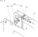
- FIG. 5 is an exploded perspective view of a coupling mechanism for coupling an electronic device, according to one embodiment of the present disclosure.
- FIG. 6 is an enlarged perspective view of major components of FIG. 5 .
- FIG. 7 is a partial perspective view of a state in which a coupling mechanism for coupling an electronic device in FIG. 5 is mounted.
- the coupling mechanism 500 is inserted between the front cover 100 and the rear cover 300.
- the coupling mechanism 500 is held in the accommodation hole 12 of the outer casing 10 while the front cover 100 and the rear cover 300 are coupled to each other.
- the coupling mechanism 500 allows the electronic device 30 to remain in a coupled state to the outer casing 10.
- the coupling mechanism 500 includes a hook-shaped bracket 510 held to hook the outer casing 10, a main bracket-mounted portion 530 defined in the front cover 100, and an auxiliary bracket-mounted portion 550 defined in the rear cover 300.
- the hook-shaped bracket 510 is held to hook the outer casing 10.
- the bracket-mounted portions into which the hook-shaped bracket 510 are mounted are also a key component of the present mechanism.
- the main bracket-mounted portion 530 and the auxiliary bracket-mounted portion 550 together with the hook-shaped bracket 510 constitutes the coupling mechanism 500.
- the hook-shaped bracket 510 is made of a rigid metal material.
- the hook-shaped bracket 510 is produced by bending a plate-shaped metal material a plurality of times.
- the hook-shaped bracket 510 has a predetermined elasticity.
- the hook-shaped bracket 510 may include a hooking portion 512 held to hook the outer casing 10, a bracket body 514 extending to one end of the hooking portion 512, first stoppers 514a extending from both side of the bracket body 514, and second stoppers 516 that extends and bends from one end of the bracket body 514.
- a distal end portion of the second stopper 516 is bent to form a third stopper 516a.
- the hooking portion 512 is formed by bending a metal material having a predetermined width into a hook shape. A distal end of the hooking portion 512 is spaced apart from the bracket body 514 by a predetermined distance. Accordingly, when the hooking portion 512 passes through the accommodation hole 12 of the outer casing 10, the hooking portion 512 is deformed against a portion defining the accommodation hole 12 and is then inserted into the accommodation hole 12. After the hooking portion 512 has passed through the accommodation hole 12 of the outer casing 10, the hooking portion 512 is restored via an elasticity and caught on the rear face of the outer casing 10. This will be described later. For this purpose, the hooking portion 512 is oriented so that a small height side of the inclined portion is directed in the insertion direction of the hook-shaped bracket 510 into the outer casing.
- the bracket body 514 has the same width as the hooking portion 512.
- the bracket body 514 extends in a direction away from the small height side of the hooking portion 512.
- Both first stoppers 514a extend vertically from both longitudinal-directional sides of the bracket body 514 respectively.
- the first stoppers 514s may stop a vertical movement of the main bracket-mounted portion 530 to be described later.
- Each first stopper 514a is bent at a right angle toward the second stopper 516 by a width corresponding to a thickness of the main bracket-mounted portion 530 and then extends in a direction parallel to the bracket body 514. That is, the first stopper 514a is bent from the bracket body 514 at a right angle in an opposite direction to the hooking portion 512 and then is bent at a right angle to extend in a direction parallel to the bracket body 514.
- the first stopper 514a should not affect the insertion and resilient deformation of the hooking portion 512.
- the first stopper 514a is disposed in a region other than a region where the hooking portion 512 is formed.
- the two second stoppers 516 extends from the bracket body 514, and are bent at a right angle downwardly and then bent at a right angle such that the two second stoppers 516 are parallel to the bracket body 514.
- the second stopper 516 should not affect the insertion and resilient deformation of the hooking portion 512. Accordingly, a pair of the second stoppers 516 may be formed into a U-shape by cutting and removing a middle portion of the plate by a width of the hooking portion 512. A distal end of each of the second stoppers 516 may be bent in the direction opposite to the hooking portion 512 to form each third stopper 516a.
- the front cover 100 has the main bracket-mounted portion 530 defined therein corresponding to the shape of the hooking portion 512 of the hook-shaped bracket 510 and the shape of the first stopper 514a.
- the auxiliary bracket-mounted portion 550 corresponding to the shape of the third stopper 516a may be defined in the rear cover 300.
- the front cover 100 is cut at plural locations in the second frame 130 to form plural grooves so that plural hook-shaped brackets 510 are inserted in the grooves respectively.
- the cut portion may define the main bracket-mounted portion 530.
- Each main bracket-mounted portion 530 defines a substantially "90 degree-rotated U" shaped receiving space.
- the hook-shaped bracket 510 is inserted into the receiving space.
- the main bracket-mounted portion 530 includes an bracket-mounted groove 532 cut into the outer casing 10 and a first rib 534 and a second rib 536 defined integrally with the second frame 130 and defining a receiving space.
- the main bracket-mounted portion 530 includes a bracket-mounted groove 532 opening toward the outer casing 10, first ribs 534 and second ribs 536, both ribs being integral with the second frame 130.
- Each first rib 534 is spaced form each second rib 536.
- the bracket-mounted groove 532 may receive the hooking portion 512 which is exposed outwardly.
- the bracket-mounted groove 532 is cut away by a width corresponding to the width of the hooking portion 512.
- the first rib 534 is projected from the inner face of the second frame 130.
- the first ribs 534 may correspond to the two first stopper 514a respectively.
- the bracket body 514 may be disposed between the two first ribs 534.
- the above-mentioned first stopper 514a is vertically bent from the bracket body 514 by a vertical dimension of the first rib 534.
- Each first stopper 514a closely contacts each first rib 534.
- a horizontal portion of the first stopper 514a is in close contact with a bottom face of the first rib 534 as shown in FIG. 7 .
- the first stopper 514a prevents the vertical movement of the hook-shaped bracket 510 on FIG. 7 .
- Each first rib may be formed in an elongate bar.
- the second rib 536 is projected from the inner face of the second frame 130.
- the second ribs 536 may correspond to the two second stopper 516 respectively. Both each first rib and each second rib are disposed between each second rib and each first rib. Each second rib may be formed in an elongate bar.
- Each second stopper 516 closely contacts each second rib 536. A horizontal portion of the second stopper 516 is in close contact with a top face of the second rib 536 as shown in FIG. 7 .
- the second stopper 516 prevents the vertical movement of the hook-shaped bracket 510 on FIG. 7 .
- Each third stopper 516a is inserted between each second rib 536 and a portion defining the auxiliary bracket-mounted portion 550.
- the first rib 534 and the second rib 536 are formed in a bar shape, and the accommodation space in which the first and second stoppers of the hook-shaped bracket 510 are inserted is defined between the first rib 534 and the second rib 536.
- the present disclosure is not limited thereto.
- the main bracket-mounted portion may be constructed into a partially opened box shape such that a portion into which the hook-shaped bracket 510 is inserted and a portion through which the hooking portion 512 is exposed are opened and a remaining portion is blocked.
- the auxiliary bracket-mounted portion 550 is formed on the rear cover 300 from an inner face portion thereof coupled with the front cover 100.
- the auxiliary bracket-mounted portion 550 is defined at a position corresponding to the position of the hook-shaped bracket 510.
- the auxiliary bracket-mounted portion 550 protrudes from the inner face of the rear cover 300 toward the front cover 100.
- the auxiliary bracket-mounted portion 550 is in close contact with the third stopper 516a formed from the distal end of the second stopper 516 of the hook-shaped bracket 510 to press the third stopper 516a. Accordingly, the auxiliary bracket-mounted portion 550 prevents the hook-shaped bracket 510 from moving in the forward and backward directions on FIG. 5 .
- the auxiliary bracket-mounted portion 550 protrudes from the rear cover 300 such that one side of the auxiliary bracket-mounted portion 550 is in close contact with the third stopper 516a when the coupling between the front cover 100 and the rear cover 300 occurs.
- the auxiliary bracket-mounted portion 550 may have a shape such as a U-shape corresponding to the shape of the third stoppers 516a so as to sufficiently cover the third stoppers 516a and thus to closely contact the third stoppers 516a.
- the auxiliary bracket-mounted portion 550 may have a plate shape having a width equal to or greater than an outer width of the pair of third stoppers.
- the hook-shaped bracket 510 is prevented from moving upward and downward with reference to FIG. 5 by the main bracket-mounted portion 530.
- the hook-shaped bracket 510 is prevented from moving back and forth by the auxiliary bracket-mounted portion 550.
- the front cover 100 and the rear cover 300 are mutually coupled to each other. Therefore, a state in which the hook-shaped bracket 510 is stably mounted on the front cover 100 may be maintained.
- the hook-shaped bracket 510 may not be released from the electronic device 30.
- the electronic device 30 may be stably mounted on the outer casing 10.
- the coupling mechanism for coupling the electronic device As described above, manufacturing the coupling mechanism for coupling the electronic device with the rigid material, the durability of the mechanism is improved, and the product cost is reduced. Further, this may prevent breakage of the coupling mechanism when coupling the device to the outer casing. Further, since the coupling mechanism may be simply inserted and installed, the installation convenience and workability are improved.
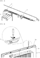
- FIG. 8 is a side view showing a state before the electronic device is mounted on the outer casing using the coupling mechanism for coupling the electronic device according to an embodiment of the present disclosure.
- FIG. 9 is a side view showing a state where the electronic device has been mounted on the outer casing using the coupling mechanism for coupling the electronic device according to an embodiment of the present disclosure.
- the hook-shaped bracket 510 is coupled to the front cover 100
- the rear cover 300 is coupled to the front cover 100 for subsequent installation of the electronic device 30.
- the electronic device 30 is roughly coupled to the outer casing 10 via the process as described referring to FIG. 5 to FIG. 7 .
- the electronic device 30 is inserted into the accommodation hole 12 in the outer casing 10. At this time, the electronic device 30 is inserted into the outer casing 10 in a direction from a front of the casing 10 to a rear thereof.
- the hooking portion 512 of the hook-shaped bracket 510 is upwardly inclined in a direction toward the front cover 100. Therefore, the hooking portion 512 has a small height portion which is first inserted into the accommodation hole 12. The inclined portion is pressed while the rear cover 300 of the electronic device 30 passes through the accommodation hole 12.
- the hooking portion 512 is pressed and is elastically deformed and thus a distal end of the hooking portion 512 approaches the bracket body 514 and passes through the accommodation hole 12.
- the hooking portion 512 is restored after passing through the accommodation hole 12.
- the hooking portion 512 is located out of the accommodation hole 12 on FIG. 9 , so that the hooking portion 512 is held to hook the outer casing 10.
- the electronic device 30 is in a state in which the front cover 100 and the rear cover 300 thereof face each other with the outer casing 10 being disposed therebetween.
- the hook-shaped bracket 510 may thus allow an engagement between the electronic device 30 and the outer casing 10 to be maintained.
- the electronic device 30 is not detached from the outer casing 10 while the electronic device 30 is fully secured to the outer casing 10 using additional coupling means.
- the coupling state in which the electronic device 30 is roughly pre-coupled to the outer casing 10 before the electronic device 30 is completely fixed to the outer casing using additional coupling means may be referred to as “pre-coupling state” or “roughly coupling state”. While the electronic device 30 is roughly pre-coupled to the outer casing 10, the electronic device 30 is fully secured to the outer casing 10 using additional coupling means.
- the coupling state in which the electronic device 30 is fixedly coupled to the outer casing 10 may be referred to as "post-coupling state” or "completely coupling state”. In this process, the electronic device 30 can be installed to the outer casing only by a single operator.
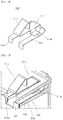
- FIG. 10 is a perspective view showing a coupling mechanism for coupling an electronic device according to another embodiment of the present disclosure.
- FIG. 11 is a perspective view showing a coupling mechanism for coupling an electronic device according to still another embodiment of the present disclosure.
- a coupling mechanism 500' for coupling an electronic device is the same as the hook-shaped bracket 510 as described in the embodiment of FIG. 6 except that a second stopper 516' is free of a cut portion and is formed of a complete plate.
- the hooking portion 512' may be elastically deformed because the hooking portion 512' and the second stopper 516' are spaced by a predetermined distance. Further, an area of the coupling mechanism as pressed by the auxiliary bracket-mounted portion (Refer to FIG. 5 ) increases. Thus, the installation stability of the hook-shaped bracket 510' is further improved.
- the second stoppers may be formed in the same manner as the second stoppers as described in FIG. 5 such that lengths of the second stoppers increase.
- the rear cover may have holes into which the second stoppers are inserted. In this case, since the second stoppers are inserted and fixed in the rear cover, this has the effect of restricting the forward-backward movement of the hook-shaped bracket like the embodiment of FIG. 5 in which the third stoppers are formed.
- a hook-shaped bracket 510" according to another embodiment of the present disclosure has the same structure as the embodiment described in FIG. 5 , except that each of first stoppers 514a" has a 90-degree rotated U shaped cross section.
- first stoppers 514a" since the first stopper 514a" wraps the first rib (See FIG. 7 ) of the main bracket-mounted portion 530", the upward and downward movement of the hook-shaped bracket 510" may be restricted as in the embodiment of FIG. 5 . Therefore, the installation stability of the coupling mechanism is further improved.
- auxiliary bracket-mounted portion is described as being provided on the rear cover in the above embodiments, the present disclosure is not limited thereto.
- the auxiliary bracket-mounted portion may be formed as a separate component and may be coupled with the hook-shaped bracket.
- the auxiliary bracket-mounted portion is not limited to a specific shape as long as it can prevent the forward-backward movement of the hook-shaped bracket by securing the second stopper or the third stopper of the hook-shaped bracket.
Landscapes
- Engineering & Computer Science (AREA)
- Theoretical Computer Science (AREA)
- General Engineering & Computer Science (AREA)
- Computer Hardware Design (AREA)
- Human Computer Interaction (AREA)
- Physics & Mathematics (AREA)
- General Physics & Mathematics (AREA)
- Microelectronics & Electronic Packaging (AREA)
- Power Engineering (AREA)
- Computer Security & Cryptography (AREA)
- Casings For Electric Apparatus (AREA)
Claims (9)
- Elektronisches Gerät (30), umfassend:eine vordere Abdeckung (100), die aus einem äußeren Gehäuse (10) herausragt;eine hintere Abdeckung (300), die an eine Rückseite der vorderen Abdeckung (100) gekoppelt ist; undeinen Kopplungsmechanismus (500, 500' oder 500") zum Koppeln des elektronischen Geräts (30) an das äußere Gehäuse (10),wobei das äußere Gehäuse eine darin definierte Aufnahmebohrung (12) aufweist, die so bemessen ist, dass sie einer Größe des elektronischen Geräts (30) entspricht,wobei der Kopplungsmechanismus (500) umfasst:eine Vielzahl von hakenförmigen Halterungen (510), die zwischen der vorderen und hinteren Abdeckung (100 und 300) angeordnet sind, wobei die Vielzahl von hakenförmigen Halterungen (510) so konfiguriert sind, dass sie durch die Aufnahmebohrung (12) hindurchgehen und dort gehalten werden, um das äußere Gehäuse einzuhaken, während die vordere Abdeckung (100) und die hintere Abdeckung (300) miteinander gekoppelt sind;eine Vielzahl von an Haupthalterungen befestigten Abschnitten (530), die in der vorderen Abdeckung (100) definiert sind, wobei jede der hakenförmigen Halterungen (510) in jedem der Vielzahl von an Haupthalterungen befestigten Abschnitten (530) befestigt ist; undeine Vielzahl von an Hilfshalterungen befestigten Abschnitten (550), die an der hinteren Abdeckung (300) angeordnet sind, wobei jeder der Vielzahl von an Hilfshalterungen befestigten Abschnitten (550) so konfiguriert ist, dass er mit jedem der Vielzahl von hakenförmigen Halterungen (510) in Eingriff gebracht werden kann, wenn die vordere Abdeckung (100) und die hintere Abdeckung (300) miteinander gekoppelt sind,wobei das elektronische Gerät (30) dadurch gekennzeichnet ist:dass jede der Vielzahl von hakenförmigen Halterungen (510) umfasst:einen hakenförmigen Abschnitt (512), der in einer Richtung auf die vordere Abdeckung (100) geneigt ist und gehalten wird, um das äußere Gehäuse (10) einzuhaken; undeinen Halterungskörper (514) mit einer Breite, die gleich der Breite des Hakenabschnitts (512) ist und sich horizontal von einem Ende des Hakenabschnitts (512) erstreckt, unddass jeder der Vielzahl von an Haupthalterungen befestigten Abschnitten (530), umfasst:eine an einer Halterung befestigte Nut (532), die in einem zweiten Rahmen (130) definiert ist, wobei der zweite Rahmen (130) mit einem ersten Rahmen (110) entlang einer Kante desselben gekoppelt ist, wobei der erste Rahmen mit einer Vorderseite der vorderen Abdeckung (100) gekoppelt ist, wobei die Nut (532) der Halterung zum äußere Gehäuse hin offen ist; underste Rippen (534) und zweite Rippen (536), die einstückig mit dem zweiten Rahmen(130) ausgebildet sind, wobei ein Aufnahmeraum zum Empfangen der Vielzahl von hakenförmigen Halterungen(510) zwischen den ersten Rippen (534) und den zweiten Rippen (536) definiert ist.
- Elektronisches Gerät (30) nach Anspruch 1, wobei jede der Vielzahl von hakenförmigen Halterungen (510) ferner umfasst:erste Stopper (514a), die einstückig mit dem Halterungskörper (514) an beiden gegenüberliegenden Seiten des Halterungskörpers ausgebildet sind; undeinen zweiten Stopper (516), der sich vertikal erstreckt und sich dann horizontal von einem Ende desHalterungskörpers (514) erstreckt, und zwar so, dass der zweite Stopper (516) vom Halterungskörper (514) weg weist.
- Elektronisches Gerät (30) nach Anspruch 2, wobei die Vielzahl der hakenförmigen Halterungen (510) aus starrem Metall hergestellt sind,
wobei der Hakenabschnitt (512) und der Halterungskörper (514) so konfiguriert sind, dass sie durch Drücken und elastische Verformung in die Aufnahmebohrung (12) eingeführt und elastisch zurückgestellt werden können, sodass der Hakenabschnitt (512) gehalten wird, um das äußere Gehäuse (10) einzuhaken. - Elektronisches Gerät (30) nach Anspruch 2 und 3, wobei die an der Halterung befestigte Nut (532) eine Breite hat, die der Breite des hakenförmigen Abschnitts (512) entspricht,
wobei jede der ersten Rippen (534) einen länglichen Stab beinhaltet, wobei der längliche Stab jeder der ersten Rippen von einer Innenfläche des zweiten Rahmens (130) vorsteht, wobei der Halterungskörper (514) zwischen den Stäben der ersten Rippen (534) angeordnet ist,
wobei jede der zweiten Rippen (536) einen länglichen Stab beinhaltet, wobei der längliche Stab jeder der zweiten Rippen von der Innenfläche des zweiten Rahmens (130) vorsteht, wobei die ersten Stopper (514a) und der zweite Stopper (516) zwischen jeder der ersten Rippen und jeder der zweiten Rippen angeordnet sind, wobei jede der zweiten Rippen unterhalb jeder der ersten Rippen angeordnet ist. - Elektronisches Gerät (30) nach Anspruch 4, wobei sich jeder der ersten Stopper (514a) vertikal nach unten erstreckt und dann horizontal nach außen von dem Halterungskörper (514) erstreckt, wobei jeder der ersten Stopper (514a) eine horizontale Abmessung aufweist, die gleich einer horizontalen Abmessung jeder der ersten Rippen (534) ist, wobei jeder der ersten Stopper (514a) in engem Kontakt mit jeder der ersten Rippen (534) steht,
wobei der zweite Stopper (516) in engem Kontakt mit den zweiten Rippen (536) steht. - Elektronisches Gerät (30) nach Anspruch 5, wobei jede der Vielzahl von hakenförmigen Halterungen (510) einen dritten Stopper (516) beinhaltet, der sich von einem distalen Ende des zweiten Stoppers (516) vertikal nach unten erstreckt,
wobei jeder der Vielzahl von an Hilfshalterungen befestigten Abschnitten (550) in einer Plattenform von einer Innenfläche der hinteren Abdeckung (300) und an einer Position, die einer Position jedes der Vielzahl von an Haupthalterungen befestigten Abschnitten (530) entspricht, vorsteht,
wobei jeder der Vielzahl von an Hilfshalterungen befestigten Abschnitten (550) den dritten Anschlag 516a kontaktiert und gegen ihn drückt, wenn die vordere Abdeckung (100) und die hintere Abdeckung (300) miteinander gekoppelt sind. - Elektronisches Gerät (30) nach Anspruch 6, wobei der zweite Stopper einen horizontalen Abschnitt aufweist, der sich in eine U-Form verzweigt, wobei der dritte Stopper (516a) eine Vielzahl von dritten Stoppern umfasst und jeder der Vielzahl von dritten Stoppern an einem distalen Ende jedes der Zinken der U-Form ausgebildet ist.
- Elektronisches Gerät (30) nach Anspruch 6, wobei der zweite Stopper (516') einen horizontalen Abschnitt mit einer Breite aufweist, die größer als die Breite des Halterungskörpers (514') ist, wobei der dritte Stopper (516a') an einem distalen Ende des zweiten Stoppers (516') ausgebildet ist.
- Elektronisches Gerät (30) nach Anspruch 5, wobei jeder der ersten Stopper (514") einen um 90 Grad gedrehten U-förmigen Querschnitt aufweist, sodass jeder der ersten Stopper (514a") jede der ersten Rippen (534") umhüllt.
Applications Claiming Priority (1)
| Application Number | Priority Date | Filing Date | Title |
|---|---|---|---|
| KR1020180020405A KR101976432B1 (ko) | 2018-02-21 | 2018-02-21 | 전자기기의 결합 장치 |
Publications (2)
| Publication Number | Publication Date |
|---|---|
| EP3531233A1 EP3531233A1 (de) | 2019-08-28 |
| EP3531233B1 true EP3531233B1 (de) | 2020-10-28 |
Family
ID=65598416
Family Applications (1)
| Application Number | Title | Priority Date | Filing Date |
|---|---|---|---|
| EP19158107.3A Active EP3531233B1 (de) | 2018-02-21 | 2019-02-19 | Kopplungsmechanismus zur kopplung einer elektronischen vorrichtung |
Country Status (6)
| Country | Link |
|---|---|
| US (1) | US10667415B2 (de) |
| EP (1) | EP3531233B1 (de) |
| JP (1) | JP6724181B2 (de) |
| KR (1) | KR101976432B1 (de) |
| CN (1) | CN110174926B (de) |
| ES (1) | ES2836704T3 (de) |
Families Citing this family (6)
| Publication number | Priority date | Publication date | Assignee | Title |
|---|---|---|---|---|
| KR102431932B1 (ko) * | 2020-06-11 | 2022-08-11 | 이덕환 | 패널 유니트가 구비된 mcc |
| JP7581898B2 (ja) * | 2021-01-18 | 2024-11-13 | オムロン株式会社 | 電気機器 |
| KR102426354B1 (ko) | 2021-07-19 | 2022-07-29 | 엘지전자 주식회사 | 마스크 장치 |
| KR102661736B1 (ko) * | 2022-08-19 | 2024-04-26 | 엘에스일렉트릭(주) | 결합 부재 및 이를 포함하는 전력 전자기기 |
| KR102661767B1 (ko) * | 2022-12-02 | 2024-04-30 | 주식회사 오성전자 | 2중 잠금구조를 갖는 전자제품용 리모컨 |
| KR102924931B1 (ko) * | 2023-12-28 | 2026-02-09 | 주식회사 오성전자 | 2단 오픈 구조의 배터리 커버를 구비한 리모컨 |
Family Cites Families (16)
| Publication number | Priority date | Publication date | Assignee | Title |
|---|---|---|---|---|
| DE3605143A1 (de) | 1986-02-18 | 1987-08-20 | Siemens Ag | Haltebuegel zur befestigung eines flachen bauteiles an einem gehaeuseteil |
| JP2646185B2 (ja) * | 1993-09-10 | 1997-08-25 | スタンレー電気株式会社 | 箱 体 |
| JPH11268595A (ja) * | 1998-03-25 | 1999-10-05 | Sony Corp | 乗物搭載用音響装置 |
| JP4254999B2 (ja) * | 2002-12-26 | 2009-04-15 | パナソニック株式会社 | 筐体の壁掛け構造 |
| CN2613803Y (zh) * | 2003-02-17 | 2004-04-28 | 鸿富锦精密工业(深圳)有限公司 | 扩充卡固定结构 |
| US6826863B1 (en) * | 2003-09-09 | 2004-12-07 | Pacific Digital Corporation | Combination video monitor and detachable picture frame |
| KR20080019472A (ko) * | 2006-08-28 | 2008-03-04 | 주식회사 대우일렉트로닉스 | 평판 텔레비전의 벽걸이 장치 |
| CN201039613Y (zh) * | 2007-04-28 | 2008-03-19 | 佛山市顺德区顺达电脑厂有限公司 | 电子设备之面板与机壳的固定连接结构 |
| CN102194589A (zh) * | 2010-03-03 | 2011-09-21 | 英业达股份有限公司 | 两件式电源钮卡合结构 |
| AU2013203842A1 (en) * | 2010-03-29 | 2013-05-02 | Eat Dirt, Llc | Cases and covers for electronic handheld devices |
| JP5502642B2 (ja) * | 2010-07-22 | 2014-05-28 | 株式会社デジタル | 電子機器の仮止め構造 |
| JP5649638B2 (ja) * | 2012-12-10 | 2015-01-07 | 三菱電機株式会社 | 制御装置 |
| CN104076885B (zh) * | 2013-03-27 | 2017-08-08 | 光宝电子(广州)有限公司 | 介面卡的支撑固持结构 |
| JP6102411B2 (ja) * | 2013-03-28 | 2017-03-29 | オムロン株式会社 | 電気機器および電気機器用取付具 |
| DE102016102138A1 (de) * | 2016-02-08 | 2017-08-10 | Phoenix Contact Gmbh & Co. Kg | Montagerahmen zum Befestigen einer Funktionseinheit an einer Gerätewandung |
| KR102325744B1 (ko) * | 2017-03-06 | 2021-11-11 | 엘에스일렉트릭(주) | 전자기기 고정용 브라켓 및 전자기기 고정 구조 |
-
2018
- 2018-02-21 KR KR1020180020405A patent/KR101976432B1/ko active Active
-
2019
- 2019-02-01 JP JP2019017096A patent/JP6724181B2/ja active Active
- 2019-02-15 CN CN201910117009.3A patent/CN110174926B/zh active Active
- 2019-02-15 US US16/277,359 patent/US10667415B2/en active Active
- 2019-02-19 EP EP19158107.3A patent/EP3531233B1/de active Active
- 2019-02-19 ES ES19158107T patent/ES2836704T3/es active Active
Non-Patent Citations (1)
| Title |
|---|
| None * |
Also Published As
| Publication number | Publication date |
|---|---|
| US20190261522A1 (en) | 2019-08-22 |
| EP3531233A1 (de) | 2019-08-28 |
| JP2019145788A (ja) | 2019-08-29 |
| CN110174926B (zh) | 2023-09-19 |
| ES2836704T3 (es) | 2021-06-28 |
| CN110174926A (zh) | 2019-08-27 |
| US10667415B2 (en) | 2020-05-26 |
| JP6724181B2 (ja) | 2020-07-15 |
| KR101976432B1 (ko) | 2019-05-09 |
Similar Documents
| Publication | Publication Date | Title |
|---|---|---|
| US10667415B2 (en) | Coupling mechanism for coupling electronic device | |
| US7486506B2 (en) | Mounting assembly for enclosure cover | |
| US8897018B2 (en) | Display device and television receiver | |
| US8672425B2 (en) | Cabinet structure assembly | |
| US20070222347A1 (en) | Mounting assembly for side panel of computer enclosure | |
| CN107772856A (zh) | 将前挡板可拆卸固定于抽屉的装置及抽屉前挡板拆装方法 | |
| US20050117289A1 (en) | Mounting apparatus for storage devices | |
| EP2497993B1 (de) | Gehäusestrukturbaugruppe | |
| US20060166549A1 (en) | Wire cover for connectors | |
| JP6183653B2 (ja) | インストルメントパネルの加飾部品の取り付け構造 | |
| WO2013061798A1 (ja) | 内蔵デバイスの着脱作業性に優れたpos端末装置 | |
| KR20200018157A (ko) | 차량용 헤드업 디스플레이 장치 | |
| CA3044148C (en) | Quick release chassis cover | |
| EP2059036A1 (de) | Anzeige | |
| JP6092598B2 (ja) | ブラインド取付用ブラケット | |
| JP3740997B2 (ja) | 配線器具用プレート | |
| KR102425648B1 (ko) | 차량용 헤드업 디스플레이 장치 | |
| KR101628915B1 (ko) | 차량용 계기판의 엘씨디 모듈 조립장치 | |
| JP7762553B2 (ja) | 表示装置 | |
| JP2006069276A (ja) | リヤカメラの取付け構造 | |
| JP3825602B2 (ja) | ケースの取付け構造及び取付け方法 | |
| JP2010148339A (ja) | 配線装置用プレートおよび配線装置 | |
| WO2026034104A1 (ja) | 衣類処理装置 | |
| WO2023204149A1 (ja) | 電気接続箱 | |
| JP2008037176A (ja) | 車両アンテナの着脱構造 |
Legal Events
| Date | Code | Title | Description |
|---|---|---|---|
| PUAI | Public reference made under article 153(3) epc to a published international application that has entered the european phase |
Free format text: ORIGINAL CODE: 0009012 |
|
| STAA | Information on the status of an ep patent application or granted ep patent |
Free format text: STATUS: THE APPLICATION HAS BEEN PUBLISHED |
|
| AK | Designated contracting states |
Kind code of ref document: A1 Designated state(s): AL AT BE BG CH CY CZ DE DK EE ES FI FR GB GR HR HU IE IS IT LI LT LU LV MC MK MT NL NO PL PT RO RS SE SI SK SM TR |
|
| AX | Request for extension of the european patent |
Extension state: BA ME |
|
| STAA | Information on the status of an ep patent application or granted ep patent |
Free format text: STATUS: REQUEST FOR EXAMINATION WAS MADE |
|
| 17P | Request for examination filed |
Effective date: 20200226 |
|
| RBV | Designated contracting states (corrected) |
Designated state(s): AL AT BE BG CH CY CZ DE DK EE ES FI FR GB GR HR HU IE IS IT LI LT LU LV MC MK MT NL NO PL PT RO RS SE SI SK SM TR |
|
| GRAP | Despatch of communication of intention to grant a patent |
Free format text: ORIGINAL CODE: EPIDOSNIGR1 |
|
| STAA | Information on the status of an ep patent application or granted ep patent |
Free format text: STATUS: GRANT OF PATENT IS INTENDED |
|
| INTG | Intention to grant announced |
Effective date: 20200626 |
|
| GRAS | Grant fee paid |
Free format text: ORIGINAL CODE: EPIDOSNIGR3 |
|
| GRAA | (expected) grant |
Free format text: ORIGINAL CODE: 0009210 |
|
| STAA | Information on the status of an ep patent application or granted ep patent |
Free format text: STATUS: THE PATENT HAS BEEN GRANTED |
|
| AK | Designated contracting states |
Kind code of ref document: B1 Designated state(s): AL AT BE BG CH CY CZ DE DK EE ES FI FR GB GR HR HU IE IS IT LI LT LU LV MC MK MT NL NO PL PT RO RS SE SI SK SM TR |
|
| REG | Reference to a national code |
Ref country code: GB Ref legal event code: FG4D |
|
| REG | Reference to a national code |
Ref country code: CH Ref legal event code: EP |
|
| REG | Reference to a national code |
Ref country code: AT Ref legal event code: REF Ref document number: 1328861 Country of ref document: AT Kind code of ref document: T Effective date: 20201115 |
|
| REG | Reference to a national code |
Ref country code: DE Ref legal event code: R096 Ref document number: 602019001060 Country of ref document: DE |
|
| REG | Reference to a national code |
Ref country code: IE Ref legal event code: FG4D |
|
| REG | Reference to a national code |
Ref country code: AT Ref legal event code: MK05 Ref document number: 1328861 Country of ref document: AT Kind code of ref document: T Effective date: 20201028 |
|
| REG | Reference to a national code |
Ref country code: NL Ref legal event code: MP Effective date: 20201028 |
|
| PG25 | Lapsed in a contracting state [announced via postgrant information from national office to epo] |
Ref country code: GR Free format text: LAPSE BECAUSE OF FAILURE TO SUBMIT A TRANSLATION OF THE DESCRIPTION OR TO PAY THE FEE WITHIN THE PRESCRIBED TIME-LIMIT Effective date: 20210129 Ref country code: NO Free format text: LAPSE BECAUSE OF FAILURE TO SUBMIT A TRANSLATION OF THE DESCRIPTION OR TO PAY THE FEE WITHIN THE PRESCRIBED TIME-LIMIT Effective date: 20210128 Ref country code: FI Free format text: LAPSE BECAUSE OF FAILURE TO SUBMIT A TRANSLATION OF THE DESCRIPTION OR TO PAY THE FEE WITHIN THE PRESCRIBED TIME-LIMIT Effective date: 20201028 Ref country code: PT Free format text: LAPSE BECAUSE OF FAILURE TO SUBMIT A TRANSLATION OF THE DESCRIPTION OR TO PAY THE FEE WITHIN THE PRESCRIBED TIME-LIMIT Effective date: 20210301 Ref country code: RS Free format text: LAPSE BECAUSE OF FAILURE TO SUBMIT A TRANSLATION OF THE DESCRIPTION OR TO PAY THE FEE WITHIN THE PRESCRIBED TIME-LIMIT Effective date: 20201028 |
|
| REG | Reference to a national code |
Ref country code: LT Ref legal event code: MG4D |
|
| PG25 | Lapsed in a contracting state [announced via postgrant information from national office to epo] |
Ref country code: BG Free format text: LAPSE BECAUSE OF FAILURE TO SUBMIT A TRANSLATION OF THE DESCRIPTION OR TO PAY THE FEE WITHIN THE PRESCRIBED TIME-LIMIT Effective date: 20210128 Ref country code: IS Free format text: LAPSE BECAUSE OF FAILURE TO SUBMIT A TRANSLATION OF THE DESCRIPTION OR TO PAY THE FEE WITHIN THE PRESCRIBED TIME-LIMIT Effective date: 20210228 Ref country code: PL Free format text: LAPSE BECAUSE OF FAILURE TO SUBMIT A TRANSLATION OF THE DESCRIPTION OR TO PAY THE FEE WITHIN THE PRESCRIBED TIME-LIMIT Effective date: 20201028 Ref country code: LV Free format text: LAPSE BECAUSE OF FAILURE TO SUBMIT A TRANSLATION OF THE DESCRIPTION OR TO PAY THE FEE WITHIN THE PRESCRIBED TIME-LIMIT Effective date: 20201028 Ref country code: SE Free format text: LAPSE BECAUSE OF FAILURE TO SUBMIT A TRANSLATION OF THE DESCRIPTION OR TO PAY THE FEE WITHIN THE PRESCRIBED TIME-LIMIT Effective date: 20201028 Ref country code: AT Free format text: LAPSE BECAUSE OF FAILURE TO SUBMIT A TRANSLATION OF THE DESCRIPTION OR TO PAY THE FEE WITHIN THE PRESCRIBED TIME-LIMIT Effective date: 20201028 |
|
| REG | Reference to a national code |
Ref country code: ES Ref legal event code: FG2A Ref document number: 2836704 Country of ref document: ES Kind code of ref document: T3 Effective date: 20210628 |
|
| PG25 | Lapsed in a contracting state [announced via postgrant information from national office to epo] |
Ref country code: HR Free format text: LAPSE BECAUSE OF FAILURE TO SUBMIT A TRANSLATION OF THE DESCRIPTION OR TO PAY THE FEE WITHIN THE PRESCRIBED TIME-LIMIT Effective date: 20201028 Ref country code: NL Free format text: LAPSE BECAUSE OF FAILURE TO SUBMIT A TRANSLATION OF THE DESCRIPTION OR TO PAY THE FEE WITHIN THE PRESCRIBED TIME-LIMIT Effective date: 20201028 |
|
| REG | Reference to a national code |
Ref country code: DE Ref legal event code: R097 Ref document number: 602019001060 Country of ref document: DE |
|
| PG25 | Lapsed in a contracting state [announced via postgrant information from national office to epo] |
Ref country code: CZ Free format text: LAPSE BECAUSE OF FAILURE TO SUBMIT A TRANSLATION OF THE DESCRIPTION OR TO PAY THE FEE WITHIN THE PRESCRIBED TIME-LIMIT Effective date: 20201028 Ref country code: EE Free format text: LAPSE BECAUSE OF FAILURE TO SUBMIT A TRANSLATION OF THE DESCRIPTION OR TO PAY THE FEE WITHIN THE PRESCRIBED TIME-LIMIT Effective date: 20201028 Ref country code: SK Free format text: LAPSE BECAUSE OF FAILURE TO SUBMIT A TRANSLATION OF THE DESCRIPTION OR TO PAY THE FEE WITHIN THE PRESCRIBED TIME-LIMIT Effective date: 20201028 Ref country code: SM Free format text: LAPSE BECAUSE OF FAILURE TO SUBMIT A TRANSLATION OF THE DESCRIPTION OR TO PAY THE FEE WITHIN THE PRESCRIBED TIME-LIMIT Effective date: 20201028 Ref country code: RO Free format text: LAPSE BECAUSE OF FAILURE TO SUBMIT A TRANSLATION OF THE DESCRIPTION OR TO PAY THE FEE WITHIN THE PRESCRIBED TIME-LIMIT Effective date: 20201028 Ref country code: LT Free format text: LAPSE BECAUSE OF FAILURE TO SUBMIT A TRANSLATION OF THE DESCRIPTION OR TO PAY THE FEE WITHIN THE PRESCRIBED TIME-LIMIT Effective date: 20201028 |
|
| PG25 | Lapsed in a contracting state [announced via postgrant information from national office to epo] |
Ref country code: DK Free format text: LAPSE BECAUSE OF FAILURE TO SUBMIT A TRANSLATION OF THE DESCRIPTION OR TO PAY THE FEE WITHIN THE PRESCRIBED TIME-LIMIT Effective date: 20201028 |
|
| PLBE | No opposition filed within time limit |
Free format text: ORIGINAL CODE: 0009261 |
|
| STAA | Information on the status of an ep patent application or granted ep patent |
Free format text: STATUS: NO OPPOSITION FILED WITHIN TIME LIMIT |
|
| PG25 | Lapsed in a contracting state [announced via postgrant information from national office to epo] |
Ref country code: MC Free format text: LAPSE BECAUSE OF FAILURE TO SUBMIT A TRANSLATION OF THE DESCRIPTION OR TO PAY THE FEE WITHIN THE PRESCRIBED TIME-LIMIT Effective date: 20201028 |
|
| 26N | No opposition filed |
Effective date: 20210729 |
|
| REG | Reference to a national code |
Ref country code: BE Ref legal event code: MM Effective date: 20210228 |
|
| PG25 | Lapsed in a contracting state [announced via postgrant information from national office to epo] |
Ref country code: AL Free format text: LAPSE BECAUSE OF FAILURE TO SUBMIT A TRANSLATION OF THE DESCRIPTION OR TO PAY THE FEE WITHIN THE PRESCRIBED TIME-LIMIT Effective date: 20201028 Ref country code: LU Free format text: LAPSE BECAUSE OF NON-PAYMENT OF DUE FEES Effective date: 20210219 |
|
| PG25 | Lapsed in a contracting state [announced via postgrant information from national office to epo] |
Ref country code: SI Free format text: LAPSE BECAUSE OF FAILURE TO SUBMIT A TRANSLATION OF THE DESCRIPTION OR TO PAY THE FEE WITHIN THE PRESCRIBED TIME-LIMIT Effective date: 20201028 |
|
| PG25 | Lapsed in a contracting state [announced via postgrant information from national office to epo] |
Ref country code: IE Free format text: LAPSE BECAUSE OF NON-PAYMENT OF DUE FEES Effective date: 20210219 |
|
| PG25 | Lapsed in a contracting state [announced via postgrant information from national office to epo] |
Ref country code: IS Free format text: LAPSE BECAUSE OF FAILURE TO SUBMIT A TRANSLATION OF THE DESCRIPTION OR TO PAY THE FEE WITHIN THE PRESCRIBED TIME-LIMIT Effective date: 20210228 |
|
| PG25 | Lapsed in a contracting state [announced via postgrant information from national office to epo] |
Ref country code: BE Free format text: LAPSE BECAUSE OF NON-PAYMENT OF DUE FEES Effective date: 20210228 |
|
| REG | Reference to a national code |
Ref country code: CH Ref legal event code: PL |
|
| PG25 | Lapsed in a contracting state [announced via postgrant information from national office to epo] |
Ref country code: LI Free format text: LAPSE BECAUSE OF NON-PAYMENT OF DUE FEES Effective date: 20220228 Ref country code: CH Free format text: LAPSE BECAUSE OF NON-PAYMENT OF DUE FEES Effective date: 20220228 |
|
| PG25 | Lapsed in a contracting state [announced via postgrant information from national office to epo] |
Ref country code: CY Free format text: LAPSE BECAUSE OF FAILURE TO SUBMIT A TRANSLATION OF THE DESCRIPTION OR TO PAY THE FEE WITHIN THE PRESCRIBED TIME-LIMIT Effective date: 20201028 |
|
| PG25 | Lapsed in a contracting state [announced via postgrant information from national office to epo] |
Ref country code: HU Free format text: LAPSE BECAUSE OF FAILURE TO SUBMIT A TRANSLATION OF THE DESCRIPTION OR TO PAY THE FEE WITHIN THE PRESCRIBED TIME-LIMIT; INVALID AB INITIO Effective date: 20190219 |
|
| P01 | Opt-out of the competence of the unified patent court (upc) registered |
Effective date: 20230625 |
|
| PG25 | Lapsed in a contracting state [announced via postgrant information from national office to epo] |
Ref country code: MK Free format text: LAPSE BECAUSE OF FAILURE TO SUBMIT A TRANSLATION OF THE DESCRIPTION OR TO PAY THE FEE WITHIN THE PRESCRIBED TIME-LIMIT Effective date: 20201028 |
|
| PG25 | Lapsed in a contracting state [announced via postgrant information from national office to epo] |
Ref country code: MT Free format text: LAPSE BECAUSE OF FAILURE TO SUBMIT A TRANSLATION OF THE DESCRIPTION OR TO PAY THE FEE WITHIN THE PRESCRIBED TIME-LIMIT Effective date: 20201028 |
|
| PG25 | Lapsed in a contracting state [announced via postgrant information from national office to epo] |
Ref country code: TR Free format text: LAPSE BECAUSE OF FAILURE TO SUBMIT A TRANSLATION OF THE DESCRIPTION OR TO PAY THE FEE WITHIN THE PRESCRIBED TIME-LIMIT Effective date: 20201028 |
|
| PGFP | Annual fee paid to national office [announced via postgrant information from national office to epo] |
Ref country code: GB Payment date: 20251208 Year of fee payment: 8 |
|
| PGFP | Annual fee paid to national office [announced via postgrant information from national office to epo] |
Ref country code: FR Payment date: 20251209 Year of fee payment: 8 |
|
| PGFP | Annual fee paid to national office [announced via postgrant information from national office to epo] |
Ref country code: ES Payment date: 20260324 Year of fee payment: 8 |
|
| PGFP | Annual fee paid to national office [announced via postgrant information from national office to epo] |
Ref country code: DE Payment date: 20251208 Year of fee payment: 8 |
|
| PGFP | Annual fee paid to national office [announced via postgrant information from national office to epo] |
Ref country code: IT Payment date: 20251209 Year of fee payment: 8 |