EP3530640B1 - Vorrichtung zur methanherstellung und verfahren zur methanherstellung - Google Patents
Vorrichtung zur methanherstellung und verfahren zur methanherstellung Download PDFInfo
- Publication number
- EP3530640B1 EP3530640B1 EP19157367.4A EP19157367A EP3530640B1 EP 3530640 B1 EP3530640 B1 EP 3530640B1 EP 19157367 A EP19157367 A EP 19157367A EP 3530640 B1 EP3530640 B1 EP 3530640B1
- Authority
- EP
- European Patent Office
- Prior art keywords
- separator
- hydrogen
- reactor
- flow path
- supplied
- Prior art date
- Legal status (The legal status is an assumption and is not a legal conclusion. Google has not performed a legal analysis and makes no representation as to the accuracy of the status listed.)
- Active
Links
Images





Classifications
-
- C—CHEMISTRY; METALLURGY
- C10—PETROLEUM, GAS OR COKE INDUSTRIES; TECHNICAL GASES CONTAINING CARBON MONOXIDE; FUELS; LUBRICANTS; PEAT
- C10L—FUELS NOT OTHERWISE PROVIDED FOR; NATURAL GAS; SYNTHETIC NATURAL GAS OBTAINED BY PROCESSES NOT COVERED BY SUBCLASSES C10G OR C10K; LIQUIFIED PETROLEUM GAS; USE OF ADDITIVES TO FUELS OR FIRES; FIRE-LIGHTERS
- C10L3/00—Gaseous fuels; Natural gas; Synthetic natural gas obtained by processes not covered by subclass C10G, C10K; Liquefied petroleum gas
- C10L3/06—Natural gas; Synthetic natural gas obtained by processes not covered by C10G, C10K3/02 or C10K3/04
- C10L3/08—Production of synthetic natural gas
-
- B—PERFORMING OPERATIONS; TRANSPORTING
- B01—PHYSICAL OR CHEMICAL PROCESSES OR APPARATUS IN GENERAL
- B01D—SEPARATION
- B01D53/00—Separation of gases or vapours; Recovering vapours of volatile solvents from gases; Chemical or biological purification of waste gases, e.g. engine exhaust gases, smoke, fumes, flue gases, aerosols
- B01D53/02—Separation of gases or vapours; Recovering vapours of volatile solvents from gases; Chemical or biological purification of waste gases, e.g. engine exhaust gases, smoke, fumes, flue gases, aerosols by adsorption, e.g. preparative gas chromatography
- B01D53/04—Separation of gases or vapours; Recovering vapours of volatile solvents from gases; Chemical or biological purification of waste gases, e.g. engine exhaust gases, smoke, fumes, flue gases, aerosols by adsorption, e.g. preparative gas chromatography with stationary adsorbents
- B01D53/0407—Constructional details of adsorbing systems
- B01D53/0438—Cooling or heating systems
-
- B—PERFORMING OPERATIONS; TRANSPORTING
- B01—PHYSICAL OR CHEMICAL PROCESSES OR APPARATUS IN GENERAL
- B01D—SEPARATION
- B01D53/00—Separation of gases or vapours; Recovering vapours of volatile solvents from gases; Chemical or biological purification of waste gases, e.g. engine exhaust gases, smoke, fumes, flue gases, aerosols
- B01D53/02—Separation of gases or vapours; Recovering vapours of volatile solvents from gases; Chemical or biological purification of waste gases, e.g. engine exhaust gases, smoke, fumes, flue gases, aerosols by adsorption, e.g. preparative gas chromatography
- B01D53/04—Separation of gases or vapours; Recovering vapours of volatile solvents from gases; Chemical or biological purification of waste gases, e.g. engine exhaust gases, smoke, fumes, flue gases, aerosols by adsorption, e.g. preparative gas chromatography with stationary adsorbents
- B01D53/0407—Constructional details of adsorbing systems
- B01D53/0446—Means for feeding or distributing gases
-
- B—PERFORMING OPERATIONS; TRANSPORTING
- B01—PHYSICAL OR CHEMICAL PROCESSES OR APPARATUS IN GENERAL
- B01D—SEPARATION
- B01D53/00—Separation of gases or vapours; Recovering vapours of volatile solvents from gases; Chemical or biological purification of waste gases, e.g. engine exhaust gases, smoke, fumes, flue gases, aerosols
- B01D53/02—Separation of gases or vapours; Recovering vapours of volatile solvents from gases; Chemical or biological purification of waste gases, e.g. engine exhaust gases, smoke, fumes, flue gases, aerosols by adsorption, e.g. preparative gas chromatography
- B01D53/04—Separation of gases or vapours; Recovering vapours of volatile solvents from gases; Chemical or biological purification of waste gases, e.g. engine exhaust gases, smoke, fumes, flue gases, aerosols by adsorption, e.g. preparative gas chromatography with stationary adsorbents
- B01D53/0462—Temperature swing adsorption
-
- C—CHEMISTRY; METALLURGY
- C07—ORGANIC CHEMISTRY
- C07C—ACYCLIC OR CARBOCYCLIC COMPOUNDS
- C07C1/00—Preparation of hydrocarbons from one or more compounds, none of them being a hydrocarbon
- C07C1/02—Preparation of hydrocarbons from one or more compounds, none of them being a hydrocarbon from oxides of a carbon
- C07C1/12—Preparation of hydrocarbons from one or more compounds, none of them being a hydrocarbon from oxides of a carbon from carbon dioxide with hydrogen
-
- B—PERFORMING OPERATIONS; TRANSPORTING
- B01—PHYSICAL OR CHEMICAL PROCESSES OR APPARATUS IN GENERAL
- B01D—SEPARATION
- B01D2257/00—Components to be removed
- B01D2257/50—Carbon oxides
- B01D2257/504—Carbon dioxide
-
- B—PERFORMING OPERATIONS; TRANSPORTING
- B01—PHYSICAL OR CHEMICAL PROCESSES OR APPARATUS IN GENERAL
- B01D—SEPARATION
- B01D2259/00—Type of treatment
- B01D2259/40—Further details for adsorption processes and devices
- B01D2259/40011—Methods relating to the process cycle in pressure or temperature swing adsorption
- B01D2259/40043—Purging
- B01D2259/4005—Nature of purge gas
- B01D2259/40056—Gases other than recycled product or process gas
-
- C—CHEMISTRY; METALLURGY
- C10—PETROLEUM, GAS OR COKE INDUSTRIES; TECHNICAL GASES CONTAINING CARBON MONOXIDE; FUELS; LUBRICANTS; PEAT
- C10L—FUELS NOT OTHERWISE PROVIDED FOR; NATURAL GAS; SYNTHETIC NATURAL GAS OBTAINED BY PROCESSES NOT COVERED BY SUBCLASSES C10G OR C10K; LIQUIFIED PETROLEUM GAS; USE OF ADDITIVES TO FUELS OR FIRES; FIRE-LIGHTERS
- C10L2290/00—Fuel preparation or upgrading, processes or apparatus therefore, comprising specific process steps or apparatus units
- C10L2290/02—Combustion or pyrolysis
-
- C—CHEMISTRY; METALLURGY
- C10—PETROLEUM, GAS OR COKE INDUSTRIES; TECHNICAL GASES CONTAINING CARBON MONOXIDE; FUELS; LUBRICANTS; PEAT
- C10L—FUELS NOT OTHERWISE PROVIDED FOR; NATURAL GAS; SYNTHETIC NATURAL GAS OBTAINED BY PROCESSES NOT COVERED BY SUBCLASSES C10G OR C10K; LIQUIFIED PETROLEUM GAS; USE OF ADDITIVES TO FUELS OR FIRES; FIRE-LIGHTERS
- C10L2290/00—Fuel preparation or upgrading, processes or apparatus therefore, comprising specific process steps or apparatus units
- C10L2290/06—Heat exchange, direct or indirect
-
- C—CHEMISTRY; METALLURGY
- C10—PETROLEUM, GAS OR COKE INDUSTRIES; TECHNICAL GASES CONTAINING CARBON MONOXIDE; FUELS; LUBRICANTS; PEAT
- C10L—FUELS NOT OTHERWISE PROVIDED FOR; NATURAL GAS; SYNTHETIC NATURAL GAS OBTAINED BY PROCESSES NOT COVERED BY SUBCLASSES C10G OR C10K; LIQUIFIED PETROLEUM GAS; USE OF ADDITIVES TO FUELS OR FIRES; FIRE-LIGHTERS
- C10L2290/00—Fuel preparation or upgrading, processes or apparatus therefore, comprising specific process steps or apparatus units
- C10L2290/08—Drying or removing water
-
- C—CHEMISTRY; METALLURGY
- C10—PETROLEUM, GAS OR COKE INDUSTRIES; TECHNICAL GASES CONTAINING CARBON MONOXIDE; FUELS; LUBRICANTS; PEAT
- C10L—FUELS NOT OTHERWISE PROVIDED FOR; NATURAL GAS; SYNTHETIC NATURAL GAS OBTAINED BY PROCESSES NOT COVERED BY SUBCLASSES C10G OR C10K; LIQUIFIED PETROLEUM GAS; USE OF ADDITIVES TO FUELS OR FIRES; FIRE-LIGHTERS
- C10L2290/00—Fuel preparation or upgrading, processes or apparatus therefore, comprising specific process steps or apparatus units
- C10L2290/10—Recycling of a stream within the process or apparatus to reuse elsewhere therein
-
- C—CHEMISTRY; METALLURGY
- C10—PETROLEUM, GAS OR COKE INDUSTRIES; TECHNICAL GASES CONTAINING CARBON MONOXIDE; FUELS; LUBRICANTS; PEAT
- C10L—FUELS NOT OTHERWISE PROVIDED FOR; NATURAL GAS; SYNTHETIC NATURAL GAS OBTAINED BY PROCESSES NOT COVERED BY SUBCLASSES C10G OR C10K; LIQUIFIED PETROLEUM GAS; USE OF ADDITIVES TO FUELS OR FIRES; FIRE-LIGHTERS
- C10L2290/00—Fuel preparation or upgrading, processes or apparatus therefore, comprising specific process steps or apparatus units
- C10L2290/12—Regeneration of a solvent, catalyst, adsorbent or any other component used to treat or prepare a fuel
-
- C—CHEMISTRY; METALLURGY
- C10—PETROLEUM, GAS OR COKE INDUSTRIES; TECHNICAL GASES CONTAINING CARBON MONOXIDE; FUELS; LUBRICANTS; PEAT
- C10L—FUELS NOT OTHERWISE PROVIDED FOR; NATURAL GAS; SYNTHETIC NATURAL GAS OBTAINED BY PROCESSES NOT COVERED BY SUBCLASSES C10G OR C10K; LIQUIFIED PETROLEUM GAS; USE OF ADDITIVES TO FUELS OR FIRES; FIRE-LIGHTERS
- C10L2290/00—Fuel preparation or upgrading, processes or apparatus therefore, comprising specific process steps or apparatus units
- C10L2290/46—Compressors or pumps
-
- C—CHEMISTRY; METALLURGY
- C10—PETROLEUM, GAS OR COKE INDUSTRIES; TECHNICAL GASES CONTAINING CARBON MONOXIDE; FUELS; LUBRICANTS; PEAT
- C10L—FUELS NOT OTHERWISE PROVIDED FOR; NATURAL GAS; SYNTHETIC NATURAL GAS OBTAINED BY PROCESSES NOT COVERED BY SUBCLASSES C10G OR C10K; LIQUIFIED PETROLEUM GAS; USE OF ADDITIVES TO FUELS OR FIRES; FIRE-LIGHTERS
- C10L2290/00—Fuel preparation or upgrading, processes or apparatus therefore, comprising specific process steps or apparatus units
- C10L2290/54—Specific separation steps for separating fractions, components or impurities during preparation or upgrading of a fuel
- C10L2290/542—Adsorption of impurities during preparation or upgrading of a fuel
-
- C—CHEMISTRY; METALLURGY
- C10—PETROLEUM, GAS OR COKE INDUSTRIES; TECHNICAL GASES CONTAINING CARBON MONOXIDE; FUELS; LUBRICANTS; PEAT
- C10L—FUELS NOT OTHERWISE PROVIDED FOR; NATURAL GAS; SYNTHETIC NATURAL GAS OBTAINED BY PROCESSES NOT COVERED BY SUBCLASSES C10G OR C10K; LIQUIFIED PETROLEUM GAS; USE OF ADDITIVES TO FUELS OR FIRES; FIRE-LIGHTERS
- C10L2290/00—Fuel preparation or upgrading, processes or apparatus therefore, comprising specific process steps or apparatus units
- C10L2290/58—Control or regulation of the fuel preparation of upgrading process
-
- Y—GENERAL TAGGING OF NEW TECHNOLOGICAL DEVELOPMENTS; GENERAL TAGGING OF CROSS-SECTIONAL TECHNOLOGIES SPANNING OVER SEVERAL SECTIONS OF THE IPC; TECHNICAL SUBJECTS COVERED BY FORMER USPC CROSS-REFERENCE ART COLLECTIONS [XRACs] AND DIGESTS
- Y02—TECHNOLOGIES OR APPLICATIONS FOR MITIGATION OR ADAPTATION AGAINST CLIMATE CHANGE
- Y02C—CAPTURE, STORAGE, SEQUESTRATION OR DISPOSAL OF GREENHOUSE GASES [GHG]
- Y02C20/00—Capture or disposal of greenhouse gases
- Y02C20/40—Capture or disposal of greenhouse gases of CO2
Definitions
- the present disclosure relates to a methane production device and a methane production method.
- a conventionally known technique of producing methane CH 4 recycles carbon dioxide CO 2 from an exhaust gas discharged from a combustion furnace or the like and causes the carbon dioxide CO 2 to react with hydrogen H 2 (as described in, for example, WO 2016/076041A , WO 2011/108546A , JP 2009-269983A , JP 5959036B , JP H11-46460A , and JP 2009-77457A ).
- WO 2016/076041A discloses a technique of converting the waste heat of an internal combustion engine into electricity and producing H 2 by using the electricity in a CO 2 recycle device configured to generate methane from CO 2 included in an exhaust gas and H 2 supplied from a water electrolyzer.
- WO 2011/108546A discloses a technique of producing H 2 by using heat generated by methanation reaction in the process of producing methane from CO 2 and H 2 .
- JP 2009-269983A discloses a technique of obtaining methane by using the pressure and the heat supplied from an internal combustion engine to a reaction chamber where an exhaust gas discharged from the internal combustion engine is mixed with H 2 supplied from a water electrolyzer.
- DE 10 2013 022 021 A discloses a method for methanization of CO 2 obtained from gas mixtures after separation by selective reversible adsorption.
- CN 104152197 A discloses a process and a device for methanization of CO 2 obtained from the atmosphere in closed systems such as space vehicles.
- the system efficiency herein denotes an index relating to the energy efficiency in production of methane.
- the system efficiency is proportional to a conversion ratio and decreases with an increase in externally applied energy (external power).
- the technique described in WO 2016/076041A converts the waste heat into electricity and uses the electricity for production of H2 to recycle the thermal energy. A loss is, however, likely to occur in the course of conversion. There is accordingly still room for improvement in enhancing the system efficiency.
- the technique described in WO 2011/108546A recycles the thermal energy but uses the heat of the methanation reaction for production of H2.
- JP 2009-269983A uses the waste heat of the engine to form a reaction field of the methanation reaction that is an exothermic reaction and accordingly does not provide a sufficiently high system efficiency.
- the technique described in JP 2009-269983A causes the exhaust gas to direction react with H 2 and is thus likely to reduce the reaction efficiency and the quality of the generated gas.
- one object of the present disclosure is to provide a technique that enhances the system efficiency of a methane production device configured to produce methane from H 2 and CO 2 .
- the methane production device injects hydrogen to the inside of the separator. This decreases the CO2 partial pressure in the gas phase and enables carbon dioxide to be taken out from inside of the separator. This configuration reduces the external power of a vacuum pump or the like to take out carbon dioxide. This configuration accordingly enhances the system efficiency of the methane production device.
- the methane production device of claim 2 enables the heat of the methanation reaction generated in the reactor to be supplied to the separator and thereby uses the thermal energy generated by the methanation reaction as thermal energy required to desorb carbon dioxide from the adsorbent. This configuration accordingly reduces the external power to supply thermal energy to the separator. This configuration thus further enhances the system efficiency of the methane production device.
- the configuration of claim 3 enables a larger amount of heat to be supplied to the downstream side that is farther from the hydrogen injector and is likely to adsorb carbon dioxide again. This configuration thus enhances the recycle rate of carbon dioxide from the separator.
- the methane production device of claim 4 enables the heat of the methanation reaction generated in the reactor to be supplied to the separator by using the hydrogen. There is accordingly no need to provide a circulation device of oil or the like. This achieves downsizing of the methane production device. This configuration also enables the heated hydrogen gas to be injected and thereby more efficiently supplies the thermal energy to the adsorbent.
- the methane production device of claim 5 enables the heat of the methanation reaction generated in the reactor to be supplied to the separator by the simple configuration. This accordingly achieves downsizing of the methane production device.
- the methane production device allows for adjustment of the ratio of hydrogen and carbon dioxide supplied to the reactor and thereby further enhances the conversion ratio.
- the methane production device enables the ratio of hydrogen and carbon dioxide included in the material gas that is supplied to the reactor to be close to a target value such as a stoichiometric ratio of the methanation reaction and thereby further enhances the conversion ratio.
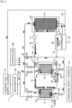
- Fig. 1 is a diagram illustrating the schematic configuration of a methane production device 1 according to a first embodiment.
- the methane production device 1 includes a first CO 2 separator 10, a second CO 2 separator 20, an exhaust gas supply flow path 30, a hydrogen supply flow path 40, a reactor 50, a material gas flow path 60, a heat medium flow path 70 and a controller 80.
- the first CO 2 separator 10 is a device configured to separate and recycle CO 2 from the exhaust gas and includes an adsorbent 11 placed inside thereof.
- the adsorbent 11 is a material having CO 2 storage (adsorption) capacity and is, for example, zeolite, active carbon or silica gel.
- the first CO 2 separator 10 also includes a hydrogen injector 12 provided inside of the first CO 2 separator 10 to inject hydrogen that is supplied through the hydrogen supply flow path 40, to the inside of the first CO 2 separator 10.
- the first CO 2 separator 10 is connected with the exhaust gas supply flow path 30, the material gas flow path 60 and a first discharge flow path 15.
- the second CO 2 separator 20 is a device having the identical configuration and the identical capacity to those of the first CO 2 separator 10 and includes an adsorbent 21 placed inside thereof.
- the adsorbent 21 is a material that is capable of storing CO 2 and has an equivalent storage capacity to that of the adsorbent 11.
- the second CO 2 separator 20 also includes a hydrogen injector 22 provided inside of the second CO 2 separator 20 to inject hydrogen that is supplied through the hydrogen supply flow path 40, to the inside of the second CO 2 separator 20.
- the second CO 2 separator 20 is connected with the exhaust gas supply flow path 30, the material gas flow path 60 and a second discharge flow path 25.
- the exhaust gas supply flow path 30 is a gas flow path provided to supply the exhaust gas that is discharged from an exhaust gas supply source 31, to the first CO 2 separator 10 and the second CO 2 separator 20 and is configured to include a plurality of gas pipings.
- the exhaust gas supply flow path 30 is provided with a dehydrator 32, a first exhaust gas supply valve 33 and a second exhaust gas supply valve 34.
- the exhaust gas supply source 31 is, for example, a combustion furnace at factory.
- the exhaust gas includes, for example, O 2 , N 2 and H 2 O other than CO 2 .
- the exhaust gas discharged from the exhaust gas supply source 31 is dehydrated by the dehydrator 32.
- the dehydrated exhaust gas is then supplied through the first exhaust gas supply valve 33 to the first CO 2 separator 10 and is also supplied through the second exhaust gas supply valve 34 to the second CO 2 separator 20.
- the first exhaust gas supply valve 33 and the second exhaust gas supply valve 34 are respectively controlled to be opened and closed by the controller 80.
- the exhaust gas supply flow path 30 is provided with a temperature sensor, a flow rate sensor and a CO 2 concentration sensor (not shown) configured to measure the temperature, the flow rate and the CO 2 concentration of the exhaust gas that is supplied to the first CO 2 separator 10 and to the second CO 2 separator 20.
- the hydrogen supply flow path 40 is a gas flow path provided to supply H 2 of a hydrogen supply source 41 to the first CO 2 separator 10, the second CO 2 separator 20 and the material gas flow path 60 and is configured to include a plurality of gas pipings.
- the hydrogen supply flow path 40 is provided with a first hydrogen supply valve 42, a second hydrogen supply valve 43 and a third hydrogen supply valve 44.
- the hydrogen supply source 41 is, for example, a water electrolyzer or a hydrogen tank. The following description is on the assumption that a water electrolyzer is employed as the hydrogen supply source 41.
- H 2 generated by the hydrogen supply source 41 is injected to the inside of the first CO 2 separator 10 when the first hydrogen supply valve 42 is opened, while being injected to the inside of the second CO 2 separator 20 when the second hydrogen supply valve 43 is opened. Furthermore, H 2 is added from a hydrogen adding portion 45 to the material gas flowing through the material gas flow path 60, when the third hydrogen supply valve 44 is opened.
- the first hydrogen supply valve 42, the second hydrogen supply valve 43 and the third hydrogen supply valve 44 are respectively controlled to be opened and closed.
- the hydrogen supply flow path 40 is provided with a temperature sensor and a flow rate sensor (not shown) configured to measure the temperature and the flow rate of the H 2 gas that is supplied to the first CO 2 separator 10, the second CO 2 separator 20 and the material gas flow path 60.
- the reactor 50 is a vessel configured to generate methane inside thereof by methanation reaction and includes a catalyst 51 placed inside thereof.
- the catalyst 51 includes a metal having methanation performance. Examples of the metal having the methanation performance include Ru and Ni.
- the reactor 50 is connected with the material gas flow path 60 and a reactive gaseous mixture flow path 91.
- the material gas including CO 2 and H 2 is supplied through the material gas flow path 60 into the reactor 50 and is subjected to the methanation reaction to generate methane.
- the reactive gaseous mixture including the generated methane is supplied through the reactive gaseous mixture flow path 91 to a heat exchanger 92.
- the heat exchanger 92 serves to separate H 2 O from the reactive gaseous mixture.
- the separated H 2 O is discharged through an H 2 O discharge flow path 93 to the outside.
- the remaining reactive gas after separation of H 2 O is supplied through a reactive gas flow path 94 to the exhaust gas supply source 31.
- the material gas flow path 60 is a gas flow path provided to supply the material gas that is delivered from the first CO 2 separator 10 and the second CO 2 separator 20 and includes H 2 and CO 2 , and is configured to include a plurality of gas pipings.
- the material gas flow path 60 is provided with a first material gas valve 61 and a second material gas valve 62.
- the first material gas valve 61 and the second material gas valve 62 are controlled to be opened and closed by the controller 80.
- the controller 80 controls the first material gas valve 61 to be opened and the second material gas valve 62 to be closed, in order to supply the material gas from the first CO 2 separator 10 to the reactor 50.
- the controller 80 controls the first material gas valve 61 to be closed and the second material gas valve 62 to be opened, in order to supply the material gas from the second CO 2 separator 20 to the reactor 50.
- the material gas flow path 60 is provided with a temperature sensor, a flow rate sensor and a CO 2 concentration sensor (not shown) configured to measure the temperature, the flow rate and the CO 2 concentration of the material gas flowing in the material gas flow path 60.
- the heat medium flow path 70 is a flow path which a heat medium of fluid such as oil (thermal fluid) flows in and is configured to supply the heat generated by the methanation reaction in the reactor 50 to the two CO2 separators (first CO2 separator 10 and second CO2 separator 20).
- the heat medium flow path 70 is provided with a first flow path changeover valve 71 and a second flow path changeover valve 72.
- the heat medium flow path 70 includes three flow paths (first heat medium flow path 73, second heat medium flow path 74 and third heat medium flow path 75) that are parted from one another by these two valves 71 and 72.
- the third heat medium flow path 75 is provided with a pump 76 and a temperature controller 77.
- the temperature controller 77 is a device configured to regulate the temperature of the heat medium.
- the temperature controller 77 adds a heat medium of ordinary temperature to regulate the temperature of the heat medium.
- the temperature controller 77 may use a heater or the like to heat the heat medium to the set temperature, along with regulation of the flow rate of the heat medium.
- the pump 76 and the temperature controller 77 are controlled by the controller 80.
- the first flow path changeover valve 71 is a three-way valve configured to change over the destination (the first heat medium flow path 73 or the second heat medium flow path 74) of the heat medium that is delivered from the third heat medium flow path 75 by the pump 76.
- the second flow path changeover valve 72 is operated in conjunction with the first flow path changeover valve 71 and is a three-way valve configured to change over the source (the first heat medium flow path 73 or the second heat medium flow path 74) of the heat medium that is to be returned to the third heat medium flow path 75.
- the changeover operations of the first flow path changeover valve 71 and the second flow path changeover valve 72 are controlled by the controller 80.
- the third heat medium flow path 75 includes a flow path that is arranged to go through inside of the reactor 50, and is configured to transmit the heat that is generated by the methanation reaction in the reactor 50, to the heat medium.
- the reactor 50 is configured by a double pipe.
- the catalyst 51 is placed in an inner tube thereof, and a flow path of the heat medium is formed between an outer tube and the inner tube thereof.
- the first heat medium flow path 73 includes a flow path that is arranged to go through inside of the first CO 2 separator 10, and is configured to supply the heat of the heat medium to the adsorbent 11.
- the second heat medium flow path 74 includes a flow path that is arranged to go through inside of the second CO 2 separator 20, and is configured to supply the heat of the heat medium to the adsorbent 21.
- Each of the first CO 2 separator 10 and the second CO 2 separator 20 is also configured by a double pipe and has a flow path of the heat medium that is formed between an outer tube and an inner tube thereof.
- the first CO 2 separator 10 is configured such that the flow direction of the heat medium inside of the first CO 2 separator 10 is a direction from a downstream side toward an upstream side of the gas flow direction when H 2 is injected from the hydrogen injector 12. According to the embodiment, the flow direction of the heat medium inside of the first CO 2 separator 10 is opposite to the injection direction of H 2 from the hydrogen injector 12.
- the second CO 2 separator 20 is configured such that the flow direction of the heat medium inside of the second CO 2 separator 20 is a direction from a downstream side toward an upstream side of the gas flow direction when H 2 is injected from the hydrogen injector 22.
- the flow direction of the heat medium inside of the second CO 2 separator 20 is opposite to the injection direction of H 2 from the hydrogen injector 22.
- the heat medium flow path 70 is provided with a temperature sensor and a flow rate sensor (not shown) configured to measure the temperature and the flow rate of the heat medium.
- the controller 80 is a computer configured to include a ROM, a RAM and a CPU and serves to control the entire methane production device 1.
- the controller 80 is electrically connected with the pump 76 and the temperature controller 77 as well as with the valves provided in the respective flow paths described above and the sensors (for example, temperature sensors, flow rate sensors and gas sensors) and controls the valves, the pump 76, the temperature controller 77 and the like, based on measurement values of the sensors and the like.
- a flow path control process performed by the controller 80 to control the gas flow path and the heat medium flow path will be described later.
- the controller 80 estimates an amount CO 2_IN of CO 2 flowing into each of the CO 2 separators 10 and 20, based on the measurement values of the various sensors (not shown) provided in the exhaust gas supply flow path 30.
- the controller 80 also estimates an amount CO 2_OUT of CO 2 taken out from each of the CO 2 separators 10 and 20, based on the measurement values of the various sensors (not shown) provided in the material gas flow path 60.
- FIG. 2 is a flowchart showing the flow path control process.
- Fig. 3 is a diagram illustrating the flow state of the gas and the like at steps S13 to S15.
- Fig. 4 is a diagram illustrating the flow state of gas and the like at steps S23 to S25.
- the controller 80 controls the first exhaust gas supply valve 33 to be opened and the second exhaust gas supply valve 34 to be closed at a specific timing during ordinary operation.
- the controller 80 simultaneously controls the first discharge valve 16 to be opened.
- Such control causes the dehydrated exhaust gas to be supplied from the exhaust gas supply source 31 to the first CO 2 separator 10.
- CO 2 included in the exhaust gas supplied to the first CO 2 separator 10 is stored in the adsorbent 11, and the remaining components of the exhaust gas are discharged through the first discharge flow path 15 to the outside.
- the controller 80 determines whether a condition to change over the supply destination of the exhaust gas (changeover condition) is satisfied (step S12).
- the changeover condition may be any condition that is allowed to estimate that the amount of CO 2 stored in the adsorbent 11 becomes equal to a predetermined amount.
- the controller 80 may determine whether the CO 2 concentration in the first discharge flow path 15 becomes higher than a reference value Th1 or may determine whether the amount CO 2_IN of CO 2 flowing into the first CO 2 separator 10 becomes greater than a reference value Th2.
- the controller 80 may determine whether the supply time of the exhaust gas becomes longer than a predetermined time period. The controller 80 keeps supplying the exhaust gas to the first CO 2 separator 10 until the changeover condition is satisfied (step S12: NO).
- step S12 When the changeover condition is satisfied (step S12: YES), the controller 80 controls the first exhaust gas supply valve 33 to be closed and the second exhaust gas supply valve 34 to be opened (step S13). Such control stops the supply of the exhaust gas to the first CO 2 separator 10 and starts the supply of the exhaust gas to the second CO 2 separator 20.
- the controller 80 simultaneously controls the second discharge valve 26 to be opened. This causes the dehydrated exhaust gas to be supplied from the exhaust gas supply source 31 to the second CO 2 separator 20 and causes CO 2 to be stored in the adsorbent 21, as shown in the second CO 2 separator 20 of Fig. 3 .
- the other components in the exhaust gas are discharged through the second discharge flow path 25 to the outside.
- the first CO 2 separator 10 stops receiving the supply of the exhaust gas and is in such a state that CO 2 is sufficiently stored in the adsorbent 11.
- the controller 80 controls the first flow path changeover valve 71 and the second flow path changeover valve 72 to change over the heat medium flow path to the first CO 2 separator 10-side and turns the pump 76 ON (step S14). This causes the heat medium to be circulated between the first heat medium flow path 73 and the third heat medium flow path 75, as shown in the heat medium flow path 70 of Fig. 3 .
- the controller 80 controls the temperature controller 77 such that the temperature of the heat medium flowing through the first CO 2 separator 10 becomes equal to a CO 2 desorption temperature from the adsorbent 11.
- the heat of reaction generated in the reactor 50 is supplied to the heat medium.
- the controller 80 accordingly causes the heat medium after regulation of the temperature by adding the heat medium of ordinary temperature in the temperature controller 77 to be supplied to the first CO 2 separator 10.
- the heat added by the temperature controller 77 may be supplied to the first CO 2 separator 10.
- the controller 80 controls the first hydrogen supply valve 42 to be opened (step S15). Simultaneously, the controller 80 controls the first discharge valve 16 to be closed and the first material gas valve 61 to be opened. Opening the first hydrogen supply valve 42 causes H 2 to be injected from the hydrogen injector 12 to the inside of the first CO 2 separator 10, as shown in the first CO 2 separator 10 of Fig. 3 . Injection of H 2 causes CO 2 in the gas phase desorbed from the adsorbent 11 to be purged out from inside of the first CO 2 separator 10 and to be discharged along with the injected H 2 to the material gas flow path 60.
- the controller 80 may control the injection amount H 2_IN of H 2 such as to maximize the amount CO 2_OUT by using, for example, the measurement values of the various sensors and a map.
- the controller 80 adds the remaining H 2 from the hydrogen adding portion 45, such that the material gas to be supplied to the reactor 50 has the stoichiometric ratio in the methanation reaction.
- the material gas having a ratio close to the stoichiometric ratio in the methanation reaction is then supplied to the reactor 50.
- the reactive gaseous mixture including methane generated inside of the reactor 50 is supplied through the reactive gaseous mixture flow path 91 to the heat exchanger 92.
- H 2 O separated in the heat exchanger 92 is discharged through the H 2 O discharge flow path 93 to the outside.
- the reactive gas after separation of H 2 O is supplied through the reactive gas flow path 94 to the exhaust gas supply source 31 as fuel gas.
- the second CO 2 separator 20 keeps receiving the supply of the exhaust gas.
- the controller 80 subsequently determines whether a condition to change over the supply destination of the exhaust gas (changeover condition) is satisfied (step S22).
- the changeover condition may be any condition that is allowed to estimate that the amount of CO 2 stored in the adsorbent 21 becomes equal to a predetermined amount.
- the controller 80 keeps supplying the exhaust gas to the second CO 2 separator 20 until the changeover condition is satisfied (step S22: NO).
- step S22 When the changeover condition is satisfied (step S22: YES), the controller 80 controls the first exhaust gas supply valve 33 to be opened and the second exhaust gas supply valve 34 to be closed (step S23). Such control restarts the supply of the exhaust gas to the first CO 2 separator 10 and stops the supply of the exhaust gas to the second CO 2 separator 20.
- the controller 80 simultaneously controls the first discharge valve 16 to be opened. This causes the dehydrated exhaust gas to be supplied from the exhaust gas supply source 31 to the first CO 2 separator 10 again and causes CO 2 to be stored in the adsorbent 11, as shown in the first CO 2 separator 10 of Fig. 4 .
- the second CO 2 separator 20 stops receiving the supply of the exhaust gas and is in such a state that CO 2 is sufficiently stored in the adsorbent 21.
- the controller 80 controls the first flow path changeover valve 71 and the second flow path changeover valve 72 to change over the heat medium flow path to the second CO 2 separator 20-side and turns the pump 76 ON (step S24). This causes the heat medium to be circulated between the second heat medium flow path 74 and the third heat medium flow path 75, as shown in the heat medium flow path 70 of Fig. 4 .
- the controller 80 controls the temperature controller 77 such that the temperature of the heat medium flowing through the second CO 2 separator 20 becomes equal to a CO 2 desorption temperature from the adsorbent 21, like step S14.
- the controller 80 controls the second hydrogen supply valve 43 to be opened (step S25). Simultaneously, the controller 80 controls the second discharge valve 26 to be closed and the second material gas valve 62 to be opened. Opening the second hydrogen supply valve 43 causes H 2 to be injected from the hydrogen injector 22 to the inside of the second CO 2 separator 20, as shown in the second CO 2 separator 20 of Fig. 4 . Injection of H 2 causes CO 2 in the gas phase desorbed from the adsorbent 21 to be purged out from inside of the second CO 2 separator 20 and to be discharged along with the injected H 2 to the material gas flow path 60.
- the controller 80 may control the injection amount H 2_IN of H 2 , like step S15.
- the material gas taken out from the inside of the second CO 2 separator 20 is supplied to the reactor 50.
- the reactive gaseous mixture including methane generated inside of the reactor 50 is supplied through the reactive gaseous mixture flow path 91 to the heat exchanger 92.
- the reactive gas after separation of H 2 O is supplied through the reactive gas flow path 94 to the exhaust gas supply source 31.
- the first CO 2 separator 10 keeps receiving the supply of the exhaust gas.
- the controller 80 then sequentially repeats the series of processing starting from step S12. The flow path control process is performed as described above.
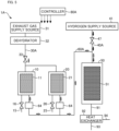
- Fig. 5 is a diagram illustrating the schematic configuration of a methane production device 1A according to Comparative Example 1. Exemplary advantageous effects of the embodiment are described, based on comparison between the prior art methane production device and the methane production device of the embodiment.
- the methane production device 1A of Comparative Example 1 is not provided with the heat medium flow path 70 or the hydrogen injectors 12 and 22, unlike the methane production device 1 of the embodiment (shown in Fig. 1 ).
- the methane production device 1A of Comparative Example 1 is, on the other hand, provided with a vacuum pump 64 configured to take out a gas inside of the first CO 2 separator 10 to a material gas flow path 60A.
- opening the first exhaust gas supply valve 33 and the first discharge valve 16 causes the dehydrated exhaust gas to be supplied from the exhaust gas supply source 31 to the first CO 2 separator 10.
- CO 2 included in the exhaust gas supplied to the first CO 2 separator 10 is stored in the adsorbent 11, and the remaining components of the exhaust gas are discharged through the first discharge flow path 15 to the outside.
- CO2 desorbed from the adsorbent 11 is taken out to the material gas flow path 60A by means of the vacuum pump 64.
- a hydrogen supply flow path 40A is connected with the material gas flow path 60A. Opening the hydrogen supply valve 47 causes H 2 to be supplied from the hydrogen supply source 41 to the material gas flow path 60A.
- CO 2 and H 2 flowing in the material gas flow path 60A are supplied to the reactor 50 and are subjected to methanation in the reactor 50.
- the methane production device 1A of Comparative Example 1 is not configured to supply the heat required for desorption of CO 2 from the adsorbent 11 through the heat medium flow path 70. This accordingly increases the energy externally applied for the purpose of recycle of CO 2 (CO 2 recycle energy).
- the methane production device 1 of the embodiment is, on the other hand, provided with the heat medium flow path 70 and thereby enables the thermal energy generated by the methanation reaction in the reactor 50 to be used as thermal energy required for desorption of CO 2 from the adsorbent 11. This reduces the CO 2 recycle energy.
- the methane production device 1A of Comparative Example 1 is configured such that CO 2 desorbed from the adsorbent 11 is taken out by means of the vacuum pump 64. This further increases the CO 2 recycle energy.
- the methane production device 1 of the embodiment is, on the other hand, configured such that H 2 is injected to the inside of the CO 2 separator 10 or 20 to purge out CO 2 . This configuration enhances the recycle rate of CO 2 and further reduces the CO 2 recycle energy.
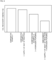
- Fig. 6 is a graph showing comparison of CO 2 recycle energy between the embodiment and Comparative Examples 1 to 3. More specifically, the graph of Fig. 6 shows CO 2 recycle energy of the methane production device 1A of Comparative Example 1 described above, CO 2 recycle energy of a methane production device of Comparative Example 2 provided with a configuration of supplying the heat of reaction generated in a reactor to a CO 2 separator like the heat medium flow path 70, CO 2 recycle energy of a methane production device of Comparative Example 3 provided with a configuration of injecting H 2 to a CO 2 separator to purge out CO 2 , and CO 2 recycle energy of the methane production device 1 of the embodiment provided with both these configurations.
- the reduced amount of the CO 2 recycle energy of the embodiment relative to the CO 2 recycle energy of Comparative Example 1 is greater than the total reduced amount of the CO 2 recycle energy of Comparative Examples 2 and 3 relative to the CO 2 recycle energy of Comparative Example 1.
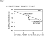
- Fig. 7 is a graph showing comparison of system efficiency between the embodiment and Comparative Example 1.
- the graph of Fig. 7 shows external power ratio [%] as abscissa and system efficiency [%] as ordinate.
- the external power denotes energy externally applied to the methane production device 1 and includes the CO 2 recycle energy described above and energies applied to the dehydrator 32 and the heat exchanger 92.
- the external power ratio denotes a ratio of the external power to a lower heat value (LHV) of hydrogen supplied as the material.
- the system efficiency denotes an index relating to the energy efficiency of the methane production device.
- the system efficiency is proportional to a conversion ratio and decreases with an increase in external power.
- the higher system efficiency results in more decreasing the cost of production of methane.
- the methane production device 1 of the embodiment employs the configuration of heat supply by the heat medium flow path 70 and the configuration of injection of H 2 into the CO 2 separator and thereby reduces the CO 2 recycle energy, compared with the methane production device 1A of Comparative Example 1. This accordingly reduces the external power ratio and enhances the system efficiency, compared with the methane production device 1A of Comparative Example 1.
- the methane production device 1 of the embodiment described above is configured to take out CO 2 from the CO 2 separators 10 and 20 by injecting H 2 to the inside of the CO 2 separators 10 and 20. This configuration reduces the external power such as a vacuum pump to take out CO 2 and enhances the system efficiency of the methane production device.
- the methane production device 1 of the embodiment is also configured to supply the heat of reaction generated in the reactor 50 to the CO 2 separators 10 and 20. This configuration reduces the external power to supply the thermal energy to the CO 2 separators 10 and 20 and further enhances the system efficiency of the methane production device.
- the CO 2 separators 10 and 20 are provided separately from the reactor 50. This configuration enables the heat of reaction generated in the reactor 50 to be supplied to appropriate positions in the CO 2 reactors 10 and 20. This enhances the CO 2 recycle rate.
- the methane production device 1 of the embodiment uses H 2 as the purge gas and thereby suppresses reduction of the CO 2 recycle rate. More specifically, the selectivity of CO 2 /H 2 is lower than the selectivity of CO 2 /N 2 in the adsorbents 11 and 21. This means that H 2 used as the purge gas is more unlikely to remain in the adsorbent than N 2 used as the purge gas. This accordingly suppresses interference with adsorption of CO 2 and suppresses reduction of the CO 2 recycle rate. Moreover, H 2 is the material used for the methanation reaction.
- the configuration of the embodiment may thus be implemented by simply moving an inlet of H 2 from a gas supply flow path to the reactor 50 to inside of the CO 2 separator. This configuration thus easily enhances the system efficiency without using any additional device.
- Fig. 8 is a diagram illustrating the internal configuration of the CO 2 separator 10 or 20.
- the CO 2 separator 10 or 20 is configured by a double pipe and has a flow path of the heat medium that is formed between an outer tube and an inner tube thereof.
- the flow direction of the heat medium is opposite to the flow direction of H 2 injected from the hydrogen injector 12 or 22.
- the supply direction of the exhaust gas is also opposite to the flow direction of H 2 injected from the hydrogen injector 12 or 22.
- H 2 /CO 2 mixed gas Injection of H 2 causes desorbed CO 2 to form H 2 /CO 2 mixed gas, which flows in the injection direction of H 2 (purge direction).
- the arrangement that the flow direction of the heat medium is opposite to the flow direction of the H 2 /CO 2 mixed gas increases the temperature on the downstream side of the H 2 /CO 2 mixed gas.
- This configuration suppresses CO 2 included in the H 2 /CO 2 mixed gas from being adsorbed again into the adsorbent 11 or 21 on the downstream side of the CO 2 separator 10 or 20. This enhances the recycle rate of CO 2 .
- the CO 2 separator 10 or 20 may be configured to change the inlet position of the heat medium.
- the CO 2 separator 10 or 20 may be configured to branch the flow of the heat medium and introduce the branched flows of the heat medium from a plurality of different positions.
- the CO 2 separator 10 or 20 may be configured to change the inlet position of the heat medium with time.
- the injection direction of H 2 is opposite to the supply direction of the exhaust gas, so that H 2 may be injected from a lower CO 2 partial pressure side toward a higher CO 2 partial pressure side. This enables CO 2 to be more efficiently taken out from the CO 2 separator 10 or 20.
- Fig. 9 is a diagram illustrating the schematic configuration of a methane production device 1B according to a second embodiment.
- the methane production device 1B of the second embodiment is not provided with a heat medium flow path which oil or the like is circulated through (heat medium flow path 70 of the first embodiment).
- a hydrogen supply flow path 40B of the second embodiment is, on the other hand, configured to use H 2 gas that is to be supplied to the CO 2 separators 10 and 20 as a heat medium and supply the heat of reaction generated in a reactor 50 to the CO 2 separators 10 and 20.
- the hydrogen supply flow path 40B also serves as a heat medium flow path according to the second embodiment.
- the hydrogen supply flow path 40B includes a flow path that is arranged to go through inside of the reactor 50, and is configured to transmit the heat of reaction generated in the reactor 50 to H 2 gas.
- the reactor 50 is configured by a double pipe.
- a catalyst 51 is placed in an inner tube thereof, and a flow path of H 2 gas is formed between an outer tube and the inner tube thereof.
- the hydrogen supply flow path 40B also includes flow paths that are arranged to go through inside of the two CO 2 separators 10 and 20, and is configured to supply the heat of the H 2 gas to the adsorbents 11 and 21.
- Each of the CO 2 separators 10 and 20 is also configured by a double pipe and has a flow path of the H 2 gas that is formed between an outer tube and an inner tube thereof.
- the H 2 gas flowing in the flow path formed between the outer tube and the inner tube of the CO 2 separator 10 or 20 is injected from the hydrogen injector 12 or 122 to the inside of the CO 2 separator 10 or 20.
- the hydrogen supply flow path 40B is further provided with a temperature controller 48.
- the temperature controller 48 is a device configured to regulate the temperature of the H 2 gas that is to be supplied to the CO 2 separators 10 and 20, and is controlled by a controller 80B.
- the H 2 gas of the hydrogen supply source 41 is heated in the reactor 50, is subjected to temperature regulation by the temperature controller 48, passes through the internal flow path of the first CO 2 separator 10 and is injected from the hydrogen injector 12 to the inside of the first CO 2 separator 10.
- the heated H 2 gas passes through the internal flow path of the first CO 2 separator 10 to increase the temperature of the adsorbent 11 and to cause CO 2 to be desorbed from the adsorbent 11.
- the H 2 gas of the hydrogen supply source 41 is heated in the reactor 50, is subjected to temperature regulation by the temperature controller 48, passes through the internal flow path of the second CO 2 separator 20 and is injected from the hydrogen injector 22 to the inside of the second CO 2 separator 20.
- the methane production device 1B of the second embodiment described above is configured to supply the thermal energy generated in the reactor 50 to the CO 2 separators 10 and 20 without the heat medium flow path which oil or the like is circulated through. Additionally, the methane production device 1B of the second embodiment does not need to be provided with a circulation device of the heat medium such as oil. This achieves downsizing of the methane production device.
- Fig. 10 is a diagram illustrating the schematic configuration of a methane production device 1C according to a third embodiment.
- the methane production device 1C of the third embodiment is not provided with the internal flow path that is formed inside of the CO 2 separator 10 or 20 to allow the H 2 gas to flow through.
- a hydrogen supply flow path 40C of the third embodiment is configured such that the H 2 gas heated by the heat of reaction generated in a reactor 50 is injected to the inside of the CO 2 separator 10 or 20.
- the H 2 gas of the hydrogen supply source 41 is heated in the reactor 50, is subjected to temperature regulation by the temperature controller 48 and is injected from the hydrogen injector 12 to the inside of the first CO 2 separator 10. Injecting the heated H 2 gas increases the temperature of the adsorbent 11 to cause CO 2 to be desorbed from the adsorbent 11 and causes the desorbed CO 2 to be discharged along with the injected H 2 from inside of the CO 2 separator 10 to a material gas flow path 60C.
- the H 2 gas of the hydrogen supply source 41 is heated in the reactor 50, is subjected to temperature regulation by the temperature controller 48 and is injected from the hydrogen injector 22 to the inside of the second CO 2 separator 20.
- the methane production device 1C of the third embodiment described above does not need to be provided with a circulation device of the heat medium such as oil. This achieves downsizing of the methane production device. Moreover, the methane production device 1C of the third embodiment is configured to inject the heated H 2 gas and thereby enables the thermal energy to be more efficiently supplied to the adsorbent.
- the methane production device 1C may be provided with a hydrogen injector configured to inject H 2 gas of ordinary temperature, in addition to the hydrogen injectors 12 and 22 configured to inject the heated H 2 gas, in the CO 2 separators 10 and 20. This configuration enables both the heated H 2 gas and the H 2 gas of ordinary temperature to be injected to the inside of the CO 2 separators 10 and 20 and enables the temperature of the H 2 gas to be adjusted to the temperature suitable for desorption of CO 2 .
- Fig. 11 is a diagram illustrating the schematic configuration of CO 2 separators 10D and reactors 50D according to a fourth embodiment.
- a methane production device 1D of the fourth embodiment is configured such that the CO 2 separator 10D and the reactor 50D are adjacent to each other across a partition member 55. More specifically, the methane production device 1D is configured by stacking a plurality of CO 2 separators 10D and a plurality of reactors 50D arranged across partition members 55. This configuration enables the heat of reaction generated in the respective reactors 50D to be directly supplied to the CO 2 separators 10D via the partition members 55.
- the methane production device 1D of the fourth embodiment described above uses the partition members 55 as the heat medium to supply the heat of reaction generated in the reactors 50D, to the CO 2 separators 10D.
- This simple configuration enables the heat of the methanation reaction generated in the reactors to be supplied to the CO 2 separators. This achieves downsizing of the methane production device.
- an amine-based absorbent that is one chemical absorbent may be provided inside of the CO 2 separators 10 and 20, in place of the adsorbents 11 and 12.
- This modified configuration may need the dehydrator 32 of the smaller capacity or may not need the dehydrator 32 at all.
- chemical absorption increases the desorption energy of CO 2 , compared with the adsorbent but enhances the system efficiency.
- the methane production device 1 of the first embodiment may use a higher hydrocarbon/ alcohol-generating catalyst (for example, Fe-based catalyst or otherwise Cu, Co or the like may be available) that is provided inside of the reactor 50, in place of the catalyst 51.
- This modification may be configured to employ the higher pressure as the reaction condition than the pressure condition employed for the catalyst having the methanation performance or may be configured to separate a liquid component from the generated gas and recirculate the remaining gas to an inlet of the reactor 50. The separated liquid component is used as a fuel.
- This modified configuration also enhances the system efficiency.
- the methane production device 1 of the first embodiment may be configured to supply the waste heat of the exhaust gas supply source 31 to the CO 2 separators 10 and 20.
- the waste heat may be used to heat the heat medium flowing in the heat medium flow path 70 or may be used to heat the H 2 gas supplied to the CO 2 separators 10 and 20.
- the methane production device 1 of the first embodiment may also be configured such that the waste heat of one of the CO 2 separators is supplied to the other CO 2 separator.
- Such modified configurations use the waste heat of the exhaust gas supply source 31 or the waste heat of the CO 2 separator as the desorption energy of CO 2 and thereby further enhance the system efficiency.
- the methane production device 1 of the first embodiment uses oil as the heat medium.
- the heat medium is, however, not limited to the oil but may be any substance that is capable of supplying heat.
- the heat medium may be, for example, a molten salt or a gas.
- the methane production device 1 may not be provided with the heat medium flow path 70. Even such modified configurations still enhance the system efficiency as long as H 2 is injected by the hydrogen injectors 12 and 22. It is, however, preferable that the methane production device 1 is provided with the heat medium flow path 70.
- the timing of increasing the temperature of the adsorbent by the heat medium and the timing of injection of H 2 are limited to those of the above embodiment.
- the temperature of the adsorbent may be increased after injection of H 2 , or these timings may be shifted arbitrarily.
- the temperature controller 77 may serve to heat the heat medium or may not serve to heat the heat medium.
- the temperature controller 77 may be configured not to heat the heat medium when the heat medium has already been heated by, for example, the heat of reaction generated in the reactor 50.
- the methane production device 1 of the first embodiment is provided with the two CO 2 separators 10 and 20.
- the methane production device 1 may, however, be provided with three or more CO 2 separators or may be provided with only one CO 2 separator.
- the first CO 2 separator 10 and the second CO 2 separator 20 have the identical configurations and identical capacities.
- the first CO 2 separator 10 and the second CO 2 separator 20 may have different configurations and different capacities.
- the methane production device 1 of the first embodiment may be provided with a vacuum pump configured to take out a gas inside of the first CO 2 separator 10 to the material gas flow path 60. Even in this modification, the configuration of the methane production device 1 of the first embodiment reduces the use of the vacuum pump and thereby suppresses an increase in the CO 2 recycle energy.
- the flow direction of the heat medium inside of the first CO 2 separator 10 is opposite to the injection direction of H 2 from the hydrogen injector 12.
- the flow direction of the heat medium inside of the first CO 2 separator 10 may, however, not be opposite to the injection direction of H 2 from the hydrogen injector 12. It is, however, preferable that the flow direction of the heat medium inside of the first CO 2 separator 10 is a direction from the downstream side toward the upstream side of the gas flow direction when H 2 is injected from the hydrogen injector 12. It is further preferable that the flow direction of the heat medium inside of the first CO 2 separator 10 is opposite to the injection direction of H 2 from the hydrogen injector 12.
Landscapes
- Chemical & Material Sciences (AREA)
- Chemical Kinetics & Catalysis (AREA)
- Oil, Petroleum & Natural Gas (AREA)
- Engineering & Computer Science (AREA)
- General Chemical & Material Sciences (AREA)
- Organic Chemistry (AREA)
- Analytical Chemistry (AREA)
- Organic Low-Molecular-Weight Compounds And Preparation Thereof (AREA)
- Hydrogen, Water And Hydrids (AREA)
- Catalysts (AREA)
- Low-Molecular Organic Synthesis Reactions Using Catalysts (AREA)
Claims (6)
- Methanherstellungsvorrichtung (1, 1B, 1C, 1D), die dazu konfiguriert ist, Methan aus Kohlenstoffdioxid und Wasserstoff herzustellen, die aufweist:einen Separator (10, 20), der mit einem Adsorptionsmittel (11, 21), das darin platziert ist und eine Kohlenstoffdioxid adsorbierende Leistung aufweist, vorgesehen ist und der dazu konfiguriert ist, Kohlenstoffdioxid von einem Gas zu trennen, das von einer Versorgungsquelle für das Kohlenstoffdioxid aufweisende Gas zugeführt wird;eine Wasserstoffeinspritzvorrichtung (12, 22), die dazu konfiguriert ist, Wasserstoff, der von einer Wasserstoffversorgungsquelle zugeführt wird, in das Innere des Separators (10, 20) einzuspritzen und so Kohlenstoffdioxid, das von dem Adsorptionsmittel (11, 21) desorbiert ist, aus dem Separator (10, 20) zu entnehmen;einen Reaktor (50), der mit einem Katalysator, der darin platziert ist und eine Methanisierungsleistung aufweist, vorgesehen ist und der dazu konfiguriert ist, eine Methanisierungsreaktion durch Verwendung eines Materialgases, das das aus dem Separator (10, 20) entnommene Kohlenstoffdioxid und den bei dem Einspritzen verwendeten Wasserstoff enthält, zu verursachen;einen Wasserstoffhinzufügungsabschnitt (45), der dazu konfiguriert ist, Wasserstoff, der von der Wasserstoffversorgungsquelle zugeführt wird, zu dem Materialgas, das an den Reaktor (50) geliefert wird, hinzuzufügen; undeine Steuereinrichtung (80), die dazu konfiguriert ist, eine Wasserstoffmenge, die durch den Wasserstoffhinzufügungsabschnitt (45) hinzugefügt wird, entsprechend eines Verhältnisses des aus dem Separator (10, 20) entnommenen Kohlenstoffdioxids zu dem von der Wasserstoffeinspritzvorrichtung (12, 22) eingespritzten Wasserstoff, zu steuern und ein Verhältnis von Wasserstoff und Kohlenstoffdioxid, die in dem Materialgas, das an den Reaktor (50) geliefert wird, enthalten sind, einzustellen.
- Methanherstellungsvorrichtung (1, 1B, 1C, 1D) nach Anspruch 1, die weiter aufweist:
einen Wärmelieferanten (70, 40B, 40C, 55), der dazu konfiguriert ist, Wärme, die in dem Reaktor durch die Methanisierungsreaktion erzeugt wird, an den Separator (10, 20) zu liefern. - Methanherstellungsvorrichtung (1) nach Anspruch 2,bei der der Wärmelieferant (70) dazu konfiguriert ist, ein Wärmemedium eines Fluids zwischen dem Reaktor (50) und dem Separator (10, 20) strömen zu lassen, und dadurch die in dem Reaktor (50) erzeugte Wärme an den Separator (10, 20) zu liefern, undeine Strömungsrichtung des Wärmemediums innerhalb des Separators (10, 20) eine Richtung ist, die von stromabwärts in Richtung stromaufwärts einer Gasströmungsrichtung verläuft, wenn Wasserstoff von der Wasserstoffeinspritzvorrichtung (12, 22) eingespritzt wird.
- Methanherstellungsvorrichtung (1B, 1C) nach Anspruch 2 oder 3,bei der der Wärmelieferant (70) dazu konfiguriert ist, Wasserstoff, der von der Wasserstoffversorgungsquelle zugeführt wird, als ein Wärmemedium zum Liefern der in dem Reaktor (50) erzeugten Wärme an den Separator (10, 20) zu verwenden, unddie Wasserstoffeinspritzvorrichtung (12, 22) dazu konfiguriert ist, Wasserstoff, der von dem Wärmelieferanten (70) zugeführt wird, in den Separator (10, 20) einzuspritzen.
- Methanherstellungsvorrichtung (1D) nach Anspruch 2,bei der der Reaktor (50) und der Separator (10, 20) benachbart zueinander angeordnet sind, undder Wärmelieferant (70) ein Element, das dafür vorgesehen ist, den Reaktor (50) und den Separator (10, 20) voneinander zu trennen, als ein Wärmemedium verwendet, um die in dem Reaktor (50) erzeugte Wärme an den Separator (10, 20) zu liefern.
- Methanherstellungsverfahren zur Methanherstellung aus Kohlenstoffdioxid und Wasserstoff, das aufweist:Liefern eines Gases, das Kohlenstoffdioxid enthält, an einen Separator, der mit einem Adsorptionsmittel, das darin platziert ist und eine Kohlenstoffdioxid adsorbierende Leistung aufweist, vorgesehen ist, und Trennen von Kohlenstoffdioxid von dem Gas;Einspritzen von Wasserstoff, der von einer Wasserstoffversorgungsquelle zugeführt wird, in den Separator und Entnehmen von Kohlenstoffdioxid, das von dem Adsorptionsmittel desorbiert ist, aus dem Separator; undLiefern eines Materialgases, das den aus dem Separator entnommenen Kohlenstoffdioxid und den bei dem Einspritzen verwendeten Wasserstoff enthält, an einen Reaktor, der mit einem Katalysator, der darin platziert ist und eine Methanisierungsleistung aufweist, vorgesehen ist, um eine Methanisierungsreaktion zu verursachen,bei dem das Verfahren weiter aufweist:Hinzufügen von Wasserstoff, der von der Wasserstoffversorgungsquelle zugeführt wird, zu dem Materialgas, das an den Reaktor geliefert wird, undSteuern einer Menge von Wasserstoff, die dem Materialgas, das an den Reaktor geliefert wird, hinzugefügt wird, entsprechend eines Verhältnisses des aus dem Separator entnommenen Kohlenstoffdioxids zu dem von der Wasserstoffeinspritzvorrichtung (12, 22) eingespritzten Wasserstoff, und Einstellen eines Verhältnisses von Wasserstoff und Kohlenstoffdioxid, die in dem Materialgas, das an den Reaktor (50) geliefert wird, enthalten sind.
Applications Claiming Priority (1)
| Application Number | Priority Date | Filing Date | Title |
|---|---|---|---|
| JP2018028331A JP6791177B2 (ja) | 2018-02-20 | 2018-02-20 | メタン製造装置、および、メタン製造方法 |
Publications (2)
| Publication Number | Publication Date |
|---|---|
| EP3530640A1 EP3530640A1 (de) | 2019-08-28 |
| EP3530640B1 true EP3530640B1 (de) | 2023-03-08 |
Family
ID=65443710
Family Applications (1)
| Application Number | Title | Priority Date | Filing Date |
|---|---|---|---|
| EP19157367.4A Active EP3530640B1 (de) | 2018-02-20 | 2019-02-15 | Vorrichtung zur methanherstellung und verfahren zur methanherstellung |
Country Status (2)
| Country | Link |
|---|---|
| EP (1) | EP3530640B1 (de) |
| JP (1) | JP6791177B2 (de) |
Cited By (2)
| Publication number | Priority date | Publication date | Assignee | Title |
|---|---|---|---|---|
| EP4524220A1 (de) * | 2023-09-18 | 2025-03-19 | Goodrich Corporation | Kohlendioxid (co2)-management in einem kohlenstoff-kohlenstoff (c/c)-vorformherstellungsverfahren |
| EP4582521A1 (de) * | 2024-01-02 | 2025-07-09 | Goodrich Corporation | Kohlenstoff-kohlenstoff (c/c)-system zur chemischen gasphaseninfiltration (cvi) zur herstellung von c/c-bremsen mit nahezu null kohlenstoffemission |
Families Citing this family (18)
| Publication number | Priority date | Publication date | Assignee | Title |
|---|---|---|---|---|
| JP6881393B2 (ja) * | 2018-06-08 | 2021-06-02 | 株式会社豊田中央研究所 | メタン製造装置、メタン製造装置の制御方法、および、メタン製造方法 |
| JP7443723B2 (ja) * | 2019-11-06 | 2024-03-06 | 株式会社豊田中央研究所 | 二酸化炭素回収装置、炭化水素生成装置、炭素循環システム、および、二酸化炭素回収方法 |
| JP7374742B2 (ja) * | 2019-12-06 | 2023-11-07 | 株式会社豊田中央研究所 | ガス供給装置、メタン製造装置、およびガス供給装置の制御方法 |
| JP7312688B2 (ja) * | 2019-12-13 | 2023-07-21 | 株式会社豊田中央研究所 | 炭化水素製造装置、炭化水素製造方法、および、コンピュータプログラム |
| KR102334163B1 (ko) * | 2020-01-30 | 2021-12-01 | 고등기술연구원연구조합 | 메탄 생성 장치 및 이의 제어 방법 |
| JP7291649B2 (ja) * | 2020-02-26 | 2023-06-15 | 株式会社豊田中央研究所 | 二酸化炭素回収装置、炭化水素製造装置、および二酸化炭素回収方法 |
| JP7452231B2 (ja) * | 2020-04-30 | 2024-03-19 | 株式会社豊田中央研究所 | 二酸化炭素吸着材、二酸化炭素回収装置、および、炭化水素生成システム |
| JP7476663B2 (ja) * | 2020-05-20 | 2024-05-01 | 株式会社豊田中央研究所 | 水電解用除湿システム、メタン製造システム、および水電解用除湿システムの制御方法 |
| JP7487590B2 (ja) * | 2020-07-10 | 2024-05-21 | 株式会社豊田中央研究所 | 二酸化炭素回収装置及び二酸化炭素回収方法 |
| JP7338577B2 (ja) * | 2020-07-10 | 2023-09-05 | 株式会社豊田中央研究所 | 二酸化炭素回収装置及び二酸化炭素回収方法 |
| CN111979004B (zh) * | 2020-08-06 | 2021-08-17 | 中石化石油机械股份有限公司研究院 | 一种基于高压的节流天然气脱水系统 |
| JP7407673B2 (ja) * | 2020-08-11 | 2024-01-04 | 株式会社豊田中央研究所 | 炭化水素製造システム |
| JP7655722B2 (ja) * | 2020-12-21 | 2025-04-02 | 株式会社豊田中央研究所 | ガス分離システム、および炭化水素製造システム |
| JP7721286B2 (ja) * | 2021-03-08 | 2025-08-12 | 株式会社豊田中央研究所 | 二酸化炭素循環システム、および、ガス乾燥用吸着材 |
| JP7689861B2 (ja) * | 2021-04-14 | 2025-06-09 | 株式会社豊田中央研究所 | 二酸化炭素回収制御装置、二酸化炭素回収装置、炭化水素製造装置、二酸化炭素回収方法、およびプログラム |
| JP7716237B2 (ja) * | 2021-06-09 | 2025-07-31 | 株式会社豊田中央研究所 | 二酸化炭素回収装置 |
| JP2024018475A (ja) * | 2022-07-29 | 2024-02-08 | 株式会社日立製作所 | 炭化水素製造装置および炭化水素製造方法 |
| CN119486792A (zh) | 2022-10-12 | 2025-02-18 | 瓦克化学股份公司 | 生产氢气与二氧化碳的气体混合物 |
Family Cites Families (8)
| Publication number | Priority date | Publication date | Assignee | Title |
|---|---|---|---|---|
| JPH1146460A (ja) | 1997-03-14 | 1999-02-16 | Toshiba Corp | 電力貯蔵システム |
| JP2009077457A (ja) | 2007-09-18 | 2009-04-09 | Tokyo Gas Co Ltd | 分散型電源の運転システムおよびその運転方法 |
| JP2009269983A (ja) | 2008-05-02 | 2009-11-19 | Yoshiro Nakamatsu | 二酸化炭素消滅燃料費節約装置 |
| WO2011108546A1 (ja) | 2010-03-02 | 2011-09-09 | Jfeスチール株式会社 | 高炉の操業方法、製鉄所の操業方法、および酸化炭素含有ガスの利用方法 |
| CN102660340B (zh) | 2012-04-24 | 2014-06-11 | 武汉凯迪工程技术研究总院有限公司 | 利用过剩电能将烟气中的二氧化碳转化成天然气的工艺及设备 |
| CN104152197B (zh) * | 2013-05-14 | 2017-02-08 | 中国科学院大连化学物理研究所 | 一种密闭空间内co2富集及甲烷化工艺与反应器 |
| DE102013022021B4 (de) * | 2013-12-20 | 2018-02-15 | Bruno Kolb | Verfahren zur Methanisierung von Kohlendioxid aus Gasgemischen nach Abtrennung durch selektive reversible Adsorption |
| US20170306825A1 (en) | 2014-11-13 | 2017-10-26 | Hitachi, Ltd. | Co2 recovery device of internal combustion engine |
-
2018
- 2018-02-20 JP JP2018028331A patent/JP6791177B2/ja active Active
-
2019
- 2019-02-15 EP EP19157367.4A patent/EP3530640B1/de active Active
Cited By (2)
| Publication number | Priority date | Publication date | Assignee | Title |
|---|---|---|---|---|
| EP4524220A1 (de) * | 2023-09-18 | 2025-03-19 | Goodrich Corporation | Kohlendioxid (co2)-management in einem kohlenstoff-kohlenstoff (c/c)-vorformherstellungsverfahren |
| EP4582521A1 (de) * | 2024-01-02 | 2025-07-09 | Goodrich Corporation | Kohlenstoff-kohlenstoff (c/c)-system zur chemischen gasphaseninfiltration (cvi) zur herstellung von c/c-bremsen mit nahezu null kohlenstoffemission |
Also Published As
| Publication number | Publication date |
|---|---|
| JP6791177B2 (ja) | 2020-11-25 |
| EP3530640A1 (de) | 2019-08-28 |
| JP2019142806A (ja) | 2019-08-29 |
Similar Documents
| Publication | Publication Date | Title |
|---|---|---|
| EP3530640A1 (de) | Vorrichtung zur methanherstellung und verfahren zur methanherstellung | |
| US10597293B2 (en) | Operation method for hydrogen production apparatus, and hydrogen production apparatus | |
| JP7452231B2 (ja) | 二酸化炭素吸着材、二酸化炭素回収装置、および、炭化水素生成システム | |
| US8112987B2 (en) | Process for reducing NOx emissions from engine exhaust using LNT and SCR components | |
| JP2021035909A (ja) | メタン製造方法及び設備 | |
| EP3310880A1 (de) | Verfahren zur umwandlung von co2 in brennstoff an bord eines fahrzeuges und vorrichtung dafür | |
| WO2003094273A1 (en) | Fuel cell power generation system and method for operating the same | |
| US20250243053A1 (en) | Systems and methods of processing ammonia | |
| CA3244903A1 (en) | ELECTROLYTIC REGENERATION OF A CO2-RICH ALKALINE ABSORBENT FOR CO2 RECOVERY | |
| US11931712B2 (en) | Fuel synthesis device | |
| CN115172789B (zh) | 回收利用系统和回收利用方法、回收方法和车辆 | |
| JP4394038B2 (ja) | ガス分離装置、ガス分離方法およびガスエンジンコジェネレーションシステム | |
| JP2020163246A (ja) | 二酸化炭素回収装置、炭化水素製造装置、および、二酸化炭素回収方法 | |
| KR101720577B1 (ko) | 산소전달물질을 이용한 고정상 개질 시스템 및 방법 | |
| US7767181B2 (en) | System and method for ammonia production | |
| KR20160042488A (ko) | 전기자동차 배터리 충전용 연료전지 시스템 | |
| WO2021010031A1 (ja) | 燃料改質システム | |
| CN102807199B (zh) | 氩气的提纯方法及提纯装置 | |
| EP4527986A2 (de) | Kathodengas-zufuhrsystem und kohlenstoff-recycling-system | |
| JP2005298265A (ja) | 水素生成装置 | |
| CN113614026B (zh) | 氢制造装置的运转方法及氢制造装置 | |
| CN120885015A (zh) | 直接空气捕集耦合原位催化转化制备绿色燃料的系统和方法 | |
| KR20240164494A (ko) | 개질 처리 장치 | |
| JP2005256708A (ja) | 燃料供給システム | |
| CN120662098A (zh) | 水合物促进剂调控、气体分离方法及装置和气体分离设备 |
Legal Events
| Date | Code | Title | Description |
|---|---|---|---|
| PUAI | Public reference made under article 153(3) epc to a published international application that has entered the european phase |
Free format text: ORIGINAL CODE: 0009012 |
|
| STAA | Information on the status of an ep patent application or granted ep patent |
Free format text: STATUS: REQUEST FOR EXAMINATION WAS MADE |
|
| 17P | Request for examination filed |
Effective date: 20190215 |
|
| AK | Designated contracting states |
Kind code of ref document: A1 Designated state(s): AL AT BE BG CH CY CZ DE DK EE ES FI FR GB GR HR HU IE IS IT LI LT LU LV MC MK MT NL NO PL PT RO RS SE SI SK SM TR |
|
| AX | Request for extension of the european patent |
Extension state: BA ME |
|
| STAA | Information on the status of an ep patent application or granted ep patent |
Free format text: STATUS: EXAMINATION IS IN PROGRESS |
|
| 17Q | First examination report despatched |
Effective date: 20211124 |
|
| GRAP | Despatch of communication of intention to grant a patent |
Free format text: ORIGINAL CODE: EPIDOSNIGR1 |
|
| STAA | Information on the status of an ep patent application or granted ep patent |
Free format text: STATUS: GRANT OF PATENT IS INTENDED |
|
| INTG | Intention to grant announced |
Effective date: 20221010 |
|
| GRAS | Grant fee paid |
Free format text: ORIGINAL CODE: EPIDOSNIGR3 |
|
| GRAA | (expected) grant |
Free format text: ORIGINAL CODE: 0009210 |
|
| STAA | Information on the status of an ep patent application or granted ep patent |
Free format text: STATUS: THE PATENT HAS BEEN GRANTED |
|
| AK | Designated contracting states |
Kind code of ref document: B1 Designated state(s): AL AT BE BG CH CY CZ DE DK EE ES FI FR GB GR HR HU IE IS IT LI LT LU LV MC MK MT NL NO PL PT RO RS SE SI SK SM TR |
|
| REG | Reference to a national code |
Ref country code: CH Ref legal event code: EP Ref country code: AT Ref legal event code: REF Ref document number: 1552503 Country of ref document: AT Kind code of ref document: T Effective date: 20230315 |
|
| REG | Reference to a national code |
Ref country code: IE Ref legal event code: FG4D |
|
| REG | Reference to a national code |
Ref country code: DE Ref legal event code: R096 Ref document number: 602019026041 Country of ref document: DE |
|
| REG | Reference to a national code |
Ref country code: LT Ref legal event code: MG9D |
|
| REG | Reference to a national code |
Ref country code: NL Ref legal event code: MP Effective date: 20230308 |
|
| PG25 | Lapsed in a contracting state [announced via postgrant information from national office to epo] |
Ref country code: RS Free format text: LAPSE BECAUSE OF FAILURE TO SUBMIT A TRANSLATION OF THE DESCRIPTION OR TO PAY THE FEE WITHIN THE PRESCRIBED TIME-LIMIT Effective date: 20230308 Ref country code: NO Free format text: LAPSE BECAUSE OF FAILURE TO SUBMIT A TRANSLATION OF THE DESCRIPTION OR TO PAY THE FEE WITHIN THE PRESCRIBED TIME-LIMIT Effective date: 20230608 Ref country code: LV Free format text: LAPSE BECAUSE OF FAILURE TO SUBMIT A TRANSLATION OF THE DESCRIPTION OR TO PAY THE FEE WITHIN THE PRESCRIBED TIME-LIMIT Effective date: 20230308 Ref country code: LT Free format text: LAPSE BECAUSE OF FAILURE TO SUBMIT A TRANSLATION OF THE DESCRIPTION OR TO PAY THE FEE WITHIN THE PRESCRIBED TIME-LIMIT Effective date: 20230308 Ref country code: HR Free format text: LAPSE BECAUSE OF FAILURE TO SUBMIT A TRANSLATION OF THE DESCRIPTION OR TO PAY THE FEE WITHIN THE PRESCRIBED TIME-LIMIT Effective date: 20230308 Ref country code: ES Free format text: LAPSE BECAUSE OF FAILURE TO SUBMIT A TRANSLATION OF THE DESCRIPTION OR TO PAY THE FEE WITHIN THE PRESCRIBED TIME-LIMIT Effective date: 20230308 |
|
| REG | Reference to a national code |
Ref country code: AT Ref legal event code: MK05 Ref document number: 1552503 Country of ref document: AT Kind code of ref document: T Effective date: 20230308 |
|
| PG25 | Lapsed in a contracting state [announced via postgrant information from national office to epo] |
Ref country code: SE Free format text: LAPSE BECAUSE OF FAILURE TO SUBMIT A TRANSLATION OF THE DESCRIPTION OR TO PAY THE FEE WITHIN THE PRESCRIBED TIME-LIMIT Effective date: 20230308 Ref country code: NL Free format text: LAPSE BECAUSE OF FAILURE TO SUBMIT A TRANSLATION OF THE DESCRIPTION OR TO PAY THE FEE WITHIN THE PRESCRIBED TIME-LIMIT Effective date: 20230308 Ref country code: GR Free format text: LAPSE BECAUSE OF FAILURE TO SUBMIT A TRANSLATION OF THE DESCRIPTION OR TO PAY THE FEE WITHIN THE PRESCRIBED TIME-LIMIT Effective date: 20230609 Ref country code: FI Free format text: LAPSE BECAUSE OF FAILURE TO SUBMIT A TRANSLATION OF THE DESCRIPTION OR TO PAY THE FEE WITHIN THE PRESCRIBED TIME-LIMIT Effective date: 20230308 |
|
| PG25 | Lapsed in a contracting state [announced via postgrant information from national office to epo] |
Ref country code: SM Free format text: LAPSE BECAUSE OF FAILURE TO SUBMIT A TRANSLATION OF THE DESCRIPTION OR TO PAY THE FEE WITHIN THE PRESCRIBED TIME-LIMIT Effective date: 20230308 Ref country code: RO Free format text: LAPSE BECAUSE OF FAILURE TO SUBMIT A TRANSLATION OF THE DESCRIPTION OR TO PAY THE FEE WITHIN THE PRESCRIBED TIME-LIMIT Effective date: 20230308 Ref country code: PT Free format text: LAPSE BECAUSE OF FAILURE TO SUBMIT A TRANSLATION OF THE DESCRIPTION OR TO PAY THE FEE WITHIN THE PRESCRIBED TIME-LIMIT Effective date: 20230710 Ref country code: EE Free format text: LAPSE BECAUSE OF FAILURE TO SUBMIT A TRANSLATION OF THE DESCRIPTION OR TO PAY THE FEE WITHIN THE PRESCRIBED TIME-LIMIT Effective date: 20230308 Ref country code: CZ Free format text: LAPSE BECAUSE OF FAILURE TO SUBMIT A TRANSLATION OF THE DESCRIPTION OR TO PAY THE FEE WITHIN THE PRESCRIBED TIME-LIMIT Effective date: 20230308 Ref country code: AT Free format text: LAPSE BECAUSE OF FAILURE TO SUBMIT A TRANSLATION OF THE DESCRIPTION OR TO PAY THE FEE WITHIN THE PRESCRIBED TIME-LIMIT Effective date: 20230308 |
|
| PG25 | Lapsed in a contracting state [announced via postgrant information from national office to epo] |
Ref country code: SK Free format text: LAPSE BECAUSE OF FAILURE TO SUBMIT A TRANSLATION OF THE DESCRIPTION OR TO PAY THE FEE WITHIN THE PRESCRIBED TIME-LIMIT Effective date: 20230308 Ref country code: PL Free format text: LAPSE BECAUSE OF FAILURE TO SUBMIT A TRANSLATION OF THE DESCRIPTION OR TO PAY THE FEE WITHIN THE PRESCRIBED TIME-LIMIT Effective date: 20230308 Ref country code: IS Free format text: LAPSE BECAUSE OF FAILURE TO SUBMIT A TRANSLATION OF THE DESCRIPTION OR TO PAY THE FEE WITHIN THE PRESCRIBED TIME-LIMIT Effective date: 20230708 |
|
| REG | Reference to a national code |
Ref country code: DE Ref legal event code: R097 Ref document number: 602019026041 Country of ref document: DE |
|
| PLBE | No opposition filed within time limit |
Free format text: ORIGINAL CODE: 0009261 |
|
| STAA | Information on the status of an ep patent application or granted ep patent |
Free format text: STATUS: NO OPPOSITION FILED WITHIN TIME LIMIT |
|
| PG25 | Lapsed in a contracting state [announced via postgrant information from national office to epo] |
Ref country code: SI Free format text: LAPSE BECAUSE OF FAILURE TO SUBMIT A TRANSLATION OF THE DESCRIPTION OR TO PAY THE FEE WITHIN THE PRESCRIBED TIME-LIMIT Effective date: 20230308 Ref country code: DK Free format text: LAPSE BECAUSE OF FAILURE TO SUBMIT A TRANSLATION OF THE DESCRIPTION OR TO PAY THE FEE WITHIN THE PRESCRIBED TIME-LIMIT Effective date: 20230308 |
|
| 26N | No opposition filed |
Effective date: 20231211 |
|
| PG25 | Lapsed in a contracting state [announced via postgrant information from national office to epo] |
Ref country code: IT Free format text: LAPSE BECAUSE OF FAILURE TO SUBMIT A TRANSLATION OF THE DESCRIPTION OR TO PAY THE FEE WITHIN THE PRESCRIBED TIME-LIMIT Effective date: 20230308 |
|
| PG25 | Lapsed in a contracting state [announced via postgrant information from national office to epo] |
Ref country code: MC Free format text: LAPSE BECAUSE OF FAILURE TO SUBMIT A TRANSLATION OF THE DESCRIPTION OR TO PAY THE FEE WITHIN THE PRESCRIBED TIME-LIMIT Effective date: 20230308 |
|
| REG | Reference to a national code |
Ref country code: CH Ref legal event code: PL |
|
| PG25 | Lapsed in a contracting state [announced via postgrant information from national office to epo] |
Ref country code: LU Free format text: LAPSE BECAUSE OF NON-PAYMENT OF DUE FEES Effective date: 20240215 |
|
| PG25 | Lapsed in a contracting state [announced via postgrant information from national office to epo] |
Ref country code: CH Free format text: LAPSE BECAUSE OF NON-PAYMENT OF DUE FEES Effective date: 20240229 |
|
| GBPC | Gb: european patent ceased through non-payment of renewal fee |
Effective date: 20240215 |
|
| PG25 | Lapsed in a contracting state [announced via postgrant information from national office to epo] |
Ref country code: LU Free format text: LAPSE BECAUSE OF NON-PAYMENT OF DUE FEES Effective date: 20240215 Ref country code: CH Free format text: LAPSE BECAUSE OF NON-PAYMENT OF DUE FEES Effective date: 20240229 |
|
| PG25 | Lapsed in a contracting state [announced via postgrant information from national office to epo] |
Ref country code: BG Free format text: LAPSE BECAUSE OF FAILURE TO SUBMIT A TRANSLATION OF THE DESCRIPTION OR TO PAY THE FEE WITHIN THE PRESCRIBED TIME-LIMIT Effective date: 20230308 |
|
| PG25 | Lapsed in a contracting state [announced via postgrant information from national office to epo] |
Ref country code: BG Free format text: LAPSE BECAUSE OF FAILURE TO SUBMIT A TRANSLATION OF THE DESCRIPTION OR TO PAY THE FEE WITHIN THE PRESCRIBED TIME-LIMIT Effective date: 20230308 |
|
| REG | Reference to a national code |
Ref country code: BE Ref legal event code: MM Effective date: 20240229 |
|
| PG25 | Lapsed in a contracting state [announced via postgrant information from national office to epo] |
Ref country code: BE Free format text: LAPSE BECAUSE OF NON-PAYMENT OF DUE FEES Effective date: 20240229 |
|
| PG25 | Lapsed in a contracting state [announced via postgrant information from national office to epo] |
Ref country code: GB Free format text: LAPSE BECAUSE OF NON-PAYMENT OF DUE FEES Effective date: 20240215 |
|
| PG25 | Lapsed in a contracting state [announced via postgrant information from national office to epo] |
Ref country code: FR Free format text: LAPSE BECAUSE OF NON-PAYMENT OF DUE FEES Effective date: 20240229 |
|
| PG25 | Lapsed in a contracting state [announced via postgrant information from national office to epo] |
Ref country code: IE Free format text: LAPSE BECAUSE OF NON-PAYMENT OF DUE FEES Effective date: 20240215 |
|
| PG25 | Lapsed in a contracting state [announced via postgrant information from national office to epo] |
Ref country code: IE Free format text: LAPSE BECAUSE OF NON-PAYMENT OF DUE FEES Effective date: 20240215 Ref country code: GB Free format text: LAPSE BECAUSE OF NON-PAYMENT OF DUE FEES Effective date: 20240215 Ref country code: FR Free format text: LAPSE BECAUSE OF NON-PAYMENT OF DUE FEES Effective date: 20240229 Ref country code: BE Free format text: LAPSE BECAUSE OF NON-PAYMENT OF DUE FEES Effective date: 20240229 |
|
| PG25 | Lapsed in a contracting state [announced via postgrant information from national office to epo] |
Ref country code: CY Free format text: LAPSE BECAUSE OF FAILURE TO SUBMIT A TRANSLATION OF THE DESCRIPTION OR TO PAY THE FEE WITHIN THE PRESCRIBED TIME-LIMIT; INVALID AB INITIO Effective date: 20190215 |
|
| PG25 | Lapsed in a contracting state [announced via postgrant information from national office to epo] |
Ref country code: HU Free format text: LAPSE BECAUSE OF FAILURE TO SUBMIT A TRANSLATION OF THE DESCRIPTION OR TO PAY THE FEE WITHIN THE PRESCRIBED TIME-LIMIT; INVALID AB INITIO Effective date: 20190215 |
|
| PG25 | Lapsed in a contracting state [announced via postgrant information from national office to epo] |
Ref country code: TR Free format text: LAPSE BECAUSE OF FAILURE TO SUBMIT A TRANSLATION OF THE DESCRIPTION OR TO PAY THE FEE WITHIN THE PRESCRIBED TIME-LIMIT Effective date: 20230308 |
|
| PGFP | Annual fee paid to national office [announced via postgrant information from national office to epo] |
Ref country code: DE Payment date: 20251230 Year of fee payment: 8 |