EP3530407A1 - Laufbahnrillenbearbeitungsverfahren, lager, kugelgewindevorrichtung, maschine und fahrzeugherstellungsverfahren - Google Patents
Laufbahnrillenbearbeitungsverfahren, lager, kugelgewindevorrichtung, maschine und fahrzeugherstellungsverfahren Download PDFInfo
- Publication number
- EP3530407A1 EP3530407A1 EP17861832.8A EP17861832A EP3530407A1 EP 3530407 A1 EP3530407 A1 EP 3530407A1 EP 17861832 A EP17861832 A EP 17861832A EP 3530407 A1 EP3530407 A1 EP 3530407A1
- Authority
- EP
- European Patent Office
- Prior art keywords
- ball screw
- processed
- raceway groove
- processing
- groove
- Prior art date
- Legal status (The legal status is an assumption and is not a legal conclusion. Google has not performed a legal analysis and makes no representation as to the accuracy of the status listed.)
- Withdrawn
Links
Images


Classifications
-
- B—PERFORMING OPERATIONS; TRANSPORTING
- B23—MACHINE TOOLS; METAL-WORKING NOT OTHERWISE PROVIDED FOR
- B23G—THREAD CUTTING; WORKING OF SCREWS, BOLT HEADS, OR NUTS, IN CONJUNCTION THEREWITH
- B23G1/00—Thread cutting; Automatic machines specially designed therefor
- B23G1/22—Machines specially designed for operating on pipes or tubes
-
- B—PERFORMING OPERATIONS; TRANSPORTING
- B23—MACHINE TOOLS; METAL-WORKING NOT OTHERWISE PROVIDED FOR
- B23P—METAL-WORKING NOT OTHERWISE PROVIDED FOR; COMBINED OPERATIONS; UNIVERSAL MACHINE TOOLS
- B23P15/00—Making specific metal objects by operations not covered by a single other subclass or a group in this subclass
- B23P15/003—Making specific metal objects by operations not covered by a single other subclass or a group in this subclass bearings
-
- B—PERFORMING OPERATIONS; TRANSPORTING
- B23—MACHINE TOOLS; METAL-WORKING NOT OTHERWISE PROVIDED FOR
- B23P—METAL-WORKING NOT OTHERWISE PROVIDED FOR; COMBINED OPERATIONS; UNIVERSAL MACHINE TOOLS
- B23P9/00—Treating or finishing surfaces mechanically, with or without calibrating, primarily to resist wear or impact, e.g. smoothing or roughening turbine blades or bearings; Features of such surfaces not otherwise provided for, their treatment being unspecified
- B23P9/04—Treating or finishing by hammering or applying repeated pressure
-
- B—PERFORMING OPERATIONS; TRANSPORTING
- B24—GRINDING; POLISHING
- B24B—MACHINES, DEVICES, OR PROCESSES FOR GRINDING OR POLISHING; DRESSING OR CONDITIONING OF ABRADING SURFACES; FEEDING OF GRINDING, POLISHING, OR LAPPING AGENTS
- B24B19/00—Single-purpose machines or devices for particular grinding operations not covered by any other main group
- B24B19/02—Single-purpose machines or devices for particular grinding operations not covered by any other main group for grinding grooves, e.g. on shafts, in casings, in tubes, homokinetic joint elements
- B24B19/022—Single-purpose machines or devices for particular grinding operations not covered by any other main group for grinding grooves, e.g. on shafts, in casings, in tubes, homokinetic joint elements for helicoidal grooves
-
- B—PERFORMING OPERATIONS; TRANSPORTING
- B24—GRINDING; POLISHING
- B24B—MACHINES, DEVICES, OR PROCESSES FOR GRINDING OR POLISHING; DRESSING OR CONDITIONING OF ABRADING SURFACES; FEEDING OF GRINDING, POLISHING, OR LAPPING AGENTS
- B24B19/00—Single-purpose machines or devices for particular grinding operations not covered by any other main group
- B24B19/02—Single-purpose machines or devices for particular grinding operations not covered by any other main group for grinding grooves, e.g. on shafts, in casings, in tubes, homokinetic joint elements
- B24B19/06—Single-purpose machines or devices for particular grinding operations not covered by any other main group for grinding grooves, e.g. on shafts, in casings, in tubes, homokinetic joint elements for grinding races, e.g. roller races
-
- B—PERFORMING OPERATIONS; TRANSPORTING
- B24—GRINDING; POLISHING
- B24B—MACHINES, DEVICES, OR PROCESSES FOR GRINDING OR POLISHING; DRESSING OR CONDITIONING OF ABRADING SURFACES; FEEDING OF GRINDING, POLISHING, OR LAPPING AGENTS
- B24B39/00—Burnishing machines or devices, i.e. requiring pressure members for compacting the surface zone; Accessories therefor
- B24B39/02—Burnishing machines or devices, i.e. requiring pressure members for compacting the surface zone; Accessories therefor designed for working internal surfaces of revolution
- B24B39/023—Burnishing machines or devices, i.e. requiring pressure members for compacting the surface zone; Accessories therefor designed for working internal surfaces of revolution the working tool being composed of a plurality of working rolls or balls
-
- F—MECHANICAL ENGINEERING; LIGHTING; HEATING; WEAPONS; BLASTING
- F16—ENGINEERING ELEMENTS AND UNITS; GENERAL MEASURES FOR PRODUCING AND MAINTAINING EFFECTIVE FUNCTIONING OF MACHINES OR INSTALLATIONS; THERMAL INSULATION IN GENERAL
- F16C—SHAFTS; FLEXIBLE SHAFTS; ELEMENTS OR CRANKSHAFT MECHANISMS; ROTARY BODIES OTHER THAN GEARING ELEMENTS; BEARINGS
- F16C33/00—Parts of bearings; Special methods for making bearings or parts thereof
- F16C33/30—Parts of ball or roller bearings
- F16C33/58—Raceways; Race rings
- F16C33/64—Special methods of manufacture
-
- F—MECHANICAL ENGINEERING; LIGHTING; HEATING; WEAPONS; BLASTING
- F16—ENGINEERING ELEMENTS AND UNITS; GENERAL MEASURES FOR PRODUCING AND MAINTAINING EFFECTIVE FUNCTIONING OF MACHINES OR INSTALLATIONS; THERMAL INSULATION IN GENERAL
- F16H—GEARING
- F16H25/00—Gearings comprising primarily only cams, cam-followers and screw-and-nut mechanisms
- F16H25/18—Gearings comprising primarily only cams, cam-followers and screw-and-nut mechanisms for conveying or interconverting oscillating or reciprocating motions
- F16H25/20—Screw mechanisms
- F16H25/24—Elements essential to such mechanisms, e.g. screws, nuts
-
- F—MECHANICAL ENGINEERING; LIGHTING; HEATING; WEAPONS; BLASTING
- F16—ENGINEERING ELEMENTS AND UNITS; GENERAL MEASURES FOR PRODUCING AND MAINTAINING EFFECTIVE FUNCTIONING OF MACHINES OR INSTALLATIONS; THERMAL INSULATION IN GENERAL
- F16C—SHAFTS; FLEXIBLE SHAFTS; ELEMENTS OR CRANKSHAFT MECHANISMS; ROTARY BODIES OTHER THAN GEARING ELEMENTS; BEARINGS
- F16C2220/00—Shaping
- F16C2220/40—Shaping by deformation without removing material
- F16C2220/44—Shaping by deformation without removing material by rolling
-
- F—MECHANICAL ENGINEERING; LIGHTING; HEATING; WEAPONS; BLASTING
- F16—ENGINEERING ELEMENTS AND UNITS; GENERAL MEASURES FOR PRODUCING AND MAINTAINING EFFECTIVE FUNCTIONING OF MACHINES OR INSTALLATIONS; THERMAL INSULATION IN GENERAL
- F16C—SHAFTS; FLEXIBLE SHAFTS; ELEMENTS OR CRANKSHAFT MECHANISMS; ROTARY BODIES OTHER THAN GEARING ELEMENTS; BEARINGS
- F16C2223/00—Surface treatments; Hardening; Coating
- F16C2223/30—Coating surfaces
-
- F—MECHANICAL ENGINEERING; LIGHTING; HEATING; WEAPONS; BLASTING
- F16—ENGINEERING ELEMENTS AND UNITS; GENERAL MEASURES FOR PRODUCING AND MAINTAINING EFFECTIVE FUNCTIONING OF MACHINES OR INSTALLATIONS; THERMAL INSULATION IN GENERAL
- F16C—SHAFTS; FLEXIBLE SHAFTS; ELEMENTS OR CRANKSHAFT MECHANISMS; ROTARY BODIES OTHER THAN GEARING ELEMENTS; BEARINGS
- F16C33/00—Parts of bearings; Special methods for making bearings or parts thereof
- F16C33/30—Parts of ball or roller bearings
- F16C33/58—Raceways; Race rings
- F16C33/583—Details of specific parts of races
- F16C33/585—Details of specific parts of races of raceways, e.g. ribs to guide the rollers
-
- F—MECHANICAL ENGINEERING; LIGHTING; HEATING; WEAPONS; BLASTING
- F16—ENGINEERING ELEMENTS AND UNITS; GENERAL MEASURES FOR PRODUCING AND MAINTAINING EFFECTIVE FUNCTIONING OF MACHINES OR INSTALLATIONS; THERMAL INSULATION IN GENERAL
- F16H—GEARING
- F16H25/00—Gearings comprising primarily only cams, cam-followers and screw-and-nut mechanisms
- F16H25/18—Gearings comprising primarily only cams, cam-followers and screw-and-nut mechanisms for conveying or interconverting oscillating or reciprocating motions
- F16H25/20—Screw mechanisms
- F16H25/24—Elements essential to such mechanisms, e.g. screws, nuts
- F16H2025/2481—Special features for facilitating the manufacturing of spindles, nuts, or sleeves of screw devices
-
- F—MECHANICAL ENGINEERING; LIGHTING; HEATING; WEAPONS; BLASTING
- F16—ENGINEERING ELEMENTS AND UNITS; GENERAL MEASURES FOR PRODUCING AND MAINTAINING EFFECTIVE FUNCTIONING OF MACHINES OR INSTALLATIONS; THERMAL INSULATION IN GENERAL
- F16H—GEARING
- F16H25/00—Gearings comprising primarily only cams, cam-followers and screw-and-nut mechanisms
- F16H25/18—Gearings comprising primarily only cams, cam-followers and screw-and-nut mechanisms for conveying or interconverting oscillating or reciprocating motions
- F16H25/20—Screw mechanisms
- F16H25/22—Screw mechanisms with balls, rollers, or similar members between the co-operating parts; Elements essential to the use of such members
- F16H25/2204—Screw mechanisms with balls, rollers, or similar members between the co-operating parts; Elements essential to the use of such members with balls
Definitions
- the present invention relates to an improvement of a method for processing a raceway groove configured to be brought into rolling contact with a rolling element, on a surface to be processed, which is a cylindrical circumferential surface, of a workpiece, such as a ball nut or a ball screw shaft configuring a ball screw device, and an outer ring or an inner ring configuring a rolling bearing.
- a workpiece such as a ball nut or a ball screw shaft configuring a ball screw device, and an outer ring or an inner ring configuring a rolling bearing.
- the present invention further relates to methods for manufacturing a bearing, a ball screw device, a machine and a vehicle.
- a ball screw device as described in Patent Document 1 is incorporated in various kinds of mechanical devices including a movable portion that moves linearly, such as a machine tool.
- Figs. 7 and 8 show an example of a conventional structure described in Patent Document 1 as a so-called piece type ball screw device.
- a ball screw device 1 includes a ball screw shaft 2, a ball nut 3, and a plurality of balls 4, 4.
- the ball screw shaft 2 is formed into a circular cross section and a linear rod shape by an iron-based metal steel material, such as carbon steel.
- inner diameter side ball screw grooves 5 having a partial circular arc shaped cross section are provided at equal pitches (the same lead) in an axial direction in a state of being a spiral shape and continuous over a plurality of circumferences.
- the ball nut 3 is formed by fitting (press-fitting) and fixing a substantially oblong-shaped piece 7 into each of substantially oblong-shaped through holes provided at a plurality of axial positions of a nut body 6.
- Outer diameter side ball screw grooves 8, 8 having a partial circular arc shaped cross section are formed at a plurality of axial positions of an inner circumferential surface at equal pitches in the axial direction.
- Each of the outer diameter side ball screw grooves 8, 8 is configured by a ball rolling groove portion 9 spirally formed on the inner circumferential surface of the ball nut 3, and a ball return groove portion 10 formed into a substantially S shape on an inner circumferential surface of the piece 7.
- both circumferential end portions of the ball rolling groove portion 9 are connected with each other through the ball return groove portion 10.
- a depth of the ball return groove portion 10 is deeper than a depth of the ball rolling groove portion 9.
- the plurality of balls 4, 4 are arranged between each of the outer diameter side ball screw grooves 8, 8 and the inner diameter side ball screw groove 5 so as to be freely rollable.
- the ball screw shaft 2 When the ball screw device 1 is used for driving a driven object such as a tool table or a moving table of a machine tool, the ball screw shaft 2 is only rotatably supported to a frame or the like, and the ball screw shaft 2 is rotatable by a predetermined amount in both directions by a servo motor or the like. In contrast, the ball nut 3 is supported and fixed to the driven object.
- each of the balls 4, 4 rolls between the ball rolling groove portion 9 configuring each of the outer diameter side ball screw grooves 8, 8 and the inner diameter side ball screw groove 5.
- the driven object supporting and fixing the ball nut 3 can be moved in parallel in a direction corresponding to a rotation direction of the ball screw shaft 2 by a length corresponding to a rotation amount.
- each of the outer diameter side ball screw grooves 8, 8 is formed on an inner circumferential surface of the intermediate material while leaving a certain stock removal (machining allowance). Further, after applying heat treatment such as quenching or tempering, finish machining such as grinding, polishing, or superfinishing is performed on each of the outer diameter side ball screw grooves 8, 8 to remove the stock removal, thereby obtaining the ball nut 3.
- the method for manufacturing the ball nut 3 has room for improvement from a viewpoint of suppressing manufacturing cost.
- Patent Document 1 JP-A-2004-204911
- the present invention has been made to realize a method for processing a raceway groove which can reduce processing cost.
- the method for processing a raceway groove of the present invention relates to a workpiece such as a ball nut or a ball screw shaft configuring a ball screw device, and an inner ring or an outer ring configuring a rolling bearing.
- the method for processing a raceway groove of the present invention is a method which, on a cylindrical circumferential surface (inner circumferential surface or outer circumferential surface) of a workpiece, forms a raceway groove (outer diameter side ball screw groove or inner diameter side ball screw groove, and inner ring raceway or outer ring raceway) configured to be brought into rolling contact with a rolling element such as a ball (ball), a cylindrical roller, and a tapered roller.
- a rolling element such as a ball (ball), a cylindrical roller, and a tapered roller.
- the method for processing a raceway groove of the present invention includes a step of performing a burnishing process on a to-be-processed side raceway groove by rotating a machining tool relative to a workpiece, in a state where at least one, preferably a plurality of processing rolling elements are rollably arranged between the to-be-processed side raceway groove and a tool side circumferential surface which is opposed to a surface to be processed and a cylindrical circumferential surface of the machining tool.
- the processing rolling elements are made of a material harder than a material configuring the workpiece. Besides, it is preferable to mirror finish a rolling surface of each of the processing rolling elements.
- the workpiece is a ball nut for a ball screw device of which the inner circumferential surface that is the surface to be processed, is spirally provided with an outer diameter side ball screw groove that is a to-be-processed side raceway groove and has a partial circular arc shaped cross section.
- the machining tool is a mandrel whose outer circumferential surface is the tool side circumferential surface.
- the burnishing process is performed on the outer diameter side ball screw groove by relatively displacing the mandrel and the ball nut in the axial direction while relatively rotating the mandrel and the ball nut.
- an outer diameter of at least a part of the mandrel in the axial direction is increased toward the rear in a direction of relative displacement in the axial direction of the mandrel with respect to the ball nut during the burnishing process.
- the outer circumferential surface of the mandrel is spirally provided with a tool side ball screw groove having a partial circular arc shaped cross section.
- a groove bottom diameter of the tool side ball screw groove is increased toward the rear in the direction of the relative displacement in the axial direction of the mandrel with respect to the ball nut during the burnishing process.
- the ball nut may be formed by fitting (press-fitting) and fixing a piece into into each of through holes provided at a plurality of positions of a nut body, and the outer diameter side ball screw groove can be configured by a ball rolling groove portion which is spirally formed on an inner circumferential surface of the nut body, and a ball return groove portion whose groove depth is deeper than that of the ball rolling groove portion and which is formed into a substantially S shape on an inner circumferential surface of the piece.
- the ball nut can be incorporated into a so-called piece type ball screw device.
- the outer diameter side ball screw groove can be formed in a state of being a spiral shape on an inner circumferential surface of the ball nut and continuous over a plurality of circumferences.
- the ball nut can also be incorporated in a so-called end cap type, return tube type, or guide plate type ball screw device.
- the workpiece can be an outer ring for a rolling bearing of which an inner circumferential surface, which is the surface to be processed, is provided with an outer ring raceway which is the to-be-processed side raceway groove.
- the workpiece can also be an inner ring for a rolling bearing of which an outer circumferential surface, which is the surface to be processed, is provided with an inner ring raceway which is the to-be-processed side raceway groove.
- the to-be-processed side raceway groove is formed on the surface to be processed by a cutting process such as lathe turning using a planet cutter (planet tap)
- the to-be-processed side raceway groove is subjected to the burnishing process.
- the to-be-processed side raceway groove is formed on the surface to be processed by the cutting process, and further after heat treatment such as quenching or tempering is applied to the workpiece, the to-be-processed side raceway groove is subjected to the burnishing process.
- the method for processing a raceway groove of the present invention performs the burnishing process in which the rolling surface of the processing rolling element is pressed against the to-be-processed side raceway groove while being brought into rolling contact with the to-be-processed side raceway groove. Accordingly, a surface property of the to-be-processed side raceway groove can be adjusted while denting a surface of to-be-processed side raceway groove. Further, in a previous step of the burnishing process, surface modification such as oxidation occurring on the surface of the to-be-processed side raceway groove, deformation (distortion) and surface roughness of the to-be-processed side raceway groove can be efficiently corrected.
- finishing machining such as grinding, polishing or superfinishing can be omitted, or can be simplified even when it is applied, so that it is possible to reduce processing cost of the to-be-processed side raceway groove, and consequently manufacturing cost of the workpiece.
- the present invention relates to a workpiece such as a ball nut or a ball screw shaft configuring a ball screw device, and an outer ring or an inner ring configuring a rolling bearing.
- the present invention is characterized in that, in a workpiece, when forming a to-be-processed side raceway groove on a surface to be processed which is a cylindrical circumferential surface, by performing a burnishing process in which a rolling surface of a processing rolling element is pressed against the to-be-processed side raceway groove while being brought into rolling contact with the to-be-processed side raceway groove, it is possible to reduce processing cost of the to-be-processed side raceway groove, and consequently manufacturing cost of the workpiece.
- the configurations of a completed workpiece and a ball screw device or a rolling bearing incorporating the workpiece are the same as those of conventionally known various structures.
- a ball screw device 1 in addition to the ball nut 3, includes a ball screw shaft 2, and a plurality of balls 4, 4.
- the ball screw shaft 2 is formed into a circular cross section and a linear rod shape by an iron-based metal steel material, such as carbon steel.
- inner diameter side ball screw grooves 5 having a partial circular arc shaped cross section are provided at equal pitches (the same lead) in an axial direction in a state of being a spiral shape and continuous over a plurality of circumferences.
- the ball nut 3 is formed by fitting (press-fitting) and fixing a substantially oblong-shaped piece 7 into each of oblong-shaped through holes 11 provided at a plurality of axial positions of a nut body 6.
- Outer diameter side ball screw grooves 8, 8 having a partial circular arc shaped cross section are provided at a plurality of axial positions of an inner circumferential surface at equal pitches in the axial direction.
- the through holes 11 are provided in the nut body 6 at equal intervals in the axial direction and in a state in which a phase with respect to a circumferential direction is shifted between the through holes 11 adjacent at least in the axial direction.
- Each of the outer diameter side ball screw grooves 8, 8 is configured by a ball rolling groove portion 9, and a ball return groove portion 10.
- the ball rolling groove portion 9 is spirally provided on an inner circumferential surface of the nut body 6.
- a circumferential length of the ball rolling groove portion 9 is slightly shorter than that of one round of the inner circumferential surface of the nut body 6 (shorter in the circumferential direction by a circumferential length of the ball return groove portion 10).
- the ball return groove portion 10 is provided in a substantially S shape on an inner circumferential surface of the piece 7, and connects with both circumferential end portions or portions close to both circumferential ends of the ball rolling groove portion 9 in a state in which the piece 7 is fitted and fixed into the nut body 6.
- a groove depth of the ball return groove portion 10 is deeper than a groove depth of the ball rolling groove portion 9.
- Each of the plurality of balls 4, 4 are arranged between each of the outer diameter side ball screw grooves 8, 8 and the inner diameter side ball screw groove 5 so as to be freely rollable.
- the ball screw shaft 2 When the ball screw device 1 is used for driving a driven object such as a tool table or a moving table of a machine tool, the ball screw shaft 2 is only rotatably supported to a frame or the like, and the ball screw shaft 2 is rotatable by a predetermined amount in both directions by a servo motor or the like. In contrast, the ball nut 3 is supported and fixed to the driven object.
- each of the balls 4, 4 rolls between the ball rolling groove portion 9 configuring each of the outer diameter side ball screw grooves 8, 8 and the inner diameter side ball screw groove 5.
- the balls 4, 4 are returned to a starting end portion (the other circumferential end portion) of the same ball rolling groove portion 9 through the ball return groove portion 10.
- the balls 4, 4 reaching the terminal end portion of the ball rolling groove portion 9 are guided by the ball return groove portion 10 so as to get over a thread of the inner diameter side ball screw groove 5, and return the starting end portion of the same ball rolling groove portion 9.
- the balls 4, 4 roll while circulating between each of the outer diameter side ball screw grooves 8, 8 and the inner diameter side ball screw groove 5. Therefore, the driven object supporting and fixing the ball nut 3 is moved in parallel (displaced in the axial direction) in a direction corresponding to a rotation direction of the ball screw shaft 2 by a length corresponding to a rotation amount.
- the ball nut 3 configuring the ball screw device 1 In order to manufacture the ball nut 3 configuring the ball screw device 1, firstly, by subjecting a metal material such as carbon steel to a forming process such as casting or forging, a substantially cylindrical intermediate material including the substantially oblong-shaped through holes 11 at a plurality of axial positions is obtained. Next, by a cutting process such as lathe turning using a planet cutter (planet tap), the ball rolling groove portion 9 configuring each of the outer diameter side ball screw grooves 8, 8 is formed on an inner circumferential surface of the intermediate material while leaving a certain denting margin. Subsequently, heat treatment such as quenching or tempering is applied to the intermediate material.
- a metal material such as carbon steel
- a forming process such as casting or forging
- a substantially cylindrical intermediate material including the substantially oblong-shaped through holes 11 at a plurality of axial positions is obtained.
- a cutting process such as lathe turning using a planet cutter (planet tap)
- each of the through holes 11 may be formed at the same time as forming the metal material, or may also be formed by cutting after applying the forming process to the metal material. Alternatively, each of the through holes 11 may be formed by cutting the intermediate material, after forming the ball rolling groove portion 9 on the inner circumferential surface or after further applying the heat treatment after forming the ball rolling groove portion 9.
- each of the outer diameter side ball screw grooves 8, 8 is subjected to a burnishing process which characterizes the present invention.
- grease is applied to each of the outer diameter side ball screw grooves 8, 8, and a plurality of processing balls 12, 12 are arranged in each of the outer diameter side ball screw grooves 8, 8 for the outer diameter side ball screw grooves 8, 8.
- the plurality of processing balls 12, 12 applied with the grease may be arranged in each of the outer diameter side ball screw grooves 8, 8 for the outer diameter side ball screw grooves 8, 8.
- each of the processing balls 12, 12 is held in each of the outer diameter side ball screw grooves 8, 8 in a state of preventing dropping out from each of the outer diameter side ball screw grooves 8, 8 by a viscosity of the grease.
- the processing balls 12, 12 are made of a material such as a metal or ceramic which is harder than the metal material configuring the ball nut 3, and a surface (rolling surface) thereof is mirror-finished. Besides, a ball diameter of each of the processing balls 12, 12 is set to be the same as a ball diameter of each of the balls 4, 4 incorporated in the completed ball screw device 1.
- the ball nut 3 is supported by a processing device in a state of preventing axial displacement and rotation.
- a mandrel 13 having a circular cross section and a linear rod shape is inserted into an inner diameter side of the ball nut 3 from an opening on one axial side (a right side opening in Fig. 2 ) of the ball nut 3 while being rotated in a predetermined direction with a rotating device (not shown).
- an introduction portion 15 is provided at a tip end portion (the other axial end portion, a left end portion in Figs. 2 and 3 )
- a main processing portion 16 is provided at an axial intermediate portion
- a finishing portion 17 is provided at a base end portion (one axial end portion, a right end portion in Figs.
- a tool side ball screw groove 14 having a partial circular arc shaped cross section is provided at equal pitches (the same lead) in the axial direction on an outer circumferential surface of a portion from one axial end side portion of the introduction portion 15 to one axial end edge of the finishing portion 17, in a state of being a spiral shape and continuous over a plurality of circumferences. Additionally, in Fig. 3 , a boundary between the introduction portion 15 and the main processing portion 16, and a boundary between the main processing portion 16 and the finishing portion 17 are indicated by a chain double-dashed line, respectively.
- An outer diameter of a portion of the mandrel 13 (which is an outer diameter at a place where the tool side ball screw groove 14 are not provided) from a tip end edge of the introduction portion 15 to one axial end edge of the main processing portion 16 is gradually enlarged toward one axial side.
- a lead of the tool side ball screw groove 14 is the same as a lead of the inner diameter side ball screw groove 5 provided on the outer circumferential surface of the ball screw shaft 2 incorporated in the completed ball screw device 1.
- a groove bottom diameter of a portion of the tool side ball screw groove 14, which is provided from one axial end side portion of the introduction portion 15 to one axial end edge of the main processing portion 16, is gradually enlarged from a front side to a rear side (from the other axial side to one axial side) in an insertion direction of the mandrel 13 with respect to the ball nut 3.
- a groove bottom diameter of a portion of the tool side ball screw groove 14 positioned at one axial end edge of the introduction portion 15 is made smaller than a diameter of an inscribed circle of each of the processing balls 12, 12 held in each of the outer diameter side ball screw grooves 8, 8.
- the tool side ball screw groove 14 may not be provided on an outer circumferential surface of the introduction portion 15 but provided on an outer circumferential surface of a portion from the other axial end edge of the main processing portion 16 to one axial end edge of the finishing portion 17. Additionally, an outer diameter of a tip end surface of the mandrel 13 is made smaller than a groove bottom diameter of a portion of the tool side ball screw groove 14 positioned at one axial end edge of the introduction portion 15. On the other hand, a groove bottom diameter of a portion of the tool side ball screw groove 14 provided on the finishing portion 17 is the same in the axial direction of the finishing portion 17.
- the tip end portion (the introduction portion 15) of the mandrel 13 is inserted into the inner diameter side of the ball nut 3 from the opening on one axial side of the ball nut 3.
- the outer diameter of the portion of the mandrel 13 from the tip end edge of the introduction portion 15 to one axial end edge of the main processing portion 16 is gradually enlarged toward one axial side.
- the groove bottom diameter of the portion of the tool side ball screw groove 14 positioned at one axial end edge of the introduction portion 15 is made smaller than the diameter of the inscribed circle of each of the processing balls 12, 12 held in each of the outer diameter side ball screw grooves 8, 8, and the outer diameter of the tip end surface of the mandrel 13 is made further smaller than the groove bottom diameter of the portion of the tool side ball screw groove 14 positioned at one axial end edge of the introduction portion 15. Accordingly, it is possible to improve workability of an operation of inserting the tip end portion of the mandrel 13 into the inner diameter side of the ball nut 3 (axial alignment operation between the mandrel 13 and the ball nut 3).
- the tip end portion (the introduction portion 15) of the mandrel 13 is further displaced (the main processing portion 16 and the finishing portion 17 of the mandrel 13 are inserted into the inner diameter side of the ball nut 3) toward the other axial direction in the state of being inserted into the inner diameter side of the ball nut 3 while being rotated in the predetermined direction. Accordingly, each of the processing balls 12, 12 rolls while circulating between each of the outer diameter side ball screw grooves 8, 8 and the tool side ball screw groove 14. As described above, when each of the processing balls 12, 12 rolls, a surface of each of the processing balls 12, 12 is pressed against each of the outer diameter side ball screw grooves 8, 8 (against the ball rolling groove portion 9 configuring each of the outer diameter side ball screw grooves 8, 8).
- a groove bottom diameter of a portion of the tool side ball screw groove 14 from one axial end side portion of the introduction portion 15 to one axial end side portion of the main processing portion 16 is gradually enlarged from the other axial side to one axial side. Therefore, a force for pressing the surfaces of the processing balls 12, 12 against the outer diameter side ball screw grooves 8, 8 is larger as the mandrel 13 is displaced toward the other axial direction, during a period in which the processing balls 12, 12 are rolling between each of the outer diameter side ball screw grooves 8, 8 and a portion of the tool side ball screw groove 14 provided at the main processing portion 16.
- a surface of each of the outer diameter side ball screw grooves 8, 8 can be gradually dented (pressure deformation by a dented amount) by the processing balls 12, 12.
- the groove bottom diameter of the portion of the tool side ball screw groove 14 provided on the finishing portion 17 is the same in the axial direction of the finishing portion 17. Accordingly, by further displacing the mandrel 13 in the other axial direction while rotating the mandrel 13 in the predetermined direction with respect to the ball nut 3, when the processing balls 12, 12 are rolled between each of the outer diameter side ball screw grooves 8, 8 and the portion of the tool side ball screw groove 14 provided on the finishing portion 17, the surfaces of the outer diameter side ball screw grooves 8, 8 can be smoothed.
- an amount of deformation (an amount of denting the surface of each of the outer diameter side ball screw grooves 8, 8 (denting margin)) in the groove bottom diameter of the portion of the tool side ball screw groove 14 from one axial end side portion of the introduction portion 15 to one axial end edge of the main processing portion 16 is appropriately determined according to hardness and a type (model number) of a metal material configuring the ball nut 3, an order of steps performed before and after the burnishing process, or the like.
- a groove bottom diameter of a portion of the tool side ball screw groove 14 positioned at one axial end edge of the main processing portion 16 is appropriately determined by taking account of a groove bottom diameter of each of the completed outer diameter side ball screw grooves 8, 8, a ball diameter of each of the balls 14, 14, an elastic deformation amount (spring back) of the ball nut 3 during the burnishing process, or the like.
- the piece 7 to be combined with the nut body 6 can be used the same one as that to be incorporated into the completed ball nut 3, or can also be used to specialize for processing.
- a cross sectional shape of the tool side ball screw groove 14 is a partial circular arc shape, load resistance of the tool side ball screw groove 14 can be improved.
- the cross sectional shape of the tool side ball screw groove 14 can also be a Gothic arch shape.
- a positioning accuracy of each of the processing balls 12, 12 in the axial direction and a radial direction can be easily ensured, and a dimensional accuracy and a shape accuracy of each of the outer diameter side ball screw grooves 8, 8 can be easily ensured.
- the ball nut 3 is displaced in one axial direction (a direction in which an insertion amount of the mandrel 13 into the ball nut 3 decreases) while rotating the mandrel 13 in a direction opposite to the predetermined direction, and the mandrel 13 is pulled out from the inner diameter side of the ball nut 3. Subsequently, each of the processing balls 12, 12 is taken out from each of the outer diameter side ball screw grooves 8, 8, cleaning, finishing machining, or the like are performed as necessary to complete the manufacturing work of the ball nut 3.
- the outer diameter side ball screw grooves 8, 8 (the ball rolling groove portion 9 configuring each of the outer diameter side ball screw grooves 8, 8) is formed by the cutting process, and further the ball nut 3 is subjected to the heat treatment, the outer diameter side ball screw grooves 8, 8 are subjected to the burnishing process. Therefore, finishing machining such as grinding, polishing with a grinding stone, and superfinishing can be omitted, or can be simplified (a grinding amount or a polishing amount is suppressed to be small) even when it is applied, so that it is possible to reduce the processing cost of each of the outer diameter side ball screw grooves 8, 8, and consequently manufacturing cost of the ball nut 3.
- the burnishing process is preformed to press the processing balls 12, 12, which are made of a material harder than the metal material configuring the surfaces of the outer diameter side ball screw grooves 8, 8 hardened by the heat treatment, against each of the outer diameter side ball screw grooves 8, 8 while being brought into rolling contact with each of the outer diameter side ball screw grooves 8, 8. Accordingly, a surface property of each of the outer diameter side ball screw grooves 8, 8 can be adjusted while denting the surface of each of the outer diameter side ball screw grooves 8, 8, the surface modification, the deformation and the surface roughness of the outer diameter side ball screw grooves 8, 8 can be efficiently corrected. Therefore, the finishing machining can be omitted, or can be simplified when it is applied. As a result, it is possible to suppress the processing cost of each of the outer diameter side ball screw grooves 8, 8, and consequently manufacturing cost of the ball nut 3.
- the outer diameter side ball screw grooves 8, 8 can be burnished by merely displacing the mandrel 13 in the other axial direction while rotating the mandrel 13 in the predetermined direction. From this viewpoint, it is possible to suppress the processing cost of each of the outer diameter side ball screw grooves 8, 8, and consequently manufacturing cost of the ball nut 3.
- a mandrel 13 As the mandrel 13, at a portion from one axial end side portion of the introduction portion 15 to one axial end edge of the finishing portion 17, a mandrel is spirally provided with the tool side ball screw groove 14 having a partial circular arc shaped cross section is used.
- a mandrel 13a when the outer diameter side ball screw grooves 8, 8 of the ball nut 3 are burnished, a mandrel 13a without providing the tool side ball screw groove on the outer circumferential surface thereof can also be used.
- the mandrel 13a is provided with an introduction portion 15a at a tip end portion, a main processing portion 16a at an axial intermediate portion, and the finishing portion 17a at a base end portion, respectively. Further, an outer diameter of a portion from a tip end edge of the introduction portion 15a to one axial end edge of the main processing portion 16a is gradually enlarged toward one axial side. Additionally, an outer diameter of a portion positioned at one axial end edge of the introduction portion 15a is made smaller than the diameter of the inscribed circle of each of the processing balls 12, 12 held in each of the outer diameter side ball screw grooves 8, 8.
- a second embodiment will be described with reference to Fig. 6 in addition to Figs. 1 and 2 .
- the burnishing process is performed to press the processing balls 12, 12 against each of the outer diameter side ball screw grooves 8, 8
- the outer diameter side ball screw grooves 8, 8 are subjected to the burnishing process.
- a substantially cylindrical intermediate material is obtained.
- a cutting process such as lathe turning using a planet cutter (planet tap)
- the ball rolling groove portion 9 configuring each of the outer diameter side ball screw grooves 8, 8 is formed on an inner circumferential surface of the intermediate material while leaving a certain denting margin.
- the piece 7 including the ball return groove portion 10 having a substantially S shape on the inner circumferential surface, which is prepared separately from the intermediate material, is fitted and fixed into each of the substantially oblong-shaped through holes provided at a plurality of positions of the intermediate material.
- each of the outer diameter side ball screw grooves 8, 8 is subjected to the burnishing process.
- a method of performing the burnishing process on each of the outer diameter side ball screw grooves 8, 8 is the same as the case of the first embodiment. Namely, for example, grease is applied to each of the outer diameter side ball screw grooves 8, 8, and the plurality of processing balls 12, 12 are arranged in each of the outer diameter side ball screw grooves 8, 8 for each outer diameter side ball screw grooves 8, 8. Furthermore, the ball nut 3 is supported by a processing device in a state of preventing axial displacement and rotation.
- the mandrel 13 which has the circular cross section and the linear rod shape, and is spirally provided with the tool side ball screw groove 14 on the outer circumferential surface, is inserted into the inner diameter side of the supported ball nut 3 from the opening on one axial side of the ball nut 3 while being rotated in a predetermined direction.
- the mandrel 13 is displaced toward the other axial direction while being rotated in the predetermined direction from a state in which the tip end portion (the other axial end portion) thereof is inserted to the inner diameter side of the ball nut 3.
- Each of the processing balls 12, 12 rolls while circulating between each of the outer diameter side ball screw grooves 8, 8 and the tool side ball screw groove 14. As described above, each of the outer diameter side ball screw grooves 8, 8 is subjected to the burnishing process.
- the ball nut 3 is displaced in one axial direction (a direction in which the insertion amount of the mandrel 13 into the ball nut 3 decreases) while rotating the mandrel 13 in a direction opposite to the predetermined direction, and the mandrel 13 is pulled out from the inner diameter side of the ball nut 3. Subsequently, each of the processing ball 12, 12 is taken out from each of the outer diameter side ball screw grooves 8, 8, and cleaning or the like is performed as necessary. Moreover, the ball nut 3 is subjected to the heat treatment such as quenching or tempering, and is further subjected to finishing machining such as grinding, polishing, or superfinishing.
- the heat treatment such as quenching or tempering
- finishing machining such as grinding, polishing, or superfinishing.
- the outer diameter side ball screw grooves 8, 8 are subjected to the burnishing process.
- the burnishing process between the cutting process and the heat treatment as describe above (before the outer diameter side ball screw grooves 8, 8 are hardened by the heat treatment), it is possible to remove tear caused in each of the outer diameter side ball screw grooves 8, 8 and to correct (reduce a load required for the deformation) the deformation similarly efficiently during the cutting process which is the previous step of the burnishing process.
- the finishing machining which is a process after the burnishing process (it is possible to reduce a grinding amount or a polishing amount), shorten the time of the burnishing process and downsize the processing device, and reduce the processing cost of each of the outer diameter side ball screw grooves 8, 8 and consequently the manufacturing cost of the ball nut 3.
- the present invention is not limited to the ball nut configuring the so-called piece type ball screw device, and can also be applied to a ball nut configuring a so-called end cap type, return tube type, or guide plate type ball screw device where the outer diameter side ball screw groove is formed on the inner circumferential surface in a state of being a spiral shape and continuous over a plurality of circumferences.
- the present invention can also be applied to a method for processing an inner diameter side ball screw groove which is formed on an outer circumferential surface of a ball screw shaft configuring the ball screw device in a state of being a spiral shape and continuous over a plurality of circumferences, an inner ring raceway which is formed on an outer circumferential surface of an inner ring configuring a rolling bearing, or an outer ring raceway which is formed on inner circumferential surface of an outer ring configuring the rolling bearing.
- the present invention is, for example, applied to a radial ball bearing 21 shown in Fig. 9 .
- the radial ball bearing 21 includes an outer ring 23 including an outer ring raceway 22 on an inner circumferential surface of the outer ring 23, an inner ring 25 including an inner ring raceway 24 on an outer circumferential surface of the inner ring 25, and a plurality of balls 26, 26 which are provided between the outer ring raceway 22 and the inner ring raceway 24 as rolling elements.
- Each of the balls 26, 26 is rotatably held by a holder 27 in a state of being arranged at equal intervals in the circumferential direction.
- the method for processing a raceway groove according to the present invention can also be applied to the radial ball bearing 21.
- a method for manufacturing the radial ball bearing 21 in this case can be expressed as follows. That is to say, there is provided a method for manufacturing the bearing 21 including the outer ring 23 provided with the outer ring raceway 22 on the inner circumferential surface of the outer ring 23, and the inner ring 25 provided with the inner ring raceway 24 on the outer circumferential surface of the inner ring 25, the outer ring raceway 22 of the outer ring 23 is a surface to be processed, and a to-be-processed side drive groove is formed on the surface to be processed by the method for processing a raceway groove of the present invention, and the inner ring raceway 24 of the inner ring 25 is the surface to be processed, and the to-be-processed side drive groove is formed on the surface to be processed by the method for processing a raceway groove of the present invention.
- a method for manufacturing a ball screw device including a ball nut, a ball screw shaft, and a plurality of balls, and an inner circumferential surface of the ball nut is a surface to be processed, and a to-be-processed side drive groove is formed on the surface to be processed by the method for processing a raceway groove of the present invention.
- a method for manufacturing a ball screw device including a ball nut, a ball screw shaft, and a plurality of balls, and an outer circumferential surface of the ball screw shaft is a surface to be processed, and a to-be-processed side drive groove is formed on the surface to be processed by the method for processing a raceway groove of the present invention.
- a method for manufacturing a machine including the above-described bearing, and the bearing is manufactured by the method for manufacturing a bearing.
- the method for manufacturing a machine including the above-described ball screw device, wherein the ball screw device is manufactured by the method for manufacturing a ball screw device.
- the "machine” is not limited in the type of power. That is to say, the “machine” of the present invention includes both a machine operated by human power and a machine operated by power other than the human power.
- a method for manufacturing a vehicle including the above-described bearing, and the bearing is manufactured by the method for manufacturing a bearing.
- a method for manufacturing a vehicle including the above-described ball screw device the ball screw device is manufactured by the method for manufacturing a ball screw device.
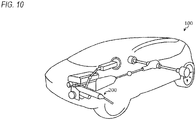
- a vehicle 100 is equipped with an electric power steering apparatus 200 to which the above-described ball screw device is applied.
- the present application is based on Japanese Patent Application No. 2016-204621 filed on October 18, 2016 , the contents of which are incorporated herein by reference.
Landscapes
- Engineering & Computer Science (AREA)
- Mechanical Engineering (AREA)
- General Engineering & Computer Science (AREA)
- Manufacturing & Machinery (AREA)
- Transmission Devices (AREA)
- Finish Polishing, Edge Sharpening, And Grinding By Specific Grinding Devices (AREA)
- Rolling Contact Bearings (AREA)
Applications Claiming Priority (2)
| Application Number | Priority Date | Filing Date | Title |
|---|---|---|---|
| JP2016204621 | 2016-10-18 | ||
| PCT/JP2017/035415 WO2018074186A1 (ja) | 2016-10-18 | 2017-09-29 | 軌道溝の加工方法、軸受、ボールねじ装置、機械及び車両の製造方法 |
Publications (2)
| Publication Number | Publication Date |
|---|---|
| EP3530407A1 true EP3530407A1 (de) | 2019-08-28 |
| EP3530407A4 EP3530407A4 (de) | 2019-10-16 |
Family
ID=62018514
Family Applications (1)
| Application Number | Title | Priority Date | Filing Date |
|---|---|---|---|
| EP17861832.8A Withdrawn EP3530407A4 (de) | 2016-10-18 | 2017-09-29 | Laufbahnrillenbearbeitungsverfahren, lager, kugelgewindevorrichtung, maschine und fahrzeugherstellungsverfahren |
Country Status (6)
| Country | Link |
|---|---|
| US (1) | US10464151B2 (de) |
| EP (1) | EP3530407A4 (de) |
| JP (2) | JP6365796B1 (de) |
| CN (1) | CN109803790A (de) |
| TW (1) | TW201816307A (de) |
| WO (1) | WO2018074186A1 (de) |
Families Citing this family (3)
| Publication number | Priority date | Publication date | Assignee | Title |
|---|---|---|---|---|
| CN109625756B (zh) * | 2018-12-28 | 2024-02-13 | 宁波甬新东方电气有限公司 | 一种变压器移送装置 |
| CN111664234B (zh) * | 2020-04-29 | 2021-08-06 | 山东大学 | 一种双支承圆锥滚子丝杠螺母副及其制作方法 |
| CN114453829A (zh) * | 2021-06-30 | 2022-05-10 | 江西应用科技学院 | 一种多轴线及轴线可变零构件的快速成形方法及装置 |
Family Cites Families (16)
| Publication number | Priority date | Publication date | Assignee | Title |
|---|---|---|---|---|
| US3579911A (en) * | 1968-06-05 | 1971-05-25 | Floyd Steinmetz | Ball bearing lapping machine |
| US3696483A (en) * | 1971-01-21 | 1972-10-10 | Textron Inc | Method and apparatus for finishing an antifriction-bearing raceway |
| JPS5294855A (en) * | 1976-02-05 | 1977-08-09 | Kouji Yoshioka | Tool for varnishing round pipes |
| US5492030A (en) * | 1994-01-26 | 1996-02-20 | Thomson Saginaw Ball Screw Company, Inc. | Methods of making ball nuts for preloaded ball nut and screw assemblies |
| JPH09280255A (ja) * | 1996-04-08 | 1997-10-28 | Sanyo Special Steel Co Ltd | 軌道底に平坦部を設けたベアリング外輪素形品及び内輪素形品、それらの製造方法並びに使用するマンドレル及びロール |
| JP4230020B2 (ja) * | 1998-09-11 | 2009-02-25 | Thk株式会社 | ボールねじナット、該ボールねじナットを使用した直線案内装置及びステアリング用ボールねじ並びにボールねじナットの製造方法 |
| JP2000312943A (ja) * | 1999-04-28 | 2000-11-14 | Ricoh Co Ltd | 円筒面を有する被加工物の製造方法及びその製造装置、並びに流体軸受の動圧溝の製造方法及びその製造装置 |
| JP4514853B2 (ja) * | 1999-07-26 | 2010-07-28 | ティーアールダブリュ オートモーティブ ジャパン株式会社 | 中空ボールネジの製造方法及び該方法で製造された中空ボールネジを装備したステアリング装置 |
| CN1256211C (zh) * | 2001-09-29 | 2006-05-17 | 张国梁 | 制造滚珠丝杠副新方法 |
| JP4284951B2 (ja) * | 2002-09-11 | 2009-06-24 | 株式会社ジェイテクト | 玉軸受用軌道輪の製造方法 |
| JP2004100667A (ja) * | 2002-09-13 | 2004-04-02 | Toyota Motor Corp | 複数のバルブを備える内燃機関の運転制御 |
| JP2004204911A (ja) | 2002-12-24 | 2004-07-22 | Nsk Ltd | コマ式ボールねじ |
| JP2004223656A (ja) * | 2003-01-23 | 2004-08-12 | Nsk Ltd | ボールねじ装置、該装置のナットのねじ溝加工方法、該加工方法に用いるタップ及び該タップの加工方法 |
| JP2005083549A (ja) * | 2003-09-11 | 2005-03-31 | Ntn Corp | ボールねじナットおよびその製造方法 |
| CN102278440B (zh) * | 2010-06-08 | 2014-03-05 | 朱豪东 | 一种具有深沟轨道的滚珠螺帽及其制造方法 |
| RU2452608C1 (ru) * | 2010-11-17 | 2012-06-10 | Государственное образовательное учреждение высшего профессионального образования "Орловский государственный технический университет" (ОрелГТУ) | Способ раскатывания отверстий с непрерывным качением шариков |
-
2017
- 2017-09-29 JP JP2017566883A patent/JP6365796B1/ja active Active
- 2017-09-29 EP EP17861832.8A patent/EP3530407A4/de not_active Withdrawn
- 2017-09-29 US US16/081,291 patent/US10464151B2/en active Active
- 2017-09-29 TW TW106133584A patent/TW201816307A/zh unknown
- 2017-09-29 CN CN201780063076.0A patent/CN109803790A/zh not_active Withdrawn
- 2017-09-29 WO PCT/JP2017/035415 patent/WO2018074186A1/ja active Application Filing
-
2018
- 2018-06-21 JP JP2018117514A patent/JP2018164975A/ja active Pending
Also Published As
| Publication number | Publication date |
|---|---|
| JPWO2018074186A1 (ja) | 2018-10-18 |
| EP3530407A4 (de) | 2019-10-16 |
| US10464151B2 (en) | 2019-11-05 |
| US20190015916A1 (en) | 2019-01-17 |
| TW201816307A (zh) | 2018-05-01 |
| JP2018164975A (ja) | 2018-10-25 |
| WO2018074186A1 (ja) | 2018-04-26 |
| CN109803790A (zh) | 2019-05-24 |
| JP6365796B1 (ja) | 2018-08-01 |
Similar Documents
| Publication | Publication Date | Title |
|---|---|---|
| KR100568400B1 (ko) | 볼나사 너트, 그 볼나사 너트를 사용한 직선 안내장치 및 스티어링용 볼나사 및 볼나사 너트의 제조방법 | |
| US8950283B2 (en) | Method for manufacturing nut for ball screw and ball screw | |
| US10464151B2 (en) | Raceway groove machining method, bearing, ball screw device, machine and vehicle production method | |
| JP6408819B2 (ja) | 中空ラックバーの製造方法 | |
| JP2011255834A (ja) | ラック軸とその製造方法及びラックピニオン式ステアリングギヤユニット | |
| CA2275559A1 (en) | Method for forming a workpiece by flow-forming | |
| JP2019076905A (ja) | ラックバーブランク材、ラックバー、ラックバーブランク材の製造方法及びラックバーの製造方法 | |
| JP2006181638A (ja) | ラジアル玉軸受用軌道輪及びその製造方法 | |
| JP4888760B2 (ja) | ねじ軸形成方法及びボールねじ機構のねじ軸 | |
| JP7179991B2 (ja) | 被加工物上のボール軌道、および、そのようにして製造されたボール軌道を有するボールねじナットの製造方法 | |
| JP5998511B2 (ja) | ボールねじの製造方法 | |
| JP2007278414A (ja) | スラストころ軸受用保持器とその製造方法 | |
| KR100525265B1 (ko) | 차동장치의 피니언샤프트 제조방법과 피니언샤프트 치수교정용 금형 | |
| JP4162070B2 (ja) | ボールネジの製造装置及び製造方法 | |
| JP2008215422A (ja) | アクチュエータ用ボールねじおよびそのねじ溝加工方法 | |
| JP2002283195A (ja) | ボールねじ軸の製造方法 | |
| CN115734830A (zh) | 轴承元件的制造方法、轴承的制造方法、机械的制造方法、车辆的制造方法、轴承元件、轴承、机械、以及车辆 | |
| JP2007253198A (ja) | 転造工具及びウォームとウォームに併存するスプラインとの同時転造方法 | |
| JP2022188334A (ja) | 転造盤及びこの転造盤を用いたウォームの製造方法とウォーム | |
| JP2023116041A (ja) | ボールねじ用ナットおよびボールねじ装置 | |
| JP2010075962A (ja) | ウォーム転造装置およびウォーム転造方法 | |
| JP2005299706A (ja) | ウォーム及びこれの製造方法 | |
| JP2016132001A (ja) | 転造加工方法 |
Legal Events
| Date | Code | Title | Description |
|---|---|---|---|
| PUAI | Public reference made under article 153(3) epc to a published international application that has entered the european phase |
Free format text: ORIGINAL CODE: 0009012 |
|
| 17P | Request for examination filed |
Effective date: 20190211 |
|
| AK | Designated contracting states |
Kind code of ref document: A1 Designated state(s): AL AT BE BG CH CY CZ DE DK EE ES FI FR GB GR HR HU IE IS IT LI LT LU LV MC MK MT NL NO PL PT RO RS SE SI SK SM TR |
|
| AX | Request for extension of the european patent |
Extension state: BA ME |
|
| A4 | Supplementary search report drawn up and despatched |
Effective date: 20190917 |
|
| RIC1 | Information provided on ipc code assigned before grant |
Ipc: B23G 1/22 20060101ALI20190911BHEP Ipc: B23P 15/00 20060101ALI20190911BHEP Ipc: F16H 25/24 20060101ALI20190911BHEP Ipc: B24B 19/06 20060101ALI20190911BHEP Ipc: B24B 39/02 20060101AFI20190911BHEP |
|
| DAV | Request for validation of the european patent (deleted) | ||
| DAX | Request for extension of the european patent (deleted) | ||
| STAA | Information on the status of an ep patent application or granted ep patent |
Free format text: STATUS: THE APPLICATION HAS BEEN WITHDRAWN |
|
| 18W | Application withdrawn |
Effective date: 20200825 |