EP3530225A1 - Plaque osseuse mandibulaire - Google Patents
Plaque osseuse mandibulaire Download PDFInfo
- Publication number
- EP3530225A1 EP3530225A1 EP19166823.5A EP19166823A EP3530225A1 EP 3530225 A1 EP3530225 A1 EP 3530225A1 EP 19166823 A EP19166823 A EP 19166823A EP 3530225 A1 EP3530225 A1 EP 3530225A1
- Authority
- EP
- European Patent Office
- Prior art keywords
- bone
- facing surface
- mandible
- bone plate
- mandibular
- Prior art date
- Legal status (The legal status is an assumption and is not a legal conclusion. Google has not performed a legal analysis and makes no representation as to the accuracy of the status listed.)
- Withdrawn
Links
Images


Classifications
-
- A—HUMAN NECESSITIES
- A61—MEDICAL OR VETERINARY SCIENCE; HYGIENE
- A61B—DIAGNOSIS; SURGERY; IDENTIFICATION
- A61B17/00—Surgical instruments, devices or methods, e.g. tourniquets
- A61B17/56—Surgical instruments or methods for treatment of bones or joints; Devices specially adapted therefor
- A61B17/58—Surgical instruments or methods for treatment of bones or joints; Devices specially adapted therefor for osteosynthesis, e.g. bone plates, screws, setting implements or the like
- A61B17/68—Internal fixation devices, including fasteners and spinal fixators, even if a part thereof projects from the skin
- A61B17/80—Cortical plates, i.e. bone plates; Instruments for holding or positioning cortical plates, or for compressing bones attached to cortical plates
- A61B17/8085—Cortical plates, i.e. bone plates; Instruments for holding or positioning cortical plates, or for compressing bones attached to cortical plates with pliable or malleable elements or having a mesh-like structure, e.g. small strips
-
- A—HUMAN NECESSITIES
- A61—MEDICAL OR VETERINARY SCIENCE; HYGIENE
- A61B—DIAGNOSIS; SURGERY; IDENTIFICATION
- A61B17/00—Surgical instruments, devices or methods, e.g. tourniquets
- A61B17/16—Bone cutting, breaking or removal means other than saws, e.g. Osteoclasts; Drills or chisels for bones; Trepans
- A61B17/17—Guides or aligning means for drills, mills, pins or wires
- A61B17/1728—Guides or aligning means for drills, mills, pins or wires for holes for bone plates or plate screws
-
- A—HUMAN NECESSITIES
- A61—MEDICAL OR VETERINARY SCIENCE; HYGIENE
- A61B—DIAGNOSIS; SURGERY; IDENTIFICATION
- A61B17/00—Surgical instruments, devices or methods, e.g. tourniquets
- A61B17/16—Bone cutting, breaking or removal means other than saws, e.g. Osteoclasts; Drills or chisels for bones; Trepans
- A61B17/17—Guides or aligning means for drills, mills, pins or wires
- A61B17/1739—Guides or aligning means for drills, mills, pins or wires specially adapted for particular parts of the body
- A61B17/176—Guides or aligning means for drills, mills, pins or wires specially adapted for particular parts of the body for the jaw
-
- A—HUMAN NECESSITIES
- A61—MEDICAL OR VETERINARY SCIENCE; HYGIENE
- A61B—DIAGNOSIS; SURGERY; IDENTIFICATION
- A61B17/00—Surgical instruments, devices or methods, e.g. tourniquets
- A61B17/56—Surgical instruments or methods for treatment of bones or joints; Devices specially adapted therefor
- A61B17/58—Surgical instruments or methods for treatment of bones or joints; Devices specially adapted therefor for osteosynthesis, e.g. bone plates, screws, setting implements or the like
- A61B17/68—Internal fixation devices, including fasteners and spinal fixators, even if a part thereof projects from the skin
- A61B17/80—Cortical plates, i.e. bone plates; Instruments for holding or positioning cortical plates, or for compressing bones attached to cortical plates
- A61B17/8004—Cortical plates, i.e. bone plates; Instruments for holding or positioning cortical plates, or for compressing bones attached to cortical plates with means for distracting or compressing the bone or bones
- A61B17/8014—Cortical plates, i.e. bone plates; Instruments for holding or positioning cortical plates, or for compressing bones attached to cortical plates with means for distracting or compressing the bone or bones the extension or compression force being caused by interaction of the plate hole and the screws
-
- A—HUMAN NECESSITIES
- A61—MEDICAL OR VETERINARY SCIENCE; HYGIENE
- A61B—DIAGNOSIS; SURGERY; IDENTIFICATION
- A61B17/00—Surgical instruments, devices or methods, e.g. tourniquets
- A61B17/56—Surgical instruments or methods for treatment of bones or joints; Devices specially adapted therefor
- A61B17/58—Surgical instruments or methods for treatment of bones or joints; Devices specially adapted therefor for osteosynthesis, e.g. bone plates, screws, setting implements or the like
- A61B17/68—Internal fixation devices, including fasteners and spinal fixators, even if a part thereof projects from the skin
- A61B17/80—Cortical plates, i.e. bone plates; Instruments for holding or positioning cortical plates, or for compressing bones attached to cortical plates
- A61B17/8061—Cortical plates, i.e. bone plates; Instruments for holding or positioning cortical plates, or for compressing bones attached to cortical plates specially adapted for particular bones
- A61B17/8071—Cortical plates, i.e. bone plates; Instruments for holding or positioning cortical plates, or for compressing bones attached to cortical plates specially adapted for particular bones for the jaw
-
- A—HUMAN NECESSITIES
- A61—MEDICAL OR VETERINARY SCIENCE; HYGIENE
- A61B—DIAGNOSIS; SURGERY; IDENTIFICATION
- A61B17/00—Surgical instruments, devices or methods, e.g. tourniquets
- A61B17/56—Surgical instruments or methods for treatment of bones or joints; Devices specially adapted therefor
- A61B17/58—Surgical instruments or methods for treatment of bones or joints; Devices specially adapted therefor for osteosynthesis, e.g. bone plates, screws, setting implements or the like
- A61B17/68—Internal fixation devices, including fasteners and spinal fixators, even if a part thereof projects from the skin
- A61B17/84—Fasteners therefor or fasteners being internal fixation devices
- A61B17/86—Pins or screws or threaded wires; nuts therefor
- A61B17/8685—Pins or screws or threaded wires; nuts therefor comprising multiple separate parts
-
- A—HUMAN NECESSITIES
- A61—MEDICAL OR VETERINARY SCIENCE; HYGIENE
- A61B—DIAGNOSIS; SURGERY; IDENTIFICATION
- A61B17/00—Surgical instruments, devices or methods, e.g. tourniquets
- A61B17/56—Surgical instruments or methods for treatment of bones or joints; Devices specially adapted therefor
- A61B17/58—Surgical instruments or methods for treatment of bones or joints; Devices specially adapted therefor for osteosynthesis, e.g. bone plates, screws, setting implements or the like
- A61B17/68—Internal fixation devices, including fasteners and spinal fixators, even if a part thereof projects from the skin
- A61B17/84—Fasteners therefor or fasteners being internal fixation devices
- A61B17/86—Pins or screws or threaded wires; nuts therefor
- A61B17/8605—Heads, i.e. proximal ends projecting from bone
-
- A—HUMAN NECESSITIES
- A61—MEDICAL OR VETERINARY SCIENCE; HYGIENE
- A61B—DIAGNOSIS; SURGERY; IDENTIFICATION
- A61B90/00—Instruments, implements or accessories specially adapted for surgery or diagnosis and not covered by any of the groups A61B1/00 - A61B50/00, e.g. for luxation treatment or for protecting wound edges
- A61B90/03—Automatic limiting or abutting means, e.g. for safety
- A61B2090/037—Automatic limiting or abutting means, e.g. for safety with a frangible part, e.g. by reduced diameter
-
- A—HUMAN NECESSITIES
- A61—MEDICAL OR VETERINARY SCIENCE; HYGIENE
- A61F—FILTERS IMPLANTABLE INTO BLOOD VESSELS; PROSTHESES; DEVICES PROVIDING PATENCY TO, OR PREVENTING COLLAPSING OF, TUBULAR STRUCTURES OF THE BODY, e.g. STENTS; ORTHOPAEDIC, NURSING OR CONTRACEPTIVE DEVICES; FOMENTATION; TREATMENT OR PROTECTION OF EYES OR EARS; BANDAGES, DRESSINGS OR ABSORBENT PADS; FIRST-AID KITS
- A61F2/00—Filters implantable into blood vessels; Prostheses, i.e. artificial substitutes or replacements for parts of the body; Appliances for connecting them with the body; Devices providing patency to, or preventing collapsing of, tubular structures of the body, e.g. stents
- A61F2/02—Prostheses implantable into the body
- A61F2/28—Bones
- A61F2/2803—Bones for mandibular reconstruction
Definitions
- An individual may require a mandible reconstruction due to trauma, atrophy, or a tumor.
- the surgeon may cut the mandible on either side of the tumor thereby separating the tumor from the mandible. Once the tumor is removed, the mandible is separated into a first part and a second part. If needed, the first part and/or the second part may be repositioned and screws and plates are used to fix the first part and the second part together until natural bone healing takes place.
- the mandibular bone plates currently used are shaped so as to be attached to a buccal surface, and in some cases on an inferior surface of the mandible. As a result, these plates have relatively high profiles which may cause irritation to the surrounding soft tissue such as for example to the surrounding blood vessels, muscles, nerves, and skin, and may also cause palpable cosmetic deformities. Furthermore, the adaptation of these plates to facilitate an anatomical placement may result in degraded performance and/or reduced fatigue life.
- a mandibular bone plate that is configured to be attached to a mandible that defines a buccal surface, a lingual surface, and an inferior surface that joins the buccal surface to the lingual surface, can include a curved chin portion having a first end and a second end and a first extension portion that extends from the first end along a first axis and is elongate along the first axis so as to define a proximal end that is proximate the first end and a distal end that is spaced from the proximal end along the first axis.
- the first extension portion can define a first bone facing surface, a first outer surface that is opposite the first bone facing surface, and a plurality of bone anchor holes that extend from the first bone facing surface to the first outer surface.
- the first bone facing surface can have an inferior end and a superior end that is spaced from the inferior end along a first direction that is perpendicular to the first axis.
- the first extension portion can be oriented such that a line that is tangential to the inferior end and to the superior end of the first bone facing surface along the first direction at a distal portion of the first extension portion is rotated about the first axis relative to a line that is tangential to the inferior end and to the superior end of the first bone facing surface along the first direction at a proximal portion of the first extension portion so that the first bone facing surface is configured to abut at least a portion of at least two of the buccal, lingual and inferior surfaces of the mandible when the mandibular bone plate is attached to the mandible.
- a mandibular bone plate can include a body that defines a bone facing surface, an outer surface that is opposite the bone facing surface, and a plurality of bone anchor holes that extend through the body from the bone facing surface to the outer surface.
- the body can include a chin portion and first and second extension portions that extend from the chin portion such that the bone facing surface of the chin portion faces the inferior surface of the mandible when the mandibular bone plate is attached to the mandible and the bone facing surfaces of the first and second extension portions at least partially face the lingual surface of the mandible when the mandibular bone plate is attached to the mandible.
- a method of affixing a bone plate to a mandible having a buccal surface, a lingual surface, and an inferior surface that extends from the lingual surface to the buccal surface can include the steps of exposing the inferior and lingual surfaces of the mandible; positioning a bone plate against the mandible such that portions of the bone plate abut the lingual surface of the mandible; and affixing the bone plate to the mandible with a plurality of bone anchors.
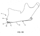
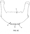
- a mandibular bone plate 10 can be configured to be affixed to a mandible 14 to thereby correct certain conditions of the mandible related to structure, growth, Temporomandibular Joint Disorder (TMJ disorder) or to correct orthodontic problems.
- the mandible 14 defines an outer or buccal surface 18, an inner or lingual surface 22, and a lower or inferior surface 26 that extends from the lingual surface 22 to the buccal surface 18.
- the mandibular bone plate 10 is configured to be affixed to the mandible 14 such that portions of the mandibular bone plate 10 abut the lingual surface 22 of the mandible 14.
- the mandibular bone plate 10 can be further configured to be affixed to the mandible 14 such that portions of the mandibular bone plate 10 also face the inferior surface 26 of the mandible 14 to thereby avoid certain tissue such as for example a throat portion 15. It should be appreciated, however, that the mandibular bone plate 10 can be configured to be positioned to abut both the buccal and inferior surfaces 18 and 26 or all three surfaces 18, 22, and 26 of the mandible 14 as desired. Because of the positioning and geometry of the mandibular bone plate 10, at least the palpability of the bone plate 10 can be reduced, as compared to bone plates that are attached solely to the buccal or inferior surfaces 18 and 26 of the mandible 14.
- mandible 14 is for illustration purposes only and that the mandibular bone plate 10 can be attached to any type of mandible in any type of condition.
- the mandibular bone plate 10 can be configured to be attached to an atrophic mandible.
- the mandibular bone plate 10 can be configured to be affixed to the mandible 14 for any desired reason and/or to correct/treat any type of condition, fracture, or reconstruction.
- the terms “lateral,” “longitudinal,” and “transverse” are used to describe the orthogonal directional components of various components.
- the transverse direction T extends vertically generally along the superior-inferior (or cranial-caudal) direction, while the plane defined by the longitudinal direction L and lateral direction A extends horizontally, generally in the anatomical plane defined by the medial-lateral direction and the anterior-posterior direction.
- the directional terms "vertical” and “horizontal” are used to describe the mandibular bone plate 10 and its components as illustrated merely for the purposes of clarity and illustration.
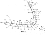
- the mandibular bone plate 10 can include a substantially v-shaped body 40 that defines a proximal end P and a distal end D.
- the v-shaped body can further define a bone facing surface 44, an outer surface 48 that is opposite the bone facing surface 44 at least partially along the transverse direction T, and a plurality of bone anchor holes 52 that extend through the body 40 from the bone facing surface 44 to the outer surface 48.
- the mandibular bone plate 10, and in particular, the v-shaped body 40 can include a chin portion 56, a first extension portion 60 that extends from the chin portion 56 generally along the lateral direction A, and a second extension portion 64 that extends from the chin portion 56 generally along the lateral direction A.
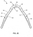
- the chin portion 56, first extension portion 60, and the second extension portion 64 are oriented such that the bone facing surface 44 of the chin portion 56 faces the inferior surface 26 of the mandible 14 when the mandibular bone plate 10 is attached to the mandible 14 and the bone facing surfaces 44 of the first and second extension portions 60 and 64 at least partially face the lingual surface 22 of the mandible 14 when the mandibular bone plate 10 is attached to the mandible 14. It should be appreciated, however, that the chin portion 56, the first extension portion 60, and the second extension portion 64 can be oriented such that the bone plate 10 abuts or otherwise faces at least two of the buccal, lingual, and inferior surfaces 18, 22, and 26. It should further be appreciated, that the body 40 can have any general shape as desired.
- the body 40 could be substantially U-shaped as desired, or substantially J-shaped as desired. Therefore it should further be appreciated, that the bone plate 10 can be configured as one J-shaped plate or as a pair of J-shaped plates each having a chin portion and a respective extension.
- the orientation of the bone facing surface 44 can be anatomically derived.
- the orientation of the bone facing surface 44 can be derived by taking statistics of a plurality of mandibles 14 to thereby derive an orientation that would correspond to a majority of mandibles. It should be appreciated, however, that the orientation of the bone facing surface 44 can be derived using any method as desired.
- the mandibular bone plate 10 can be formed from a variety of biocompatible materials, such as cobalt chromium molybdenum (CoCrMo), titanium, and titanium alloys, stainless steel, ceramics, or polymers such as polyetheretherketone (PEEK), polyetherketoneketone (PEKK), bioresorbable and/composite materials.
- a coating may be added or applied to the mandibular bone plate 10 to improve physical or chemical properties or to provide medications. Examples of coatings include plasma-sprayed titanium, Hydroxyapatite, or antibacterial coatings.
- the chin portion 56 can be curved along the longitudinal direction L and has a first end 72a and a second end 72b that is spaced from the first end 72a along the longitudinal direction L. As shown in Figs. 2A-2F , the chin portion 56 can define a chin bone facing surface 76 of the bone facing surface 44, an outer surface 80 that is opposite the chin bone facing surface 76, and at least one bone anchor hole 84 of the bone anchor holes 52, such as a plurality of bone anchor holes 84, that extend through the chin portion 56 from the chin bone facing surface 76 to the outer surface 80. As shown in Fig.
- the chin portion 56 can be flat such that the chin bone facing surface 76 faces and is spaced from the inferior surface 26 of the mandible 14 when the mandibular bone plate 10 is attached to the mandible 14. It should be appreciated, however, that the chin portion 56 can have any configuration as desired.
- the chin portion 56 can include undulations or otherwise be configured such that at least a portion of the chin bone facing surface 76 faces the lingual surface 22 of the mandible 14 when the mandibular bone plate 10 is attached to the mandible 14 and/or such that at least a portion of the chin bone facing surface 76 abuts the inferior surface 26 of the mandible 14.
- the chin portion 56 can further define a first side surface 88 that extends from the outer surface 80 to the chin bone facing surface 76 and a second side surface 92 that is opposite the first side surface 88 and extends from the outer surface 80 to the chin bone facing surface 76.
- the first and second side surfaces 88 and 92 can be convex or otherwise curved.
- the chin portion 56 can further include a plurality of weakened portions 96 between adjacent bone anchor holes 84. The weakened portions 96 are configured to allow the chin portion 56 to be bent during implantation of the mandibular bone plate 10.
- each weakened portion 96 is defined by at least a first recess 100 that extends into the first side surface 88 and a second recess 102 that extends into the second side surface 92 opposite the first recess 100.
- the chin portion 56 includes six bone anchor holes 84 and four weakened portions 96. It should be appreciated, however, that the chin portion 56 can include any number of bone anchor holes 84 as desired and any number of weakened portions 96 as desired. It should be further appreciated, that the weakened portions 96 can be defined by other structure. For example, the weakened portions 96 can be defined by recesses formed in the chin bone facing surface 76 and/or the outer surface 80.
- the first and second recesses 100 and 102 can also be configured as suture retention recesses.
- a suture that is used to approximate tissue that is overlying the mandible can be wrapped around the chin portion 56 within the first and second recesses 100 and 102.
- the first and second recesses 100 and 102 can help prevent migration of the suture after approximation. It should be appreciated, that the suture can be wrapped around the chin portion 56 such that the suture is looped around the chin portion once or such that the suture is wrapped around the chin portion 56 multiple times, as desired.
- the chin portion 56 up to the entirety of the chin portion 56 can be substantially triangular shaped in cross-section. That is, the chin portion 56 can taper from the first side surface 88 to the second side surface 92. Therefore a thickness of the chin portion 56 at the second side surface 92 can be less than that of the chin portion 56 at a center of the chin portion 56 between the first and second side surfaces 88 and 92. It should be appreciated, however, that the chin portion 56 can have any shape in cross-section as desired. For example, the chin portion 56 can be rectangular shaped in cross-section as desired.
- substantially triangular shaped means to have either a triangular shape or the general appearance of a triangle.
- the chin portion 56 has first and second side surfaces 88 and 92, because of the taper, the chin portion 56 substantially defines a triangle in cross-section.
- the first extension portion 60 generally extends from the first end 72a along a first axis A 1 and is elongate along the first axis A 1
- the second extension portion 64 generally extends from the second end 72b along a second axis A 2 and is elongate along the second axis A 2
- the first extension portion 60 defines a proximal end 73a that is proximate the first end 72a and a distal end 73b that is spaced from the proximal end 73a along the first axis A 1 .
- the second extension portion 64 defines a proximal end 74a that is proximate the second end 72b and a distal end 74b that is spaced from the proximal end 74a along the first axis A 2 .
- the first extension portion 60 defines a first bone facing surface 106 of the bone facing surface 44, a first outer surface 110 that is opposite the first bone facing surface 106, and a plurality of bone anchor holes 114 of the plurality of bone anchor holes 52 that extend from the first bone facing surface 106 to the first outer surface 110.
- the second extension portion 64 defines a second bone facing surface 118 of the bone facing surface 44, a second outer surface 122 that is opposite the first bone facing surface 118, and a plurality of bone anchor holes 128 of the plurality of bone anchor holes 52 that extend from the second bone facing surface 118 to the second outer surface 122.
- the chin bone facing surface 76, the first bone facing surface 106, and the second bone facing surface 118 are coincident so as to define the bone facing surface 44 of the body 40 such that the bone facing surface 44 is continuous.
- the outer surfaces 80, 110, and 122 are coincident so as to define the outer surface 48 of the body 40 such that the outer surface 48 is continuous.
- the surfaces 76, 106, and 118 and/or the surfaces 80, 110, and 122 can be interrupted so as to provide minimal or reduced contact with the bone.
- any of the surfaces 76, 80, 106, 110, 118, and 122 can define a scallop or recess that interrupts the continuity of the surfaces.
- the first bone facing surface 106 defines an inferior end 106a and a superior end 106b that is spaced from the inferior end 106a along a first direction that is perpendicular to the first axis A 1 .
- the second bone facing surface 118 defines an inferior end 118a and a superior end 118b that is spaced from the inferior end 106a along a second direction that is perpendicular to the second axis A 2 .
- the first and second directions should be taken along the shortest distance between the respective inferior and superior ends. It should be appreciated, that the first and second directions will change along the length of the first and second extension portions 60 and 64 because the orientation of the first and second extension portions 60 and 64 changes along their lengths. That is the first and second directions will be a direction that takes the shortest path from the inferior end to the superior end that is perpendicular to the respective axes at any point along the first and second extension portions 60 and 64.
- the first and second extension portions 60 and 64 are generally spaced from each other along the longitudinal direction L and the first and second axes A 1 and A 2 are angularly offset from each other such that an angle ⁇ is defined between the first and second axes A 1 and A 2 . Therefore, the first and second extension portions 60 and 64 diverge as they extend distally from the chin portion 56. It should be appreciated that the angle ⁇ can be any angle as desired.
- the first extension portion 60 is twisted counterclockwise about the first axis A 1 relative to the curved chin portion 56 such that the first bone facing surface 106 is configured to abut at least a portion of the lingual surface 22 of the mandible 14 when the mandibular bone plate 10 is attached to the mandible 14. That is, the first extension portion 60 is rotated counterclockwise about the first axis A 1 relative to the chin portion 56 from the proximal end 73a and toward the distal end 73b so as to define a twisted shape such that portions of the first bone facing surface 106 face laterally outward relative to the chin bone facing surface and away from the second bone facing surface 118.
- the first bone facing surface 106 can face away from the second bone facing surface 118 such that a line that is normal to the first bone facing surface 106 has at least a directional component that extends away from the second bone facing surface 118 along the longitudinal direction L.
- the first extension portion 60 is oriented such that a line N 1 that is normal to the first bone facing surface 106 at a distal portion of the first extension portion 60 is rotated about the first axis A 1 relative to a line N 2 that is normal to the first bone facing surface 106 at a proximal portion of the first extension portion 106 so that the first bone facing surface 60 is configured to abut at least a portion of at least two of the buccal, lingual and inferior surfaces of the mandible when the mandibular bone plate 10 is attached to the mandible.
- the first extension portion 60 is oriented such that a line M 1 that is tangential to the inferior end 106a and to the superior end 106b of the first bone facing surface 106 along the first direction at a distal portion of the first extension portion 60 is rotated about the first axis A 1 relative to a line M 2 that is tangential to the inferior end 106a and to the superior end 106b of the first bone facing surface along the first direction at a proximal portion of the first extension portion 106 so that the first bone facing surface 60 is configured to abut at least a portion of at least two of the buccal, lingual and inferior surfaces of the mandible when the mandibular bone plate 10 is attached to the mandible.
- the proximal portion can be at the proximal end 73a or some portion between the proximal end 73a and distal end 73b, and the distal portion can be any portion between the proximal end 73a and the distal end 73b that is distal to the proximal portion.
- the first extension portion 60 can be twisted along a portion of a length of the first extension portion 60 and up to the entire length of the first extension portion 60. It should also be appreciated, that twisted is used to describe the orientation of the first extension portion 60 and does not necessarily mean that the first extension portion 60 was actually twisted to form the disclosed orientation.
- the first extension portion 60 can be molded or milled to define the twisted orientation.
- the first bone facing surface 106 includes a plurality of non-linear undulations 140 that correspond to respective surface portions of the mandible 14 such as the lingual surface 22 when the mandibular bone plate 10 is attached to the mandible 14. It should be appreciated, that the first extension portion 60 can be twisted counterclockwise or otherwise rotated about the first axis A 1 such that the first bone facing surface 106 is configured to also abut at least a portion of the inferior surface 26 of the mandible 14 or any two of the when the mandibular bone plate 10 is attached to the mandible 14.
- the first extension portion 60 can further define a third side surface 150 that extends from the first outer surface 110 to the first bone facing surface 106 and a fourth side surface 154 that is opposite the third side surface 150 and extends from the first outer surface 110 to the first bone facing surface 106.
- the third and fourth side surfaces 106 and 110 can be convex or otherwise curved.
- the first extension portion 60 can further include a plurality of weakened portions 158 between adjacent bone anchor holes 114. The weakened portions 158 are configured to allow the first extension portion 60 to be bent during implantation of the mandibular bone plate 10 and/or to be shortened.
- the weakened portions 158 are proximate to the distal end D of the first extension portion 60 such that the first extension portion 60 can be cut or otherwise broken at one of the weakened portions 158 to thereby shorten the first extension portion 60.
- Each weakened portion 158 is defined by at least a first recess 162 that extends into the third side surface 150 and a second recess 166 that extends into the fourth side surface 154 opposite the first recess 162.
- the first extension portion 60 includes nine bone anchor holes 114 and three weakened portions 158. It should be appreciated, however, that the first extension portion 60 can include any number of bone anchor holes 114 as desired and any number of weakened portions 158 as desired. It should be further appreciated, that the weakened portions 158 can be defined by other structure.
- the weakened portions 158 can be defined by recesses formed in the first bone facing surface 106 and/or the outer surface 110.
- the first extension portion 60 up to an entirety of the first extension portion 60 can be substantially triangular shaped in cross-section. That is, the first extension portion 60 can taper from the third side surface 150 to the fourth side surface 154. Therefore a thickness of the first extension portion 60 at the fourth side surface 154 can be less than that of the first extension portion 60 at a center of the first extension portion 60 between the third and fourth side surfaces 150 and 154. It should be appreciated, however, that the first extension portion 60 can have any shape in cross-section, as desired. For example, the first extension portion 60 can be rectangular shaped in cross-section as desired.
- the first bone facing surface 106 can be convex from the third side surface 150 to the fourth side surface 154.
- the convex shape can help conform the mandibular bone plate 10 to at least one of the surfaces 18, 22, and 26 of the mandible 14. It should be appreciated, however, that the first bone facing surface 106 can have any shape as desired.
- the first bone facing surface 106 can be substantially flat as desired.
- the second extension portion 64 is twisted clockwise about the second axis A 2 relative to the curved chin portion 56 such that the second bone facing surface 118 is configured to abut at least a portion of the lingual surface 22 of the mandible 14 when the mandibular bone plate 10 is attached to the mandible 14. That is, the second extension portion 64 is rotated clockwise about the second axis A 2 relative to the chin portion 56 from the proximal end 74a and toward the distal end 74b so as to define a twisted shape such that portions of the second bone facing surface 118 face laterally outward relative to the chin bone facing surface 76 and away from the first bone facing surface 106.
- the second bone facing surface 118 can face away from the first bone facing surface 106 such that a line that is normal to the second bone facing surface 118 has at least a directional component that extends away from the first bone facing surface 106 along the longitudinal direction L.
- the second extension portion 64 is oriented such that a line N 3 that is normal to the first bone facing surface 118 at a distal portion of the second extension portion 64 is rotated about the second axis A 2 relative to a line N 4 that is normal to the second bone facing surface 118 at a proximal portion of the second extension portion 64 so that the second bone facing surface 118 is configured to abut at least a portion of at least two of the buccal, lingual and inferior surfaces of the mandible when the mandibular bone plate 10 is attached to the mandible.
- the second extension portion 64 is oriented such that a line M 3 that is tangential to the inferior end 118a and to the superior end 118b along the second direction at a distal portion of the second extension portion 64 is rotated about the second axis A 2 relative to a line M 4 that is tangential to the inferior end 118a and to the superior end 118b along the second direction at a proximal portion of the second extension portion 64 so that the second bone facing surface 118 is configured to abut at least a portion of at least two of the buccal, lingual and inferior surfaces of the mandible when the mandibular bone plate 10 is attached to the mandible.
- the proximal portion can be at the proximal end or some portion between the proximal end 74a and distal end 74b, and the distal portion can be any portion between the proximal end 74a and the distal end 74b that is distal to the proximal portion.
- the second extension portion 64 can be twisted along a portion of a length of the second extension portion 64 and up to the entire length of the second extension portion 64. It should also be appreciated, that twisted is used to describe the orientation of the second extension portion 64 and does not necessarily mean that the second extension portion 64 was actually twisted to form the disclosed orientation.
- the second extension portion 64 can be molded or milled to define the twisted orientation.
- the second bone facing surface 118 also includes a plurality of non-linear undulations 140 that correspond to respective surface portions of the mandible 14 such as the lingual surface 22 when the mandibular bone plate 10 is attached to the mandible 14. It should be appreciated, that second extension portion 64 can be twisted clockwise about the second axis A 2 such that the second bone facing surface 118 is configured to also abut at least a portion of the inferior surface 26 of the mandible 14 when the mandibular bone plate 10 is attached to the mandible 14.
- the second extension portion 64 can further define a fifth side surface 180 that extends from the second outer surface 122 to the second bone facing surface 118 and a sixth side surface 184 that is opposite the fifth side surface 180 and extends from the second outer surface 122 to the second bone facing surface 118.
- the fifth and sixth side surfaces 118 and 122 can be convex or otherwise curved.
- the second extension portion 64 can further include a plurality of weakened portions 188 between adjacent bone anchor holes 128. The weakened portions 188 are configured to allow the second extension portion 64 to be bent during implantation of the mandibular bone plate 10 and/or to be shortened.
- the weakened portions 158 are proximate to the distal end D of the second extension portion 64 such that the second extension portion 64 can be cut or otherwise broken at one of the weakened portions 188 to thereby shorten the second extension portion 64.
- Each weakened portion 188 is defined by at least a first recess 192 that extends into the fifth side surface 180 and a second recess 196 that extends into the sixth side surface 184 opposite the first recess 192.
- the second extension portion 64 includes nine bone anchor holes 128 and three weakened portions 188. It should be appreciated, however, that the second extension portion 64 can include any number of bone anchor holes 128 as desired and any number of weakened portions 188 as desired. It should be further appreciated, that the weakened portions 188 can be defined by other structure. For example, the weakened portions 188 can be defined by recesses formed in the second bone facing surface 118 and/or the outer surface 122.
- the second extension portion 64 up to an entirety of the second extension portion 64 can be substantially triangular shaped in cross-section. That is the second extension portion 64 can taper from the fifth side surface 180 to the sixth side surface 184. Therefore a thickness of the second extension portion 64 at the sixth side surface 184 can be less than that of a center of the second extension portion 64 between the fifth and sixth side surfaces 180 and 184. It should be appreciated, however, that the second extension portion 64 can have any shape in cross-section. For example, the second extension portion 64 can be rectangular shaped in cross-section as desired. It should be further appreciated, that substantially triangular shaped means to have the general appearance of a triangle.
- the second bone facing surface 118 can be convex from the fifth side surface 180 to the sixth side surface 184.
- the convex shape can help conform the mandibular bone plate 10 to one of the surfaces 18, 22, and 26 of the mandible 14.
- the second bone facing surface 118 can have any shape as desired.
- the second bone facing surface 118 can be substantially flat as desired.
- the bone anchor holes 52 such as the bone anchor holes 84 of the chin portion 56, the bone anchor holes 114 of the first extension portion 60, and the bone anchor holes 128 of the second extension portion 64 can be configured as locking or compression holes and as fixed axis or variable angle holes.
- each bone anchor hole 114 and 128 of the first and second extension portions 60 and 64 defines a respective central axis A H , and at least some of the central axes A H are angular offset with respect to the other central axes A H . Therefore, the bone anchors that are received within the holes 114 and 128 will have different trajectories as they pass through the holes 114 and 128.
- the bone anchor holes 52 can all or in part have central axes A H that are parallel or that converge on one or more points that define a trajectory origin or destination.
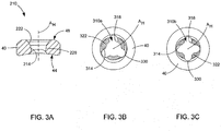
- variable angle compression hole 210 can be defined by an interior surface 214 of the bone plate body 40.
- An upper portion of the interior surface 214 can be tapered radially inward toward the central axis A H from the bone facing surface 44 toward the outer surface 48 and a lower portion of the interior surface 214 can converge away from the central axis A H .
- the interior surface 214 can be unthreaded and configured to engage an unthreaded head of a compression bone anchor or screw that provides a compressive force against the bone plate 10 in a direction toward the mandible 14. As shown in Fig.
- an outer region 222 of the upper portion of the interior surface 214 can be curved such that a diameter of the hole 210 decreases variably along the central axis A H
- an interior region 228 of the upper portion of the interior surface 214 can be linear such that the diameter of the hole 210 decreases linearly along the central axis A H .
- each variable angle hole 310a and 310b is defined by an interior surface 314 of the bone plate body 40.
- the interior surface 314 includes a plurality of columns 318 that extend between the bone facing surface 44 and the outer surface 48.
- three columns 318 can be equidistantly spaced circumferentially about the hole 310a and in accordance with the embodiment illustrated in Fig.
- each column 318 presents internal threads 322 that face the respective holes 310a and 310b such that, if the columns 318 were expanded to join each other (i.e. if extended completely around the interior surface 314), the columns 318 would form a continuous helical thread that extends about the central axis A H of the respective holes 310a and 310b.
- the threads 322 of adjacent columns 318 are operatively aligned with each other.
- the columns 318 present internal helical threads 322 as illustrated, the columns 318 alternatively can define threads that are provided as teeth formed thereon.
- the columns of teeth if expanded to join each other (i.e., if extended completely around the interior surface 314), will not form a helical thread, but a series of concentric ridges and grooves perpendicular to the central axis A H of the bone anchor hole 52.
- the teeth can be operatively aligned with each other.
- the columns 318 are circumferentially spaced from each other so as to define corresponding axes that are angled with respect to the transverse central axis A H , such that a screw can extend through the holes 310a and 310b at any of a variety of angled axes while threadedly fixed to the threads 322.
- the interior surfaces 314 that define the holes 310a and 310b each further includes a plurality of arcuate pockets 330 that project into the plate body 40 at a location circumferentially between the adjacent columns 318.
- the pockets 330 each presents an arcuate surface 334 that is concave with respect to a direction radially outward from the central axis A H of the respective hole 310a and 310b.
- the variable angle holes 310a and 310b can be configured to allow the bone anchor or screw to engage the threads 318 at any angular orientation as desired, up to +/- 15° (e.g., within a 30 ° range) with respect to the central axis A H .
- the bone plate 10 is illustrated as including variable angle holes 210, 310a, and 310b extending through the bone plate body 40, the bone plate 10 can alternatively include any type of bone anchor hole 52 as desired.
- all of or some of the bone anchor holes 52 can be configured as fixed axis holes.
- a bone anchor such as a screw 410 can be used to affix or otherwise attach the mandibular bone plate 10 to the mandible 14.
- the screw 410 can include a shaft 414 and a head 418 that extends from the shaft 414.
- the shaft 414 can carry a thread 422 that is configured to engage bone to thereby attach the bone plate 10 to the mandible 14.
- the head 418 can also carry a thread 426 that is configured to engage the threads 322 of the holes 310a or 310b to thereby lock the bone screw 410 to the bone plate 10.
- the screw 410 can be configured as a variable angle screw so that the screw 410 can be inserted through the holes 310a and 310b at a variety of angles.
- the screw 410 can be configured as a fix angle screw as desired. It should further be appreciated, that the screw 410 can be configured as a compression screw.
- the screw 410 can include a head 418 that is void of threads 426 such that the head 418 defines a surface that abuts against the outer region 222 of the bone anchor hole 210 when the screw 410 is passed through one of the holes 210 and into the mandible 14.
- the mandibular bone plate 10 can be affixed or otherwise attached to the mandible 14 with any type of bone anchor or screw as desired. For example, pins, rivets, k-wires, etc.
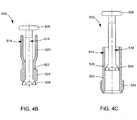
- a bone anchor such as an expandable fixation member 510 can be used to affix or otherwise attach the mandibular bone plate 10 to the mandible 14.
- the expandable fixation member 510 can include a cannulated or annular shaft 514 and an expansion member 518 that extends through the cannulated shaft 514.
- the shaft 514 can include a body 520 that define an expandable region 522 at its distal end.
- the shaft 514 can further include a shoulder 524 that extends radially out from the body 520 at the expandable region 522.
- the expansion member 518 can include a head 526 at a proximal end and a mandrel 528 at a distal end.
- the mandrel 528 will enter the cannulation of the shaft 514 to thereby cause the expandable region 522 to expand radially outward as shown in Fig. 4C .
- the expanded expandable region 522 places the shoulder 524 further radially outward.
- the expandable fixation member 510 can have a variety of configurations.
- the expandable fixation member 510 can have any of the configurations disclosed in United States Publication No 2011/0046682 , assigned to Synthes USA, LLC, the contents of which are hereby incorporated by reference in their entirety herein.
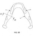
- the mandibular bone plate 10 can be attached to the mandible 14 such that portions of the bone plate 10 face the inferior surface 26 of the mandible and portions of the bone plate 10 face the lingual surface 22 of the mandible 14.
- the inferior 26 and lingual 22 surfaces of the mandible 14 can be exposed and the bone plate 10 can be positioned against the mandible such that portions of the bone plate 10 abut the lingual surface 22 of the mandible 14.
- the bone plate 10 can then be attached to the mandible 14 with a plurality of bone anchors such as screws 410. In this way the mandibular bone plate 10 can be positioned against the mandible 14 from a submandibular surgical approach. It should be appreciated, however, that the mandibular bone plate 10 can be positioned from any desired approach.
- the mandibular bone plate 10 can be positioned such that portions of the bone plate 10 abut the lingual surface 22 and at least one portion of the bone plate 10 faces the inferior surface 26 of the mandible 14.
- the chin portion 56 can face the inferior surface 26 such that the chin bone facing surface 76 is spaced from the inferior surface 26 by a distance d 1 . It should be appreciated, however, that the chin bone facing surface 76 can abut the inferior surface 26 as desired.
- the first and second bone facing surfaces 106 and 118 can abut both the lingual surface 22 and the inferior surface 26.
- the bone plate 10 is positioned such that the extension portions 60 and 64 taper as they extend from the lingual surface 22 and toward the buccal surface 18. Because of the positioning of the first and second extension portions 60 and 64 and because of the taper of the first and second extension portions 60 and 64, the palpability of the mandibular bone plate 10 can be reduced.
- mandibular bone plate 10 can be configured so as to abut the buccal and inferior surfaces 18 and 26 or can be configured to abut all three surfaces 18, 22, and 26 such that the taper of the extension portions 60 and 64 achieves the reduced palpability.
- the bone plate 10 Prior to or during the positioning of the bone plate 10, the bone plate 10 can be shortened by cutting the first and second extension portions 60 and 64 at the weakened portions 158 and 188. Further prior to or during the positioning of the bone plate 10, the bone plate 10 can be bent or otherwise manipulated at any of the weakened portions 96, 158, and 188 of the chin portion 56, first extension portion 60, and second extension portion 64 to thereby better conform the bone plate 10 to the mandible 14.
- a drill guide 610 can be used to form holes 614 in the mandible 14.
- the drill guide 610 can be configured as a bi-directional drill guide that is capable of aligning a drill bit such that the holes 614 can be drilled into the buccal surface 18 of the mandible 14 and toward either the lingual surface 22 or the inferior surface 26 or such that holes 614 can be drilled into the lingual or inferior surfaces 22 and 26 and toward the buccal surface 18.
- the drill guide 610 can include a C-shaped body 616 having a first end 618 and a second end 622 spaced from the first end along a first direction.
- the drill guide 610 can further include a first guide portion 630 coupled to the first end 618 and a second guide portion 634 coupled to the second end 622.
- the first and second guide portions 630 and 634 can each define a respective guide path 638 that extends through the first and second guide portions 630 and 634 along the first direction such that the guide paths 638 of the first and second guide portions 630 and 634 are aligned along the first direction.
- the drill guide 610 can be positioned such that the first guide portion 630 is aligned with a bone anchor hole 52 of the mandibular bone plate 10 and the second guide portion 634 is aligned with the buccal surface 18 of the mandible 14.
- a drill bit can then be moved through either the guide path 638 of the first guide portion 630 or through the guide path 638 of the second guide portion 634 to thereby form a hole 614 in the mandible 14.
- the drill bit can have a first trajectory TR 1 through the first guide portion 630 and a second trajectory TR 2 through the second guide portion 634 that is opposite the first trajectory TR 1 .
- the guide paths 638 are oriented so that when the drill guide 610 is positioned adjacent the bone plate 10 and the mandible 14 a drill bit boring into the mandible 14 will avoid nerves or other soft tissue.
- the mandibular bone plate 10 can be attached to the mandible 14 by inserting a bone anchor such as a screw 410 through the buccal surface 18 and into one of the bone anchor holes 52 of the bone plate 10.
- a bone anchor such as a screw 410
- the bone plate 10 can be attached to the mandible 14 from a variety of trajectories including from the lingual surface toward the buccal surface or inferior surface, the buccal surface toward the lingual surface or the inferior surface, and the inferior surface toward the lingual surface or buccal surface.
- the bone anchor holes 52 of the mandibular bone plate 10 can be configured to provide an interstitially spaced hole pattern.
- a first bone anchor hole such as hole 52a can be positioned such that a bone anchor received within the first bone anchor hole extends into the inferior surface 26 of the mandible and a second bone anchor hole such as hole 52b can be positioned such that a bone anchor received within the second bone anchor hole extends into the lingual surface 22.
- the holes 52 can be positioned such that the bone anchors have any trajectory as desired and extend into any surface of the mandible as desired.
- suture can be used to attach soft tissue to the bone plate 10.
- the soft tissue can be attached to the bone plate by wrapping a suture around the chin portion 56 within the first and second recesses 100 and 102. It should be appreciated, however, that the soft tissue can be attached to the bone plate in other ways.
- the suture can be threaded through one of the bone anchor holes 84 as desired.
- the mandibular bone plate 10 along with at least one such as a plurality of bone anchors, and/or the drill guide 610 can be provided as a kit. Therefore, the bone plate 10, along with any of the bone anchors 410 and/or 510, and/or the drill guide 610 can be provided as a kit. It should be appreciated, however, that the bone plate 10 or drill guide 610 can be provided as a kit with any desired components.
Applications Claiming Priority (4)
| Application Number | Priority Date | Filing Date | Title |
|---|---|---|---|
| US201361783482P | 2013-03-14 | 2013-03-14 | |
| US13/827,184 US9572610B2 (en) | 2013-03-14 | 2013-03-14 | Mandibular bone plate |
| EP14713646.9A EP2994064B1 (fr) | 2013-03-14 | 2014-03-03 | Plaque osseuse mandibulaire |
| PCT/US2014/019774 WO2014158740A1 (fr) | 2013-03-14 | 2014-03-03 | Plaque osseuse mandibulaire |
Related Parent Applications (2)
| Application Number | Title | Priority Date | Filing Date |
|---|---|---|---|
| EP14713646.9A Division EP2994064B1 (fr) | 2013-03-14 | 2014-03-03 | Plaque osseuse mandibulaire |
| EP14713646.9A Division-Into EP2994064B1 (fr) | 2013-03-14 | 2014-03-03 | Plaque osseuse mandibulaire |
Publications (1)
| Publication Number | Publication Date |
|---|---|
| EP3530225A1 true EP3530225A1 (fr) | 2019-08-28 |
Family
ID=50390204
Family Applications (2)
| Application Number | Title | Priority Date | Filing Date |
|---|---|---|---|
| EP19166823.5A Withdrawn EP3530225A1 (fr) | 2013-03-14 | 2014-03-03 | Plaque osseuse mandibulaire |
| EP14713646.9A Active EP2994064B1 (fr) | 2013-03-14 | 2014-03-03 | Plaque osseuse mandibulaire |
Family Applications After (1)
| Application Number | Title | Priority Date | Filing Date |
|---|---|---|---|
| EP14713646.9A Active EP2994064B1 (fr) | 2013-03-14 | 2014-03-03 | Plaque osseuse mandibulaire |
Country Status (7)
| Country | Link |
|---|---|
| EP (2) | EP3530225A1 (fr) |
| JP (1) | JP6502313B2 (fr) |
| KR (1) | KR20150127261A (fr) |
| CN (1) | CN105073044B (fr) |
| BR (1) | BR112015022735A2 (fr) |
| CA (1) | CA2905770A1 (fr) |
| WO (1) | WO2014158740A1 (fr) |
Families Citing this family (4)
| Publication number | Priority date | Publication date | Assignee | Title |
|---|---|---|---|---|
| CN105520776A (zh) * | 2016-01-20 | 2016-04-27 | 上海景堂医疗器械有限公司 | 四段式下颌骨成型板 |
| JP2019533564A (ja) * | 2016-10-25 | 2019-11-21 | デピュイ・シンセス・プロダクツ・インコーポレイテッド | 骨プレート用縫合糸接続システム |
| JP7201166B2 (ja) * | 2018-12-05 | 2023-01-10 | Jsr株式会社 | 外科手術用デバイス、情報処理装置、システム、情報処理方法、およびプログラム |
| RU208411U1 (ru) * | 2021-06-22 | 2021-12-16 | Федеральное государственное бюджетное образовательное учреждение высшего образования "Кемеровский государственный медицинский университет" Министерства здравоохранения Российской Федерации | Индивидуальный хирургический шаблон для проведения остеосинтеза при переломах угла и тела нижней челюсти |
Citations (6)
| Publication number | Priority date | Publication date | Assignee | Title |
|---|---|---|---|---|
| US5087259A (en) * | 1989-12-22 | 1992-02-11 | Christian Krenkel | Orthopedic plate to fix in position portions of bone when reconstructing the lower jaw |
| US6423068B1 (en) * | 2000-10-18 | 2002-07-23 | Erhard Reisberg | Method and apparatus for mandibular osteosynthesis |
| US6730091B1 (en) * | 1999-05-03 | 2004-05-04 | Medartis Ag | Blockable bone plate |
| DE102005032026B3 (de) * | 2005-07-08 | 2006-12-14 | Stryker Leibinger Gmbh & Co. Kg | Osteosyntheseplatte mit schräg zur Plattenebene verlaufenden Durchgangsöffnungen |
| US20100131013A1 (en) * | 2008-11-24 | 2010-05-27 | Ralph James D | Clavicle plate and screws |
| US20110046682A1 (en) | 2009-07-06 | 2011-02-24 | Synthes Gmbh Or Synthes Usa, Llc | Expandable fixation assemblies |
Family Cites Families (8)
| Publication number | Priority date | Publication date | Assignee | Title |
|---|---|---|---|---|
| JPH01178255A (ja) * | 1988-01-09 | 1989-07-14 | Ohara:Kk | 歯槽骨インプラント、下顎骨インプラント並びにそれらを組み合わせてなる下顎骨再建インプラント |
| US5380328A (en) * | 1993-08-09 | 1995-01-10 | Timesh, Inc. | Composite perforated implant structures |
| US5769637A (en) * | 1996-05-22 | 1998-06-23 | Sofamor Danek Properties, Inc. | Dental implant and alveolar process augmentation structures and method of installation |
| JP2006230803A (ja) * | 2005-02-25 | 2006-09-07 | Eugene Sherry | 置換骨組織 |
| WO2006099766A1 (fr) * | 2005-03-24 | 2006-09-28 | Medartis Ag | Plaque d'osteosynthese |
| CN2902227Y (zh) * | 2006-04-07 | 2007-05-23 | 昆山市蓝博创伟医疗器械有限公司 | 颌面人工关节 |
| WO2012118843A1 (fr) * | 2011-02-28 | 2012-09-07 | Tissue Regeneration Systems, Inc. | Échafaudages modulaires pour tissus |
| CN202060847U (zh) * | 2011-04-15 | 2011-12-07 | 沈军 | 下颌骨重建定位器 |
-
2014
- 2014-03-03 BR BR112015022735A patent/BR112015022735A2/pt not_active IP Right Cessation
- 2014-03-03 EP EP19166823.5A patent/EP3530225A1/fr not_active Withdrawn
- 2014-03-03 JP JP2016500534A patent/JP6502313B2/ja not_active Expired - Fee Related
- 2014-03-03 EP EP14713646.9A patent/EP2994064B1/fr active Active
- 2014-03-03 CA CA2905770A patent/CA2905770A1/fr not_active Abandoned
- 2014-03-03 CN CN201480015446.XA patent/CN105073044B/zh not_active Expired - Fee Related
- 2014-03-03 KR KR1020157028891A patent/KR20150127261A/ko not_active Application Discontinuation
- 2014-03-03 WO PCT/US2014/019774 patent/WO2014158740A1/fr active Application Filing
Patent Citations (6)
| Publication number | Priority date | Publication date | Assignee | Title |
|---|---|---|---|---|
| US5087259A (en) * | 1989-12-22 | 1992-02-11 | Christian Krenkel | Orthopedic plate to fix in position portions of bone when reconstructing the lower jaw |
| US6730091B1 (en) * | 1999-05-03 | 2004-05-04 | Medartis Ag | Blockable bone plate |
| US6423068B1 (en) * | 2000-10-18 | 2002-07-23 | Erhard Reisberg | Method and apparatus for mandibular osteosynthesis |
| DE102005032026B3 (de) * | 2005-07-08 | 2006-12-14 | Stryker Leibinger Gmbh & Co. Kg | Osteosyntheseplatte mit schräg zur Plattenebene verlaufenden Durchgangsöffnungen |
| US20100131013A1 (en) * | 2008-11-24 | 2010-05-27 | Ralph James D | Clavicle plate and screws |
| US20110046682A1 (en) | 2009-07-06 | 2011-02-24 | Synthes Gmbh Or Synthes Usa, Llc | Expandable fixation assemblies |
Also Published As
| Publication number | Publication date |
|---|---|
| CN105073044B (zh) | 2017-11-17 |
| EP2994064A1 (fr) | 2016-03-16 |
| CA2905770A1 (fr) | 2014-10-02 |
| CN105073044A (zh) | 2015-11-18 |
| JP2016511061A (ja) | 2016-04-14 |
| KR20150127261A (ko) | 2015-11-16 |
| JP6502313B2 (ja) | 2019-04-17 |
| EP2994064B1 (fr) | 2019-05-08 |
| WO2014158740A1 (fr) | 2014-10-02 |
| BR112015022735A2 (pt) | 2017-07-18 |
Similar Documents
| Publication | Publication Date | Title |
|---|---|---|
| JP6404397B2 (ja) | 大腿骨頸部骨折用インプラント | |
| BR112015003749B1 (pt) | Sistema de fixação óssea | |
| US10028779B2 (en) | Mandibular bone plate | |
| EP2994064B1 (fr) | Plaque osseuse mandibulaire | |
| US10085779B2 (en) | Intramedullary device for mid-shaft clavicle fractures | |
| US11337818B2 (en) | Systems and methods for fusion of anatomical joints | |
| US11123120B2 (en) | Implants, alignment guides, systems and methods of use | |
| CN216221619U (zh) | 一种胫骨远端前侧锁定板 | |
| CN211325504U (zh) | 一种胫骨近端外侧异形块 | |
| CN105105837B (zh) | 接骨钢板系统 |
Legal Events
| Date | Code | Title | Description |
|---|---|---|---|
| PUAI | Public reference made under article 153(3) epc to a published international application that has entered the european phase |
Free format text: ORIGINAL CODE: 0009012 |
|
| AC | Divisional application: reference to earlier application |
Ref document number: 2994064 Country of ref document: EP Kind code of ref document: P |
|
| AK | Designated contracting states |
Kind code of ref document: A1 Designated state(s): AL AT BE BG CH CY CZ DE DK EE ES FI FR GB GR HR HU IE IS IT LI LT LU LV MC MK MT NL NO PL PT RO RS SE SI SK SM TR |
|
| RIN1 | Information on inventor provided before grant (corrected) |
Inventor name: CORNELIUS, CARL-PETER |
|
| RIN1 | Information on inventor provided before grant (corrected) |
Inventor name: CORNELIUS, CARL-PETER |
|
| STAA | Information on the status of an ep patent application or granted ep patent |
Free format text: STATUS: REQUEST FOR EXAMINATION WAS MADE |
|
| 17P | Request for examination filed |
Effective date: 20200228 |
|
| RBV | Designated contracting states (corrected) |
Designated state(s): AL AT BE BG CH CY CZ DE DK EE ES FI FR GB GR HR HU IE IS IT LI LT LU LV MC MK MT NL NO PL PT RO RS SE SI SK SM TR |
|
| 18W | Application withdrawn |
Effective date: 20210225 |