EP3529152B1 - Überkopf-gepäckfach für ein flugzeug - Google Patents
Überkopf-gepäckfach für ein flugzeug Download PDFInfo
- Publication number
- EP3529152B1 EP3529152B1 EP16784899.3A EP16784899A EP3529152B1 EP 3529152 B1 EP3529152 B1 EP 3529152B1 EP 16784899 A EP16784899 A EP 16784899A EP 3529152 B1 EP3529152 B1 EP 3529152B1
- Authority
- EP
- European Patent Office
- Prior art keywords
- luggage compartment
- spring
- damping
- damping element
- overhead
- Prior art date
- Legal status (The legal status is an assumption and is not a legal conclusion. Google has not performed a legal analysis and makes no representation as to the accuracy of the status listed.)
- Active
Links
Images



Classifications
-
- B—PERFORMING OPERATIONS; TRANSPORTING
- B64—AIRCRAFT; AVIATION; COSMONAUTICS
- B64D—EQUIPMENT FOR FITTING IN OR TO AIRCRAFT; FLIGHT SUITS; PARACHUTES; ARRANGEMENT OR MOUNTING OF POWER PLANTS OR PROPULSION TRANSMISSIONS IN AIRCRAFT
- B64D11/00—Passenger or crew accommodation; Flight-deck installations not otherwise provided for
- B64D11/003—Stowage devices for passengers' personal luggage
-
- E—FIXED CONSTRUCTIONS
- E05—LOCKS; KEYS; WINDOW OR DOOR FITTINGS; SAFES
- E05F—DEVICES FOR MOVING WINGS INTO OPEN OR CLOSED POSITION; CHECKS FOR WINGS; WING FITTINGS NOT OTHERWISE PROVIDED FOR, CONCERNED WITH THE FUNCTIONING OF THE WING
- E05F1/00—Closers or openers for wings, not otherwise provided for in this subclass
- E05F1/08—Closers or openers for wings, not otherwise provided for in this subclass spring-actuated, e.g. for horizontally sliding wings
- E05F1/10—Closers or openers for wings, not otherwise provided for in this subclass spring-actuated, e.g. for horizontally sliding wings for swinging wings, e.g. counterbalance
- E05F1/1041—Closers or openers for wings, not otherwise provided for in this subclass spring-actuated, e.g. for horizontally sliding wings for swinging wings, e.g. counterbalance with a coil spring perpendicular to the pivot axis
- E05F1/1066—Closers or openers for wings, not otherwise provided for in this subclass spring-actuated, e.g. for horizontally sliding wings for swinging wings, e.g. counterbalance with a coil spring perpendicular to the pivot axis with a traction spring
- E05F1/1075—Closers or openers for wings, not otherwise provided for in this subclass spring-actuated, e.g. for horizontally sliding wings for swinging wings, e.g. counterbalance with a coil spring perpendicular to the pivot axis with a traction spring for counterbalancing
-
- E—FIXED CONSTRUCTIONS
- E05—LOCKS; KEYS; WINDOW OR DOOR FITTINGS; SAFES
- E05F—DEVICES FOR MOVING WINGS INTO OPEN OR CLOSED POSITION; CHECKS FOR WINGS; WING FITTINGS NOT OTHERWISE PROVIDED FOR, CONCERNED WITH THE FUNCTIONING OF THE WING
- E05F1/00—Closers or openers for wings, not otherwise provided for in this subclass
- E05F1/08—Closers or openers for wings, not otherwise provided for in this subclass spring-actuated, e.g. for horizontally sliding wings
- E05F1/10—Closers or openers for wings, not otherwise provided for in this subclass spring-actuated, e.g. for horizontally sliding wings for swinging wings, e.g. counterbalance
- E05F1/1091—Closers or openers for wings, not otherwise provided for in this subclass spring-actuated, e.g. for horizontally sliding wings for swinging wings, e.g. counterbalance with a gas spring
-
- E—FIXED CONSTRUCTIONS
- E05—LOCKS; KEYS; WINDOW OR DOOR FITTINGS; SAFES
- E05F—DEVICES FOR MOVING WINGS INTO OPEN OR CLOSED POSITION; CHECKS FOR WINGS; WING FITTINGS NOT OTHERWISE PROVIDED FOR, CONCERNED WITH THE FUNCTIONING OF THE WING
- E05F5/00—Braking devices, e.g. checks; Stops; Buffers
- E05F5/02—Braking devices, e.g. checks; Stops; Buffers specially for preventing the slamming of swinging wings during final closing movement, e.g. jamb stops
-
- E—FIXED CONSTRUCTIONS
- E05—LOCKS; KEYS; WINDOW OR DOOR FITTINGS; SAFES
- E05Y—INDEXING SCHEME ASSOCIATED WITH SUBCLASSES E05D AND E05F, RELATING TO CONSTRUCTION ELEMENTS, ELECTRIC CONTROL, POWER SUPPLY, POWER SIGNAL OR TRANSMISSION, USER INTERFACES, MOUNTING OR COUPLING, DETAILS, ACCESSORIES, AUXILIARY OPERATIONS NOT OTHERWISE PROVIDED FOR, APPLICATION THEREOF
- E05Y2201/00—Constructional elements; Accessories therefor
- E05Y2201/40—Motors; Magnets; Springs; Weights; Accessories therefor
- E05Y2201/47—Springs
- E05Y2201/488—Traction springs
-
- E—FIXED CONSTRUCTIONS
- E05—LOCKS; KEYS; WINDOW OR DOOR FITTINGS; SAFES
- E05Y—INDEXING SCHEME ASSOCIATED WITH SUBCLASSES E05D AND E05F, RELATING TO CONSTRUCTION ELEMENTS, ELECTRIC CONTROL, POWER SUPPLY, POWER SIGNAL OR TRANSMISSION, USER INTERFACES, MOUNTING OR COUPLING, DETAILS, ACCESSORIES, AUXILIARY OPERATIONS NOT OTHERWISE PROVIDED FOR, APPLICATION THEREOF
- E05Y2800/00—Details, accessories and auxiliary operations not otherwise provided for
- E05Y2800/20—Combinations of elements
- E05Y2800/21—Combinations of elements of identical elements, e.g. of identical compression springs
-
- E—FIXED CONSTRUCTIONS
- E05—LOCKS; KEYS; WINDOW OR DOOR FITTINGS; SAFES
- E05Y—INDEXING SCHEME ASSOCIATED WITH SUBCLASSES E05D AND E05F, RELATING TO CONSTRUCTION ELEMENTS, ELECTRIC CONTROL, POWER SUPPLY, POWER SIGNAL OR TRANSMISSION, USER INTERFACES, MOUNTING OR COUPLING, DETAILS, ACCESSORIES, AUXILIARY OPERATIONS NOT OTHERWISE PROVIDED FOR, APPLICATION THEREOF
- E05Y2900/00—Application of doors, windows, wings or fittings thereof
- E05Y2900/50—Application of doors, windows, wings or fittings thereof for vehicles
- E05Y2900/502—Application of doors, windows, wings or fittings thereof for vehicles for aircraft or spacecraft
-
- E—FIXED CONSTRUCTIONS
- E05—LOCKS; KEYS; WINDOW OR DOOR FITTINGS; SAFES
- E05Y—INDEXING SCHEME ASSOCIATED WITH SUBCLASSES E05D AND E05F, RELATING TO CONSTRUCTION ELEMENTS, ELECTRIC CONTROL, POWER SUPPLY, POWER SIGNAL OR TRANSMISSION, USER INTERFACES, MOUNTING OR COUPLING, DETAILS, ACCESSORIES, AUXILIARY OPERATIONS NOT OTHERWISE PROVIDED FOR, APPLICATION THEREOF
- E05Y2900/00—Application of doors, windows, wings or fittings thereof
- E05Y2900/50—Application of doors, windows, wings or fittings thereof for vehicles
- E05Y2900/53—Type of wing
- E05Y2900/538—Interior lids
Definitions
- the invention relates to an overhead luggage compartment for an aircraft, with an upper luggage compartment element, with a lower luggage compartment element which can be moved between an open and a closed position, and with a spring and damping device having a spring element and a damping element, which is connected to a side panel of the upper luggage compartment element and is connected to a side wall of the lower luggage compartment element.
- Such overhead luggage compartments are, for example, from AT 513 939 known.
- spring-damper units are arranged between the fixed part and the moving part of the overhead luggage compartment.
- the spring is built into the damper, so that the known spring-damper units have a comparatively large diameter.
- the disadvantage is that the available storage volume inside the luggage compartment is reduced. If such a spring-damper unit is arranged on both sides of each luggage compartment, the capacity is reduced accordingly.
- the spring force of the spring largely depends on its diameter. Accordingly, it is not readily possible to increase the storage volume of the luggage compartment by using a slimmer spring.
- More overhead bins are off WO 03/033346 A1 , US 2011/0253714 A1 , DE 43 35 151 A1 , DE 10 2014 012 125 A1 and DE 10 2011 110 750 A1 known.
- the object of the present invention is to alleviate or eliminate the disadvantages of the prior art.
- the invention therefore aims in particular to increase the storage volume of the overhead luggage compartment of the type mentioned at the outset, without impairing the support of the closing process by the spring and damping device.
- the spring element is outside of Damping element, offset in a direction parallel to the main plane of the side panel of the upper luggage compartment element or the side wall of the lower luggage compartment element to the damping element.
- the spring element of the spring and damping device according to the invention is arranged outside of the interior of the damping element, in particular next to the damping element.
- the longitudinal axis of the spring element is arranged at a distance from the longitudinal axis of the damping element in a direction parallel to the main plane of the side panel of the upper luggage compartment element or the side wall of the lower luggage compartment element.
- the spring element is in the direction parallel to the main or panel plane of the side panel of the upper luggage compartment element or in the direction parallel to the main or wall plane of the side wall of the lower luggage compartment element, i.e. essentially perpendicular to the direction of flight when the luggage compartment is installed in the aircraft , arranged offset relative to the damping element.
- the damping element it is therefore not necessary for the damping element to be dimensioned to accommodate the spring element.
- This design has the particular advantage that the extent of the spring and damping device can be reduced in the direction perpendicular to the main plane of the side wall of the upper luggage compartment element, ie in the longitudinal direction of the luggage compartment element or in the direction of flight. In this way, the storage volume of the luggage compartment element can be increased without impairing the spring force, which is dependent in particular on the diameter of the spring element, for supporting the movement of the lower luggage compartment element from the open to the closed position.
- the arrangement of the spring element next to the damping element, transversely to the direction of flight has no influence on the storage volume of the luggage compartment element, since sufficient installation space is available in this direction.
- the spring element is integrated into the damping element, resulting in a comparatively large diameter, which disadvantageously reduces the longitudinal extension between two side panels of the upper luggage compartment element and thus the storage volume for the luggage.
- the spring element is designed as a lifting spring, which is biased in the direction of the closed position of the lower luggage compartment element. Accordingly, the spring element is in a tensioned or expanded state when the lower luggage compartment element is in the open position, with the spring element being relaxed or compressed when it is transferred into the closed position.
- the spring element is arranged adjacent to the damping element.
- the spring element is located adjacent to but outside of and at a distance from the damping element.
- the diameter of the damping element can be reduced.
- essentially the same spring and damping characteristics can be achieved as with the dampers with built-in or integrated spring that are customary in the prior art.
- the longitudinal axis of the spring element In order to increase the volume available for luggage in the interior space between the upper and lower luggage compartment element, it is favorable for the longitudinal axis of the spring element to be essentially parallel to the longitudinal axis of the damping element, in the same plane parallel to the main plane of the side panel of the upper luggage compartment element or the Side wall of the lower luggage compartment element is arranged.
- the extension of the spring and damping device in the direction of flight can be minimized, as a result of which a maximum storage volume for pieces of luggage is achieved.
- the stress on the spring and damping device can be reduced in use.
- the spring and damping device has two spring elements, one spring element being arranged on one side of the damping element and the other spring element being arranged on the other side of the damping element.
- the damping element between two spring elements.
- the arrangement of the spring element outside of the damping element causes a moment on the damping element, which could cause damage to the damping element.
- the spring elements are preferably of essentially identical design.
- the spring elements are arranged essentially at the same distance from the damping element.
- the damping element is arranged essentially in the middle between the two spring elements, so that lateral forces on the damping element when the luggage compartment is opened or closed are reliably prevented.
- One end of the spring elements is connected to one another via a deflection roller. Since the spring forces are not exactly the same, the deflection roller between the spring elements serves to avoid a moment on the damping element. This reliably prevents the damping element from bending.
- the ends of the spring elements are preferably connected to one another via a flexible longitudinal element, in particular a piece of wire or cable, which is guided around the deflection roller.
- the flexible longitudinal element can have hooks at both ends, which are hooked into corresponding eyelets at the respective ends of the spring elements.
- one end of the damping element is articulated on the side wall of the lower luggage compartment element and the other end of the damping element is articulated on the side panel of the upper luggage compartment element.
- the side wall of the lower luggage compartment element is preferably connected to a bracket on which the pivot axis of one end of the damping element is arranged.
- a helical spring is provided as the spring element and/or an oil damper is provided as the damping element.
- the damping element preferably has a rebound stage and a compression stage, so that the damping element acts both during the opening process and during the closing process.
- the lower luggage compartment element is pivotably arranged on the upper luggage compartment element via a joint. This prevents the lower luggage compartment element from being pivoted between the open position, in which a loading opening for loading the luggage compartment with items of luggage is released, and a closed position, in which the loading opening is closed, by a direction running in the longitudinal direction of the luggage compartment, i.e. in the direction of flight, when it is opened - Allows or closing process substantially stationary pivot axis.
- the spring and damping device described above can also be used in other designs of overhead luggage compartments for aircraft.
- the spring and damping device can be provided in an overhead luggage compartment with a lowerable lower luggage compartment element, in which the lower luggage compartment element does not pivot about a stationary pivot axis, but rather from the upper closed position to the lower open position and vice versa is relocatable.
- an overhead luggage compartment 1 for aircraft is shown, which in the embodiment shown has two identically designed luggage compartment modules 1a, 1b.
- the luggage compartment modules 1a, 1b each have a stationary upper luggage compartment element 2 which can be fastened to a structural element, in particular to an aircraft fuselage (not shown).
- the luggage compartment 1 has a movable lower luggage compartment element 3.
- the luggage compartment 1 has a longitudinal extent, which is arranged in the direction of flight when installed.
- the movable luggage compartment element 3 is suspended on both sides via joints 4 with joint axes on the fixed luggage compartment element 2 .
- the joints 4 are located on overlapping sections of side walls 5 of the lower luggage compartment element 3 and side panels 6 of the upper luggage compartment element 2.
- the side walls 5 of the lower luggage compartment element 3 and the side panels 6 of the upper luggage compartment element 2 are each essentially flat or planar, with the Side walls 5 of the lower luggage compartment element 3 are arranged essentially parallel to the side panels 6 of the upper luggage compartment element 2 .
- the side walls 5 of the lower luggage compartment element 3 protrude laterally from a floor 5a, so that the lower luggage compartment element 3 is designed as a trough, half chute or U-shaped luggage compartment for accommodating luggage.
- the lower luggage compartment element 2 is between an open position (cf. the luggage compartment module 1a in 1 ), in which a loading opening 7 is released, and a closed position (cf. the luggage compartment module 1b in 1 ), in which the loading opening 7 is closed, pivotable.
- the lower luggage compartment element 3 has a handle element 8 on the visible side, with which the luggage compartment 1 can be opened or closed.
- off 1 schematically shows a spring and damping device 9 between the lower luggage compartment element 3 and the upper luggage compartment element 2, with which the pivoting of the movable luggage compartment element 3 from the open position to the closed position is supported and damping of the closing or opening process is achieved.
- a spring and damping device 9 is provided between each side wall 5 of the lower luggage compartment element 3 and each associated side panel 6 of the upper luggage compartment element 2 .
- the spring and damping device 9 has at least one spring element 10 to support the movement of the lower luggage compartment element 3 from the open to the closed position and a damping element 11 to dampen the movement of the lower luggage compartment element 3 . Both the opening and the closing of the luggage compartment 1 can preferably be damped by means of the damping element 11 .
- the damping element 11 has a cylinder 11a, in which a piston 11b can be displaced in the longitudinal direction, i.e. in the axial direction.
- a fluid in particular oil, is arranged in the cylinder 11a in a manner which is also known.
- the at least one spring element 10 is arranged outside of the damping element 11, with the spring element 10 extending next to the damping element 11.
- the longitudinal axis 12 of the spring element 10 is arranged offset to the longitudinal axis 14 of the damping element 11 in a direction 13 parallel to the main plane of the side panel 6 of the upper luggage compartment element 2, ie transversely to the direction of flight.
- the longitudinal axis 12 of the spring element 10 is arranged essentially parallel to the longitudinal axis 14 of the damping element 11, with the longitudinal axis 12 of the spring element 10 extending in the same vertical plane parallel to the main plane of the side panel 6 of the upper luggage compartment element 2.
- the spring and damping device 9 in the embodiment shown has exactly two spring elements 10, with one spring element 10 on one longitudinal side of the damping element 11 and the other spring element on the other longitudinal side of the damping element 11 is arranged.
- the spring elements 10 are arranged essentially parallel to one another, with the longitudinal axes 12 of the spring elements 10 extending essentially parallel and at the same distance from the damping element 11 .
- both spring elements 10 are designed as essentially identical helical springs, which are in a stretched state when the lower luggage compartment element 3 is in the open position, so that the movement of the lower luggage compartment element 3 from the open to the closed position is prevented by the action of the spring elements 10 is supported.
- the ends of the spring elements 10 are connected to one another via an elongate connecting element 15 for the purpose of compensating for forces or tolerances.
- the other ends of the spring elements 10 are each attached to a common bearing device 17, in particular a bearing plate, which is attached to the damping element 11.
- One end of the damping element 11 is pivotable about a pivot axis 18 on the side wall 5 of the lower luggage compartment element and the other end of the damping element 11 is pivotable about a pivot axis 19 on the side panel 6 of the upper luggage compartment element 2 .
- the pivot axis 18 of the damping element 11 is arranged on the side of the lower luggage compartment element 3 on a bracket projecting from the side wall 5 of the lower luggage compartment element 3 .
Landscapes
- Engineering & Computer Science (AREA)
- Aviation & Aerospace Engineering (AREA)
- Vibration Dampers (AREA)
- Vibration Prevention Devices (AREA)
- Vehicle Step Arrangements And Article Storage (AREA)
Description
- Die Erfindung betrifft ein Überkopf-Gepäckfach für ein Flugzeug, mit einem oberen Gepäckfachelement, mit einem unteren Gepäckfachelement, welches zwischen einer Offen- und einer Schließstellung beweglich ist, und mit einer ein Federelement und ein Dämpfungselement aufweisenden Feder- und Dämpfungseinrichtung, welche mit einem Seitenpaneel des oberen Gepäckfachelements und mit einer Seitenwand des unteren Gepäckfachelements verbunden ist.
- Derartige Überkopf-Gepäckfächer sind beispielsweise aus der
AT 513 939 - Weitere Überkopf-Gepäckfächer sind aus
WO 03/033346 A1 US 2011/0253714 A1 ,DE 43 35 151 A1 ,DE 10 2014 012 125 A1 undDE 10 2011 110 750 A1 bekannt. - Daneben ist aus
DE 20 2009 006 931 U1 ein Druckfluiddämpfer für Möbel bekannt, welcher zwei seitlich angeordnete Schraubenfedern aufweist. - Demnach besteht die Aufgabe der vorliegenden Erfindung darin, die Nachteile des Standes der Technik zu lindern bzw. zu beseitigen. Die Erfindung setzt sich daher insbesondere zum Ziel, das Aufnahmevolumen des Überkopf-Gepäckfachs der eingangs angeführten Art zu erhöhen, ohne die Unterstützung des Schließvorgangs durch die Feder- und Dämpfungseinrichtung zu beeinträchtigen.
- Erfindungsgemäß ist das Federelement außerhalb des Dämpfungselements, in eine Richtung parallel zur Hauptebene des Seitenpaneels des oberen Gepäckfachelements bzw. der Seitenwand des unteren Gepäckfachelements versetzt zu dem Dämpfungselement angeordnet.
- Demnach ist das Federelement der erfindungsgemäßen Feder- und Dämpfungseinrichtung außerhalb des Innenraums des Dämpfungselements, insbesondere neben dem Dämpfungselement, angeordnet. Die Längsachse des Federelements ist in eine Richtung parallel zur Hauptebene des Seitenpaneels des oberen Gepäckfachelements bzw. der Seitenwand des unteren Gepäckfachelements in einem Abstand zu der Längsachse des Dämpfungselements angeordnet. Demnach ist das Federelement in Richtung parallel zur Haupt- bzw. Paneelebene des Seitenpaneels des oberen Gepäckfachelements bzw. in Richtung parallel zur Haupt- bzw. Wandebene der Seitenwand des unteren Gepäckfachelements, d.h. bezogen auf den eingebauten Zustand des Gepäckfaches im Flugzeug im Wesentlichen senkrecht zur Flugrichtung, gegenüber dem Dämpfungselement versetzt angeordnet. Erfindungsgemäß ist es daher nicht erforderlich, dass das Dämpfungselement für die Aufnahme des Federelements dimensioniert werden muss. Diese Ausführung hat insbesondere den Vorteil, dass die Erstreckung der Feder- und Dämpfungseinrichtung in Richtung senkrecht zur Hauptebene der Seitenwand des oberen Gepäckfachelements, d.h. in Längsrichtung des Gepäckfachelements bzw. in Flugrichtung, reduziert werden kann. Auf diese Weise kann das Aufnahmevolumen des Gepäckfachelements vergrößert werden, ohne die insbesondere vom Durchmesser des Federelements abhängige Federkraft für die Unterstützung der Bewegung des unteren Gepäckfachelements von der Offen- in die Schließstellung zu beeinträchtigen. Die Anordnung des Federelements neben dem Dämpfungselement, quer zur Flugrichtung, hat hingegen keinen Einfluss auf das Aufnahmevolumen des Gepäckfachelements, da in diese Richtung ausreichender Einbauraum zur Verfügung steht. Vorteilhafterweise wird daher eine besonders flache Feder- und Dämpfungseinrichtung geschaffen. Demgegenüber ist das Federelement beim Stand der Technik in das Dämpfungselement integriert, woraus sich ein vergleichsweise großer Durchmesser ergibt, welcher nachteiligerweise die Längserstreckung zwischen zwei Seitenpaneelen des oberen Gepäckfachelements und damit das Aufnahmevolumen für die Gepäckstücke reduziert. Zur Unterstützung des Schließvorgangs ist das Federelement als Hebefeder ausgebildet, welche in Richtung der Schließstellung des unteren Gepäckfachelements vorgespannt ist. Demnach liegt das Federelement in der Offenstellung des unteren Gepäckfachelements in einem gespannten bzw. expandierten Zustand vor, wobei das Federelement bei der Überführung in die Schließstellung entspannt bzw. komprimiert wird.
- Um die kombinierte Feder- und Dämpfungswirkung beim Öffnungs- bzw. Schließvorgang zu erreichen, ist bevorzugt vorgesehen, dass das Federelement benachbart dem Dämpfungselement angeordnet ist. Bei dieser Ausführung ist das Federelement neben dem Dämpfungselement, jedoch außerhalb und in einem Abstand davon angeordnet. Dadurch kann einerseits der Durchmesser des Dämpfungselements reduziert werden. Andererseits kann im Wesentlichen dieselbe Feder- und Dämpfungscharakteristik wie bei den im Stand der Technik üblichen Dämpfern mit eingebauter bzw. integrierter Feder erzielt werden.
- Um das für Gepäckstücke zur Verfügung stehende Aufnahmevolumen im Innenraum zwischen dem oberen und unteren Gepäckfachelement zu vergrößern, ist es günstig, dass die Längsachse des Federelements im Wesentlichen parallel zur Längsachse des Dämpfungselements, in derselben Ebene parallel zur Hauptebene des Seitenpaneels des oberen Gepäckfachelements bzw. der Seitenwand des unteren Gepäckfachelements angeordnet ist. Dadurch wird eine flache Feder- und Dämpfungseinrichtung geschaffen, welche eine größere Erstreckung in Richtung der Hauptebene des Seitenpaneels des oberen Gepäckfachelements, d.h. quer zur Flugrichtung, als in Richtung senkrecht dazu, d.h. in Flugrichtung, aufweist. Auf diese Weise kann einerseits die Erstreckung der Feder- und Dämpfungseinrichtung in Flugrichtung minimiert werden, wodurch ein maximales Aufnahmevolumen für Gepäckstücke erzielt wird. Andererseits kann die Belastung der Feder- und Dämpfungseinrichtung in Gebrauch reduziert werden.
- Die Feder- und Dämpfungseinrichtung weist zwei Federelemente auf, wobei das eine Federelement auf der einen Seite des Dämpfungselements und das andere Federelement auf der anderen Seite des Dämpfungselements angeordnet ist. Bei dieser Ausführung ist das Dämpfungselement zwischen zwei Federelementen angeordnet. Durch die Anordnung von zwei Federelementen kann der die Federkraft bestimmende Durchmesser jedes Federelements gegenüber einer Ausführung mit einer einzigen Feder reduziert werden. Dadurch kann der für den Einbau der Feder- und Dämpfungseinrichtung in Flugrichtung notwendige Einbauraum verringert werden, wodurch das Aufnahmevolumen des Gepäckfaches bei gleichbleibender Federunterstützung für den Schließvorgang weiter erhöht werden kann. Darüber hinaus kann bei dieser Ausführung zuverlässig verhindert werden, dass die Anordnung des Federelements außerhalb des Dämpfungselements ein Moment auf das Dämpfungselement bewirkt, welches Schäden an dem Dämpfungselement hervorrufen könnte. Durch die Anordnung von zwei Federelementen beidseits des Dämpfungselements in Richtung senkrecht zur Flugrichtung kann vorteilhafterweise erreicht werden, dass das Dämpfungselement im Wesentlichen ausschließlich in dessen Wirkungs- bzw. Längsrichtung beansprucht wird. Somit kann die Funktion der Feder- und Dämpfungseinrichtung für lange Einsatzzeiten gewährleistet werden. Vorzugsweise sind die Federelemente im Wesentlichen ident ausgebildet.
- Zu diesem Zweck ist es überdies günstig, wenn die Federelemente im Wesentlichen in demselben Abstand zu dem Dämpfungselement angeordnet sind. Bei dieser Ausführung ist das Dämpfungselement im Wesentlichen mittig zwischen den beiden Federelementen angeordnet, so dass Querkräfte auf das Dämpfungselement beim Öffnen bzw. Schließen des Gepäckfaches zuverlässig verhindert werden.
- Die einen Enden der Federelemente sind über eine Umlenkrolle miteinander verbunden. Da die Federkräfte nicht exakt gleich sind, dient die Umlenkrolle zwischen den Federelementen zur Vermeidung eines Moments auf das Dämpfungselements. Somit wird ein Verbiegen des Dämpfungselements zuverlässig vermieden. Vorzugsweise sind die Enden der Federelemente über ein biegsames Längselement, insbesondere ein Draht- bzw. Seilstück, miteinander verbunden, welches um die Umlenkrolle geführt ist. Das biegsame Längselement kann an beiden Enden Haken aufweisen, welche in entsprechende Ösen an den jeweiligen Enden der Federelemente eingehängt sind.
- Zur Aufbringung der Federkraft beim Bewegen des unteren Gepäckfachelements von der Offen- in die Schließstellung ist es weiters günstig, wenn die anderen Enden der Federelemente an einer gemeinsamen Lagereinrichtung, insbesondere einer Lagerplatte, befestigt sind.
- Zur Kraftübertragung auf das untere Gepäckfachelement beim Schließvorgang ist es günstig, dass das eine Ende des Dämpfungselements gelenkig an der Seitenwand des unteren Gepäckfachelements und das andere Ende des Dämpfungselements gelenkig an dem Seitenpaneel des oberen Gepäckfachelements angeordnet ist. Bevorzugt ist die Seitenwand des unteren Gepäckfachelements mit einer Lasche verbunden, an welcher die Schwenkachse des einen Endes des Dämpfungselements angeordnet ist.
- Gemäß einer besonders bevorzugten Ausführung ist als Federelement eine Schraubenfeder und/oder als Dämpfungselement ein Öldämpfer, vorgesehen. Das Dämpfungselement weist bevorzugt eine Zug- und eine Druckstufe auf, so dass das Dämpfungselement sowohl beim Öffnungs- als auch beim Schließvorgang wirkt.
- Gemäß einer besonders bevorzugten Ausführung des Gepäckfaches ist das untere Gepäckfachelement über ein Gelenk verschwenkbar an dem oberen Gepäckfachelement angeordnet ist. Dadurch wird eine Verschwenkung des unteren Gepäckfachelements zwischen der Offenstellung, in welcher eine Ladeöffnung zur Beladung des Gepäckfaches mit Gepäckstücken freigegeben ist, und einer Schließstellung, in welcher die Ladeöffnung verschlossen ist, um eine in Längsrichtung des Gepäckfaches, d.h. in Flugrichtung, verlaufende, beim Öffnungs- bzw. Schließvorgang im Wesentlichen ortsfeste Schwenkachse ermöglicht. Die zuvor beschriebene Feder- und Dämpfungseinrichtung kann jedoch auch bei anderen Ausführungen von Überkopf-Gepäckfächern für Flugzeuge verwendet werden. Beispielsweise kann die Feder- und Dämpfungseinrichtung bei einem Überkopf-Gepäckfach mit absenkbarem unteren Gepäckfachelement vorgesehen sein, bei welcher das untere Gepäckfachelement nicht um eine ortsfeste Schwenkachse verschwenkt, sondern von der oberen Schließ- in die untere Offenstellung und umgekehrt verlagerbar ist.
- Die Erfindung wird nachstehend anhand eines bevorzugten Ausführungsbeispiels, auf das sie jedoch nicht beschränkt sein soll, weiter erläutert. In der Zeichnung zeigt:
-
Fig. 1 schematisch eine schaubildliche Ansicht eines Überkopf-Gepäckfachs für Flugzeuge, wobei zwischen einem oberen Gepäckfachelement und einem daran verschwenkbar gelagerten unteren Gepäckfachelement eine herkömmliche Feder- und Dämpfungseinrichtung angeordnet ist, bei welcher die Feder in den Dämpfer eingebaut ist; -
Fig. 2 eine Seitenansicht eines erfindungsgemäßen Überkopf-Gepäckfaches in der Offenstellung, wobei die Feder- und Dämpfungseinrichtung zwei Federelemente außerhalb des Dämpfungselements aufweist, die auf gegenüberliegenden Seiten neben dem Dämpfungselement angeordnet sind; -
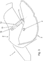
Fig. 3 eine Seitenansicht des erfindungsgemäßen Überkopf-Gepäckfaches in einer Zwischenstellung zwischen der Offenstellung gemäßFig. 2 und der Schließstellung gemäßFig. 4 ; -
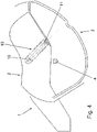
Fig. 4 eine Seitenansicht des erfindungsgemäßen Überkopf-Gepäckfaches in der Schließstellung; und -
Fig. 5 eine Detailansicht der Feder- und Dämpfungseinrichtung gemäßFig. 2 bis 4 . - In
Fig. 1 ist ein Überkopf-Gepäckfach 1 für Flugzeuge gezeigt, welches in der gezeigten Ausführung zwei ident ausgebildete Gepäckfachmodule 1a, 1b aufweist. Selbstverständlich kann jedoch auch nur ein solches Gepäckfachmodul 1a, 1b oder es können mehr als zwei solche Gepäckfachmodule 1a, 1b vorgesehen sein. Die Gepäckfachmodule 1a, 1b weisen jeweils ein feststehendes oberes Gepäckfachelement 2 auf, welches an einem Strukturelement, insbesondere an einem Flugzeugrumpf (nicht gezeigt), befestigbar ist. Darüber hinaus weist das Gepäckfach 1 ein bewegliches unteres Gepäckfachelement 3 auf. Das Gepäckfach 1 weist eine Längserstreckung auf, welche im eingebauten Zustand in Flugrichtung angeordnet ist. Das bewegliche Gepäckfachelement 3 ist beidseitig über Gelenke 4 mit Gelenkachsen an dem feststehenden Gepäckfachelement 2 aufgehängt. Die Gelenke 4 befinden sich an überlappenden Abschnitten von Seitenwänden 5 des unteren Gepäckfachelements 3 und Seitenpaneelen 6 des oberen Gepäckfachelements 2. Die Seitenwände 5 des unteren Gepäckfachelements 3 und die Seitenpaneele 6 des oberen Gepäckfachelements 2 sind jeweils im Wesentlichen eben bzw. plan ausgebildet, wobei die Seitenwände 5 des unteren Gepäckfachelements 3 im Wesentlichen parallel zu den Seitenpaneelen 6 des oberen Gepäckfachelements 2 angeordnet sind. Die Seitenwände 5 des unteren Gepäckfachelements 3 stehen seitlich von einem Boden 5a hoch, so dass das untere Gepäckfachelement 3 zur Aufnahme von Gepäckstücken als Mulde, Halbschütte bzw. U-förmiges Gepäckfach ausgebildet ist. Das untere Gepäckfachelement 2 ist zwischen einer Offenstellung (vgl. das Gepäckfachmodul 1a inFig. 1 ), in welcher eine Ladeöffnung 7 freigegeben ist, und einer Schließstellung (vgl. das Gepäckfachmodul 1b inFig. 1 ), in welcher die Ladeöffnung 7 verschlossen ist, verschwenkbar. Zu diesem Zweck weist das untere Gepäckfachelement 3 an der Sichtseite ein Griffelement 8 auf, mit welchem das Gepäckfach 1 geöffnet bzw. geschlossen werden kann. - Weiters ist aus
Fig. 1 schematisch eine Feder- und Dämpfungseinrichtung 9 zwischen dem unteren Gepäckfachelement 3 und dem oberen Gepäckfachelement 2 ersichtlich, mit welcher die Verschwenkung des beweglichen Gepäckfachelements 3 aus der geöffneten Position in die geschlossene Position unterstützt und eine Dämpfung des Schließ- bzw. Öffnungsvorgangs erzielt wird. In der gezeigten Ausführung ist je eine Feder- und Dämpfungseinrichtung 9 zwischen jeder Seitenwand 5 des unteren Gepäckfachelements 3 und jedem zugehörigen Seitenpaneel 6 des oberen Gepäckfachelements 2 vorgesehen. - In den
Fig. 2 bis 5 ist eine Ausführung des Gepäckfaches 1 gezeigt, welches wie inFig. 1 dargestellt ausgeführt sein kann, jedoch eine davon verschiedene Feder- und Dämpfungseinrichtung 9 aufweist. Nachstehend wird daher lediglich auf die Unterschiede zur Ausführung gemäßFig. 1 eingegangen. - Wie aus
Fig. 2 bis 5 ersichtlich, weist die Feder- und Dämpfungseinrichtung 9 zumindest ein Federelement 10 zur Unterstützung der Bewegung des unteren Gepäckfachelements 3 von der Offen- in die Schließstellung und ein Dämpfungselement 11 zur Dämpfung der Bewegung des unteren Gepäckfachelements 3 auf. Bevorzugt kann mittels des Dämpfungselements 11 sowohl das Öffnen als auch das Schließen des Gepäckfaches 1 gedämpft werden. - Das Dämpfungselement 11 weist in bekannter Weise einen Zylinder 11a auf, in welchem ein Kolben 11b in Längsrichtung, d.h. in axialer Richtung, verschieblich ist. In dem Zylinder 11a ist in ebenfalls bekannter Weise ein Fluid, insbesondere Öl, angeordnet. Beim Verschieben des Kolbens 11b gegenüber dem Zylinder 11a wird das Fluid durch Kanäle bzw. Ventile im Kolben 11b gedrängt. Dabei wird Dämpfarbeit verrichtet, welche in eine Erwärmung des Fluids umgesetzt wird.
- In der Ausführung der
Fig. 2 bis 5 ist das zumindest eine Federelement 10 außerhalb des Dämpfungselements 11 angeordnet, wobei sich das Federelement 10 neben dem Dämpfungselement 11 erstreckt. Die Längsachse 12 des Federelements 10 ist in eine Richtung 13 parallel zur Hauptebene des Seitenpaneels 6 des oberen Gepäckfachelements 2, d.h. quer zur Flugrichtung, versetzt zu der Längsachse 14 des Dämpfungselements 11 angeordnet. In der gezeigten Ausführung ist die Längsachse 12 des Federelements 10 im Wesentlichen parallel zur Längsachse 14 des Dämpfungselements 11 angeordnet, wobei sich die Längsachse 12 des Federelements 10 in derselben vertikalen Ebene parallel zur Hauptebene des Seitenpaneels 6 des oberen Gepäckfachelements 2 erstreckt. - Wie aus
Fig. 2 bis 5 weiters ersichtlich, weist die Feder- und Dämpfungseinrichtung 9 in der gezeigten Ausführung genau zwei Federelemente 10 auf, wobei das eine Federelement 10 auf der einen Längsseite des Dämpfungselements 11 und das andere Federelement auf der anderen Längsseite des Dämpfungselements 11 angeordnet ist. Die Federelemente 10 sind im Wesentlichen parallel zueinander angeordnet, wobei sich die Längsachsen 12 der Federelemente 10 im Wesentlichen parallel und in demselben Abstand zu dem Dämpfungselement 11 erstrecken. Beide Federelemente 10 sind in der gezeigten Ausführung als im Wesentlichen idente Schraubenfedern ausgebildet, welche in der Offenstellung des unteren Gepäckfachelementes 3 in einem gedehnten Zustand vorliegen, so dass die Bewegung des unteren Gepäckfachelementes 3 von der Offen- in die Schließstellung durch die Wirkung der Federelemente 10 unterstützt wird. - Wie aus
Fig. 2 bis 5 weiters ersichtlich, sind die einen Enden der Federelemente 10 zum Kräfte- bzw. Toleranzausgleich über ein längliches Verbindungselement 15 miteinander verbunden, welches im Wesentlichen U-förmig um eine Umlenkrolle 16 umläuft. Die anderen Enden der Federelemente 10 sind jeweils an einer gemeinsamen Lagereinrichtung 17, insbesondere einer Lagerplatte, befestigt, welche an dem Dämpfungselement 11 angebracht ist. Das eine Ende des Dämpfungselements 11 ist um eine Schwenkachse 18 verschwenkbar an der Seitenwand 5 des unteren Gepäckfachelements und das andere Ende des Dämpfungselements 11 um eine Schwenkachse 19 verschwenkbar an dem Seitenpaneel 6 des oberen Gepäckfachelements 2 angeordnet. In der gezeigten Ausführung ist die Schwenkachse 18 des Dämpfungselements 11 auf Seite des unteren Gepäckfachelements 3 an einer von der Seitenwand 5 des unteren Gepäckfachelements 3 hochstehenden Lasche angeordnet.
Claims (6)
- Überkopf-Gepäckfach (1) für ein Flugzeug, mit einem oberen Gepäckfachelement (2), mit einem unteren Gepäckfachelement (3), welches zwischen einer Offen- und einer Schließstellung beweglich ist, und mit einer ein Federelement (10) und ein Dämpfungselement (11) aufweisenden Feder- und Dämpfungseinrichtung (9), welche mit einem Seitenpaneel (6) des oberen Gepäckfachelements (2) und mit einer Seitenwand (5) des unteren Gepäckfachelements (3) verbunden ist, dadurch gekennzeichnet, dass das Federelement (10) außerhalb des Dämpfungselements (11), in eine Richtung (13) parallel zur Hauptebene des Seitenpaneels (6) des oberen Gepäckfachelements (2) bzw. der Seitenwand (5) des unteren Gepäckfachelements (3) versetzt zu dem Dämpfungselement (11) angeordnet ist, wobei die Längsachse (12) des Federelements (10) im Wesentlichen parallel zur Längsachse (14) des Dämpfungselements (11), in derselben Ebene parallel zur Hauptebene des Seitenpaneels (6) des oberen Gepäckfachelements (2) bzw. der Seitenwand (5) des unteren Gepäckfachelements (3) angeordnet ist, wobei die Federund Dämpfungseinrichtung (9) zwei Federelemente (10) aufweist, wobei das eine Federelement (10) auf der einen Seite des Dämpfungselements (11) und das andere Federelement (10) auf der anderen Seite des Dämpfungselements (11) angeordnet ist, wobei das eine Ende des Dämpfungselements (10) gelenkig an der Seitenwand (5) des unteren Gepäckfachelements (3) und das andere Ende des Dämpfungselements (11) gelenkig an dem Seitenpaneel (6) des oberen Gepäckfachelements (2) angeordnet ist, wobei die einen Enden der Federelemente (10) über eine Umlenkrolle (16) miteinander verbunden sind.
- Überkopf-Gepäckfach (1) nach Anspruch 1, dadurch gekennzeichnet, dass die Federelemente (10) benachbart des Dämpfungselements (11) angeordnet sind.
- Überkopf-Gepäckfach (1) nach Anspruch 1 oder 2, dadurch gekennzeichnet, dass die Federelemente (10) im Wesentlichen in demselben Abstand zu dem Dämpfungselement (11) angeordnet sind.
- Überkopf-Gepäckfach (1) nach einem der Ansprüche 1 bis 3, dadurch gekennzeichnet, dass die anderen Enden der Federelemente (10) an einer gemeinsamen Lagereinrichtung (17), insbesondere einer Lagerplatte, befestigt sind.
- Überkopf-Gepäckfach (1) nach einem der Ansprüche 1 bis 4, dadurch gekennzeichnet, dass als Federelement (10) eine Schraubenfeder und/oder als Dämpfungselement (11) ein Öldämpfer, vorgesehen ist.
- Überkopf-Gepäckfach (1) nach einem der Ansprüche 1 bis 5, dadurch gekennzeichnet, dass das untere Gepäckfachelement (3) über ein Gelenk (4) verschwenkbar an dem oberen Gepäckfachelement (2) angeordnet ist.
Priority Applications (1)
| Application Number | Priority Date | Filing Date | Title |
|---|---|---|---|
| HRP20221190TT HRP20221190T1 (hr) | 2016-10-21 | 2016-10-21 | Pretinac za prtljagu iznad glave u zrakoplovu |
Applications Claiming Priority (1)
| Application Number | Priority Date | Filing Date | Title |
|---|---|---|---|
| PCT/EP2016/075346 WO2018072838A1 (de) | 2016-10-21 | 2016-10-21 | Überkopf-gepäckfach für ein flugzeug |
Publications (2)
| Publication Number | Publication Date |
|---|---|
| EP3529152A1 EP3529152A1 (de) | 2019-08-28 |
| EP3529152B1 true EP3529152B1 (de) | 2022-07-20 |
Family
ID=57184457
Family Applications (1)
| Application Number | Title | Priority Date | Filing Date |
|---|---|---|---|
| EP16784899.3A Active EP3529152B1 (de) | 2016-10-21 | 2016-10-21 | Überkopf-gepäckfach für ein flugzeug |
Country Status (4)
| Country | Link |
|---|---|
| EP (1) | EP3529152B1 (de) |
| ES (1) | ES2927269T3 (de) |
| HR (1) | HRP20221190T1 (de) |
| WO (1) | WO2018072838A1 (de) |
Family Cites Families (10)
| Publication number | Priority date | Publication date | Assignee | Title |
|---|---|---|---|---|
| DE4335151C2 (de) * | 1993-10-15 | 1996-09-26 | Daimler Benz Aerospace Airbus | Überkopf-Gepäckablage, insbesondere für ein Passagierflugzeug |
| AT413812B (de) * | 2001-10-17 | 2006-06-15 | Fischer Adv Components Gmbh | Aufhängevorrichtung für absenkbare gebäckablagebehälter |
| DE202009006931U1 (de) * | 2009-05-13 | 2011-04-28 | Krischke-Lengersdorf, Christian | Druckfluidlineardämpfer mit Federmechanismus |
| US8943751B2 (en) * | 2010-04-20 | 2015-02-03 | Be Intellectual Property, Inc. | Lift assist mechanism |
| DE102011110750B4 (de) * | 2011-08-16 | 2021-08-05 | Diehl Aviation Laupheim Gmbh | Gepäckablagefach für ein Flugzeug |
| AT513939A1 (de) | 2013-02-01 | 2014-08-15 | Facc Ag | Überkopf-Gepäckfach für Flugzeuge und Flugzeug mit solchen Überkopf-Gepäckfächern |
| DE102014103463B4 (de) * | 2014-03-13 | 2021-08-12 | General Dynamics European Land Systems - Mowag Gmbh | Verfahren und Verwendung einer Beladungseinheit zum Dämpfen von im Überlastfall einwirkenden Belastungen zum Schutz vor Schäden |
| AT515849A1 (de) * | 2014-05-26 | 2015-12-15 | Facc Ag | Überkopf-Gepäckfach |
| DE102014012125A1 (de) * | 2014-08-14 | 2016-02-18 | Airbus Operations Gmbh | Kabelführungsanordnung für ein Gepäckfach |
| ES2758024T3 (es) * | 2015-11-03 | 2020-05-04 | Facc Ag | Compartimiento superior de equipaje para un avión |
-
2016
- 2016-10-21 ES ES16784899T patent/ES2927269T3/es active Active
- 2016-10-21 EP EP16784899.3A patent/EP3529152B1/de active Active
- 2016-10-21 HR HRP20221190TT patent/HRP20221190T1/hr unknown
- 2016-10-21 WO PCT/EP2016/075346 patent/WO2018072838A1/de not_active Ceased
Also Published As
| Publication number | Publication date |
|---|---|
| HRP20221190T1 (hr) | 2022-12-09 |
| EP3529152A1 (de) | 2019-08-28 |
| WO2018072838A1 (de) | 2018-04-26 |
| ES2927269T3 (es) | 2022-11-03 |
Similar Documents
| Publication | Publication Date | Title |
|---|---|---|
| DE4240416B4 (de) | Versteifungsanordnung für einen Kraftfahrzeug-Aufbau mit einem Türträger | |
| WO2018104199A1 (de) | Mehrgelenkscharnier | |
| EP1436194A1 (de) | Aufhängevorrichtung für absenkbare gepäckablagebehälter | |
| EP3997293B1 (de) | Anordnung zur führung einer schiebetür oder falt-schiebetür an einer möbelwand | |
| AT517286B1 (de) | Überkopf-Gepäckfach für ein Flugzeug | |
| DE102015120565B4 (de) | Möbel oder Haushaltsgerät und Mehrgelenkscharnier | |
| EP0894933B1 (de) | Behälter mit einer Tür | |
| EP3279416A1 (de) | Dämpfereinrichtung | |
| DE102008032750B4 (de) | Parallelausstellfenster | |
| DE102018008201A1 (de) | Einzugsvorrichtung für zwei Endlagen | |
| DE102015102388A1 (de) | Schiebe-Schwenkmechanik einer Ablage eines Möbels und Möbel | |
| DE102015102393A1 (de) | Schwenkbeschlag | |
| EP2943425B1 (de) | Rammpuffer | |
| DE202008015265U1 (de) | Fenster | |
| AT523303B1 (de) | Führungsvorrichtung zur Führung eines Möbelteils | |
| DE102010026190A1 (de) | Türüberlastschutzvorrichtung | |
| EP3922798B1 (de) | Tür mit einem scharnier mit integrierter anschlagdämpfung | |
| AT410536B (de) | Aufhängevorrichtung für absenkbare gepäckablagebehälter | |
| EP3880924B1 (de) | Möbel mit einer anordnung zur führung wenigstens einer falt-schiebe-tür | |
| DE102016120313B4 (de) | Energieführungskette mit Verstärkungselement | |
| DE202011102484U1 (de) | Schließmechanismus für eine mit Kraftunterstützung schließende Schiebetüre | |
| DE202008001812U1 (de) | Verdeckt angeordnetes 180-Grad-Scharnier | |
| DE102015102387A1 (de) | Schiebe-Schwenkmechanik einer Ablage eines Haushaltsgerätes und Haushaltsgerät | |
| EP3529152A1 (de) | Überkopf-gepäckfach für ein flugzeug | |
| EP3246500B1 (de) | Schiebetürsystem mit dämpferanordnung |
Legal Events
| Date | Code | Title | Description |
|---|---|---|---|
| REG | Reference to a national code |
Ref country code: HR Ref legal event code: TUEP Ref document number: P20221190T Country of ref document: HR |
|
| STAA | Information on the status of an ep patent application or granted ep patent |
Free format text: STATUS: UNKNOWN |
|
| STAA | Information on the status of an ep patent application or granted ep patent |
Free format text: STATUS: THE INTERNATIONAL PUBLICATION HAS BEEN MADE |
|
| PUAI | Public reference made under article 153(3) epc to a published international application that has entered the european phase |
Free format text: ORIGINAL CODE: 0009012 |
|
| STAA | Information on the status of an ep patent application or granted ep patent |
Free format text: STATUS: REQUEST FOR EXAMINATION WAS MADE |
|
| 17P | Request for examination filed |
Effective date: 20190521 |
|
| AK | Designated contracting states |
Kind code of ref document: A1 Designated state(s): AL AT BE BG CH CY CZ DE DK EE ES FI FR GB GR HR HU IE IS IT LI LT LU LV MC MK MT NL NO PL PT RO RS SE SI SK SM TR |
|
| AX | Request for extension of the european patent |
Extension state: BA ME |
|
| DAV | Request for validation of the european patent (deleted) | ||
| DAX | Request for extension of the european patent (deleted) | ||
| STAA | Information on the status of an ep patent application or granted ep patent |
Free format text: STATUS: EXAMINATION IS IN PROGRESS |
|
| 17Q | First examination report despatched |
Effective date: 20200921 |
|
| GRAP | Despatch of communication of intention to grant a patent |
Free format text: ORIGINAL CODE: EPIDOSNIGR1 |
|
| STAA | Information on the status of an ep patent application or granted ep patent |
Free format text: STATUS: GRANT OF PATENT IS INTENDED |
|
| INTG | Intention to grant announced |
Effective date: 20220314 |
|
| GRAS | Grant fee paid |
Free format text: ORIGINAL CODE: EPIDOSNIGR3 |
|
| GRAA | (expected) grant |
Free format text: ORIGINAL CODE: 0009210 |
|
| STAA | Information on the status of an ep patent application or granted ep patent |
Free format text: STATUS: THE PATENT HAS BEEN GRANTED |
|
| AK | Designated contracting states |
Kind code of ref document: B1 Designated state(s): AL AT BE BG CH CY CZ DE DK EE ES FI FR GB GR HR HU IE IS IT LI LT LU LV MC MK MT NL NO PL PT RO RS SE SI SK SM TR |
|
| REG | Reference to a national code |
Ref country code: CH Ref legal event code: EP |
|
| REG | Reference to a national code |
Ref country code: DE Ref legal event code: R096 Ref document number: 502016015093 Country of ref document: DE |
|
| REG | Reference to a national code |
Ref country code: AT Ref legal event code: REF Ref document number: 1505401 Country of ref document: AT Kind code of ref document: T Effective date: 20220815 |
|
| REG | Reference to a national code |
Ref country code: IE Ref legal event code: FG4D Free format text: LANGUAGE OF EP DOCUMENT: GERMAN |
|
| REG | Reference to a national code |
Ref country code: ES Ref legal event code: FG2A Ref document number: 2927269 Country of ref document: ES Kind code of ref document: T3 Effective date: 20221103 |
|
| REG | Reference to a national code |
Ref country code: LT Ref legal event code: MG9D |
|
| REG | Reference to a national code |
Ref country code: NL Ref legal event code: MP Effective date: 20220720 |
|
| REG | Reference to a national code |
Ref country code: HR Ref legal event code: ODRP Ref document number: P20221190T Country of ref document: HR Payment date: 20221011 Year of fee payment: 7 |
|
| REG | Reference to a national code |
Ref country code: HR Ref legal event code: T1PR Ref document number: P20221190 Country of ref document: HR |
|
| PG25 | Lapsed in a contracting state [announced via postgrant information from national office to epo] |
Ref country code: SE Free format text: LAPSE BECAUSE OF FAILURE TO SUBMIT A TRANSLATION OF THE DESCRIPTION OR TO PAY THE FEE WITHIN THE PRESCRIBED TIME-LIMIT Effective date: 20220720 Ref country code: RS Free format text: LAPSE BECAUSE OF FAILURE TO SUBMIT A TRANSLATION OF THE DESCRIPTION OR TO PAY THE FEE WITHIN THE PRESCRIBED TIME-LIMIT Effective date: 20220720 Ref country code: PT Free format text: LAPSE BECAUSE OF FAILURE TO SUBMIT A TRANSLATION OF THE DESCRIPTION OR TO PAY THE FEE WITHIN THE PRESCRIBED TIME-LIMIT Effective date: 20221121 Ref country code: NO Free format text: LAPSE BECAUSE OF FAILURE TO SUBMIT A TRANSLATION OF THE DESCRIPTION OR TO PAY THE FEE WITHIN THE PRESCRIBED TIME-LIMIT Effective date: 20221020 Ref country code: NL Free format text: LAPSE BECAUSE OF FAILURE TO SUBMIT A TRANSLATION OF THE DESCRIPTION OR TO PAY THE FEE WITHIN THE PRESCRIBED TIME-LIMIT Effective date: 20220720 Ref country code: LV Free format text: LAPSE BECAUSE OF FAILURE TO SUBMIT A TRANSLATION OF THE DESCRIPTION OR TO PAY THE FEE WITHIN THE PRESCRIBED TIME-LIMIT Effective date: 20220720 Ref country code: LT Free format text: LAPSE BECAUSE OF FAILURE TO SUBMIT A TRANSLATION OF THE DESCRIPTION OR TO PAY THE FEE WITHIN THE PRESCRIBED TIME-LIMIT Effective date: 20220720 Ref country code: FI Free format text: LAPSE BECAUSE OF FAILURE TO SUBMIT A TRANSLATION OF THE DESCRIPTION OR TO PAY THE FEE WITHIN THE PRESCRIBED TIME-LIMIT Effective date: 20220720 |
|
| PG25 | Lapsed in a contracting state [announced via postgrant information from national office to epo] |
Ref country code: PL Free format text: LAPSE BECAUSE OF FAILURE TO SUBMIT A TRANSLATION OF THE DESCRIPTION OR TO PAY THE FEE WITHIN THE PRESCRIBED TIME-LIMIT Effective date: 20220720 Ref country code: IS Free format text: LAPSE BECAUSE OF FAILURE TO SUBMIT A TRANSLATION OF THE DESCRIPTION OR TO PAY THE FEE WITHIN THE PRESCRIBED TIME-LIMIT Effective date: 20221120 Ref country code: GR Free format text: LAPSE BECAUSE OF FAILURE TO SUBMIT A TRANSLATION OF THE DESCRIPTION OR TO PAY THE FEE WITHIN THE PRESCRIBED TIME-LIMIT Effective date: 20221021 |
|
| REG | Reference to a national code |
Ref country code: DE Ref legal event code: R097 Ref document number: 502016015093 Country of ref document: DE |
|
| PG25 | Lapsed in a contracting state [announced via postgrant information from national office to epo] |
Ref country code: SM Free format text: LAPSE BECAUSE OF FAILURE TO SUBMIT A TRANSLATION OF THE DESCRIPTION OR TO PAY THE FEE WITHIN THE PRESCRIBED TIME-LIMIT Effective date: 20220720 Ref country code: RO Free format text: LAPSE BECAUSE OF FAILURE TO SUBMIT A TRANSLATION OF THE DESCRIPTION OR TO PAY THE FEE WITHIN THE PRESCRIBED TIME-LIMIT Effective date: 20220720 Ref country code: DK Free format text: LAPSE BECAUSE OF FAILURE TO SUBMIT A TRANSLATION OF THE DESCRIPTION OR TO PAY THE FEE WITHIN THE PRESCRIBED TIME-LIMIT Effective date: 20220720 Ref country code: CZ Free format text: LAPSE BECAUSE OF FAILURE TO SUBMIT A TRANSLATION OF THE DESCRIPTION OR TO PAY THE FEE WITHIN THE PRESCRIBED TIME-LIMIT Effective date: 20220720 |
|
| PLBE | No opposition filed within time limit |
Free format text: ORIGINAL CODE: 0009261 |
|
| STAA | Information on the status of an ep patent application or granted ep patent |
Free format text: STATUS: NO OPPOSITION FILED WITHIN TIME LIMIT |
|
| PG25 | Lapsed in a contracting state [announced via postgrant information from national office to epo] |
Ref country code: SK Free format text: LAPSE BECAUSE OF FAILURE TO SUBMIT A TRANSLATION OF THE DESCRIPTION OR TO PAY THE FEE WITHIN THE PRESCRIBED TIME-LIMIT Effective date: 20220720 Ref country code: MC Free format text: LAPSE BECAUSE OF FAILURE TO SUBMIT A TRANSLATION OF THE DESCRIPTION OR TO PAY THE FEE WITHIN THE PRESCRIBED TIME-LIMIT Effective date: 20220720 Ref country code: EE Free format text: LAPSE BECAUSE OF FAILURE TO SUBMIT A TRANSLATION OF THE DESCRIPTION OR TO PAY THE FEE WITHIN THE PRESCRIBED TIME-LIMIT Effective date: 20220720 |
|
| REG | Reference to a national code |
Ref country code: CH Ref legal event code: PL |
|
| REG | Reference to a national code |
Ref country code: BE Ref legal event code: MM Effective date: 20221031 |
|
| 26N | No opposition filed |
Effective date: 20230421 |
|
| P01 | Opt-out of the competence of the unified patent court (upc) registered |
Effective date: 20230522 |
|
| PG25 | Lapsed in a contracting state [announced via postgrant information from national office to epo] |
Ref country code: LU Free format text: LAPSE BECAUSE OF NON-PAYMENT OF DUE FEES Effective date: 20221021 Ref country code: AL Free format text: LAPSE BECAUSE OF FAILURE TO SUBMIT A TRANSLATION OF THE DESCRIPTION OR TO PAY THE FEE WITHIN THE PRESCRIBED TIME-LIMIT Effective date: 20220720 |
|
| PG25 | Lapsed in a contracting state [announced via postgrant information from national office to epo] |
Ref country code: LI Free format text: LAPSE BECAUSE OF NON-PAYMENT OF DUE FEES Effective date: 20221031 Ref country code: CH Free format text: LAPSE BECAUSE OF NON-PAYMENT OF DUE FEES Effective date: 20221031 |
|
| PG25 | Lapsed in a contracting state [announced via postgrant information from national office to epo] |
Ref country code: SI Free format text: LAPSE BECAUSE OF FAILURE TO SUBMIT A TRANSLATION OF THE DESCRIPTION OR TO PAY THE FEE WITHIN THE PRESCRIBED TIME-LIMIT Effective date: 20220720 |
|
| PG25 | Lapsed in a contracting state [announced via postgrant information from national office to epo] |
Ref country code: BE Free format text: LAPSE BECAUSE OF NON-PAYMENT OF DUE FEES Effective date: 20221031 |
|
| REG | Reference to a national code |
Ref country code: HR Ref legal event code: ODRP Ref document number: P20221190 Country of ref document: HR Payment date: 20231010 Year of fee payment: 8 |
|
| PG25 | Lapsed in a contracting state [announced via postgrant information from national office to epo] |
Ref country code: IE Free format text: LAPSE BECAUSE OF NON-PAYMENT OF DUE FEES Effective date: 20221021 |
|
| PG25 | Lapsed in a contracting state [announced via postgrant information from national office to epo] |
Ref country code: HU Free format text: LAPSE BECAUSE OF FAILURE TO SUBMIT A TRANSLATION OF THE DESCRIPTION OR TO PAY THE FEE WITHIN THE PRESCRIBED TIME-LIMIT; INVALID AB INITIO Effective date: 20161021 |
|
| PG25 | Lapsed in a contracting state [announced via postgrant information from national office to epo] |
Ref country code: CY Free format text: LAPSE BECAUSE OF FAILURE TO SUBMIT A TRANSLATION OF THE DESCRIPTION OR TO PAY THE FEE WITHIN THE PRESCRIBED TIME-LIMIT Effective date: 20220720 |
|
| PG25 | Lapsed in a contracting state [announced via postgrant information from national office to epo] |
Ref country code: MK Free format text: LAPSE BECAUSE OF FAILURE TO SUBMIT A TRANSLATION OF THE DESCRIPTION OR TO PAY THE FEE WITHIN THE PRESCRIBED TIME-LIMIT Effective date: 20220720 |
|
| PG25 | Lapsed in a contracting state [announced via postgrant information from national office to epo] |
Ref country code: TR Free format text: LAPSE BECAUSE OF FAILURE TO SUBMIT A TRANSLATION OF THE DESCRIPTION OR TO PAY THE FEE WITHIN THE PRESCRIBED TIME-LIMIT Effective date: 20220720 |
|
| PG25 | Lapsed in a contracting state [announced via postgrant information from national office to epo] |
Ref country code: BG Free format text: LAPSE BECAUSE OF FAILURE TO SUBMIT A TRANSLATION OF THE DESCRIPTION OR TO PAY THE FEE WITHIN THE PRESCRIBED TIME-LIMIT Effective date: 20220720 |
|
| PG25 | Lapsed in a contracting state [announced via postgrant information from national office to epo] |
Ref country code: MT Free format text: LAPSE BECAUSE OF FAILURE TO SUBMIT A TRANSLATION OF THE DESCRIPTION OR TO PAY THE FEE WITHIN THE PRESCRIBED TIME-LIMIT Effective date: 20220720 |
|
| REG | Reference to a national code |
Ref country code: HR Ref legal event code: ODRP Ref document number: P20221190 Country of ref document: HR Payment date: 20241010 Year of fee payment: 9 |
|
| REG | Reference to a national code |
Ref country code: HR Ref legal event code: ODRP Ref document number: P20221190 Country of ref document: HR Payment date: 20251009 Year of fee payment: 10 |
|
| PGFP | Annual fee paid to national office [announced via postgrant information from national office to epo] |
Ref country code: DE Payment date: 20251020 Year of fee payment: 10 |
|
| PGFP | Annual fee paid to national office [announced via postgrant information from national office to epo] |
Ref country code: GB Payment date: 20251024 Year of fee payment: 10 |
|
| PGFP | Annual fee paid to national office [announced via postgrant information from national office to epo] |
Ref country code: AT Payment date: 20251009 Year of fee payment: 10 |
|
| PGFP | Annual fee paid to national office [announced via postgrant information from national office to epo] |
Ref country code: IT Payment date: 20251031 Year of fee payment: 10 |
|
| PGFP | Annual fee paid to national office [announced via postgrant information from national office to epo] |
Ref country code: HR Payment date: 20251009 Year of fee payment: 10 Ref country code: FR Payment date: 20251027 Year of fee payment: 10 |
|
| PGFP | Annual fee paid to national office [announced via postgrant information from national office to epo] |
Ref country code: ES Payment date: 20251114 Year of fee payment: 10 |